HARRIS TR-0075-E Mobile XG-25M, 136-174MHz, 50W User Manual 1
HARRIS CORPORATION Mobile XG-25M, 136-174MHz, 50W 1
HARRIS >
Contents
- 1. User Manual 1
- 2. User Manual 2
User Manual 1

Operator’s Manual
14221-1510-2000
May/12
XG-25M Mobile Radio
14221-1510-2000
2
MANUAL REVISION HISTORY
REV. DATE REASON FOR CHANGE
– May/12 Initial release.
Harris Corporation, Public Safety and Professional Communications (PSPC) Business, continually evaluates its technical
publications for completeness, technical accuracy, and organization. You can assist in this process by submitting your
comments and suggestions to the following:
Harris Corporation fax your comments to: 1-434-455-6851
PSPC Business or
Technical Publications e-mail us at: PSPC_TechPubs@harris.com
221 Jefferson Ridge Parkway
Lynchburg, VA 24501 ACKNOWLEDGEMENT
This device is made under license under one or more of the following US patents: 4,590,473; 4,636,791; 5,148,482;
5,185,796; 5,271,017; 5,377,229; 4,716,407; 4,972,460; 5,502,767; 5,146,497; 5,164,986; 5,185,795; 5,226,084; 5,247,579;
5,491,772; 5,517,511; 5,630,011; 5,649,050; 5,701,390; 5,715,365; 5,754,974; 5,826,222; 5,870,405; 6,161,089; and
6,199,037 B1. DVSI claims certain rights, including patent rights under aforementioned U.S. patents, and under other U.S.
and foreign patents and patents pending. Any use of this software or technology requires a separate written license from
DVSI. CREDITS
Harris, assuredcommunications are registered trademarks of Harris Corporation.
AMBE is a registered trademark and IMBE, AMBE+, and AMBE+2 are trademarks of Digital Voice Systems, Inc.
All other brand and product names are trademarks, registered trademarks, or service marks of their respective holders.
NOTICE!
The material contained herein is subject to U.S. export approval. No export or re-export is permitted without written
approval from the U.S. Government. Rated: EAR99 in accordance with U.S. Dept. of Commerce regulations 15CFR774,
Export Administration Regulations.
Information and descriptions contained herein are the property of Harris Corporation. Such information and descriptions may
not be copied or reproduced by any means, or disseminated or distributed without the express prior written permission of
Harris Corporation, PSPC Business, 221 Jefferson Ridge Parkway, Lynchburg, VA 24501.
The voice coding technology embodied in this product is protected by intellectual property rights including patent rights,
copyrights, and trade secrets of Digital Voice Systems, Inc. The user of this technology is explicitly prohibited from
attempting to decompile, reverse engineer, or disassemble the Object Code, or in any other way convert the Object Code into
human-readable form.
Repairs to this equipment should be made only by an authorized service technician or facility designated by the supplier. Any
repairs, alterations or substitutions of recommended parts made by the user to this equipment not approved by the
manufacturer could void the user's authority to operate the equipment in addition to the manufacturer's warranty.
This product conforms to the European Union WEEE Directive 2002/96/EC. Do not dispose of this product in a
public landfill. Take it to a recycling center at the end of its life.
This manual is published by Harris Corporation without any warranty. Improvements and changes to this manual necessitated by typographical errors,
inaccuracies of current information, or improvements to programs and/or equipment, may be made by Harris Corporation
at any time and without notice.
Such changes will be incorporated into new editions of this manual. No part of this manual may be reproduced or transmitted i
n any form or by any means,
electronic or mechanical, including photocopying and recording, for any purpose, without the express written permission of Harris Corporation.
Copyright© 2012, Harris Corporation

14221-1510-2000
3
TABLE OF CONTENTS
Section Page
1 SAFETY SYMBOL CONVENTIONS ......................................................................................... 6
2 RF ENERGY EXPOSURE INFORMATION ............................................................................. 6
2.1 RF ENERGY EXPOSURE AWARENESS AND CONTROL INFORMATION FOR FCC
OCCUPATIONAL USE REQUIREMENTS ........................................................................................ 6
2.1.1 Federal Communications Commission Regulations ............................................................... 7
2.2 COMPLIANCE WITH RF EXPOSURE STANDARDS ...................................................................... 7
2.2.1 Mobile Antennas .................................................................................................................... 8
2.2.2 Approved Accessories ............................................................................................................ 8
2.2.3 Contact Information ................................................................................................................ 8
3 OPERATION SAFETY RECOMMENDATIONS ..................................................................... 8
3.1 OCCUPATIONAL SAFETY GUIDELINES AND SAFETY TRAINING INFORMATION ............. 8
3.2 TRANSMITTER HAZARDS ............................................................................................................... 9
3.3 SAFE DRIVING RECOMMENDATIONS ........................................................................................ 10
3.4 OPERATING RULES AND REGULATIONS .................................................................................. 10
3.5 OPERATING TIPS ............................................................................................................................. 11
3.6 RADIO FREQUENCY INTERFERENCE ......................................................................................... 11
3.6.1 FCC Part 15 .......................................................................................................................... 11
3.6.2 Industry Canada .................................................................................................................... 11
4 MARITIME FREQUENCIES .................................................................................................... 12
5 INTRODUCTION ........................................................................................................................ 18
5.1 GENERAL DESCRIPTION ............................................................................................................... 18
5.2 RELATED PUBLICATIONS ............................................................................................................. 19
5.3 REPLACEMENT PARTS .................................................................................................................. 19
6 CONTROLS AND INDICATORS ............................................................................................. 20
6.1 POWER ON/OFF/VOLUME CONTROL .......................................................................................... 20
6.2 GROUP/CHANNEL CONTROL ....................................................................................................... 20
6.3 BUTTONS .......................................................................................................................................... 20
6.4 DISPLAY ........................................................................................................................................... 21
6.4.1 General Information ............................................................................................................. 21
6.4.2 Status Icons ........................................................................................................................... 21
6.4.3 Status Messages .................................................................................................................... 22
6.5 TRANSMIT/RECEIVE INDICATOR ............................................................................................... 22
6.6 ALERT TONES .................................................................................................................................. 22
7 COMMON OPERATIONS ......................................................................................................... 24
7.1 TURNING THE RADIO ON AND OFF AND ADJUSTING VOLUME ........................................... 24
7.2 CONNECTING A MICROPHONE (“MIC”) ..................................................................................... 24
7.3 LOCKING AND UNLOCKING FRONT PANEL BUTTONS .......................................................... 24
7.4 DISPLAY AND BUTTON BACKLIGHT ADJUSTMENT ............................................................... 24
7.5 DISPLAY CONTRAST ADJUSTMENT ........................................................................................... 25
7.6 SYSTEM SELECTION ...................................................................................................................... 25
7.6.1 +/– Buttons Select System .................................................................................................... 25
7.6.2 Group/Channel Control Selects System ............................................................................... 25
7.7 GROUP/CHANNEL SELECTION .................................................................................................... 25
7.7.1 Group/Channel Control Selects Groups/Channels................................................................ 25
7.7.2 +/– Buttons Select Groups/Channels .................................................................................... 25
7.8
TRANSMIT
POWER
LEVEL
ADJUSTMENT ................................................................................. 25

14221-1510-2000
4
TABLE OF CONTENTS
Section Page
7.8.1 Tx Power Adjustment via the Menu ..................................................................................... 26
7.8.2 Tx Power Adjustment via a Pre-Programmed Button ........................................................... 26
7.9 MENU OPERATIONS ....................................................................................................................... 26
7.10 MACRO KEYS ................................................................................................................................... 27
8 P25 CONVENTIONAL OPERATIONS .................................................................................... 28
8.1 GROUP CALLS IN P25 CONVENTIONAL MODE ......................................................................... 28
8.1.1 Receiving a Group Call ......................................................................................................... 28
8.1.2 Transmitting a Group Call .................................................................................................... 28
8.2 INDIVIDUAL CALLS IN P25 CONVENTIONAL MODE ............................................................... 28
8.2.1 Receiving and Responding to an Individual Call .................................................................. 28
8.2.2 Transmitting an Individual Call ............................................................................................ 29
8.3 STATUS OPERATIONS .................................................................................................................... 29
9 ANALOG CONVENTIONAL OPERATIONS ......................................................................... 31
9.1 RECEIVING A CALL IN ANALOG CONVENTIONAL MODE ..................................................... 31
9.2 TRANSMITTING A CALL IN ANALOG CONVENTIONAL MODE ............................................. 31
9.3 SCANNING CHANNELS IN ANALOG CONVENTION MODE .................................................... 32
9.3.1 Turning Scan On and Off ...................................................................................................... 32
9.3.2 Adding Channels to the Scan List ......................................................................................... 32
9.3.3 Deleting Channels from the Scan List .................................................................................. 33
9.4 SQUELCH ADJUSTMENT IN ANALOG CONVENTIONAL MODE ............................................ 33
9.5 TYPE 99 DECODE IN ANALOG CONVENTIONAL MODE .......................................................... 34
9.5.1 General Information .............................................................................................................. 34
9.5.2 Type 99 Enable/Disable via Menu Selection ........................................................................ 35
9.5.3 Type 99 Enable/Disable via a Pre-Programmed Button ....................................................... 35
9.5.4 Type 99 With or Without Channel Guard ............................................................................. 35
9.5.5 Resetting Type 99 After a Decoded Call .............................................................................. 35
9.5.6 Type 99 Disable After Radio PTT ........................................................................................ 35
9.6 EMERGENCY CALLS IN ANALOG CONVENTIONAL MODE ................................................... 36
9.6.1 G-STAR Emergency Signalling ........................................................................................... 36
9.6.2 5-Tone Emergency Signalling .............................................................................................. 36
9.6.3 Tone Encode Transmission ................................................................................................... 36
10 CUSTOMER SERVICE .............................................................................................................. 37
10.1 CUSTOMER CARE ........................................................................................................................... 37
10.2 TECHNICAL ASSISTANCE ............................................................................................................. 37
11 WARRANTY REGISTRATION ................................................................................................ 37
12 WARRANTY ................................................................................................................................ 38
(Continued)

14221-1510-2000
5
LIST OF TABLES
Page
Table 2-1: Recommended Minimum Safe Lateral Distance from Transmitting Antenna ..................................... 8
Table 4-1: Maritime Frequencies ........................................................................................................................ 12
Table 6-1: Button Functions ................................................................................................................................ 20
Table 6-2: Status Icons ........................................................................................................................................ 21
Table 6-3: Status Messages ................................................................................................................................. 22
Table 6-4: Alert Tones (“Beeps”) ........................................................................................................................ 23
Table 7-1: Menu Items (Programmable) ............................................................................................................. 27
LIST OF FIGURES
Page
Figure 5-1: XG-25M Mobile Radio (Front View) .............................................................................................. 18
Figure 6-1: XG-25M Display (Generalized) ....................................................................................................... 21
14221-1510-2000
6
1 SAFETY SYMBOL CONVENTIONS
The following conventions are used in this manual to alert the user to general safety precautions that must
be observed during all phases of operation, installation, service, and repair of this product. Failure to
comply with these precautions or with specific warnings elsewhere violates safety standards of design,
manufacture, and intended use of the product. Harris Corporation assumes no liability for the customer’s
failure to comply with these standards.
WARNING
The WARNING symbol calls attention to a procedure, practice, or the like, which,
if not correctly performed or adhered to, could result in personal injury. Do not
proceed beyond a WARNING symbol until the conditions identified are fully
understood or met.
CAUTION
The CAUTION symbol calls attention to an operating procedure, practice, or the like,
which, if not performed correctly or adhered to, could result in damage to the
equipment or severely degrade equipment performance.
NOTE
The NOTE symbol calls attention to supplemental information, which may improve
system performance or clarify a process or procedure.
2 RF ENERGY EXPOSURE INFORMATION
2.1 RF ENERGY EXPOSURE AWARENESS AND CONTROL
INFORMATION FOR FCC OCCUPATIONAL USE REQUIREMENTS
Before using the two-way mobile radio, review the following important RF energy awareness and
control information and operational instructions. Comply with this information and instructions in
order to ensure compliance with RF exposure guidelines.
This radio is intended for use in occupational/controlled conditions, where users
have full knowledge of their exposure and can exercise control over their
exposure to remain below RF exposure limits. This radio is NOT authorized for
general population, consumer, or any other use.
Changes or modifications not expressly approved by Harris
could void the user's
authority to operate the equipment.
This two-way radio uses electromagnetic energy in the radio frequency (RF) spectrum to provide
communications between two or more users over a distance. It uses RF energy or radio waves to send and
receive calls. RF energy is one form of electromagnetic energy. Other forms include, but are not limited
to, electric power, sunlight, and x-rays. RF energy, however, should not be confused with these other
forms of electromagnetic energy, which, when used improperly, can cause biological damage. Very high
levels of x-rays, for example, can damage tissues and genetic material.
Experts in science, engineering, medicine, health, and industry work with organizations to develop
standards for exposure to RF energy. These standards provide recommended levels of RF exposure for
both workers and the general public. These recommended RF exposure levels include substantial margins
WARNING
CAUTION

14221-1510-2000
7
of protection. All two-way radios marketed in North America are designed, manufactured, and tested to
ensure they meet government-established RF exposure levels. In addition, manufacturers also recommend
specific operating instructions to users of two-way radios. These instructions are important because they
inform users about RF energy exposure and provide simple procedures on how to control it. Refer to the
following websites for more information on what RF energy exposure is and how to control exposure to
assure compliance with established RF exposure limits:
http://www.fcc.gov/oet/rfsafety/rf-faqs.html
http://www.osha.gov./SLTC/radiofrequencyradiation/index.html
2.1.1 Federal Communications Commission Regulations
Before it was marketed in the United States, the XG-25M two-way mobile radio was tested to ensure
compliance with FCC RF energy exposure limits for two-way mobile radios. When two-way radios are
used as a consequence of employment, the FCC requires users to be fully aware of and able to control
their exposure to meet occupational requirements. Exposure awareness can be facilitated by the use of a
label directing users to specific user awareness information. The radio has an RF exposure product label.
Also, the Installation and Product Safety Manual and this Operator’s Manual include information and
operating instructions required to control RF exposure and to satisfy compliance requirements.
2.2 COMPLIANCE WITH RF EXPOSURE STANDARDS
The XG-25M two-way mobile radio is designed and tested to comply with a number of national and
international standards and guidelines regarding human exposure to RF electromagnetic energy. This
radio complies with the IEEE and ICNIRP exposure limits for occupational/controlled RF exposure
environment at duty-cycle times of up to 50% (50% transmit, 50% receive), and it is authorized by the
FCC for occupational use. In terms of measuring RF energy for compliance with the FCC exposure
guidelines, the radio’s antenna radiates measurable RF energy only while it is transmitting (talking), not
when it is receiving (listening), or in a standby mode.
The XG-25M two-way mobile radio complies with the following RF energy exposure standards and
guidelines:
• United States Federal Communications Commission (FCC), Code of Federal Regulations; 47 CFR
§ 2 sub-part J.
• American National Standards Institute (ANSI)/Institute of Electrical and Electronic Engineers (IEEE)
C95.1-2005.
• Institute of Electrical and Electronic Engineers (IEEE) C95.1-2005.
• IC Standard RSS-102, Issue 2, 2005: Spectrum Management and Telecommunications Radio
Standards Specification. Radiofrequency Exposure Compliance of Radiocommunication Apparatus
(All Frequency Bands).
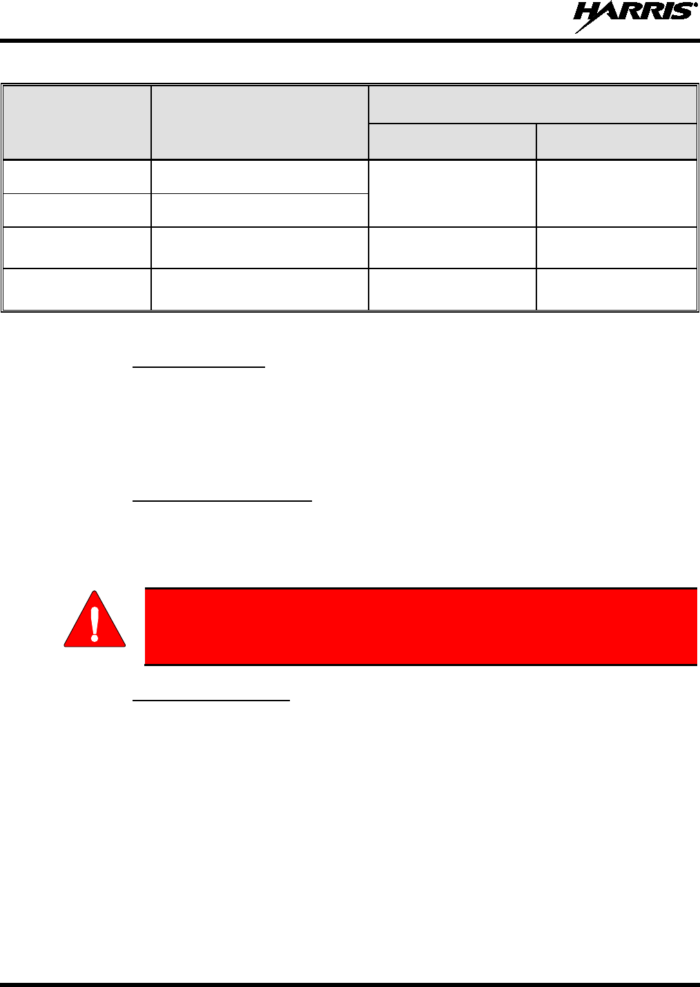
Table 2-1 lists the recommended minimum safe lateral distances
for a controlled
environment and for unaware bystanders in an uncontrolled environment, from
transmitting antennas (i.e., monopoles over a ground plane, or dipoles) at rated radio
power for mobile radios installed in a vehicle. Transmit only when unaware bystanders
are at least the uncontrolled recommended minimum safe lateral distance away from
the transmitting antenna.
Based on the highest radiated RF power and the highest antenna gain in antennas to be used with
XG-25M, the distances listed in Table 2-1 are considered as safe distances for controlled and uncontrolled
environments with the XG-25M mobile radio transmitting at a maximum 50% duty cycle:
CAUTION
14221-1510-2000
8
Table 2-1: Recommended Minimum Safe Lateral Distance from Transmitting Antenna
ANTENNA
ELEMENT PART
NUMBER ANTENNA DESCRIPTION
RECOMMENDED MINIMUM LATERAL HUMAN BODY
DISTANCE FROM TRANSMITTING ANTENNA
CONTROLLED
ENVIRONMENT UNCONTROLLED
ENVIRONMENT
AN-225002-001 136 to 174 MHz, 0 dBd Gain 24.8 Inches
(63 Centimeters) 55.1 Inches
(140 Centimeters)
AN-225006-001 132 to 960 MHz, 0 dBd Gain*
AN-225002-003 136 to 174 MHz, 3 dBd Gain* 35.0 Inches
(89 Centimeters) 78.0 Inches
(198 Centimeters)
AN-225002-004 136 to 174 MHz, 2.4 dBd Gain* 32.7 Inches
(83 Centimeters) 72.8 Inches
(185 Centimeters)
* Element must be trimmed to proper length in order to minimize antenna system VSWR.
2.2.1 Mobile Antennas
The antenna(s) for the radio must be installed in accordance with procedures presented in the Installation
and Product Safety Manual. Installation is limited to a metal-body motor vehicle or vehicles with
appropriate ground planes.
Use only approved/supplied antenna(s) or an approved replacement antenna. Unauthorized antennas,
modifications, or attachments can cause the FCC RF exposure limits to be exceeded.
2.2.2 Approved Accessories
The radio has been tested and meets FCC RF guidelines when used with accessories supplied or
designated for use with it. Use of other accessories may not ensure compliance with the FCC’s RF
exposure guidelines, and may violate FCC regulations. For a list of approved accessories refer to the
Installation and Product Safety Manual and/or the Harris Products and Services Catalog.
Always use Harris authorized accessories (antennas, speaker/mics, etc). Use of
unauthorized accessories may cause the FCC Occupational/Controlled Exposure
RF compliance requirements to be exceeded.
2.2.3 Contact Information
For additional information on RF exposure and other information, contact Harris using one of the contact
links listed in Section 10.
3 OPERATION SAFETY RECOMMENDATIONS
3.1 OCCUPATIONAL SAFETY GUIDELINES AND SAFETY TRAINING
INFORMATION
To ensure bodily exposure to RF electromagnetic energy is within the FCC allowable limits for
occupational use. Always adhere to the following basic guidelines:
• The push-to-talk button should only be depressed when intending to send a voice message.
• The radio should only be used for necessary work-related communications.
WARNING

14221-1510-2000
9
• The radio should only be used by authorized and trained personnel. It should never be operated by
children.
• Do not attempt any unauthorized modification to the radio. Changes or modifications to the radio may
cause harmful interference and/or cause it to exceed FCC RF exposure limits. Only qualified
personnel should service the radio.
• Always use only authorized accessories (antennas, control heads, speakers/mics, etc.). Use of
unauthorized accessories can cause the FCC RF exposure compliance requirements to be exceeded.
The information listed above provides the user with information needed to make him or her aware of a RF
exposure, and what to do to assure that this radio operates within the FCC exposure limits of this radio.
3.2 TRANSMITTER HAZARDS
The operator of any mobile radio should be aware of certain hazards common to
the operation of vehicular radio transmissions. Possible hazards include but are
not limited to:
• Explosive Atmospheres — Just as it is dangerous to fuel a vehicle while its engine is running, be
sure to turn the radio OFF while fueling the vehicle. If the radio is mounted in the trunk of the
vehicle, DO NOT carry containers of fuel in the trunk.
Areas with potentially explosive atmosphere are often, but not always, clearly marked. Turn the radio
OFF when in any area with a potentially explosive atmosphere. It is rare, but not impossible that the
radio or its accessories could generate sparks.
• Interference To Vehicular Electronic Systems — Electronic fuel injection systems, electronic anti-
skid braking systems, electronic cruise control systems, etc., are typical of the types of electronic
devices that can malfunction due to the lack of protection from radio frequency (RF) energy present
when transmitting. If the vehicle contains such equipment, consult the dealer for the make of vehicle
and enlist their aid in determining if such electronic circuits perform normally when the radio is
transmitting.
• Electric Blasting Caps — To prevent accidental detonation of electric blasting caps, DO NOT use
two-way radios within 1000 feet (305 meters) of blasting operations. Always obey the “Turn Off
Two-Way Radios” (or equivalent) signs posted where electric blasting caps are being used. (OSHA
Standard: 1926.900).
• Radio Frequency Energy — To prevent burns or related physical injury from radio frequency
energy, do not operate the transmitter when anyone outside of the vehicle is within the minimum safe
distance from the antenna as specified in Table 2-1. Refer to Section 2.1 for additional information.
• Vehicles Powered By Liquefied Petroleum (LP) Gas — Radio installation in vehicles powered by
liquefied petroleum gas, where the LP gas container is located in the trunk or other sealed-off space
within the interior of the vehicle, must conform to the National Fire Protection Association standard
NFPA 58. This requires:
The space containing the radio equipment must be isolated by a seal from the space containing
the LP gas container and its fittings.
Outside filling connections must be used for the LP gas container.
The LP gas container space shall be vented to the outside of the vehicle.
WARNING

14221-1510-2000
10
• Vehicles Equipped with Airbags — For driver and passenger safety, avoid mounting the radio’s
control head (or any other component) above or near airbag deployment areas. In addition to driver-
side and passenger-side front-impact airbags, some vehicles may also be equipped with side-impact
airbags. For occupant safety, verify the location of all airbags within the vehicle before installing the
radio equipment.
3.3 SAFE DRIVING RECOMMENDATIONS
The American Automobile Association (AAA) advocates the following key safe driving recommenda-
tions:
• Read the literature on the safe operation of the radio.
• Keep both hands on the steering wheel and the microphone in its hanger whenever the vehicle is in
motion.
• Place calls only when the vehicle is stopped.
• When talking from a moving vehicle is unavoidable, drive in the slower lane. Keep conversations
brief.
• If a conversation requires taking notes or complex thought, stop the vehicle in a safe place and
continue the call.
• Whenever using a mobile radio, exercise caution.
3.4 OPERATING RULES AND REGULATIONS
Two-way radio systems must be operated in accordance with the rules and regulations of the local,
regional, or national government.
In the United States, the XG-25M mobile radio must be operated in accordance with the rules and
regulations of the Federal Communications Commission (FCC). Operators of two-way radio equipment
must be thoroughly familiar with the rules that apply to the particular type of radio operation. Following
these rules helps eliminate confusion, assures the most efficient use of the existing radio channels, and
results in a smoothly functioning radio network.
When using a two-way radio, remember these rules:
• It is a violation of FCC rules to interrupt any distress or emergency message. The radio operates in
much the same way as a telephone “party line.” Therefore, always listen to make sure the channel is
clear before transmitting. Emergency calls have priority over all other messages. If someone is
sending an emergency message – such as reporting a fire or asking for help in an accident, do not
transmit unless assistance can be offered.
• The use of profane or obscene language is prohibited by Federal law.
• It is against the law to send false call letters or false distress or emergency messages. The FCC
requires keeping conversations brief and confined to business. Use coded messages whenever
possible to save time.
• Using the radio to send personal messages (except in an emergency) is a violation of FCC rules. Send
only essential messages.
• It is against Federal law to repeat or otherwise make known anything overheard on the radio.
Conversations between others sharing the channel must be regarded as confidential.
14221-1510-2000
11
• The FCC requires self-identification at certain specific times by means of call letters. Refer to the
rules that apply to the particular type of operation for the proper procedure.
• No changes or adjustments shall be made to the equipment except by an authorized or certified
electronics technician.
Under U.S. law, operation of an unlicensed radio transmitter within the jurisdiction of
the United States may be punishable by a fine of up to $10,000, imprisonment for up to
two (2) years, or both.
3.5 OPERATING TIPS
The following conditions tend to reduce the effective range of two-way radios and should be avoided
whenever possible:
• Operating the radio in areas of low terrain, or while under power lines or bridges.
• Obstructions such as mountains and buildings.
In areas where transmission or reception is poor, communication improvement may
sometimes be obtained by
moving a few yards in another direction, or moving to a
higher elevation.
3.6 RADIO FREQUENCY INTERFERENCE
3.6.1 FCC Part 15
This device complies with Part 15 of the FCC Rules. Operation is subject to the following two conditions:
1. This device may not cause harmful interference; and,
2. This device must accept any interference received, including interference that may cause undesired
operation.
3.6.2 Industry Canada
This device complies with Industry Canada license-exempt RSS standard(s). Operation is subject to the
following two conditions: (1) this device may not cause interference, and (2) this device must accept any
interference, including interference that may cause undesired operation of the device.
Le présent appareil est conforme aux CNR d'Industrie Canada applicables aux appareils radio exempts de
licence. L'exploitation est autorisée aux deux conditions suivantes : (1) l'appareil ne doit pas produire de
brouillage, et (2) l'utilisateur de l'appareil doit accepter tout brouillage radioélectrique subi, même si le
brouillage est susceptible d'en compromettre le fonctionnement.
CAUTION
NOTE

14221-1510-2000
12
4 MARITIME FREQUENCIES
Refer to Table 4-1 for a list of maritime frequencies per United States Coast Guard (USCG), National
Oceanic and Atmospheric Administration (NOAA), and Canadian Department Fisheries and Oceans.
• United States (US)
• International (Intl)
• Canada (CA)
Table 4-1: Maritime Frequencies
CHANNEL
FREQUENCY
CHANNEL USAGE
US INTL CA
SHIP
(MHz)
SHORE
(MHz)
1 1 T: 156.05
R: 160.65
T: 160.65
R: 156.05
International: Public Correspondence, Port Operations
1a T/R:
156.05
T/R:
156.05
US: Port Operations and Commercial, Vessel Traffic Service (VTS). New
Orleans/Lower Mississippi area.
2
2
T: 156.10
R: 160.70
T: 160.70
R: 156.10
International: Public Correspondence, Port Operations
3
3
T: 156.15
R: 160.75
T: 160.75
R: 156.15
International: Public Correspondence, Port Operations
4
T: 156.20
R: 160.80
T: 160.80
R: 156.20
International: Public Correspondence, Port Operations
4a T/R:
156.20
T/R:
156.20
Canada: Department Fisheries Ocean (DFO)/Canadian Coast Guard only in
British Columbia coast area. Commercial fishing in east coast area
5 T: 156.25
R: 160.85
T: 160.85
R: 156.25
International: Public Correspondence, Port Operations
5a
5a
T/R:
156.25
T/R:
156.25
US: Port Operations or VTS in Houston, New Orleans and Seattle areas.
6
6
6
T/R:
156.30
T/R:
156.30
US: Intership Safety
International: Intership
Canada: May be used for search and rescue communications between
ships and aircraft.
7
T: 156.35
R: 160.95
T: 160.95
R: 156.35
International: Public Correspondence, Port Operations
7a
7a
T/R:
156.35
T/R:
156.35
US: Commercial
8
8
8
T/R:
156.40
T/R:
156.40
US: Commercial (Intership only)
International: Intership
Canada: Also assigned for intership in the Lake Winnipeg area.
9
9
9
T/R:
156.45
T/R:
156.45
US: Boater Calling. Commercial and Non-Commercial.
International: Intership, Port Operations
Canada: Commercial - British Columbia coast area.
May be used to communicate with aircraft and helicopters in predominantly
maritime support operations.
10
10
10
T/R:
156.50
T/R:
156.50
US: Commercial
International: Intership, Port Operations
Canada: Commercial - British Columbia coast area.
May also be used for communications with aircraft engaged in coordinated
search and rescue and antipollution operations.

14221-1510-2000
13
Table 4-1: Maritime Frequencies
CHANNEL
FREQUENCY
CHANNEL USAGE
US INTL CA
SHIP
(MHz)
SHORE
(MHz)
11
11
11
T/R:
156.55
T/R:
156.55
US: Commercial. VTS in selected areas.
International: Port Operations
Canada: VTS - British Columbia coast area.
Also used for pilotage purposes.
12
12
12
T/R:
156.60
T/R:
156.60
US: Port Operations. VTS in selected areas.
International: Port Operations
Canada: VTS - British Columbia coast area.
Also used for pilotage purposes.
13
13
13
T/R:
156.65
T/R:
156.65
US: Intership Navigation Safety (Bridge-to-bridge). Ships >20m length
maintain a listening watch on this channel in US waters.
International: Intership, Port Operations
Canada: VTS - British Columbia coast area.
Also used for pilotage purposes.
14
14
14
T/R:
156.70
T/R:
156.70
US: Port Operations. VTS in selected areas.
International: Port Operations
Canada: VTS - British Columbia coast area.
Also used for pilotage purposes.
15
15
15
T/R:
156.75
(US: Rx
Only)
T/R:
156.75
US: Environmental (Receive only). Used by Class C Emergency Position-
Indicating Radio Beacons (EPIRBs).
International: Intership, Port Operations
Canada: Port operations and Ship Movement - British Columbia coast area.
All operations limited to 1-watt maximum power. May also be used for on-
board communications.
16 16 16 T/R:
156.80 T/R:
156.80 US: International Distress, Safety and Calling. Ships required to carry radio,
US Coast Guard (USCG), and most coast stations maintain a listening
watch on this channel.
International: International Distress, Safety and Calling
Canada: International Distress, Safety and Calling
17
17
17
T/R:
156.85
T/R:
156.85
US: State Control
International: Intership, Port Operations
Canada: Port operations and Ship Movement - British Columbia coast area.
All operations limited to 1 watt maximum power. May also be used for on-
board communications.
18
T: 156.90
R: 161.50
T: 161.50
R: 156.90
International: Public Correspondence, Port Operations
18a
18a
T/R:
156.90
T/R:
156.90
US: Commercial
Canada: Towing - British Columbia coast area.
19 T: 156.95
R: 161.55*
T: 161.55*
R: 156.95
International: Public Correspondence, Port Operations
19a
19a
T/R:
156.95
T/R:
156.95
US: Commercial
Canada: DFO/Canadian Coast Guard. Pacific Pilots - British Columbia
coast area.
20
20
20
T: 157.00
R: 161.60
T: 161.60
R: 157.00
US: Port Operations (Duplex)
International: Public Correspondence, Port Operations
Canada: Port operations only with 1 watt maximum power.
20a
T/R:
157.00
T/R:
157.00
US: Port Operations
21
T: 157.05
R: 161.65*
T: 161.65*
R: 157.05
International: Public Correspondence, Port Operations

14221-1510-2000
14
Table 4-1: Maritime Frequencies
CHANNEL
FREQUENCY
CHANNEL USAGE
US INTL CA
SHIP
(MHz)
SHORE
(MHz)
21a
21a
T/R:
157.05
T/R:
157.05
US: US Coast Guard only
Canada: DFO/Canadian Coast Guard only.
21b
- -
T/R:
161.65
22 T: 157.10
R: 161.70
T: 161.70
R: 157.10
International: Public Correspondence, Port Operations
22a
22a
T/R:
157.10
T/R:
157.10
US: Coast Guard Liaison and Maritime Safety Information Broadcasts.
Broadcasts announced on channel 16.
Canada: For communications between Canadian Coast Guard and non-
Canadian Coast Guard stations only.
23 23 T: 157.15
R: 161.75
T: 161.75
R: 157.15
International: Public Correspondence, Port Operations
23a
T/R:
157.15
T/R:
157.15
US: US Coast Guard only
23b
- -
T/R:
161.75
Canada: Continuous Marine Broadcast (CMB) service.
24
24
24
T: 157.20
R: 161.80
T: 161.80
R: 157.20
US: Public Correspondence (Marine Operator)
International: Public Correspondence, Port Operations
25 25 25 T: 157.25
R: 161.85 T: 161.85
R: 157.25 US: Public Correspondence (Marine Operator)
International: Public Correspondence, Port Operations
Canada: Also assigned for operations in the Lake Winnipeg area.
25b
T/R:
161.85
26
26
26
T: 157.30
R: 161.90
T: 161.90
R: 157.30
US: Public Correspondence (Marine Operator)
International: Public Correspondence, Port Operations
27
27
27
T: 157.35
R: 161.95
T: 161.95
R: 157.35
US: Public Correspondence (Marine Operator)
International: Public Correspondence, Port Operations
28 28 28 T: 157.40
R: 162.00
T: 162.00
R: 157.40
US: Public Correspondence (Marine Operator)
International: Public Correspondence, Port Operations
28b
- -
T/R:
162.00
Canada: Continuous Marine Broadcast (CMB) service.
60
60
T: 156.025
R: 160.625
T: 160.625
R: 156.025
International: Public Correspondence, Port Operations
61
T: 156.075
R: 160.675
T: 160.675
R: 156.075
International: Public Correspondence, Port Operations
61a
T/R:
156.075
T/R:
156.075
Canada: DFO/Canadian Coast Guard only in British Columbia coast area.
62 T: 156.125
R: 160.725
T: 160.725
R: 156.125
International: Public Correspondence, Port Operations
62a
T/R:
156.125
T/R:
156.125
Canada: DFO/Canadian Coast Guard only in British Columbia coast area.
63
T: 156.175
R: 160.775
T: 160.775
R: 156.175
International: Public Correspondence, Port Operations

14221-1510-2000
15
Table 4-1: Maritime Frequencies
CHANNEL
FREQUENCY
CHANNEL USAGE
US INTL CA
SHIP
(MHz)
SHORE
(MHz)
63a
63a
T/R:
156.175
T/R:
156.175
US: Port Operations and Commercial, VTS. New Orleans/Lower Mississippi
area.
Canada: Tow Boats - British Columbia coast area.
64 64 T: 156.225
R: 160.825
T: 160.825
R: 156.225
International: Public Correspondence, Port Operations
64a
T/R:
156.225
T/R:
156.225
Canada: Commercial fishing only.
65
T: 156.275
R: 160.875
T: 160.875
R: 156.225
International: Public Correspondence, Port Operations
65a
65a
T/R:
156.275
T/R:
156.275
US: Port Operations
Canada: Search and rescue and antipollution operations on the Great
Lakes. Towing on the Pacific Coast. Port operations only in the
St. Lawrence River areas with 1 watt maximum power. Intership in inland
Manitoba, Saskatchewan, and Alberta areas.
66 T: 156.325
R: 160.925
T: 160.925
R: 156.325
International: Public Correspondence, Port Operations
66a
66a
T/R:
156.325
T/R:
156.325
US: Port Operations
Canada: Port operations only in the St. Lawrence River/Great Lakes areas
with 1 watt maximum power. 1 watt marina channel - British Columbia coast
area.
67 67 67 T/R:
156.375 T/R:
156.375 US: Commercial. Used for Bridge-to-bridge communications in lower Miss.
River. Intership only.
International: Intership, Port Operations
Canada: May also be used for communications with aircraft engaged in
coordinated search and rescue and antipollution operations. Commercial
fishing only in east coast and inland Manitoba, Saskatchewan, and Alberta
areas. Pleasure craft - British Columbia coast area.
68 68 68 T/R:
156.425 T/R:
156.425 US: Non-Commercial
International: Port Operations
Canada: For marinas, yacht clubs and pleasure craft.
69
69
69
T/R:
156.475
T/R:
156.475
US: Non-Commercial
International: Intership, Port Operations
Canada: Commercial fishing only - east coast area.
Pleasure craft - British Columbia coast area.
70
70
70
T/R:
156.525
T/R:
156.525
US: Digital Selective Calling (voice communications not allowed)
International: Digital selective calling for distress, safety and calling
Canada: Digital selective calling for distress, safety and calling
71 71 71 T/R:
156.575 T/R:
156.575 US: Non-Commercial
International: Port Operations
Canada: Ship Movement - British Columbia coast area. Marinas and yacht
clubs - east coast and on Lake Winnipeg.
72 72 72 T/R:
156.625 T/R:
156.625 US: Non-Commercial (Intership only)
International: Intership
Canada: May be used to communicate with aircraft and helicopters in
predominantly maritime support operations.
Pleasure craft - British Columbia coast area

14221-1510-2000
16
Table 4-1: Maritime Frequencies
CHANNEL
FREQUENCY
CHANNEL USAGE
US INTL CA
SHIP
(MHz)
SHORE
(MHz)
73
73
73
T/R:
156.675
T/R:
156.675
US: Port Operations
International: Intership, Port Operations
Canada: May also be used for communications with aircraft engaged in
coordinated search and rescue and antipollution operations. Commercial
fishing only in east coast and inland Manitoba, Saskatchewan, and Alberta
areas.
74
74
74
T/R:
156.725
T/R:
156.725
US: Port Operations
International: Port Operations
Canada: VTS and Ship Movement British Columbia coast area.
75
75
T/R:
156.775
T/R:
156.775
International: Port Operations
Canada: Simplex port operation, ship movement and navigation related
communication only.
1 watt maximum.
76
76
T/R:
156.825
T/R:
156.825
International: Port Operations
Canada: Simplex port operation, ship movement and navigation related
communication only.
1 watt maximum.
77
77
77
T/R:
156.875
T/R:
156.875
US: Port Operations (Intership only)
International: Intership
Canada: Pilotage - British Columbia coast area; 25 watts. Port operations
only in the St. Lawrence River/Great Lakes areas with 1 watt maximum
power.
78
T: 156.925
R: 161.525
T: 161.525
R: 156.925
International: Public Correspondence, Port Operations
78a 78a T/R:
156.925
T/R:
156.925
US: Non-Commercial
Canada: Fishing Industry - British Columbia coast area.
79 T: 156.975
R: 161.575
T: 161.575
R: 156.975
International: Public Correspondence, Port Operations
79a
79a
T/R:
156.975
T/R:
156.975
US: Commercial. Non-Commercial in Great Lakes only
Canada: Fishing Industry - British Columbia coast area.
80
T: 157.025
R: 161.625
T: 161.625
R: 157.025
International: Public Correspondence, Port Operations
80a
80a
T/R:
157.025
T/R:
157.025
US: Commercial. Non-Commercial in Great Lakes only
Canada: Fishing Industry - British Columbia coast area.
81 T: 157.075
R: 161.675
T: 161.675
R: 157.075
International: Public Correspondence, Port Operations
81a
81a
T/R:
157.075
T/R:
157.075
US: US Government only - Environmental protection operations
Canada: DFO/Canadian Coast Guard use only.
82
T: 157.125
R: 161.725
T: 161.725
R: 157.125
International: Public Correspondence, Port Operations
82a
82a
T/R:
157.125
T/R:
157.125
US: US. Government only
Canada: DFO/Canadian Coast Guard use only.
83
T: 157.175
R: 161.775
T: 161.775
R: 157.175
International: Public Correspondence, Port Operations
83a 83a T/R:
157.175
T/R:
157.175
US: US Coast Guard only
Canada: DFO/Canadian Coast Guard and other Government agencies.
14221-1510-2000
17
Table 4-1: Maritime Frequencies
CHANNEL
FREQUENCY
CHANNEL USAGE
US INTL CA
SHIP
(MHz)
SHORE
(MHz)
83b
- -
T/R:
161.775
84
84
84
T: 157.225
R: 161.825
T: 161.825
R: 157.225
US: Public Correspondence (Marine Operator)
International: Public Correspondence, Port Operations
85 85 85 T: 157.275
R: 161.875
T: 161.875
R: 157.275
US: Public Correspondence (Marine Operator)
International: Public Correspondence, Port Operations
86
86
86
T: 157.325
R: 161.925
T: 161.925
R: 157.325
US: Public Correspondence (Marine Operator)
International: Public Correspondence, Port Operations
87
T/R:
157.375
T/R:
157.375
US: Public Correspondence (Marine Operator)
87
87
T: 157.375
R: 161.975
T: 161.975
R: 157.375
International: Port Operations
Canada: Port operation and ship movement - east coast area.
Pleasure craft - British Columbia coast area.
AIS1
87b
T/R:
161.975
T/R:
161.975
US: Automatic Identification System
Canada: Automatic Ship Identification and Surveillance System.
88
88
T: 157.425
R: 162.025
T: 162.025
R: 157.425
US: Commercial, Intership only.
International: Port Operations
Canada: Port operation and ship movement - British Columbia coast area.
88a T/R:
157.425
T/R:
157.425
US: Commercial, Intership only.
Canada: Automatic Ship Identification and Surveillance System.
88b T/R:
162.025
T/R:
162.025
WX1
WX1
R: 162.55
Weather Channel 1 (receive only).
WX2
WX2
R: 162.4
Weather Channel 2 (receive only).
WX3
WX3
R: 162.475
Weather Channel 3 (receive only).
WX4
R: 162.425
Weather Channel 4 (receive only).
WX5
R: 162.45
Weather Channel 5 (receive only).
WX6
R: 162.5
Weather Channel 6 (receive only).
WX7
R: 162.525
Weather Channel 7 (receive only).
14221-1510-2000
18
5 INTRODUCTION
This manual contains operating instructions for the XG-25M mobile radio and related accessories. In
addition, product safety-related information for the radio equipment is included.
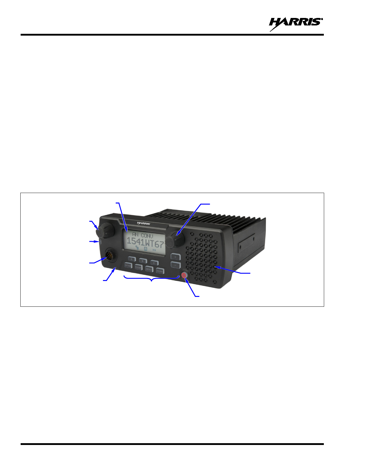
5.1 GENERAL DESCRIPTION
The XG-25M mobile radio is a high-performance digital mobile radio. It can operate in Project 25 (P25)
conventional and analog conventional modes. The XG-25M is considered a front-mount radio, since its
control head is an integral part of the radio. The head cannot be mounted separately from the radio.
The radio’s integrated control head features a large text and graphics-based liquid-crystal display (LCD),
and front panel controls for user control of the radio.
The XG-25M radio is designed to operate in a mobile environment, typically within a motor vehicle. It
must be connected to an external transmit/receive antenna such as one mounted to the vehicle’s rooftop or
trunk lid. The radio’s transmit output power is rated at 50 watts, with the power level adjustable from 10
to 50 watts via radio programming.
The radio provides half-duplex voice and data communications. Voice communications are accomplished
via a “push-to-talk” (PTT) type microphone and an external speaker connected to the radio’s control head.
Figure 5-1: XG-25M Mobile Radio (Front View)
The XG-25M may be equipped with an optional built-in Global Positioning System (GPS) tracking
receiver. The GPS antenna can be integrated into the mobile transmit/receive antenna (i.e., a
“combination” antenna). Alternately, the GPS antenna can be located/mounted completely separate from
the mobile transmit/receive antenna.
The XG-25M exceeds many tough environmental specifications included within military standard
MIL-STD-810G, the radio industry standard TIA/EIA-603, and the radio standard established by the U.S.
Forest Service.
The radio supports operation on APCO Project 25 compliant Common Air Interface (P25 CAI) radio
networks, and operation in a talk-around mode in accordance with the APCO Project 25. P25 radio
systems utilize Improved Multi-Band Excitation (IMBE) speech and data compression technology,
developed by Digital Voice Systems, Inc.
Power On/Off/Volume
Control
Microphone
Connector
Transmit/Receive
Indicator
Speaker
(Internal)
Home/Emergency Button
Menu Control, Scan,
and Preset Buttons
Front Panel
Group/Channel Control
Display

14221-1510-2000
19
Harris recommends the buyer use only an authorized representative to install and
service this product. The warranties provided to the buyer under the terms of sale shall
be null and void if this product is installed or serviced improperly, and Harris shall have
no further obligation to the buyer for any damage caused to the product or to any person
or personal property.
5.2 RELATED PUBLICATIONS
The following publications contain additional information about the XG-25M mobile radio:
•
Quick Guide:
14221-1510-1000
•
Installation and Product Safety Manual:
14221-1510-4000
These two (2 publications are included with each mobile radio equipment package when it ships from the
factory. The Quick Guide and this Operator’s Manual are available at www.pspc.harris.com without a
login. Obtaining the Installation and Product Safety Manual from that web site requires an Information
Center log-in, then browsing to Tech Link’s Technical Manual Library.
5.3 REPLACEMENT PARTS
Replacement parts can be ordered via our Customer Care center. To order replacement parts, call, fax or
e-mail:
United States:
• Phone Number: 1-800-368-3277
• Fax Number: 1-321-409-4393
• E-mail: PSPC_CustomerFocus@harris.com
International:
• Phone Number: 1-434-455-6403
• Fax Number: 321-409-4394
• E-mail: PSPC_InternationalCustomerFocus@harris.com
CAUTION
14221-1510-2000
20
6 CONTROLS AND INDICATORS
This section describes the controls and indicators located on the radio’s front panel.
6.1 POWER ON/OFF/VOLUME CONTROL
As illustrated in Figure 5-1 on page 18, the radio’s Power On/Off/Volume control is located on the top-
left corner of the display, as viewing the radio’s front panel. To turn on the radio, rotate this control
clockwise out of the detent position. To turn the radio off, rotate this control fully counter-clockwise until
it returns to the detent position, as sensed by a click of the control. See Section 7.1 for additional
information.
6.2 GROUP/CHANNEL CONTROL
The radio’s Group/Channel control is located just to the right of the display, as viewing the radio’s front
panel. See Figure 5-1 on page 18. By default per radio programming, this control selects groups or
channels in the currently selected system.
The radio may be programmed so this control selects systems instead of groups/channels. If so, the + and
– buttons are used to select groups/channels.
6.3 BUTTONS
Ten (10) buttons are located on the front panel of the radio. Button functions are summarized in Table
6-1.
Table 6-1: Button Functions
BUTTON FUNCTION
MENU
Primary Function:
Accesses the menu. This is a list of addition features that are not available
directly from the keypad.
Secondary Function: Activates a selected item within the menu, similar to an “Enter” key.
+ and –
Primary Function:
Scrolls through available systems, groups, or channels, depending on radio
programming.
Secondary Function: Changes the selection to another item in a menu list.
CLEAR
When
the menu function is active, press this button to cancel the current menu operation and
remove all displays associated with the menu.
When operating in conventional mode, press this button
briefly to disable radio receiver squelch,
so activity on the selected channel can be monitored. When pressed and held for approximately
three (3) seconds, this button toggles conventional channel decoding (Channel Guard, Digital
Channel Guard, T99) on and off, if programmed for the selected channel.
OPTION Activates one of any programmable software options selected during radio programming
. For
example, high or low transmitter power.
SCAN
Toggles scan operation on and off.
A, B and C The A, B and C preset buttons provide pre-
programmed for one of many available functions. In
this case, the function is activated by pressing the respective preset button.
Home/Emergency
button. If programmed as a home button, when pressed, the radio will
immediately transition to a pre-programmed home group/channel.
If programmed as an emergency button, hold it depressed for a short time to initiate and transmit
an emergency call request. The exact depression time is programmable. See Section 9.6
for
additional information.
14221-1510-2000
21
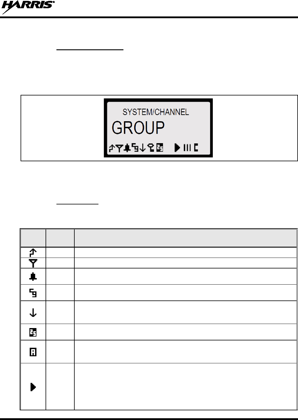
6.4 DISPLAY
6.4.1 General Information
The XG-25M radio has a tough high-contrast alphanumeric liquid-crystal display (LCD) that indicates
radio statuses and various operations. See Figure 5-1. When not in a menu selection mode, two text lines
in the upper and middle portion of the display provide quick indication of the selected system and
group/channel. Status icons in the lower portion turn on to indicate various functions are active/enabled.
During menu operations, the display indicates menu items/selections.
Figure 6-1: XG-25M Display (Generalized)
The radio’s display and buttons are backlit. Backlight intensity and display contrast adjustments can be
performed according to the procedures in Sections 7.4 and 7.5 respectively.
6.4.2 Status Icons
Status icons that appear in the bottom of the radio’s display are summarized in Table 6-2.
Table 6-2: Status Icons
ICON ICON
NAME STATUS/MEANING
Transmit The radio is transmitting.
Busy Indicates a “busy” condition—the radio receiving a call.
Type 99 The selected analog channel has Type 99 (T99) signaling enabled. See Section 9.5
on page
34 for additional information.
Channel
Guard The selected analog channel has Channel Guard signaling enabled.
Low
Transmit
Power
The radio is set will transmit in low power mode.
High/Low transmit power level is
programmable on a per channel basis. See Section 7.8 on page 25 for additional information.
P25 A Project 25 (P25) system and group/channel are selected.
The radio is operating in P25
mode. See Section 8 on page 28 for additional information.
Analog
Channel
Icon
An analog conventional system and channel are selected The radio is operating in an analog
conventional mode. See Section 9 on page 31 for additional information.
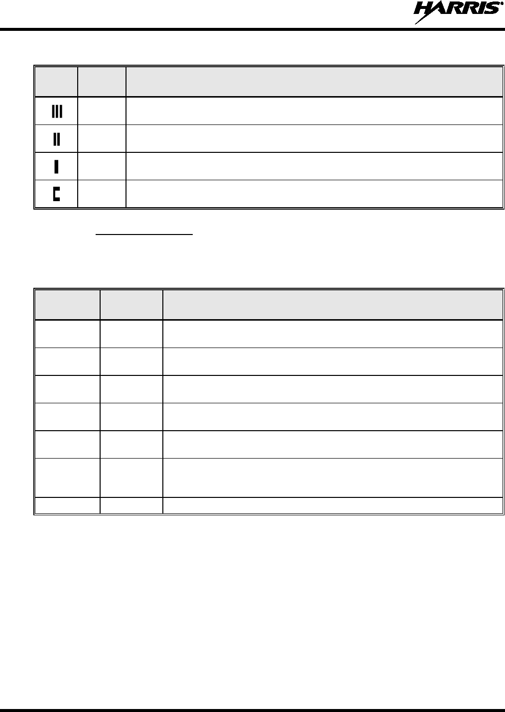
Scan Icon
When on with animated rotation, scan mode is enabled. The radio is scanning groups on the
list, including the Priority 1 and Priority 2 groups.
When
on steady without animated rotation, scan is temporarily disabled because the radio is
receiving a call on a scanned group.
When off (i.e., icon not appearing in the display), scan is disabled. The radio is not scanning.
See Section 9.3 on page 32 for additional information.
14221-1510-2000
22
Table 6-2: Status Icons
ICON ICON
NAME STATUS/MEANING
Scan Icon The selected group/channel is on the scan list as a non-priority group/channel
. The
group/channel will be scanned when the radio is scanning.
Scan
Priority 2 The selected group/channel is on the scan list as the Priority 2 group/channel.
When the
radio is scanning, it will be scanned with second highest priority.
Scan
Priority 1 The selected group/channel is on the scan list as the Priority 1 group/channel.
When the
radio is scanning, it will be scanned with highest priority.
Special
Call This icon appears when the radio is in special call mode. See Section 8.2 on page 28
for
additional information.
6.4.3 Status Messages
During radio operations, various status messages can appear in the radio’s display. These messages are
listed and described in the following table.
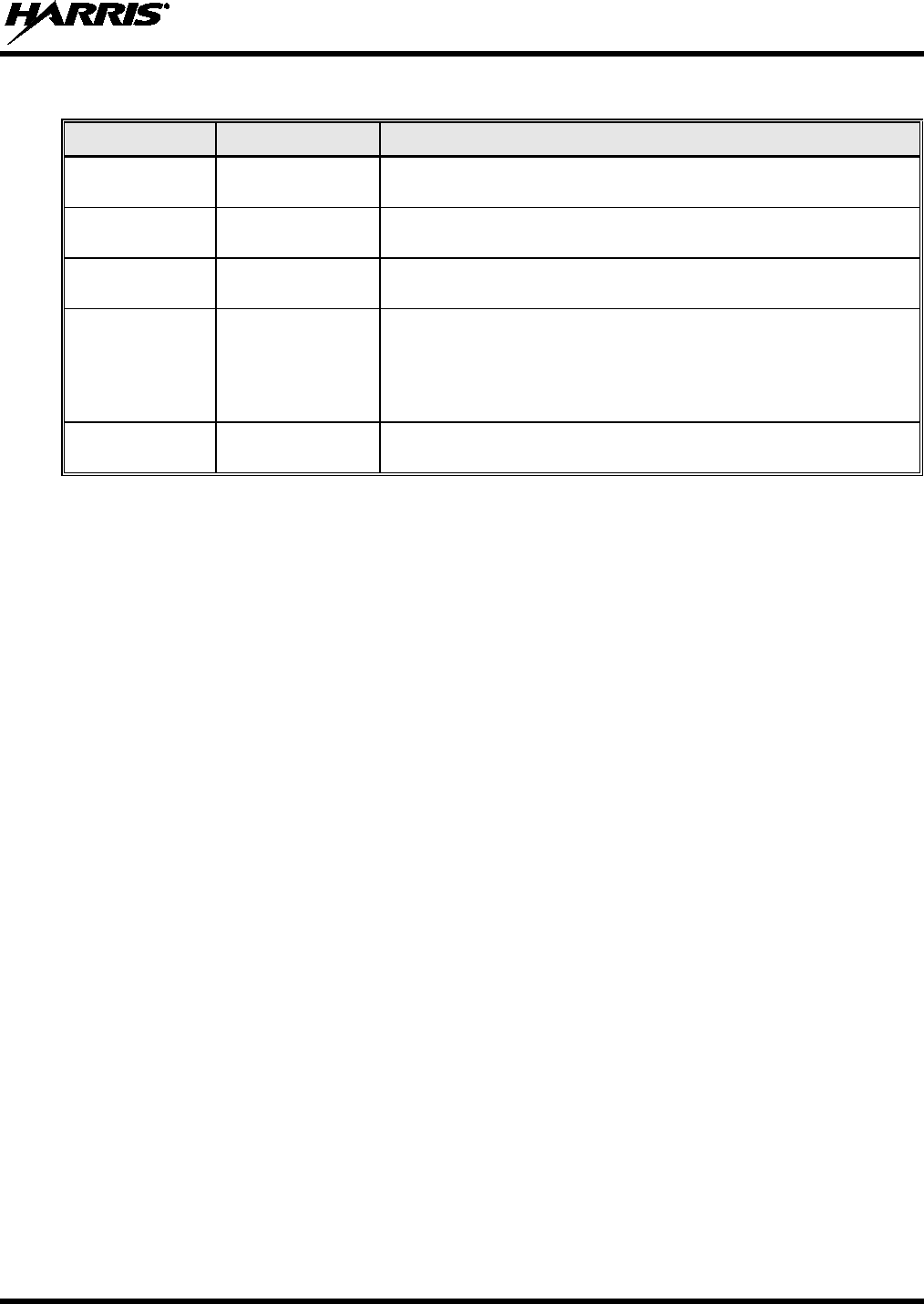
Table 6-3: Status Messages
MESSAGE MESSAGE
NAME DESCRIPTION
SYS BUSY System Busy
Indicates the radio system is busy, no channels are currently available, the queue is
full, or an individual call is being attempted to a radio that is currently transmitting.
DENIED Call Denied
Indicates the radio or talkgroup is not authorized to operate on the selected system
or talkgroup.
RXEMER Receive
Emergency When an emergency call is being received, this message flashes.
TXEMER Transmit
Emergency When an emergency call has been transmitted from this radio, this message flashes.
VOL=xx Volume
Level
Indicates the current volume level setting for receive audio. The volume level
indications range from OFF (muted) to 40 (loudest).
WHC Who Has
Called
Indicates
an individual call has been received, but not responded to. The indicator
turns off if the individual call mode is entered, the system is changed, or the radio is
turned off and then on again.
UNKNOWN Unknown ID Indicates an individual call is being received from an unknown ID.
6.5 TRANSMIT/RECEIVE INDICATOR
As indicated in Figure 5-1, the radio’s Transmit/Busy indicator is located on the left side of the radio’s
front panel. This indicator lights green when the radio is receiving a signal and it lights red when the radio
is transmitting.
6.6 ALERT TONES
The XG-25M mobile radio provides audible alert tones (“beeps”) to indicate various operating conditions.
These tones are listed and described in Table 6-4.
14221-1510-2000
23
Table 6-4: Alert Tones (“Beeps”)
NAME TONE MEANING
Call Originate 1 short mid-pitched After pressing the microphone’s Push-To-
Talk (PTT) to transmit, this
tone sounds to indicate it is OK to start talking into the mic.
System Busy 3 low-pitched
Sound after the PTT button is pressed to indicate the attempted
transmission did not occur because the radio system is too busy.
Call Denied 1 low-pitched
Sounds to indicate the radio is not authorized to transmit on the system
or group.
Carrier Control
Timer
5 high-pitched
followed by 1 long
low-pitched
Sounds if the programmed time for continuous transmission is
exceeded. The transmitter shuts down shortly after this alert
tone
sounds, interrupting communications. Release and re-
key the PTT
button to maintain communications. This resets the carrier contr
ol timer
and turns the transmitter back on.
Key Press Alert 1 short low-pitched
This tone indicates a key has been pressed. It i
ndicates no action was
taken because the key is not active in the current mode.

14221-1510-2000
24
7 COMMON OPERATIONS
7.1 TURNING THE RADIO ON AND OFF AND ADJUSTING VOLUME
To turn on the radio, rotate its Power On/Off/Volume control clockwise out of the detent position. Some
radio installations may be wired so an external switch such as the vehicle’s ignition key must also be
placed in a run or on position before the radio will turn on. When the radio is on, indications appear in the
display, such as the selected group/channel and status icons.
Rotate this control further clockwise to increase the volume of receive audio and rotate it counter-
clockwise to decrease the volume. Volume adjustment can be made at anytime during radio operation, as
needed.
To turn the radio off, rotate this control fully counter-clockwise until a click is sense. After this action, the
radio completely turns off within a few seconds.
7.2 CONNECTING A MICROPHONE (“MIC”)
As shown in Figure 5-1, the microphone connector is located near a bottom corner of the radio’s front
panel. Connect a microphone to this connector by positioning the small notch of the mic plug to a
straight-up (12-oclock position) at the mic connector, and then gently push the plug into the connector.
Finally, latch the plug to the connector by rotating the plug’s locking ring in a clockwise direction.
7.3 LOCKING AND UNLOCKING FRONT PANEL BUTTONS
The buttons on the front panel can be disabled to prevent accidental activation by “locking” them.
Locking and unlocking is a toggle-type function. To lock the buttons:
1. Press the MENU button to activate the menu function.
2. Within one (1) second, press the OPTION button.
To unlock the buttons, simply repeat the process.
Locking and unlocking can also be performed with the KEY LOCK menu item. See Section 7.9 for
additional information.
7.4 DISPLAY AND BUTTON BACKLIGHT ADJUSTMENT
If the backlight adjustment menu item is programmed on the radio’s menu, backlight intensity level can
be adjusted as follows:
1. Press the MENU button to activate the menu function.
2. Press the + or – buttons to until BACKLGHT (for backlight) appears in the display.
3. Press the MENU button again to select the backlight menu.
4. Press the + or – buttons to select a new backlight intensity level. Selections are OFF (no
backlighting) and 1 though 6, with 6 being the brightest backlight intensity level.
5. Press the MENU button again to save the new backlight intensity level and return to a normal
group/channel display indication.

14221-1510-2000
25
7.5 DISPLAY CONTRAST ADJUSTMENT
If the contrast adjustment menu item is programmed on the radio’s menu, the display contrast level can be
adjusted as follows:
1. Press the MENU button to activate the menu function.
2. Press the + or – buttons to until CONTRAST appears in the display.
3. Press the MENU button again to select the contrast menu.
4. Press the + or – buttons to select a new contrast level between 1 and 4.
5. Press the MENU button again to save the new contrast level and return to a normal group/channel
display indication.
7.6 SYSTEM SELECTION
Several different system selection methods exists based upon radio programming.
7.6.1 +/– Buttons Select System
If the + and – buttons are pre-programmed for radio system selection, when the radio is at a normal
group/channel display (i.e., not in a menu), press either button to select a different system. The name of
the selected system appears in the top line of the radio’s display.
7.6.2 Group/Channel Control Selects System
If the Group/Channel control is pre-programmed for radio system selection, rotate this control to select a
different system. The name of the selected system appears in the top line of the display.
7.7 GROUP/CHANNEL SELECTION
Several different group/channel selection methods exists based upon radio programming.
7.7.1 Group/Channel Control Selects Groups/Channels
If the Group/Channel control is pre-programmed for group/channel selection, rotate this control to select a
different group or channel. The name of the selected group/channel appears in the middle line of the
display.
7.7.2 +/– Buttons Select Groups/Channels
If the + and – buttons are pre-programmed for group/channel selection, when the radio is at a normal
group/channel display (i.e., not in a menu), press either button to select a different group/channel. The
name of the selected group/channel appears in the middle line of the radio’s display.
Any radio button may be pre-
programmed for system or group/channel selection.
Consult with the radio system’s network administration personnel for programming
information for a specific radio.
7.8 TRANSMIT POWER LEVEL ADJUSTMENT
Using low transmit power level, when possible, can help reduce or prevent unnecessary radio interference
on nearby radio frequencies. If the TX POWER menu item is pre-programmed into the radio, the radio’s
transmit power level can be switched between low and high as follows:
NOTE
14221-1510-2000
26
When the low transmit power level is selected, the status icon appears in the display.
The set power level is maintained after a channel change and after a system change.
7.8.1 Tx Power Adjustment via the Menu
1. Press the MENU button to activate the menu function. The programmed menu items appear in the
display. The > symbol at the left of a menu item indicates the currently selected menu item.
2. Press the + or – buttons to scroll until TX POWER is selected with the > symbol.
3. Press the MENU button again to toggle the transmit power level to the other level. For example, if the
radio was in the high power level, it will transition to a low power level.
7.8.2 Tx Power Adjustment via a Pre-Programmed Button
Any button on the radio’s front panel can be pre-programmed to toggle the transmit power level when it is
pressed. Typically, one of the three (3) preset buttons (A, B or C) is pre-programmed with this function. If
so, simply press the button to toggle the power level between low and high. The status icon appears in
the display when low transmit power level is selected.
7.9 MENU OPERATIONS
The radio’s menu function accesses features that are not directly available directly by a single button
stroke. Menu items available and the order of menu items are configurable via radio programming. They
are listed and described in Table 7-1. The menu item that is at the top of the programmed menu list will
always be displayed first. Subsequent access to the menu function will return the last menu item that was
shown in the display and cursor position. Basic menu operation is:
1. Press the MENU button to activate the menu function. The programmed menu items appear in the
display. The > symbol at the left of a menu item indicates the currently selected menu item.
The radio continues to receive and transmit as normal when the menu function is active.
2. Press the + or – buttons to scroll though menu items with the > symbol until the desired menu item is
selected, then press the MENU button again to select this item.
3. Press the + or – buttons to scroll though selections within this menu item.
4. When the desired selection is indicated, press the MENU button again to store this selection.
The TX POWER menu item, when selected, toggles between high and low transmit
power. It does not use the + or – buttons nor is an additional press of the MENU button
required.
NOTE
NOTE
NOTE
14221-1510-2000
27
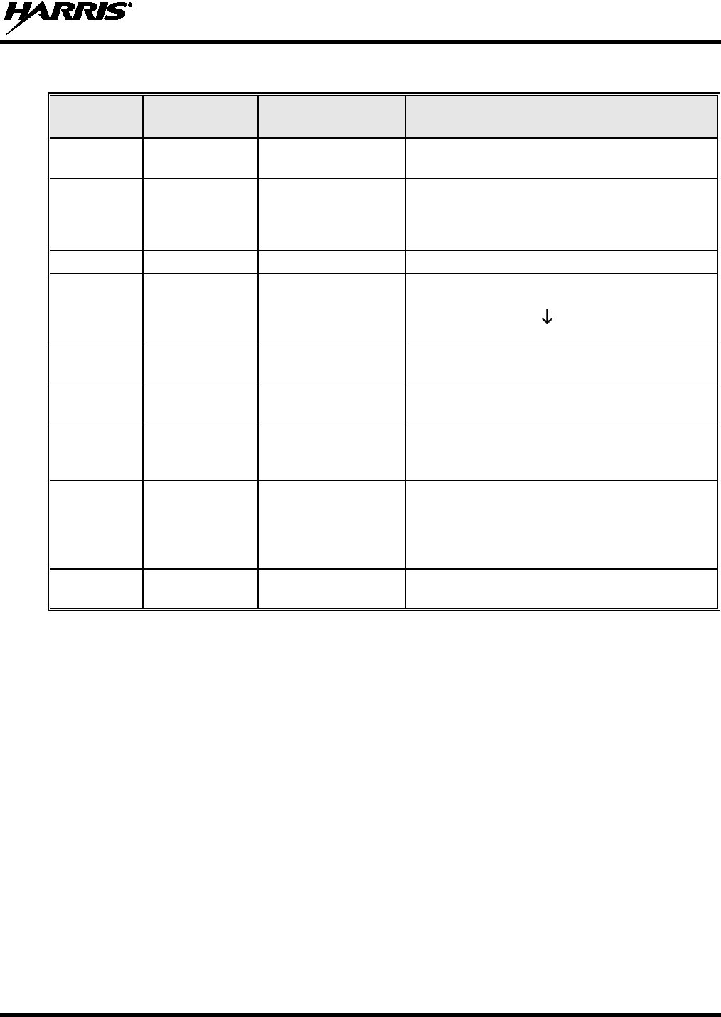
Table 7-1: Menu Items (Programmable)
DISPLAYED
NAME FEATURE RANGE DESCRIPTION
BACKLGHT Display and
Button Backlight OFF and 1 through 6 Use to
adjust the brightness level of display and
button backlighting.
KEY LOCK Keypad/ Button
Lock Locked, Unlocked
Use to lock and unlock radio buttons. As a short-
cut
(i.e., selecting this menu item is not necessary), press
the MENU
button then within one (1) second, press
the OPTION button.
CONTRAST Display Contrast 1 through 8 Use to adjust the contrast level of display.
TX POWER Transmit Power
Level High and Low
Use to toggle the radio’s transmit power level
between high and low. When the low transmit
power
level is selected, the
status icon appears in the
display.
REVISION Radio Revision
Information (n/a)
Selecting this menu item displays the revision of the
radio’s firmware.
PHONE Phone Call (list of 10 pre-stored
numbers)
Accesses the radio’s phone call list. Up to ten (10)
numbers can be pre-stored for auto-dialing.
EXT SPKR External Speaker On, Off Use to enable and disable an optional external/remote
speaker connected to the radio.
This speaker could be
located either inside or outside of the vehicle.
FEATURES Features List (n/a)
Indicates current features programmed into the radio
(e.g., P25 operation)
as well as certain information
required to add features to the radio
, such as the
radio’s serial number. Use the + and –
buttons to
scroll.
FCC MENU FCC/Service
Menu (n/a) Indicates various radio system engineering-
related
parameters.
7.10 MACRO KEYS
Macro key operation permits the user to accomplish a series of keystrokes with a single “macro”
keystroke. Each Macro Key is capable of executing up to twenty (20) keystrokes. Each macro key can be
pre-programmed to activate when pressed or when released. A macro key can also be pre-programmed to
change the key stroke sequence the next time the macro key is activated.
For detailed operation and assignment of macro keys, contact your communications supervisor or
administrator.

14221-1510-2000
28
8 P25 CONVENTIONAL OPERATIONS
8.1 GROUP CALLS IN P25 CONVENTIONAL MODE
8.1.1 Receiving a Group Call
1. If not already, turn the radio on by rotating the Power On/Off/Volume control clockwise out of its
detent position. The radio’s display activates and if enabled through programming, a short alert signal
sounds to indicate the radio is ready to use.
2. Select the desired P25 conventional radio system. Refer to Section 7.6 as necessary. The currently
selected system is indicated in the top line of the display.
3. Select the desired group. Refer to Section 7.7 as necessary. The currently selected group is indicated
in the middle line of the display. The radio is now ready to receive calls on the group. It unmutes
according to the squelch mode defined by radio programming (monitor, normal, selective).
4. When the radio receives a group call, it unmutes, GR and the calling radio’s unit ID or the group’s
name appears in the display. Also, the Transmit/Receive indicator lights green.
5. If necessary, make a volume adjustment by rotating the Power On/Off/Volume control.
8.1.2 Transmitting a Group Call
1. If not already, turn the radio on by rotating the Power On/Off/Volume control clockwise out of its
detent position. The radio’s display activates and if enabled through programming, a short alert signal
sounds to indicate the radio is ready to use.
2. Set the radio to receive calls on the desired P25 conventional system and talk group per the previous
section.
3. When the group is clear, press and hold the PTT button.
4. After the call originate tone sounds (a short mid-pitched beep), begin speaking into the controller’s
microphone. When speaking, hold the controller so its microphone is approximately 1-½ inches from
the mouth. Some radios may be programmed without a call originate tone. If so, pause a short time
after depressing the PTT button before beginning to speak.
5. Release the PTT button when the transmission is complete and listen for a reply.
6. Repeat transmissions as necessary.
8.2 INDIVIDUAL CALLS IN P25 CONVENTIONAL MODE
8.2.1 Receiving and Responding to an Individual Call
An individual call is a unit-to-unit radio call. When the radio receives an individual call from another
radio unit, it unmutes and displays the (Busy) status icon. The display shows the logical ID number of
the radio unit sending the message, or the associated radio unit name if the ID number is present in the
radio’s programmed individual call list.
The radio can be programmed to ring when an individual call is received. If so, the ring begins five (5)
seconds after the caller unkeys and it will continue until the microphone’s PTT button is pressed, the
CLEAR button is pressed, or the individual call mode is entered. The volume level of the ring is
adjustable via the radio’s Power On/Off/Volume control.

14221-1510-2000
29
If a response is made to the call by pressing the microphone’s PTT button prior to expiration of the pre-
programmed call-back time-out period, the call will be automatically directed to the originating unit via
an individual call. If a response is not made before the call-back time-out period expires, the radio will
return to normal receive display, and *WHC* (Who Has Called) will appear in the display.
To respond after expiration of the call-back time-out period, press the pre-programmed Individual Call
function key (if programmed) or access this function via the menu. The radio’s display will show the
caller’s ID and WHCI=1. At this point, pressing the microphone’s PTT button will initiate an individual
call back to the original caller.
Pressing the microphone’s PTT button will initiate an individual call to the displayed logical ID.
Powering the radio off and on will clear this list.
The basic procedure to receive an individual call on a P25 conventional radio system is:
1. If not already, turn the radio on by rotating the Power On/Off/Volume control clockwise out of its
detent position. The radio’s display activates and if enabled through programming, a short alert signal
sounds to indicate the radio is ready to use.
2. Select the desired P25 conventional radio system. Refer to Section 7.6 as necessary. The currently
selected system is indicated in the top line of the display.
3. The radio is now ready to receive group and individual calls. It unmutes according to the squelch
mode defined per radio programming (monitor, normal, selective).
4. When the radio receives a P25 individual call, it unmutes and the unit ID/alias of the calling (i.e.,
transmitting) radio appears in the display.
5. Rotate the Power/On/Off/Volume control to adjust the radio to desired volume level.
6. Press the PTT button to respond to the caller.
Unanswered individual calls appear in the Who Has Called (WHC) list.
8.2.2 Transmitting an Individual Call
1. Press the MENU button to activate the menu function. The programmed menu items appear in the
display. The > symbol at the left of a menu item indicates the currently selected menu item.
2. Select the desired radio unit for calling from either the Calls Received List (WHCI1 through
WHCI10) or a pre-stored unit via the Individual Call (INDV) menu function (if programmed).
To select a pre-stored unit (if programmed) from the Individual Call menu, scroll through the list of
pre-stored phone numbers using the + or - buttons until the desired ID number or unit name is
displayed, the press the MENU button.
3. Press the microphone’s PTT button. When the radio is clear to transmit turns on, turns off, and
the channel access tone sounds. Line one shows the called individual's name or LID. *INDV*
displays.
8.3 STATUS OPERATIONS
The Status feature allows for the transmission of a pre-programmed status. Each status is assigned an ID
that is cross-referenced with the representative status condition (for example, “Off Duty”) in the radio
system.
1. Press the MENU button to activate the menu function. The programmed menu items appear in the
display. The > symbol at the left of a menu item indicates the currently selected menu item.

14221-1510-2000
30
2. Press the + or – buttons to scroll through the menu items to select one (1) of ten (10) possible pre-
programmed status message, identified as STATUS 1 through STATUS 9.
3. When the desired status is selected, press the MENU button again to transmit this status. If no status
has been programmed for the selected number key, the radio will display NO ENTRY. A valid
selection will display the status for a pre-programmed time.
4. After the time-out expires or the MENU button has been pressed (this button overrides the time-out
period), the status is selected and it will be transmitted to the radio system or stored in the radio
memory where it can be polled by the radio system for a future transmission.
View the currently selected status after it has been transmitted by pressing the MENU button twice and
then the CANCEL button prior to the time-out period. If the status was not sent successfully to the site,
the text associated with the status condition will flash in the display.
The status selection can be changed by pressing a different status key or the status operation can be
cancelled by pressing the CANCEL button. In either case, this must be performed before the time-out
period expires.
14221-1510-2000
31
9 ANALOG CONVENTIONAL OPERATIONS
This section describes operations when an analog conventional radio system is selected.
9.1 RECEIVING A CALL IN ANALOG CONVENTIONAL MODE
Follow this basic procedure to receive a call:
1. If not already, turn the radio on by rotating the Power On/Off/Volume control clockwise out of its
detent position. The radio’s display activates and if enabled through programming, a short alert signal
sounds to indicate the radio is ready to use.
2. Select the desired analog conventional radio system. Refer to Section 7.6 as necessary. The currently
selected system is indicated in the top line of the display.
3. Select the desired channel. Refer to Section 7.7 as necessary. The currently selected channel is
indicated in the middle line of the display. The radio is now ready to receive calls on the channel.
4. When the radio receives a call (and the correct encoding is decoded, if programmed and enabled), it
unmutes on the channel, the (Busy) status icon appears in the display, and the Transmit/Receive
indicator lights green to visually indicate the presence of the call on the channel.
Optional: Press the CLEAR button to disabled squelch and monitor any calls on the channel (with or
without signaling).
5. If necessary, make a volume adjustment by rotating the Power On/Off/Volume control.
9.2 TRANSMITTING A CALL IN ANALOG CONVENTIONAL MODE
Follow this basic procedure to receive a call:
1. If not already, turn the radio on by rotating the Power On/Off/Volume control clockwise out of its
detent position. The radio’s display activates and if enabled through programming, a short alert signal
sounds to indicate the radio is ready to use.
2. Select the desired analog conventional radio system. Refer to Section 7.6 as necessary. The currently
selected system is indicated in the top line of the display.
3. Select the desired channel. Refer to Section 7.7 as necessary. The currently selected channel is
indicated in the middle line of the display. The radio is now ready to receive calls on the channel.
4. Verify the channel is not busy (i.e., no call currently exists on it) by observing for the lack of the
(Busy) status icon in the display. If this icon is present in the display, do not proceed until it
disappears.
For an analog convention channel, a channel’s busy/not busy status can also be checked
by briefly depressing the radio’s CLEAR button. This disables squelch and any channel
pre-programmed decoding and unmutes the receiver.
If the Channel Busy Lockout feature is programmed for the selected channel, the radio
will not transmit when the channel is busy
5. Press and hold the microphone’s PTT button. If the Call Originate (sometimes call Ready-To-Talk)
alert tone is programmed, the radio will sound a short beep tone when it begins transmitting on the
channel.
NOTE
NOTE
14221-1510-2000
32
6. Hold the microphone approximately 1-½ inches from the mouth and speak into it in a normal voice.
7. When the transmission is complete, release the PTT button and listen for a reply.
8. Repeat transmissions as necessary.
9.3 SCANNING CHANNELS IN ANALOG CONVENTION MODE
Channels which have been previously added to the scan list on a per system basis, can be scanned. The
selected channel is scanned (if enabled through programming) whether or not it is in the scan list. Each
conventional system’s channel scan list is retained in memory when the radio is turned off.
The scan rate varies depending upon the number of channels in the scan list and whether or not the radio
is programmed to scan for channels with decoding enabled. Fewer channels results in a faster scan rate. If
programmed for dual-priority scan operation, the priority 1, priority 2, and the remaining scan list
channels are scanned. Once a signal is detected and the correct encoded squelch signal is decoded (if
programmed), the radio receives the message and displays the received scan channel. At the same time,
scanning continues on the priority 1 and priority 2 channels. If a priority 1 or priority 2 channel carrier,
regardless of encoded squelch decoding, is detected while a non-priority channel is being received, the
display name is updated and the received channel is switched to the priority channel. Scanning of the
priority 1 channel continues if a message is being received on the priority 2 channel.
While receiving a call on a non-priority or a priority 2 channel, the radio periodically checks the priority 1
and 2 channels. If scan with Channel Guard is enabled, the radio uses Channel Guard to decide whether to
unmute on a priority channel. The radio stops, on squelch detection, on a priority channel. In normal
operation, the radio unmutes only on detecting the correct Channel Guard; otherwise, it remains muted
until the priority channel call and hang time have ended. An optional feature allows the radio to continue
scanning upon the detection of the wrong Channel Guard on a priority channel. The user can then select
the rate at which this channel is scanned until the call ends.
9.3.1 Turning Scan On and Off
Toggle scan operation on and off by pressing the SCAN button. The (Scan) icon rotates in the bottom
line of the display when the radio is scanning.
Scanning stops when the radio is receiving or transmitting a call. Scanning also stops
while the microphone is off-hook,
if the hookswitch feature is enabled through
programming.
When a channel on the scan list has an active call, the radio unmutes, the Transmit/Busy indicator lights
green, and the call is heard in the radio’s speaker/headset.
The radio continues scanning if a new channel is selected when scan is on.
Pressing the PTT button when scan is on causes the radio to transmit on the displayed channel or on the
currently selected channel, depending on programming.
When scan is turned off, the radio resumes operation on the selected channel.
9.3.2 Adding Channels to the Scan List
If the radio’s conventional menu is programmed with the Scan Add feature, a channel in the currently
selected system can be added to the scan list as follows:
1. When the radio is scanning, the (Scan) icon rotates in the bottom line of the display. In this case,
turn scan off by pressing the SCAN button once.
NOTE
14221-1510-2000
33
2. Select the desired channel to be added to the scan list.
3. Press the MENU button to activate the menu function.
4. Press the + or – buttons to scroll through the menu items until SCAN ADD is selected with the
> symbol.
5. Press the MENU button again to add the channel to the scan list. Scan priority icon (3 bars)
displays. This sets the selected channel for scanning, but as a non-priority channel. The radio returns
to a normal display with the non-priority scan icon displayed.
6. Optional: Press the MENU button again to set the group for Priority 2 (P2) scan. Scan priority icon
(2 bars) displays.
7. Optional: Press the MENU button again to set the group for Priority 1 (P1) scan. Scan priority icon
(1 bar) displays.
If the P1 or P2 channels are already set and a new channel is then assigned as the P1 or P2 channel, the
previously assigned priority channel changes to non-priority scanning on the scan list. The priority setting
selection sequence is set and stops at P1, therefore the channel must be deleted from the scan list before
the channel is set to a previous priority setting. When it is the selected channel, a channel that is in a
system’s channel scan list displays the respective scan priority icon (3 bars) for scan but no priority,
(2 bars) for scan with priority 2, or (1 bar) for scan with priority 1.
8. To add additional channels, repeat from step 2.
9. Press the CLEAR button to exit the menu and return to a normal display.
9.3.3 Deleting Channels from the Scan List
1. When the radio is scanning, the (Scan) icon rotates in the bottom line of the display. In this case,
turn scan off by pressing the SCAN button once.
2. Select the desired channel to be deleted from the scan list.
3. Press the MENU button to activate the menu function.
4. Press the + or – buttons to scroll through the menu items until SCAN DEL is selected with the
> symbol.
5. Press the MENU button again to delete the channel from the scan list. The scan priority icon
disappears from the display. If the channel was not previously on the scan list and if alert tones are
programmed on, the key press alert tone (one short low-pitched beep) sounds.
6. To add additional channels, repeat from step 2.
7. Press the CLEAR button to exit the menu and return to a normal display.
9.4 SQUELCH ADJUSTMENT IN ANALOG CONVENTIONAL MODE
In the conventional mode of operation, the radio’s receiver squelch setting can be adjusted via the menu
(if programmed) or via a button that has been pre-programmed with the Squelch function. The default
squelch setting is nine (9). Any setting between one (1) and sixteen (16) can be selected if the Squelch
function is available.
A setting of sixteen (16) requires a strong signal to open squelch, a setting of two (2)
requires a very weak signal to open squelch, and a setting of one (1) is open squelch.
NOTE
14221-1510-2000
34
When the squelch adjust feature is activated, Channel Guard, T99 decode, and Scan are
disabled. When the squelch adjust feature is exited, Channel Guard, T99 decode, and
Scan are restored to their previous states.
Use this procedure to adjust squelch:
1. Press the MENU button to activate the menu function.
Alternately, if another button such as one (1) of the three (3) present buttons is pre-programmed with
the Squelch function, press this button and advance to step 3.
2. Press the + or – buttons to scroll through the menu items until SQUELCH is selected with the
> symbol, and then press the MENU button again.
3. SQLCH=xx, where xx is the current squelch setting appears in the second line of the display. The
range is 1 to 16. Press the + or – buttons to increase or decrease the current squelch setting as
required. Higher settings require a stronger received signal to open squelch.
4. Press the MENU button again to save the new setting and return to a normal display. If the MENU
button is not pressed after a short period, menu selection automatically exits and the new squelch
setting is not saved. At any time, press the CLEAR button to cancel a change.
9.5 TYPE 99 DECODE IN ANALOG CONVENTIONAL MODE
9.5.1 General Information
Type 99 is a form of selective signaling. Selective signaling controls the muting and unmuting of receiver
audio via two-tone sequential signaling. Radio base stations, mobile radios or portable radios with Type
99 encode capability can selectively call individual radio units or groups of units in an analog
conventional radio system. Type 99 is typically used in paging operations so a dispatcher can selectively
call a radio or a group of radios. If Type 99 is enabled in via radio pre-programming, the radio can decode
individual, group, and supergroup Type 99 calls.
To support Type 99 decode operations, two (2) sets of Type 99 paging codes must be pre-programmed
into the radio. When the radio decodes an appropriate Type 99 code sequence, an alert tone and a visual
indication is provided to the user. The receiver then operates with noise squelched until Type 99 is reset.
Type 99 decode continues to operate during this noise squelched period. The appropriate Type 99 alert
tone sounds again if it detects a valid two-tone sequence.
Type 99 operation can be reset manually or automatically (pre-programmed). Manual reset is achieved by
briefly pressing the CLEAR button, if programmed. Automatic reset, if enabled, occurs after a thirty (30)
second interval following the most recent decode of a Type 99 tone sequence. Hookswitch (pre-
programmed) can also enable or disable Type 99 decode. The pre-programmed key light blinks when
Type 99 is disabled by the hookswitch.
Type 99 decode continues to be active while the CLEAR button is pressed. This allows the user to
monitor calls and still be alerted when a call is directed to the user. While the user continues to press the
CLEAR button, the user hears both calls and all Type 99 tone signals. If the CLEAR button is pressed for
longer than two (2) seconds, Type 99 decode is either disabled or re-enabled depending upon its present
state.
Type 99 is automatically disabled when Scan is enabled.
NOTE
NOTE

14221-1510-2000
35
9.5.2 Type 99 Enable/Disable via Menu Selection
If the Type 99 Enable function is programmed on the menu, use this procedure to toggle Type 99
decoding on or off via the menu.
1. Press the MENU button to activate the menu function.
Alternately, if another button such as one (1) of the three (3) present buttons is pre-programmed with
the Type 99 Enable function, press this button and advance to step 3.
2. Press the + or – buttons to scroll through the menu items until T99 EN is selected with the > symbol,
and then press the MENU button again.
3. Press the MENU button to toggle the Type 99 decode state between on and off. T99 ON or T99 OFF
displays, respectively, as the button is pressed.
When Type 99 is off, it is disabled and considered to be in the “monitor” state. When Type 99 is on, it is
enabled and considered to be in the “selective call” state.
9.5.3 Type 99 Enable/Disable via a Pre-Programmed Button
If a button is programmed to enable and disable Type 99 decoding, simply press that button to toggle
Type 99 decoding on or off. T99 ON or T99 OFF displays, respectively, as the button is pressed.
When Type 99 is off, it is disabled and considered to be in the “monitor” state. When Type 99 is on, it is
enabled and considered to be in the “selective call” state.
9.5.4 Type 99 With or Without Channel Guard
Selective signaling operates with or without Channel Guard. If Channel Guard is enabled, the radio can be
programmed with an “And” or an “Or” option, determined by programming with T99 Mute Control.
If the “And” option is programmed, T99 calls require the correct selective signaling (T99 tone sequence)
and the correct Channel Guard tones are heard by the user.
If the “Or” option is programmed, calls with the correct Channel Guard tones or calls with the correct T99
tone sequence and Channel Guard tones are heard by the user.
A radio operating in Type 99 selective call mode that receives a selective call switches to the monitor
mode (after decoding the T99 call) and the Transmit/Receive indicator flashes green.
9.5.5 Resetting Type 99 After a Decoded Call
Type 99 operation can be reset manually or automatically (pre-programmed). Manual reset is achieved by
briefly pressing the CLEAR button, if programmed. Automatic reset, if enabled, occurs after a thirty (30)
second interval following the most recent decode of a Type 99 tone sequence. Hookswitch (pre-
programmed) can also enable or disable Type 99 decode. The pre-programmed key light blinks when
Type 99 is disabled by the hookswitch.
9.5.6 Type 99 Disable After Radio PTT
The radio may be pre-programmed with the Type 99 Disable After PTT feature. This feature
automatically disables the Type 99 decoder after a radio transmission.

14221-1510-2000
36
9.6 EMERGENCY CALLS IN ANALOG CONVENTIONAL MODE
9.6.1 G-STAR Emergency Signalling
If enabled, G-STAR emergency signaling can be transmitted when operating in the analog conventional
mode. This G-STAR signaling transmits five (5) times with a delay between each transmission. To send
an emergency call on the selected analog conventional system and channel (or on an optionally pre-
programmed analog conventional emergency system and channel), proceed as follows:
Press and hold the red Emergency/Home button for approximately one second (this time is programmable
and, therefore, could be longer or shorter; check with the system administrator). The radio turns on the
Transmit/Busy indicator lights red and it proceeds to transmit the pre-programmed G-STAR emergency
signaling sequence.
G-STAR is programmed to transmit in one of the following methods:
Method 1: G-STAR is transmitted on the selected channel. If the channel is changed the emergency
signaling continues to be transmitted on the newly selected channel.
Method 2: Same as Method 1 except the radio locks on to the currently selected channel. Attempts to
change the system or channel are disabled.
Method 3: G-STAR is transmitted on a pre-programmed analog conventional emergency system and
channel regardless of the selected channel. In this case the selected channel is available for
voice transmission and the radio periodically changes to the pre-programmed emergency
system and channel to send the emergency signaling and then changes back to the selected
channel.
Method 4: Same as Method 3, except the radio locks on to the pre-programmed emergency system
and channel. Attempts to change the system or channel are disabled.
The emergency state can be cleared by turning the radio off and then back on.
9.6.2 5-Tone Emergency Signalling
If 5-tone emergency signaling is defined for emergency declaration in place of G-STAR emergency
signaling, a pre-programmed tone sequence is transmitted instead of the G-STAR sequence. This
emergency declaration functions as the G-STAR emergency in all other respects.
9.6.3 Tone Encode Transmission
In analog conventional mode, two keys can be defined to be tone encode triggers. If either one of the pre-
programmed tone encode triggers is pressed, a pre-programmed tone sequence is transmitted on the
current system and channel. See Section 9.6 if the Emergency/Home key is used. The Transmit/Busy
indicator lights red during the tone transmission and a beep sounds at the end of the transmission. If
enabled, audible side tones are heard in the radio speaker as well. If PTT is pre-programmed as one of the
triggers, the microphone becomes active for voice communication after the tone sequence is complete.
Tone encode is transmitted with Channel Guard if one is defined, and tones are always transmitted in
clear voice mode, even if the channel is set for digital or private. Digital or private voice transmission
resumes normally after the tone transmission.

14221-1510-2000
37
10 CUSTOMER SERVICE
10.1 CUSTOMER CARE
If any part of the system equipment is damaged on arrival, contact the shipper to conduct an inspection
and prepare a damage report. Save the shipping container and all packing materials until the inspection
and the damage report are completed. In addition, contact the Customer Care center to make
arrangements for replacement equipment. Do not return any part of the shipment until you receive
detailed instructions from a Harris representative.
Contact the Customer Care center at http://www.pspc.harris.com/CustomerService or:
North America:
• Phone Number: 1-800-368-3277
• Fax Number: 1-321-409-4393
• E-mail: PSPC_CustomerFocus@harris.com
International:
• Phone Number: 1-434-455-6403
• Fax Number: 1-321-409-4394
• E-mail: PSPC_InternationalCustomerFocus@harris.com
10.2 TECHNICAL ASSISTANCE
The Technical Assistance Center’s (TAC) resources are available to help with overall system operation,
maintenance, upgrades and product support. TAC is the point of contact when answers are needed to
technical questions.
Product specialists, with detailed knowledge of product operation, maintenance and repair provide
technical support via a toll-free (in North America) telephone number. Support is also available through
mail, fax and e-mail.
For more information about technical assistance services, contact your sales representative, or call the
Technical Assistance Center at:
• North America: 1-800-528-7711
• International: 1-434-385-2400
• Fax: 1-434-455-6712
• E-mail: PSPC_tac@harris.com
11 WARRANTY REGISTRATION
Please register this product within ten (10) days of purchase. Registration validates the warranty coverage,
and enables Harris to contact you in case of any safety notifications issued for this product.
Registration can be made on-line at http://www.pspc.harris.com/Service/WarrantySupport.asp.

14221-1510-2000
38
12 WARRANTY
A. Harris Corporation, a Delaware Corporation, through its RF Communications Division (hereinafter
"Seller") warrants to the original purchaser for use (hereinafter "Buyer") that Equipment manufactured
by or for the Seller shall be free from defects in material and workmanship, and shall conform to its
published specifications. With respect to all non-Seller Equipment, Seller gives no warranty, and only
the warranty, if any, given by the manufacturer shall apply. Rechargeable batteries are excluded
from this warranty but are warranted under a separate Rechargeable Battery Warranty (ECR-7048).
B. Seller’s obligations set forth in Paragraph C below shall apply only to failures to meet the above
warranties occurring within the following periods of time from date of sale to the Buyer and are
conditioned on Buyer’s giving written notice to Seller within thirty (30) days of such occurrence:
1. for fuses and non-rechargeable batteries, operable on arrival only.
2. for parts and accessories (except as noted in B.1 and B.5), ninety (90) days.
3. for XG-25P, XG-75, P7300, P7200, P7100IP, P5500, P5400, P5300, P5200, P5100, P3300,
M7300, M7200 (including V-TAC), M7100IP, M5300, M3300 and SG5300 radios, two (2) years,
effective 10/01/2007.
4. for Unity® XG-100P and XG-100M, three (3) years.
5. for Six-Bay battery Chargers (12082-0314-xx and CH-104570-xxx), one (1) year.
6. for all other equipment of Seller’s manufacture, one (1) year.
C. If any Equipment fails to meet the foregoing warranties, Seller shall correct the failure at its option (i)
by repairing any defective or damaged part or parts thereof, (ii) by making available at Seller’s factory
any necessary repaired or replacement parts, or (iii) by replacing the failed Equipment with equivalent
new or refurbished Equipment. Any repaired or replacement part furnished hereunder shall be
warranted for the remainder of the warranty period of the Equipment in which it is installed. Where
such failure cannot be corrected by Seller’s reasonable efforts, the parties will negotiate an equitable
adjustment in price. Labor to perform warranty service will be provided at no charge during the
warranty period only for the Equipment covered under Paragraph B.3, B.4 and B.5. To be eligible for
no-charge labor, service must be performed at Seller’s factory, by an Authorized Service Center
(ASC) or other Servicer approved for these purposes either at its place of business during normal
business hours, for mobile or personal equipment, or at the Buyer’s location, for fixed location
equipment. Service on fixed location equipment more than thirty (30) miles (48 km) from the Service
Center or other approved Servicer’s place of business will include a charge for transportation.
D. Seller’s obligations under Paragraph C shall not apply to any Equipment, or part thereof, which (i) has
been modified or otherwise altered other than pursuant to Seller’s written instructions or written
approval or, (ii) is normally consumed in operation or, (iii) has a normal life inherently shorter than the
warranty periods specified in Paragraph B, or (iv) is not properly stored, installed, used, maintained or
repaired, or, (v) has been subjected to any other kind of misuse or detrimental exposure, or has been
involved in an accident.
E. The preceding paragraphs set forth the exclusive remedies for claims based upon defects in or
nonconformity of the Equipment, whether the claim is in contract, warranty, tort (including
negligence), strict liability or otherwise, and however instituted. Upon the expiration of the warranty
period, all such liability shall terminate. The foregoing warranties are exclusive and in lieu of all other
warranties, whether oral, written, expressed, implied or statutory. NO IMPLIED OR STATUTORY
WARRANTIES OF MERCHANTABILITY OR FITNESS FOR PARTICULAR PURPOSE SHALL
APPLY. IN NO EVENT SHALL THE SELLER BE LIABLE FOR ANY INCIDENTAL,
CONSEQUENTIAL, SPECIAL, INDIRECT OR EXEMPLARY DAMAGES.
This warranty applies only within the United States.
Harris Corporation Harris Corporation
RF Communications Division RF Communications Division
221 Jefferson Ridge Parkway 1680 University Avenue
Lynchburg, VA 24501 Rochester, NY 14610
1-800-368-3277 1-585-244-5830
ECR-7047R