HARRIS TR-0077-E Mobile, XG-25 378-470 MHz 50W User Manual Safety
HARRIS CORPORATION Mobile, XG-25 378-470 MHz 50W Safety
HARRIS >
Contents
- 1. User Manual Operator
- 2. User Manual Safety
- 3. User Manual Intsallation
User Manual Safety

Product Safety Manual
14221-1510-4000
Rev. C, Mar/14
For radio installation information, refer to Installation Manual publication number 14221-
1510-4440, which is available on-line via Tech-Link, or as a printed manual. See page 32 for
additional information.
NOTE
XG-25M Mobile Radios
50-Watt VHF, 136 to 174 MHz
14015-0010-01,
50-Watt UHF, 378 to 470 MHz
14015-0030-01,
35-Watt Dual-Band, 700/800 MHz
14015-0020-01
Includes Front-Mount and
Remote-Mount Applications
14221-1510-4000, Rev. C
2
MANUAL REVISION HISTORY
REV. DATE REASON FOR CHANGE
– Aug/12 Initial release.
A May/13 Added 700/800 MHz radio. Removed installation information (see publication 14221-1510-4440).
B Oct/13 Revised regulatory information.
C Mar/14 Added 378 - 470 MHz UHF radio and the respective antenna MPE information.
Harris Corporation, Public Safety and Professional Communications (PSPC) Business, continually evaluates its technical
publications for completeness, technical accuracy, and organization. You can assist in this process by submitting your
comments and suggestions to the following:
Harris Corporation fax your comments to: 1-434-455-6851
PSPC Business or
Technical Publications e-mail us at: PSPC_TechPubs@harris.com
221 Jefferson Ridge Parkway
Lynchburg, VA 24501
ACKNOWLEDGEMENT
This device is made under license under one or more of the following US patents: 4,590,473; 4,636,791; 5,148,482;
5,185,796; 5,271,017; 5,377,229; 4,716,407; 4,972,460; 5,502,767; 5,146,497; 5,164,986; 5,185,795; 5,226,084; 5,247,579;
5,491,772; 5,517,511; 5,630,011; 5,649,050; 5,701,390; 5,715,365; 5,754,974; 5,826,222; 5,870,405; 6,161,089; and
6,199,037 B1. DVSI claims certain rights, including patent rights under aforementioned U.S. patents, and under other U.S.
and foreign patents and patents pending. Any use of this software or technology requires a separate written license from
DVSI.
CREDITS
Harris and assuredcommunications are registered trademarks of Harris Corporation.
All other brand and product names are trademarks, registered trademarks, or service marks of their respective holders.
NOTICE!
The material contained herein is subject to U.S. export approval. No export or re-export is permitted without written
approval from the U.S. Government. Rated: EAR99 in accordance with U.S. Dept. of Commerce regulations 15CFR774,
Export Administration Regulations.
Information and descriptions contained herein are the property of Harris Corporation. Such information and descriptions may
not be copied or reproduced by any means, or disseminated or distributed without the express prior written permission of
Harris Corporation, PSPC Business, 221 Jefferson Ridge Parkway, Lynchburg, VA 24501.
The voice coding technology embodied in this product is protected by intellectual property rights including patent rights,
copyrights, and trade secrets of Digital Voice Systems, Inc. The user of this technology is explicitly prohibited from
attempting to decompile, reverse engineer, or disassemble the Object Code, or in any other way convert the Object Code into
human-readable form.
Repairs to this equipment should be made only by an authorized service technician or facility designated by the supplier. Any
repairs, alterations or substitutions of recommended parts made by the user to this equipment not approved by the
manufacturer could void the user's authority to operate the equipment in addition to the manufacturer's warranty.
This product conforms to the European Union WEEE Directive 2002/96/EC. Do not dispose of this product in a
public landfill. Take it to a recycling center at the end of its life.
This manual is published by Harris Corporation without any warranty. Improvements and changes to this manual necessitated by typographical errors,
inaccuracies of current information, or improvements to programs and/or equipment, may be made by Harris Corporation
at any time and without notice.
Such changes will be incorporated into new editions of this manual. No part of this manual may be reproduced or t
ransmitted in any form or by any means,
electronic or mechanical, including photocopying and recording, for any purpose, without the express written permission of
Harris Corporation.
Copyright © 2012 — 2014, Harris Corporation

14221-1510-4000, Rev. C
3
TABLE OF CONTENTS
Section Page
1 REGULATORY AND SAFETY INFORMATION .................................................................... 5
1.1 SAFETY SYMBOL CONVENTIONS ................................................................................................. 5
1.2 RF ENERGY EXPOSURE AWARENESS AND CONTROL INFORMATION FOR FCC
OCCUPATIONAL USE REQUIREMENTS........................................................................................ 5
1.2.1 Federal Communications Commission Regulations ............................................................... 6
1.3 COMPLIANCE WITH RF EXPOSURE STANDARDS ...................................................................... 6
1.3.1 Mobile Antennas .................................................................................................................. 12
1.3.2 Approved Accessories .......................................................................................................... 12
1.3.3 Contact Information .............................................................................................................. 12
1.4 RADIO FREQUENCY INTERFERENCE ......................................................................................... 12
1.4.1 FCC Part 15 .......................................................................................................................... 12
1.4.2 Industry Canada .................................................................................................................... 13
1.5 OCCUPATIONAL SAFETY GUIDELINES AND SAFETY TRAINING INFORMATION ........... 13
1.6 COMMON HAZARDS ...................................................................................................................... 13
1.7 SAFE DRIVING RECOMMENDATIONS ........................................................................................ 14
1.8 OPERATING RULES AND REGULATIONS .................................................................................. 14
1.9 OPERATING TIPS ............................................................................................................................. 15
2 RENSEIGNEMENTS SUR LA RÉGLEMENTATION ET SÉCURITÉ ............................... 16
2.1 CONVENTIONS SUR LES SYMBOLES DE SÉCURITÉ ................................................................ 16
2.2 RENSEIGNEMENTS SUR UNE EXPOSITION À L’ÉNERGIE DES RF ........................................ 16
2.2.1 Renseignements Sur Le Contrôle Et La Sensibilisation À L’énergie Des RF Pour Les
Exigences D’une Utilisation Professionnelle De La FCC .................................................... 16
2.3 CONFORMITÉ AUX NORMES D’EXPOSITION AUX RF ............................................................ 17
2.3.1 Antennes mobiles ................................................................................................................. 24
2.3.2 Accessoires approuvés .......................................................................................................... 24
2.3.3 Coordonnées ......................................................................................................................... 25
2.4 INTERFÉRENCE DES RADIOFRÉQUENCES ................................................................................ 25
2.4.1 Partie 15 de la FCC ............................................................................................................... 25
2.4.2 Industrie Canada ................................................................................................................... 25
2.5 RENSEIGNEMENTS SUR LA FORMATION SUR LA SANTÉ ET LA SÉCURITÉ AU
TRAVAIL ........................................................................................................................................... 25
3 MARITIME FREQUENCIES .................................................................................................... 26
4 CATALOG AND PART NUMBERS ......................................................................................... 32
5 RELATED PUBLICATIONS ..................................................................................................... 32
6 TECHNICAL ASSISTANCE ...................................................................................................... 32
7 WARRANTY REGISTRATION ................................................................................................ 32
8 WARRANTY ................................................................................................................................ 33
14221-1510-4000, Rev. C
4
LIST OF TABLES
Page
Table 1-1: Recommended Minimum Safe Lateral Distance from Transmitting Antenna Connected to a
VHF (136 to 174 MHz) XG-25M Mobile Radio ........................................................................... 7
Table 1-2: Recommended Minimum Safe Lateral Distance from a Transmitting Antenna Connected to a
UHF (378 to 470 MHz) XG-25M Mobile Radio ........................................................................... 7
Table 1-3: Recommended Minimum Safe Lateral Distance from a Transmitting Antenna Connected to a
700/800 MHz XG-25M Mobile Radio ......................................................................................... 10
Tableau 2-1 : Distance latérale sécuritaire minimale recommandée d’une antenne de transmission branchée
sur une radio mobile XG-25M de 136 à 174 MHz ...................................................................... 18
Tableau 2-2: Distance latérale sécuritaire minimale recommandée d’une antenne de transmission branchée
sur une radio mobile XG-25M de 378 à 470 MHz (UHF) ........................................................... 19
Tableau 2-3 : Distance latérale sécuritaire minimale recommandée d’une antenne de transmission branchée
sur une radio mobile XG-25M de 700/800 MHz ......................................................................... 22
Table 3-1: Maritime Frequencies ......................................................................................................................... 26
Table 4-1: XG-25M Mobile Radio Catalog and Part Numbers ........................................................................... 32
14221-1510-4000, Rev. C
5
1 REGULATORY AND SAFETY INFORMATION
1.1 SAFETY SYMBOL CONVENTIONS
The following conventions are used in this manual to alert the user to general safety precautions that must
be observed during all phases of operation, installation, service, and repair of this product. Failure to
comply with these precautions or with specific warnings elsewhere violates safety standards of design,
manufacture, and intended use of the product. Harris assumes no liability for the customer's failure to
comply with these standards.
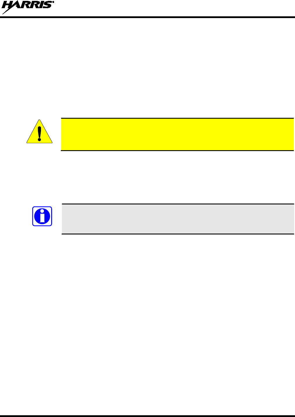
WARNING
The WARNING symbol calls attention to a procedure, practice, or the like, which,
if not correctly performed or adhered to, could result in personal injury. Do not
proceed beyond a WARNING symbol unti
l the conditions identified are fully
understood or met.
CAUTION
The CAUTION symbol calls attention to an operating procedure, practice, or the like,
which, if not performed correctly or adhered to, could result in damage to the
equipment or severely degrade equipment performance.
NOTE
The NOTE symbol calls attention to supplemental information, which may improve
system performance or clarify a process or procedure.
1.2 RF ENERGY EXPOSURE AWARENESS AND CONTROL
INFORMATION FOR FCC OCCUPATIONAL USE REQUIREMENTS
Before using the two-way mobile radio, review the following important RF energy awareness and
control information and operational instructions. Comply with this information and instructions in
order to ensure compliance with RF exposure guidelines.
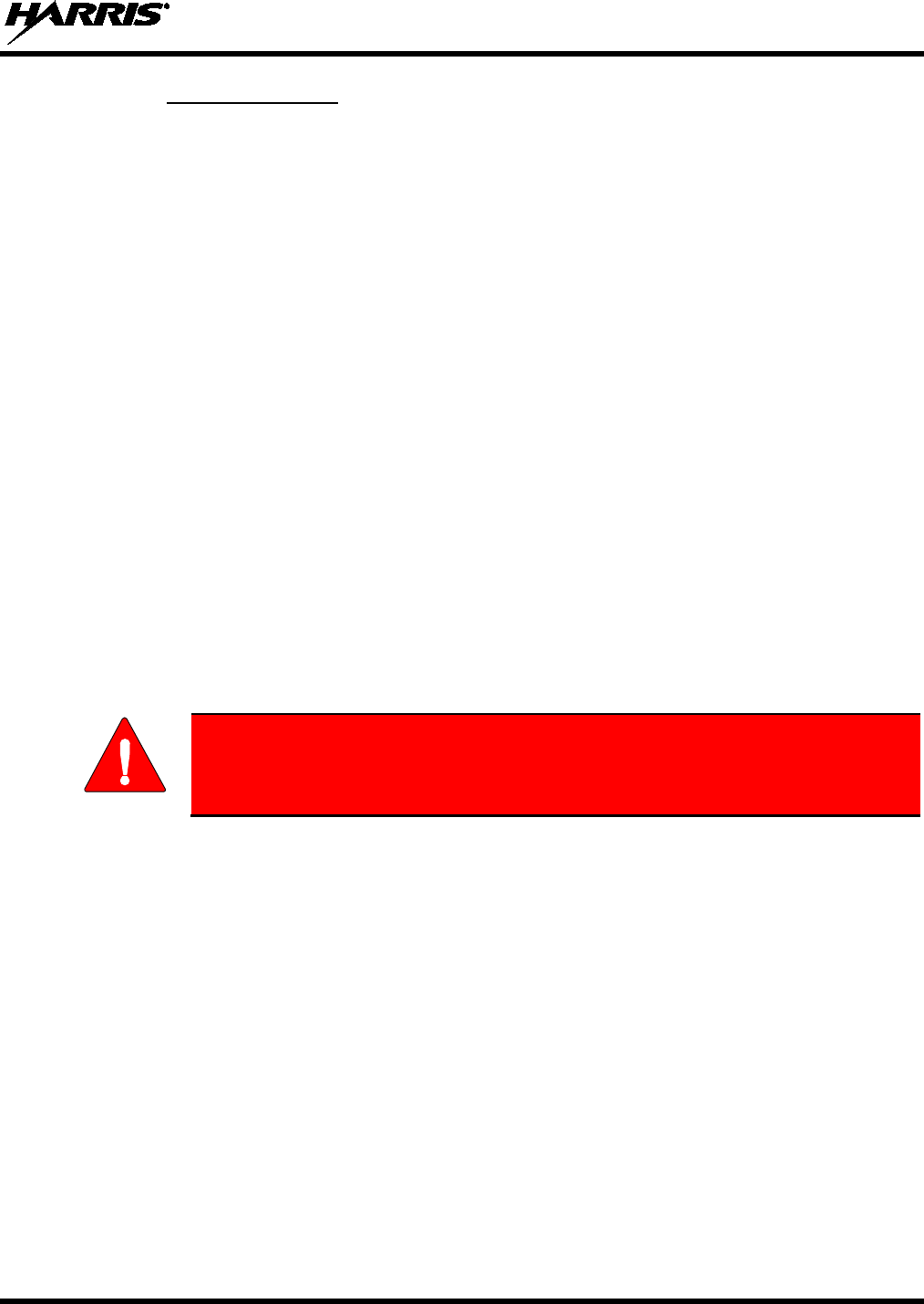
This radio is intended for use in occupational/controlled conditions, where users
have full knowledge of their exposure and can exercise control over their
exposure to remain below RF exposure limits. This radio is NOT authorized for
general population, consumer, or any other use.
Changes or modifications not expressly approved by Harris
could void the user's
authority to operate the equipment.
This two-way radio uses electromagnetic energy in the radio frequency (RF) spectrum to provide
communications between two or more users over a distance. It uses RF energy or radio waves to send and
receive calls. RF energy is one form of electromagnetic energy. Other forms include, but are not limited
to, electric power, sunlight, and x-rays. RF energy, however, should not be confused with these other
forms of electromagnetic energy, which, when used improperly, can cause biological damage. Very high
levels of x-rays, for example, can damage tissues and genetic material.
Experts in science, engineering, medicine, health, and industry work with organizations to develop
standards for exposure to RF energy. These standards provide recommended levels of RF exposure for
both workers and the general public. These recommended RF exposure levels include substantial margins
of protection. All two-way radios marketed in North America are designed, manufactured, and tested to
WARNING
CAUTION
14221-1510-4000, Rev. C
6
ensure they meet government-established RF exposure levels. In addition, manufacturers also recommend
specific operating instructions to users of two-way radios. These instructions are important because they
inform users about RF energy exposure and provide simple procedures on how to control it. Refer to the
following websites for more information on what RF energy exposure is and how to control exposure to
assure compliance with established RF exposure limits:
http://www.fcc.gov/oet/rfsafety/rf-faqs.html
http://www.osha.gov./SLTC/radiofrequencyradiation/index.html
1.2.1 Federal Communications Commission Regulations
Before it was marketed in the United States, the XG-25M two-way mobile radio was tested to ensure
compliance with FCC RF energy exposure limits for two-way mobile radios. When two-way radios are
used as a consequence of employment, the FCC requires users to be fully aware of and able to control
their exposure to meet occupational requirements. Exposure awareness can be facilitated by the use of a
label directing users to specific user awareness information. The radio has an RF exposure product label.
Also, this Product Safety Manual and the applicable Operator’s Manual include information and operating
instructions required to control RF exposure and to satisfy compliance requirements.
1.3 COMPLIANCE WITH RF EXPOSURE STANDARDS
The XG-25M two-way mobile radio is designed and tested to comply with a number of national and
international standards and guidelines regarding human exposure to RF electromagnetic energy. This
radio complies with the IEEE and ICNIRP exposure limits for occupational/controlled RF exposure
environment at duty-cycle times of up to 50% (50% transmit, 50% receive), and it is authorized by the
FCC for occupational use. In terms of measuring RF energy for compliance with the FCC exposure
guidelines, the radio’s antenna radiates measurable RF energy only while it is transmitting (talking), not
when it is receiving (listening), or in a standby mode.
The XG-25M two-way mobile radio complies with the following RF energy exposure standards and
guidelines:
• United States Federal Communications Commission (FCC), Code of Federal Regulations; 47 CFR
§ 2 sub-part J.
• American National Standards Institute (ANSI)/Institute of Electrical and Electronic Engineers (IEEE)
C95.1-2005.
• Institute of Electrical and Electronic Engineers (IEEE) C95.1-2005.
• IC Standard RSS-102, Issue 2, 2005: Spectrum Management and Telecommunications Radio
Standards Specification. Radiofrequency Exposure Compliance of Radiocommunication Apparatus
(All Frequency Bands).
Table 1-1 (for a VHF radio), Table 1-2 (for a UHF radio), and Table 1-3 (for a
700/800 MHz radio) list the recommended minimum safe lateral distances
for a
controlled environment and for unaware bystanders in an uncontrolled environment.
Distances in these three (3) tables are relative to transmitting antennas (i.e., monopoles
over a ground plane, or dipoles) at rated radio power for mobile radios installed in a
vehicle. Transmit only when unaware bystanders are at least the uncontrolled
recommended minimum safe lateral distance away from the transmitting antenna.
Based on the highest radiated RF power and the highest antenna gain in antennas to be used with
XG-25M, the distances listed in Table 1-1 (for the VHF radio), Table 1-2 (for UHF radio), and Table 1-3
(for the 700/800 MHz radio) are considered safe distances for controlled and uncontrolled environments
with the XG-25M mobile radio transmitting at a maximum 50% duty cycle:
CAUTION

14221-1510-4000, Rev. C
7
Table 1-1: Recommended Minimum Safe Lateral Distance from Transmitting Antenna
Connected to a VHF (136 to 174 MHz) XG-25M Mobile Radio
ANTENNA
ELEMENT PART
NUMBER ANTENNA DESCRIPTION
RECOMMENDED MINIMUM LATERAL HUMAN BODY
DISTANCE FROM TRANSMITTING ANTENNA
CONTROLLED
ENVIRONMENT
UNCONTROLLED
ENVIRONMENT
AN-225002-001 136 to 174 MHz, 0 dBd Gain 24.8 Inches
(63 Centimeters)
55.1 Inches
(140 Centimeters)
AN-225006-001 132 to 960 MHz, 0 dBd Gain
AN-225002-003 136 to 174 MHz, 3 dBd Gain 35.0 Inches
(89 Centimeters)
78.0 Inches
(198 Centimeters)
AN-225002-004 136 to 174 MHz, 2.4 dBd Gain 32.7 Inches
(83 Centimeters)
72.8 Inches
(185 Centimeters)
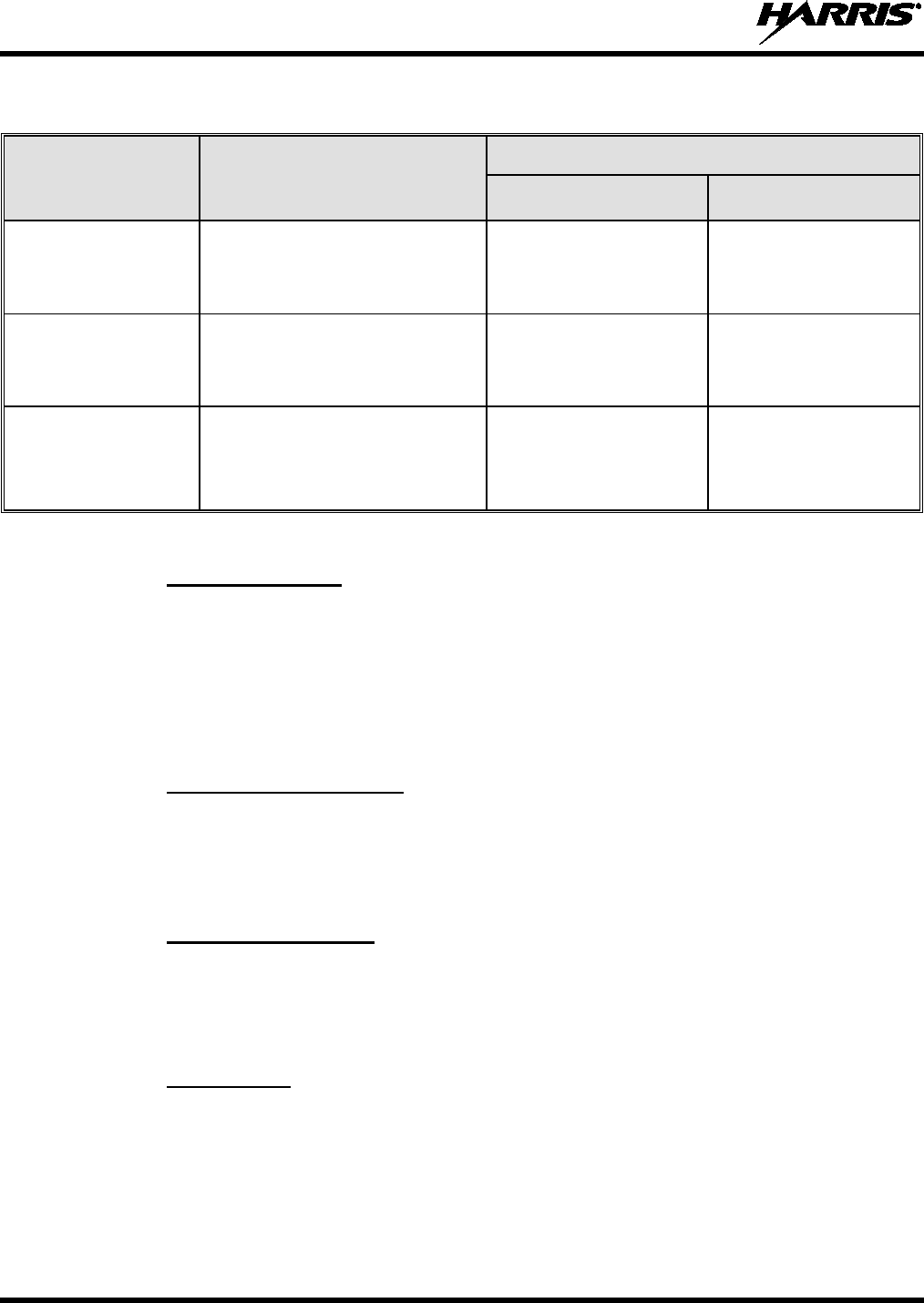
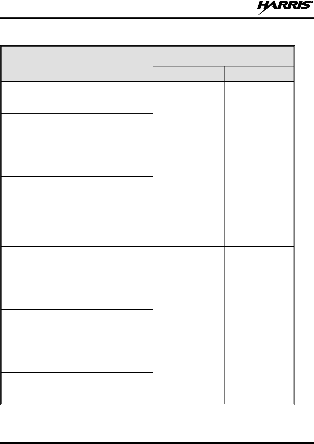
Table 1-2: Recommended Minimum Safe Lateral Distance from a Transmitting Antenna
Connected to a UHF (378 to 470 MHz) XG-25M Mobile Radio
ANTENNA
PART NUMBER ANTENNA DESCRIPTION
RECOMMENDED MINIMUM LATERAL HUMAN BODY
DISTANCE FROM TRANSMITTING ANTENNA
CONTROLLED
ENVIRONMENT
UNCONTROLLED
ENVIRONMENT
AN-125001-001
(mount) with
AN-225006-001
(element)
132 to 960 MHz;
Standard Rooftop-Mount;
0 dBd Gain; ¼-Wavelength; Field-
Tuned
21.3 Inches
(54 Centimeters)
47.2 Inches
(120 Centimeters)
AN-125001-001
(mount) with
AN-225003-001
(element)
378 to 430 MHz;
Standard Rooftop-Mount;
0 dBd Gain
AN-125001-001
(mount) with
AN-225003-004
(element)
378 to 430 MHz;
Standard Rooftop-Mount;
0 dBd Gain; Low-Profile
AN-125001-001
(mount) with
AN-225003-005
(element)
378 to 430 MHz;
Standard Rooftop-Mount;
2 dBd Gain; Low-Profile; NGP
28.0 Inches
(71 Centimeters)
61.8 Inches
(157 Centimeters)
AN-125001-001
(mount) with
AN-225004-001
(element)
450 to 512 MHz;
Standard Rooftop-Mount;
0 dBd Gain 20.1 Inches
(51 Centimeters)
44.9 Inches
(114 Centimeters)
AN-125001-001
(mount) with
AN-225004-004
(element)
450 to 512 MHz;
Standard Rooftop-Mount;
0 dBd Gain; Low-Profile
AN-125001-001
(mount) with
AN-225004-005
(element)
450 to 512 MHz;
Standard Rooftop-Mount;
2 dBd Gain; Low-Profile; NGP
25.6 Inches
(65 Centimeters)
56.7 Inches
(144 Centimeters)
(Table Continued on Next Page)

14221-1510-4000, Rev. C
8
Table 1-2: Recommended Minimum Safe Lateral Distance from a Transmitting Antenna
Connected to a UHF (378 to 470 MHz) XG-25M Mobile Radio
ANTENNA
PART NUMBER ANTENNA DESCRIPTION
RECOMMENDED MINIMUM LATERAL HUMAN BODY
DISTANCE FROM TRANSMITTING ANTENNA
CONTROLLED
ENVIRONMENT
UNCONTROLLED
ENVIRONMENT
AN-125001-003
(mount) with
AN-225006-001
(element)
132 to 960 MHz;
Thick Rooftop-Mount;
0 dBd Gain; ¼-Wavelength; Field-
Tuned
21.3 Inches
(54 Centimeters)
47.2 Inches
(120 Centimeters)
AN-125001-003
(mount) with
AN-225003-001
(element)
378 to 430 MHz;
Thick Rooftop-Mount;
0 dBd Gain
AN-125001-003
(mount) with
AN-225003-004
(element)
378 to 430 MHz;
Thick Rooftop-Mount;
0 dBd Gain; Low-Profile
AN-125001-003
(mount) with
AN-225003-005
(element)
378 to 430 MHz;
Thick Rooftop-Mount;
2 dBd Gain; Low-Profile; NGP
28.0 Inches
(71 Centimeters)
61.8 Inches
(157 Centimeters)
AN-125001-003
(mount) with
AN-225004-001
(element)
450 to 512 MHz;
Thick Rooftop-Mount;
0 dBd Gain 20.1 Inches
(51 Centimeters)
44.9 Inches
(114 Centimeters)
AN-125001-003
(mount) with
AN-225004-004
(element)
450 to 512 MHz;
Thick Rooftop-Mount;
0 dBd Gain; Low-Profile
AN-125001-003
(mount) with
AN-225004-005
(element)
450 to 512 MHz;
Thick Rooftop-Mount;
2 dBd Gain; Low-Profile; NGP
25.6 Inches
(65 Centimeters)
56.7 Inches
(144 Centimeters)
AN-125001-005
(mount) with
AN-225006-001
(element)
132 to 960 MHz; GPS Combo
Standard Rooftop-Mount;
0 dBd Gain; ¼-Wavelength; Field-
Tuned
21.3 Inches
(54 Centimeters)
47.2 Inches
(120 Centimeters)
AN-125001-005
(mount) with
AN-225003-001
(element)
378 to 430 MHz; GPS Combo
Standard Rooftop-Mount;
0 dBd Gain
AN-125001-005
(mount) with
AN-225003-004
(element)
378 to 430 MHz; GPS Combo
Standard Rooftop-Mount;
0 dBd Gain; Low-Profile
AN-125001-005
(mount) with
AN-225003-005
(element)
378 to 430 MHz; GPS Combo
Standard Rooftop-Mount;
2 dBd Gain; Low-Profile; NGP
28.0 Inches
(71 Centimeters)
61.8 Inches
(157 Centimeters)
(Table Continued on Next Page)

14221-1510-4000, Rev. C
9
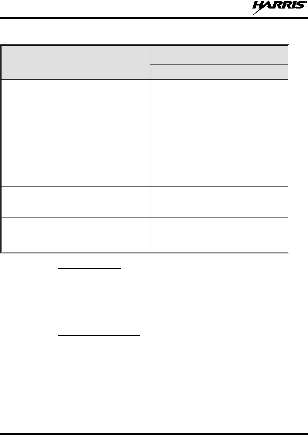
Table 1-2: Recommended Minimum Safe Lateral Distance from a Transmitting Antenna
Connected to a UHF (378 to 470 MHz) XG-25M Mobile Radio
ANTENNA
PART NUMBER ANTENNA DESCRIPTION
RECOMMENDED MINIMUM LATERAL HUMAN BODY
DISTANCE FROM TRANSMITTING ANTENNA
CONTROLLED
ENVIRONMENT
UNCONTROLLED
ENVIRONMENT
AN-125001-005
(mount) with
AN-225004-001
(element)
450 to 512 MHz; GPS Combo
Standard Rooftop-Mount;
0 dBd Gain 20.1 Inches
(51 Centimeters)
44.9 Inches
(114 Centimeters)
AN-125001-005
(mount) with
AN-225004-004
(element)
450 to 512 MHz; GPS Combo
Standard Rooftop-Mount;
0 dBd Gain; Low-Profile
AN-125001-005
(mount) with
AN-225004-005
(element)
450 to 512 MHz; GPS Combo
Standard Rooftop-Mount;
2 dBd Gain; Low-Profile; NGP
25.6 Inches
(65 Centimeters)
56.7 Inches
(144 Centimeters)
AN-125001-007
(mount) with
AN-225006-001
(element)
132 to 960 MHz; Magnetic-Mount;
0 dBd Gain; ¼-Wavelength; Field-
Tuned
21.3 Inches
(54 Centimeters)
47.2 Inches
(120 Centimeters)
AN-125001-007
(mount) with
AN-225003-001
(element)
378 to 430 MHz;
Magnetic-Mount;
0 dBd Gain
AN-125001-007
(mount) with
AN-225003-004
(element)
378 to 430 MHz;
Magnetic-Mount;
0 dBd Gain; Low-Profile
AN-125001-007
(mount) with
AN-225003-005
(element)
378 to 430 MHz;
Magnetic-Mount;
2 dBd Gain; Low-Profile; NGP
28.0 Inches
(71 Centimeters)
61.8 Inches
(157 Centimeters)
AN-125001-007
(mount) with
AN-225004-001
(element)
450 to 512 MHz;
Magnetic-Mount;
0 dBd Gain 20.1 Inches
(51 Centimeters)
44.9 Inches
(114 Centimeters)
AN-125001-007
(mount) with
AN-225004-004
(element)
450 to 512 MHz;
Magnetic-Mount;
0 dBd Gain; Low-Profile
AN-125001-007
(mount) with
AN-225004-005
(element)
450 to 512 MHz;
Magnetic-Mount;
2 dBd Gain; Low-Profile; NGP
25.6 Inches
(65 Centimeters)
56.7 Inches
(144 Centimeters)
AN102800V1
(Discontinued)
136 to 941 MHz; ¼-Wavelength*,
Standard Rooftop-Mount;
0 dBd Gain
21.3 Inches
(54 Centimeters)
47.2 Inches
(120 Centimeters)

14221-1510-4000, Rev. C
10
Table 1-3: Recommended Minimum Safe Lateral Distance from a Transmitting Antenna
Connected to a 700/800 MHz XG-25M Mobile Radio
ANTENNA
PART NUMBER ANTENNA DESCRIPTION
RECOMMENDED MINIMUM LATERAL HUMAN BODY
DISTANCE FROM TRANSMITTING ANTENNA
CONTROLLED
ENVIRONMENT
UNCONTROLLED
ENVIRONMENT
AN-125001-002
(mount) with
AN-225001-001
(element)
700/800 MHz
Standard Rooftop-Mount;
3 dBd Gain
9.8 Inches
(25 Centimeters)
21.7 Inches
(55 Centimeters)
AN-125001-002
(mount) with
AN-225001-002
(element)
700/800 MHz
Standard Rooftop-Mount;
Elevated-Feed 3 dBd Gain
AN-125001-002
(mount) with
AN-225001-003
(element)
700/800 MHz
Standard Rooftop-Mount;
Elevated-Feed, No Ground Plane
3 dBd Gain
AN-125001-002
(mount) with
AN-225001-004
(element)
700/800 MHz
Standard Rooftop-Mount;
Low-Profile 2 dBd Gain
AN-125001-002
(mount) with
AN-225006-001
(element)
132 to 960 MHz, ¼-Wavelength;
Standard Rooftop-Mount;
0 dBd Gain; Field-Tuned
AN-125001-002
(mount) with
AN-225001-005
(element)
700/800 MHz
Standard Rooftop-Mount;
5 dBd Gain
12.6 Inches
(32 Centimeters)
28.3 Inches
(72 Centimeters)
AN-125001-004
(mount) with
AN-225001-001
(element)
700/800 MHz
Thick Rooftop-Mount;
3 dBd Gain
9.8 Inches
(25 Centimeters)
21.7 Inches
(55 Centimeters)
AN-125001-004
(mount) with
AN-225001-002
(element)
700/800 MHz
Thick Rooftop-Mount;
Elevated-Feed 3 dBd Gain
AN-125001-004
(mount) with
AN-225001-003
(element)
700/800 MHz
Thick Rooftop-Mount;
Elevated-Feed, No Ground Plane
3 dBd Gain
AN-125001-004
(mount) with
AN-225001-004
(element)
700/800 MHz
Thick Rooftop-Mount;
Low-Profile 2 dBd Gain
AN-125001-004
(mount) with
AN-225006-001
(element)
132 to 960 MHz, ¼-Wavelength;
Thick Rooftop-Mount;
0 dBd Gain; Field-Tuned
(Table Continued on Next Page)

14221-1510-4000, Rev. C
11
Table 1-3: Recommended Minimum Safe Lateral Distance from a Transmitting Antenna
Connected to a 700/800 MHz XG-25M Mobile Radio
ANTENNA
PART NUMBER ANTENNA DESCRIPTION
RECOMMENDED MINIMUM LATERAL HUMAN BODY
DISTANCE FROM TRANSMITTING ANTENNA
CONTROLLED
ENVIRONMENT
UNCONTROLLED
ENVIRONMENT
AN-125001-004
(mount) with
AN-225001-005
(element)
700/800 MHz
Thick Rooftop-Mount;
5 dBd Gain
12.6 Inches
(32 Centimeters)
28.3 Inches
(72 Centimeters)
AN-125001-006
(mount) with
AN-225001-001
(element)
700/800 MHz GPS Combo
Rooftop-Mount;
3 dBd / 5.15 dBi Gain
9.8 Inches
(25 Centimeters)
21.7 Inches
(55 Centimeters)
AN-125001-006
(mount) with
AN-225001-002
(element)
700/800 MHz GPS Combo
Rooftop-Mount;
Elevated-Feed 3 dBd Gain
AN-125001-006
(mount) with
AN-225001-003
(element)
700/800 MHz GPS Combo
Rooftop-Mount;
Elevated-Feed, No Ground Plane
3 dBd Gain
AN-125001-006
(mount) with
AN-225001-004
(element)
700/800 MHz GPS Combo
Rooftop-Mount;
Low-Profile 2 dBd Gain
AN-125001-006
(mount) with
AN-225006-001
(element)
132 to 960 MHz, ¼-Wavelength;
Combo Rooftop-Mount;
0 dBd Gain; Field-Tuned
AN-125001-006
(mount) with
AN-225001-005
(element)
700/800 MHz GPS Combo
Rooftop-Mount;
5 dBd / 7.15 dBi Gain
12.6 Inches
(32 Centimeters)
28.3 Inches
(72 Centimeters)
AN-125001-008
(mount) with
AN-225001-001
(element)
700/800 MHz
Magnetic-Mount;
3 dBd Gain
9.8 Inches
(25 Centimeters)
21.7 Inches
(55 Centimeters)
AN-125001-008
(mount) with
AN-225001-002
(element)
700/800 MHz
Magnetic-Mount;
Elevated-Feed 3 dBd Gain
AN-125001-008
(mount) with
AN-225001-003
(element)
700/800 MHz
Magnetic-Mount; Elevated-Feed,
No Ground Plane 3 dBd Gain
AN-125001-008
(mount) with
AN-225001-004
(element)
700/800 MHz
Magnetic-Mount;
Low-Profile 2 dBd Gain
(Table Continued on Next Page)
14221-1510-4000, Rev. C
12
Table 1-3: Recommended Minimum Safe Lateral Distance from a Transmitting Antenna
Connected to a 700/800 MHz XG-25M Mobile Radio
ANTENNA
PART NUMBER ANTENNA DESCRIPTION
RECOMMENDED MINIMUM LATERAL HUMAN BODY
DISTANCE FROM TRANSMITTING ANTENNA
CONTROLLED
ENVIRONMENT
UNCONTROLLED
ENVIRONMENT
AN-125001-008
(mount) with
AN-225006-001
(element)
132 to 960 MHz, ¼-Wavelength;
Magnetic-Mount Rooftop-Mount;
0 dBd Gain; Field-Tuned
9.8 Inches
(25 Centimeters)
21.7 Inches
(55 Centimeters)
AN-125001-008
(mount) with
AN-225001-005
(element)
700/800 MHz
Magnetic-Mount;
5 dBd Gain
12.6 Inches
(32 Centimeters)
28.3 Inches
(72 Centimeters)
AN102800V1
(Discontinued)
136 to 941 MHz, ¼-Wavelength*,
Standard Rooftop-Mount;
0 dBd Gain
9.8 Inches
(25 Centimeters)
21.7 Inches
(55 Centimeters)
1.3.1 Mobile Antennas
The antenna(s) for the radio must be installed in accordance with the antenna installation procedures
found in the Installation Manual. Refer to the RELATED PUBLICATIONS section on page 32 for the
respective publication number. Installation guidelines presented in the Installation Manual are limited to
metal-body motor vehicles or vehicles with appropriate ground planes.
Use only approved/supplied antenna(s) or an approved replacement antenna. Unauthorized antennas,
modifications, or attachments can cause the FCC RF exposure limits to be exceeded.
1.3.2 Approved Accessories
The radio has been tested and meets FCC RF guidelines when used with accessories supplied or
designated for use with it. Use of other accessories may not ensure compliance with the FCC’s RF
exposure guidelines, and may violate FCC regulations. For a list of approved accessories refer to the
Installation Manual and/or the Products and Services Catalog.
1.3.3 Contact Information
For additional information on RF exposure and other information, contact Harris using one of the contact
links listed in Section 6 on page 32.
1.4 RADIO FREQUENCY INTERFERENCE
1.4.1 FCC Part 15
This device complies with Part 15 of the FCC Rules. Operation is subject to the following two conditions:
1. This device may not cause harmful interference; and,
2. This device must accept any interference received, including interference that may cause undesired
operation.
14221-1510-4000, Rev. C
13
1.4.2 Industry Canada
This device complies with Industry Canada license-exempt RSS standard(s). Operation is subject to the
following two conditions: (1) this device may not cause interference, and (2) this device must accept any
interference, including interference that may cause undesired operation of the device.
1.5 OCCUPATIONAL SAFETY GUIDELINES AND SAFETY TRAINING
INFORMATION
To ensure bodily exposure to RF electromagnetic energy is within the FCC allowable limits for
occupational use. Always adhere to the following basic guidelines:
• The push-to-talk button should only be depressed when intending to send a voice message.
• The radio should only be used for necessary work-related communications.
• The radio should only be used by authorized and trained personnel. It should never be operated by
children.
• Do not attempt any unauthorized modification to the radio. Changes or modifications to the radio may
cause harmful interference and/or cause it to exceed FCC RF exposure limits. Only qualified
personnel should service the radio.
• Always use only authorized accessories (antennas, speakers/mics, etc.). Use of unauthorized
accessories can cause the FCC RF exposure compliance requirements to be exceeded.
The information listed above provides the user with information needed to make him or her aware of a RF
exposure, and what to do to assure that this radio operates within the FCC exposure limits of this radio.
1.6 COMMON HAZARDS
The operator of any mobile radio should be aware of certain hazards common to
the operation of vehicular radio transmissions. Possible hazards include but are
not limited to:
• Explosive Atmospheres — Just as it is dangerous to fuel a vehicle while its engine is running, be
sure to turn the radio OFF while fueling the vehicle. If the radio is mounted in the trunk of the
vehicle, DO NOT carry containers of fuel in the trunk.
Areas with potentially explosive atmosphere are often, but not always, clearly marked. Turn the radio
OFF when in any area with a potentially explosive atmosphere. It is rare, but not impossible that the
radio or its accessories could generate sparks.
• Interference To Vehicular Electronic Systems — Electronic fuel injection systems, electronic anti-
skid braking systems, electronic cruise control systems, etc., are typical of the types of electronic
devices that can malfunction due to the lack of protection from radio frequency (RF) energy present
when transmitting. If the vehicle contains such equipment, consult the dealer for the make of vehicle
and enlist his/her aid in determining if such electronic circuits perform normally when the radio is
transmitting.
• Electric Blasting Caps — To prevent accidental detonation of electric blasting caps, DO NOT use
two-way radios within 1000 feet (305 meters) of blasting operations. Always obey the “Turn Off
Two-Way Radios” (or equivalent) signs posted where electric blasting caps are being used. (OSHA
Standard: 1926.900).
WARNING

14221-1510-4000, Rev. C
14
• Radio Frequency Energy — To prevent burns or related physical injury from radio frequency
energy, do not operate the transmitter when anyone outside of the vehicle is within the minimum safe
distance from the antenna as specified in Table 1-1. Refer to Section 1.2 for additional information.
• Vehicles Powered By Liquefied Petroleum (LP) Gas — Radio installation in vehicles powered by
liquefied petroleum gas, where the LP gas container is located in the trunk or other sealed-off space
within the interior of the vehicle, must conform to the National Fire Protection Association standard
NFPA 58. This requires:
The space containing the radio equipment must be isolated by a seal from the space containing
the LP gas container and its fittings.
Outside filling connections must be used for the LP gas container.
The LP gas container space shall be vented to the outside of the vehicle.
• Vehicles Equipped with Airbags — For driver and passenger safety, avoid mounting the radio (or
any other component) above or near airbag deployment areas. In addition to driver-side and
passenger-side front-impact airbags, some vehicles may also be equipped with side-impact airbags.
For occupant safety, verify the location of all airbags within the vehicle before installing the radio
equipment.
1.7 SAFE DRIVING RECOMMENDATIONS
The American Automobile Association (AAA) advocates the following key safe driving recommenda-
tions:
• Read the literature on the safe operation of the radio.
• Keep both hands on the steering wheel and the microphone in its hanger whenever the vehicle is in
motion.
• Place calls only when the vehicle is stopped.
• When talking from a moving vehicle is unavoidable, drive in the slower lane. Keep conversations
brief.
• If a conversation requires taking notes or complex thought, stop the vehicle in a safe place and
continue the call.
• Whenever using a mobile radio, exercise caution.
1.8 OPERATING RULES AND REGULATIONS
Two-way radio systems must be operated in accordance with the rules and regulations of the local,
regional, or national government.
In the United States, the XG-25M mobile radio must be operated in accordance with the rules and
regulations of the Federal Communications Commission (FCC). Operators of two-way radio equipment
must be thoroughly familiar with the rules that apply to the particular type of radio operation. Following
these rules helps eliminate confusion, assures the most efficient use of the existing radio channels, and
results in a smoothly functioning radio network.
When using a two-way radio, remember these rules:
• It is a violation of FCC rules to interrupt any distress or emergency message. The radio operates in
much the same way as a telephone “party line.” Therefore, always listen to make sure the channel is
clear before transmitting. Emergency calls have priority over all other messages. If someone is
sending an emergency message – such as reporting a fire or asking for help in an accident, do not
transmit unless assistance can be offered.
• The use of profane or obscene language is prohibited by Federal law.
14221-1510-4000, Rev. C
15
• It is against the law to send false call letters or false distress or emergency messages. The FCC
requires keeping conversations brief and confined to business. Use coded messages whenever
possible to save time.
• Using the radio to send personal messages (except in an emergency) is a violation of FCC rules. Send
only essential messages.
• It is against Federal law to repeat or otherwise make known anything overheard on the radio.
Conversations between others sharing the channel must be regarded as confidential.
• The FCC requires self-identification at certain specific times by means of call letters. Refer to the
rules that apply to the particular type of operation for the proper procedure.
• No changes or adjustments shall be made to the equipment except by an authorized or certified
electronics technician.
Under U.S. law, operation of an unlicensed radio transmitter within the jurisdiction of
the United States may be punishable by a fine of up to $10,000, imprisonment for up to
two (2) years, or both.
1.9 OPERATING TIPS
The following conditions tend to reduce the effective range of two-way radios and should be avoided
whenever possible:
• Operating the radio in areas of low terrain, or while under power lines or bridges.
• Obstructions such as mountains and buildings.
In areas where transmission or reception is poor, communication improvement may
sometimes be obtained by moving a few yards in another direction, or moving to a
higher elevation.
CAUTION
NOTE
14221-1510-4000, Rev. C
16
2 RENSEIGNEMENTS SUR LA RÉGLEMENTATION ET
SÉCURITÉ
2.1 CONVENTIONS SUR LES SYMBOLES DE SÉCURITÉ
Les conventions suivantes sont utilisées dans le présent manuel pour avertir l’utilisateur des précautions
générales de sécurité qui doivent être observées pendant toutes les phases d’opération, d’entretien et de
réparation de ce produit. Le non-respect de ces précautions ou d’avertissements précisés ailleurs enfreint
les normes de sécurité de la conception, de la fabrication et de l’utilisation prévue du produit. Harris
n’assume aucune responsabilité pour le non-respect de ces normes par le client.
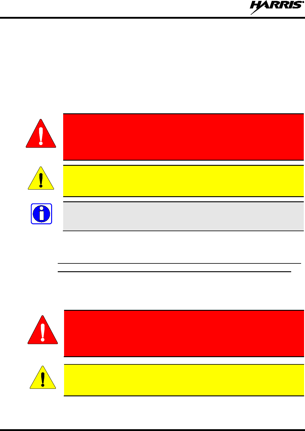
MISE EN GARDE
Le symbole MISE EN GARDE attire l’
attention sur une procédure ou une
pratique qui, si elle n’
est pas correctement effectuée ou observée, pourrait
entraîner une blessure personnelle. Ne pas poursuivre au-delà d’un symbole de
MISE
EN GARDE avant que les conditions identifiées soient complètement
comprises ou satisfaites.
AVERTISSEMENT
Le symbole AVERTISSEMENT attire l’attention sur une procédure ou une pratique
opérationnelle qui, si elle n’est pas correctement
effectuée ou observée, pourrait
entraîner un bris d’équipement ou une importante baisse de rendement de l’équipement.
REMARQUE
Le symbole REMARQUE attire l’attention sur des renseignements supplémentaires qui
peuvent améliorer le rendement du système ou clarifier un processus ou une procédure.
2.2 RENSEIGNEMENTS SUR UNE EXPOSITION À L’ÉNERGIE DES RF
2.2.1 Renseignements Sur Le Contrôle Et La Sensibilisation À L’énergie Des
RF Pour Les Exigences D’une Utilisation Professionnelle De La FCC
Avant d’utiliser les radios mobiles bidirectionnelles, passez en revue les renseignements et les
instructions opérationnelles importants suivants sur le contrôle et la sensibilisation à l’énergie des
RF. Se conformer à ces renseignements et instructions pour assurer la conformité aux directives
d’exposition aux RF.
MISE EN GARDE
Cette radio est destinée à être utilisée dans des conditions professionnelles/
contrôlées, où les utilisateurs ont une pleine connaissance de leur exposition et
peuv
ent exercer un contrôle sur leur exposition pour rester sous les limites
d’exposition aux RF. Cette radio N’est PAS autorisée pour la population générale,
les consommateurs ou toute autre utilisation.
AVERTISSEMENT
Des changements ou modifications non expressément approuvés par Harris pourraient
annuler le droit d’utilisation de l’équipement pour l’utilisateur.
Cette radio bidirectionnelle utilise une énergie électromagnétique dans le spectre des radiofréquences
(RF) pour permettre une communication à distance entre deux utilisateurs ou plus. Elle utilise l’énergie

14221-1510-4000, Rev. C
17
des RF ou les ondes radio pour envoyer et recevoir des appels. L’énergie des RF est une forme d’énergie
électromagnétique. D’autres formes comprennent, entre autres, l’énergie électrique, la lumière du soleil et
les rayons X. Toutefois, l’énergie des RF ne doit pas être confondue avec ces autres formes d’énergie
électromagnétique qui, lorsque mal utilisées, peuvent causer des dommages biologiques. Par exemple, des
niveaux très élevés de rayons X peuvent endommager les tissus et le matériel génétique.
Des experts en science, en ingénierie, en médecine, en santé et de l’industrie travaillent avec des
organismes pour établir des normes pour l’exposition à l’énergie des RF. Ces normes procurent des
niveaux recommandés d’exposition aux RF autant aux travailleurs qu’au grand public. Ces niveaux
d’exposition aux RF recommandés comprennent d’importantes marges de protection. Toutes les radios
bidirectionnelles commercialisées en Amérique du Nord sont conçues, fabriquées et testées pour s’assurer
qu’elles satisfont les niveaux d’exposition aux RF établis par le gouvernement. Les fabricants
recommandent également des consignes d’utilisation particulières aux utilisateurs de radios
bidirectionnelles. Ces instructions sont importantes, car elles informent les utilisateurs sur l’exposition à
l’énergie des RF et donnent des procédures simples sur la manière de contrôler cette exposition.
Consultez les sites Web suivants (en anglais) pour de plus amples renseignements sur ce qu’est
l’exposition à l’énergie des RF et comment contrôler l’exposition pour assurer la conformité aux limites
d’exposition établies :
http://www.fcc.gov/oet/rfsafety/rf-faqs.html
http://www.osha.gov./SLTC/radiofrequencyradiation/index.html
2.2.1.1 Règlements de la Federal Communications Commission (« Commission
fédérale des communications » aux États-Unis)
Avant d’être mise sur le marché aux États-Unis, la radio mobile bidirectionnelle XG-25M a été testée
pour s’assurer de sa conformité aux limites d’exposition à l’énergie des RF de la FCC pour les radios
mobiles bidirectionnelles. Lorsque les radios bidirectionnelles sont utilisées à la suite d’une embauche, la
FCC demande aux utilisateurs de bien connaître et de pouvoir contrôler leur exposition pour satisfaire les
exigences professionnelles. La sensibilisation à l’exposition peut être facilitée par l’utilisation d’une
étiquette qui dirige les utilisateurs vers des renseignements particuliers sur la sensibilisation de
l’utilisateur. La radio possède une étiquette de produit sur l’exposition aux RF. De plus, le Manuel sur la
sécurité du produit et le présent Manuel de l’opérateur comprennent des renseignements et les consignes
d’utilisation nécessaires pour contrôler l’exposition aux RF et pour satisfaire les exigences de conformité.
2.3 CONFORMITÉ AUX NORMES D’EXPOSITION AUX RF
La radio mobile bidirectionnelle XG-25M est conçue et testée pour être conforme à un certain nombre de
normes et directives nationales et internationales quant à l’exposition humaine à l’énergie
électromagnétique des RF. Cette radio est conforme aux limites d’exposition de l’IEEE et de la
Commission internationale de protection contre les rayonnements non ionisants pour un environnement
professionnel/contrôlé d’exposition aux RF à des périodes de cycle de service allant jusqu’à 50 % (50 %
de transmission, 50 % de réception) et elle est autorisée par la FCC pour une utilisation professionnelle.
Sur le plan de la mesure de l’énergie des RF pour la conformité aux directives d’exposition de la FCC,
l’antenne de la radio irradie une énergie des RF mesurable seulement lorsqu’elle transmet (parler), et non
lorsqu’elle reçoit (écouter) ou en mode d’attente.
La radio mobile bidirectionnelle XG-25M est conforme aux normes et directives d’exposition à l’énergie
des RF suivantes :
• Federal Communications Commission (FCC) américaine, le Code of Federal Regulations; 47 CFR
§ 2 sous-partie J.
• American National Standards Institute (ANSI)/Institute of Electrical and Electronic Engineers (IEEE)
C95.1-2005.
14221-1510-4000, Rev. C
18
• Institute of Electrical and Electronic Engineers (IEEE) C95.1-2005.
• IC Standard RSS-102, numéro 2, 2005 : Spectrum Management and Telecommunications Radio
Standards Specification. Radiofrequency Exposure Compliance of Radiocommunication Apparatus
(All Frequency Bands).
AVERTISSEMENT
Tableau 2-1, Tableau 2-2 et Tableau 2-3 indiquent les distances latérales sécuritaires
minimales recommandées pour un environnement contrôlé et pour les spectateurs
ignorants dans un environnement non contrôlé, d’antennes de transmission (c.-à-d., des
monopôles sur un plan de sol, ou des dipôles) à une puissance de radio évaluée pour les
radios mobiles installées dans un véhicule. Ils ne transmettent que lorsque les
spectateurs ignorants sont au moins à la distance latérale sécuritaire minimale
recommandée non contrôlée de l’antenne de transmission.
Basées sur la puissance des RF irradiées la plus élevée et le gain d’antenne le plus élevé dans les antennes
à utiliser avec le XG-25M, les distances indiquées dans les Tableau 2-1 (pour la radio à 136 à 174 MHz),
Tableau 2-2 (pour la radio à 378 à 470 MHz) et Tableau 2-3 (pour la radio à 700/800 MHz) sont
considérées comme des distances sécuritaires pour des environnements contrôlés et non contrôlés avec la
radio mobile XG-25M qui transmet à un cycle de service maximal de 50 % :
Tableau 2-1 : Distance latérale sécuritaire minimale recommandée d’une antenne de transmission
branchée sur une radio mobile XG-25M de 136 à 174 MHz
NUMÉRO DE
PIÈCE DE
L’ÉLÉMENT DE
L’ANTENNE
DESCRIPTION DE
L’ANTENNE
DISTANCE MINIMALE RECOMMANDÉE DE
L’ANTENNE DE TRANSMISSION POUR LE CORPS
HUMAIN
ENVIRONNEMENT
CONTRÔLÉ
ENVIRONNEMENT
NON CONTRÔLÉ
AN-225002-001 136 à 174 MHz, gain de 0 dBd 63 cm
(24,8 po)
140 cm
(55,1 po)
AN-225006-001 132 à 960 MHz, gain de 0 dBd
AN-225002-003 136 à 174 MHz, gain de 3 dBd 89 cm
(35,0 po)
198 cm
(78,0 po)
AN-225002-004 136 à 174 MHz, gain de 2,4 dBd 83 cm
(32,7 po)
185 cm
(72,8 po)

14221-1510-4000, Rev. C
19
Tableau 2-2: Distance latérale sécuritaire minimale recommandée d’une antenne de transmission
branchée sur une radio mobile XG-25M de 378 à 470 MHz (UHF)
NUMÉRO DE
PIÈCE DE
L’ANTENNE
DESCRIPTION DE
L’ANTENNE
DISTANCE MINIMALE RECOMMANDÉE DE
L’ANTENNE DE TRANSMISSION POUR LE CORPS
HUMAIN
ENVIRONNEMENT
CONTRÔLÉ
ENVIRONNEMENT
NON CONTRÔLÉ
AN-125001-001
(monture) avec
AN-225006-001
(élément)
132 à 960 MHz; antenne de toit
standard; gain de 0 dBd;
¼ - longueur d’onde; syntonisé
sur place
54 cm
(21.3 po)
120 cm
(47.2 po)
AN-125001-001
(monture) avec
AN-225003-001
(élément)
378 à 430 MHz; antenne de toit
standard; gain de 0 dBd
AN-125001-001
(monture) avec
AN-225003-004
(élément)
378 à 430 MHz; antenne de toit
standard; gain de 0 dBd; profil
bas
AN-125001-001
(monture) avec
AN-225003-005
(élément)
378 à 430 MHz; antenne de toit
standard; gain de 2 dBd; profil
bas; sans plan de sol
71 cm
(28.0 po)
157 cm
(61.8 po)
AN-125001-001
(monture) avec
AN-225004-001
(élément)
450 à 512 MHz; antenne de toit
standard; gain de 0 dBd
51 cm
(20.1 po)
114 cm
(44.9 po)
AN-125001-001
(monture) avec
AN-225004-004
(élément)
450 à 512 MHz; antenne de toit
standard; gain de 0 dBd; profil
bas
AN-125001-001
(monture) avec
AN-225004-005
(élément)
450 à 512 MHz; antenne de toit
standard; gain de 2 dBd; profil
bas; sans plan de sol
65 cm
(25.6 po)
144 cm
(56.7 po)
AN-125001-003
(monture) avec
AN-225006-001
(élément)
132 à 960 MHz; antenne de toit
épais de; gain de 0 dBd;
¼ - longueur d’onde; syntonisé
sur place
54 cm
(21.3 po)
120 cm
(47.2 po)
AN-125001-003
(monture) avec
AN-225003-001
(élément)
378 à 430 MHz; antenne de toit
épais de; gain de 0 dBd
AN-125001-003
(monture) avec
AN-225003-004
(élément)
378 à 430 MHz; antenne de toit
épais de; gain de 0 dBd; profil bas
(Suite du tableau à la page suivante)

14221-1510-4000, Rev. C
20
Tableau 2-2: Distance latérale sécuritaire minimale recommandée d’une antenne de transmission
branchée sur une radio mobile XG-25M de 378 à 470 MHz (UHF)
NUMÉRO DE
PIÈCE DE
L’ANTENNE
DESCRIPTION DE
L’ANTENNE
DISTANCE MINIMALE RECOMMANDÉE DE
L’ANTENNE DE TRANSMISSION POUR LE CORPS
HUMAIN
ENVIRONNEMENT
CONTRÔLÉ
ENVIRONNEMENT
NON CONTRÔLÉ
AN-125001-003
(monture) avec
AN-225003-005
(élément)
378 à 430 MHz; antenne de toit
épais de; gain de 2 dBd; profil
bas; sans plan de sol
71 cm
(28.0 po)
157 cm
(61.8 po)
AN-125001-003
(monture) avec
AN-225004-001
(élément)
450 à 512 MHz; antenne de toit
épais de; gain de 0 dBd
51 cm
(20.1 po)
114 cm
(44.9 po)
AN-125001-003
(monture) avec
AN-225004-004
(élément)
450 à 512 MHz; antenne de toit
épais de; gain de 0 dBd; profil bas
AN-125001-003
(monture) avec
AN-225004-005
(élément)
450 à 512 MHz; antenne de toit
épais de; gain de 2 dBd; profil
bas; sans plan de sol
65 cm
(25.6 po)
144 cm
(56.7 po)
AN-125001-005
(monture) avec
AN-225006-001
(élément)
132 à 960 MHz; Combo antenne
de toit épais et; gain de 0 dBd;
¼ - longueur d’onde; syntonisé
sur place
54 cm
(21.3 po)
120 cm
(47.2 po)
AN-125001-005
(monture) avec
AN-225003-001
(élément)
378 à 430 MHz; Combo antenne
de toit épais et; gain de 0 dBd
AN-125001-005
(monture) avec
AN-225003-004
(élément)
378 à 430 MHz; Combo antenne
de toit épais et; gain de 0 dBd;
profil bas
AN-125001-005
(monture) avec
AN-225003-005
(élément)
378 à 430 MHz; Combo antenne
de toit épais et; gain de 2 dBd;
profil bas; sans plan de sol
71 cm
(28.0 po)
157 cm
(61.8 po)
AN-125001-005
(monture) avec
AN-225004-001
(élément)
450 à 512 MHz; Combo antenne
de toit épais et; gain de 0 dBd
51 cm
(20.1 po)
114 cm
(44.9 po)
AN-125001-005
(monture) avec
AN-225004-004
(élément)
450 à 512 MHz; Combo antenne
de toit épais et; gain de 0 dBd;
profil bas
(Suite du tableau à la page suivante)

14221-1510-4000, Rev. C
21
Tableau 2-2: Distance latérale sécuritaire minimale recommandée d’une antenne de transmission
branchée sur une radio mobile XG-25M de 378 à 470 MHz (UHF)
NUMÉRO DE
PIÈCE DE
L’ANTENNE
DESCRIPTION DE
L’ANTENNE
DISTANCE MINIMALE RECOMMANDÉE DE
L’ANTENNE DE TRANSMISSION POUR LE CORPS
HUMAIN
ENVIRONNEMENT
CONTRÔLÉ
ENVIRONNEMENT
NON CONTRÔLÉ
AN-125001-005
(monture) avec
AN-225004-005
(élément)
450 à 512 MHz; Combo antenne
de toit épais et; gain de 2 dBd;
profil bas; sans plan de sol
65 cm
(25.6 po)
144 cm
(56.7 po)
AN-125001-007
(monture) avec
AN-225006-001
(élément)
132 à 960 MHz; montage
magnétique; gain de 0 dBd;
¼ - longueur d’onde; syntonisé
sur place
54 cm
(21.3 po)
120 cm
(47.2 po)
AN-125001-007
(monture) avec
AN-225003-001
(élément)
378 à 430 MHz; montage
magnétique; gain de 0 dBd
AN-125001-007
(monture) avec
AN-225003-004
(élément)
378 à 430 MHz; montage
magnétique; gain de 0 dBd; profil
bas
AN-125001-007
(monture) avec
AN-225003-005
(élément)
378 à 430 MHz; montage
magnétique; gain de 2 dBd; profil
bas; sans plan de sol
71 cm
(28.0 po)
157 cm
(61.8 po)
AN-125001-007
(monture) avec
AN-225004-001
(élément)
450 à 512 MHz; montage
magnétique; gain de 0 dBd
51 cm
(20.1 po)
114 cm
(44.9 po)
AN-125001-007
(monture) avec
AN-225004-004
(élément)
450 à 512 MHz; montage
magnétique; gain de 0 dBd; profil
bas
AN-125001-007
(monture) avec
AN-225004-005
(élément)
450 à 512 MHz; montage
magnétique; gain de 2 dBd; profil
bas; sans plan de sol
65 cm
(25.6 po)
144 cm
(56.7 po)
AN102800V1
(n’est plus vendu)
136 à 941 MHz; ¼ - longueur
d’onde, antenne de toit standard;
gain de 0 dBd
54 cm
(21.3 po)
120 cm
(47.2 po)
14221-1510-4000, Rev. C
22
Tableau 2-3 : Distance latérale sécuritaire minimale recommandée d’une antenne de transmission
branchée sur une radio mobile XG-25M de 700/800 MHz
NUMÉRO DE
PIÈCE DE
L’ANTENNE
DESCRIPTION DE
L’ANTENNE
DISTANCE MINIMALE RECOMMANDÉE DE
L’ANTENNE DE TRANSMISSION POUR LE CORPS
HUMAIN
ENVIRONNEMENT
CONTRÔLÉ
ENVIRONNEMENT
NON CONTRÔLÉ
AN-125001-002
(monture) avec
AN-225001-001
(élément)
Antenne de toit standard de
700/800 MHz;
gain de 3 dBd
25 cm
(9,8 po)
55 cm
(21,7 po)
AN-125001-002
(monture) avec
AN-225001-002
(élément)
Antenne de toit standard de
700/800 MHz;
point d’alimentation surélevé,
gain de 3 dBd
AN-125001-002
(monture) avec
AN-225001-003
(élément)
Antenne de toit standard de
700/800 MHz;
point d’alimentation surélevé,
gain de 3 dBd sans plan de sol
AN-125001-002
(monture) avec
AN-225001-004
(élément)
Antenne de toit standard de
700/800 MHz;
gain de 2 dBd à profil bas
AN-125001-002
(monture) avec
AN-225006-001
(élément)
132 à 960 MHz,
¼ - longueur d’onde;
antenne de toit standard;
gain de 0 dBd;
syntonisé sur place
AN-125001-002
(monture) avec
AN-225001-005
(élément)
Antenne de toit standard de
700/800 MHz;
gain de 5 dBd
32 cm
(12,6 po)
72 cm
(28,3 po)
AN-125001-004
(monture) avec
AN-225001-001
(élément)
Antenne de toit épais de
700/800 MHz;
gain de 3 dBd
25 cm
(9,8 po)
155 cm
(21,7 po)
AN-125001-004
(monture) avec
AN-225001-002
(élément)
Antenne de toit épais de
700/800 MHz;
point d’alimentation surélevé,
gain de 3 dBd
AN-125001-004
(monture) avec
AN-225001-003
(élément)
Antenne de toit épais de
700/800 MHz;
point d’alimentation surélevé,
gain de 3 dBd sans plan de sol
AN-125001-004
(monture) avec
AN-225001-004
(élément)
Antenne de toit épais de
700/800 MHz;
gain de 2 dBd à profil bas
(Suite du tableau à la page suivante)

14221-1510-4000, Rev. C
23
Tableau 2-3 : Distance latérale sécuritaire minimale recommandée d’une antenne de transmission
branchée sur une radio mobile XG-25M de 700/800 MHz
NUMÉRO DE
PIÈCE DE
L’ANTENNE
DESCRIPTION DE
L’ANTENNE
DISTANCE MINIMALE RECOMMANDÉE DE
L’ANTENNE DE TRANSMISSION POUR LE CORPS
HUMAIN
ENVIRONNEMENT
CONTRÔLÉ
ENVIRONNEMENT
NON CONTRÔLÉ
AN-125001-004
(monture) avec
AN-225006-001
(élément)
132 à 960 MHz,
¼ - longueur d’onde;
pour toit épais;
gain de 0 dBd; syntonisé sur
place
25 cm
(9,8 po)
155 cm
(21,7 po)
AN-125001-004
(monture) avec
AN-225001-005
(élément)
Antenne de toit
épais de 700/800 MHz;
gain de 5 dBd
32 cm
(12,6 po)
72 cm
(28,3 po)
AN-125001-006
(monture) avec
AN-225001-001
(élément)
Combo antenne de toit et GPS
de 700/800 MHz;
gain de 3 dBd / 5,15 dBi
25 cm
(9,8 po)
55 cm
(21,7 po)
AN-125001-006
(monture) avec
AN-225001-002
(élément)
Combo antenne de toit épais et
GPS de 700/800 MHz;
point d’alimentation surélevé,
gain de 3 dBd
AN-125001-006
(monture) avec
AN-225001-003
(élément)
Combo antenne de toit et GPS
700/800 MHz;
point d’alimentation surélevé,
gain de 3 dBd sans plan de sol
AN-125001-006
(monture) avec
AN-225001-004
(élément)
Combo antenne de toit et GPS
de 700/800 MHz;
gain de 2 dBd à profil bas
AN-125001-006
(support) avec
AN-225006-001
(élément)
132 à 960 MHz,
¼ - longueur d’onde;
support sur le toit à combo;
gain de 0 dBd; champ
syntonisé
AN-125001-006
(monture) avec
AN-225001-005
(élément)
Combo antenne de toit et GPS
de 700/800 MHz;
gain de 5 dBd / 7,15 dBi
32 cm
(12,6 po)
72 cm
(28,3 po)
AN-125001-008
(monture) avec
AN-225001-001
(élément)
Antenne magnétique de
700/800 MHz;
gain de 3 dBd 25 cm
(9,8 po)
55 cm
(21,7 po)
AN-125001-008
(monture) avec
AN-225001-002
(élément)
Antenne magnétique de
700/800 MHz;
point d’alimentation surélevé,
gain de 3 dBd
(Suite du tableau à la page suivante)
14221-1510-4000, Rev. C
24
Tableau 2-3 : Distance latérale sécuritaire minimale recommandée d’une antenne de transmission
branchée sur une radio mobile XG-25M de 700/800 MHz
NUMÉRO DE
PIÈCE DE
L’ANTENNE
DESCRIPTION DE
L’ANTENNE
DISTANCE MINIMALE RECOMMANDÉE DE
L’ANTENNE DE TRANSMISSION POUR LE CORPS
HUMAIN
ENVIRONNEMENT
CONTRÔLÉ
ENVIRONNEMENT
NON CONTRÔLÉ
AN-125001-008
(monture) avec
AN-225001-003
(élément)
Antenne magnétique de
700/800 MHz;
point d’alimentation surélevé,
gain de 3 dBd sans plan de sol
25 cm
(9,8 po)
55 cm
(21,7 po)
AN-125001-008
(monture) avec
AN-225001-004
(élément)
Antenne magnétique de
700/800 MHz;
gain de 2 dBd à profil bas
AN-125001-008
(monture) avec
AN-225006-001
(élément)
132 à 960 MHz,
¼ - longueur d’onde;
antenne de toit à monture
magnétique;
gain de 0 dBd; syntonisé sur
place
AN-125001-008
(monture) avec
AN-225001-005
(élément)
Antenne à monture
magnétique de 700/800 MHz;
gain de 5 dBd
32 cm
(12,6 po)
72 cm
(28,3 po)
AN102800V1
(n’est plus vendu)
136 à 941 MHz,
¼ - longueur d’onde*;
antenne de toit toit standard;
gain de 0 dBd
25 cm
(9,8 po)
55 cm
(21,7 po)
2.3.1 Antennes mobiles
Les antennes pour la radio doivent être installées conformément aux procédures présentées dans le
Manuel sur la sécurité du produit et dans le Manuel d’installation. L’installation est limitée à un ou des
véhicules motorisés en métal avec des plans au sol appropriés.
Utilisez uniquement les antennes approuvées/fournies ou une antenne de remplacement approuvée. Des
antennes, des modifications ou des accessoires non autorisés peuvent causer un dépassement des limites
d’exposition aux RF de la FCC.
2.3.2 Accessoires approuvés
La radio a été testée et satisfait les directives de RF de la FCC lorsqu’elle est utilisée avec les accessoires
fournis ou conçus pour être utilisés avec elle. L’utilisation d’autres accessoires peut ne pas garantir la
conformité aux directives d’exposition de la FCC et peut enfreindre la réglementation de la FCC. Pour
une liste d’accessoires approuvés, consultez le Manuel d’installation ou le Catalogue de produits et
services de Harris.
14221-1510-4000, Rev. C
25
MISE EN GARDE
Utilisez toujours des accessoires autorisés Harris (antennes, haut-parleurs/micros,
etc.). L’utilisation d’
accessoires non autorisés peut entraîner un dépassement des
exigences de conformité pour une exposition aux RF professionnelle ou contrôlée
de la FCC.
2.3.3 Coordonnées
Pour de plus amples renseignements sur l’exposition aux RF ou d’autres renseignements, contactez Harris
en utilisant l’un des liens apparaissant à la Section 6.
2.4 INTERFÉRENCE DES RADIOFRÉQUENCES
2.4.1 Partie 15 de la FCC
Cet appareil est conforme à la Partie 15 de la réglementation de la FCC. Le fonctionnement est soumis
aux deux conditions suivantes :
1. Cet appareil ne doit pas causer une interférence nuisible; et
2. Cet appareil doit accepter toute interférence reçue, y compris une interférence qui peut causer un
fonctionnement non souhaité.
2.4.2 Industrie Canada
Cet appareil est conforme aux normes RSS exemptées de licence d’Industrie Canada. Le fonctionnement
est soumis aux deux conditions suivantes : (1) cet appareil ne doit pas causer d’interférence et (2) cet
appareil doit accepter toute interférence, y compris une interférence qui peut causer un fonctionnement
non souhaité de l’appareil.
2.5 RENSEIGNEMENTS SUR LA FORMATION SUR LA SANTÉ ET LA
SÉCURITÉ AU TRAVAIL
S’assurer que l’exposition physique à l’énergie électromagnétique des RF se situe dans les limites
acceptables de la FCC pour l’utilisation professionnelle. Toujours se conformer aux directives de base
suivantes :
• Le bouton de microphone doit être abaissé seulement lorsque l’on souhaite envoyer un message
vocal.
• La radio doit être utilisée seulement pour les communications nécessaires liées au travail.
• La radio doit être utilisée seulement par du personnel autorisé et formé. Elle ne doit jamais être
utilisée par des enfants.
• Ne tentez pas d’apporter une modification non autorisée à la radio. Des changements ou des
modifications à la radio peuvent causer une interférence nocive ou entraîner un dépassement des
limites d’exposition aux RF de la FCC. Seul le personnel qualifié doit utiliser la radio.
• Utilisez toujours seulement des accessoires autorisés (antennes, haut-parleurs/micros, etc.).
L’utilisation d’accessoires non autorisés peut entraîner un dépassement des exigences de conformité
pour une exposition aux RF de la FCC.
Les renseignements donnés ci-dessus donnent à l’utilisateur les renseignements nécessaires pour le
sensibiliser à l’exposition aux RF et sur ce qu’il faut faire pour s’assurer que cette radio fonctionne dans
les limites d’exposition de la FCC de cette radio.
14221-1510-4000, Rev. C
26
3 MARITIME FREQUENCIES
Refer to Table 3-1 for a list of maritime frequencies per United States Coast Guard (USCG), National
Oceanic and Atmospheric Administration (NOAA), and Canadian Department Fisheries and Oceans.
• United States (US)
• International (Intl)
• Canada (CA)
Table 3-1: Maritime Frequencies
CHANNEL
FREQUENCY
CHANNEL USAGE
US INTL CA
SHIP
(MHz)
SHORE
(MHz)
1
1
T: 156.05
R: 160.65
T: 160.65
R: 156.05
International: Public Correspondence, Port Operations.
1a T/R:
156.05
T/R:
156.05
US: Port Operations and Commercial, Vessel Traffic Service (VTS). New
Orleans/Lower Mississippi area.
2
2
T: 156.10
R: 160.70
T: 160.70
R: 156.10
International: Public Correspondence, Port Operations.
3
3
T: 156.15
R: 160.75
T: 160.75
R: 156.15
International: Public Correspondence, Port Operations.
4
T: 156.20
R: 160.80
T: 160.80
R: 156.20
International: Public Correspondence, Port Operations.
4a
T/R:
156.20
T/R:
156.20
Canada: Department Fisheries Ocean (DFO)/Canadian Coast Guard only in
British Columbia coast area. Commercial fishing in east coast area.
5 T: 156.25
R: 160.85
T: 160.85
R: 156.25
International: Public Correspondence, Port Operations.
5a
5a
T/R:
156.25
T/R:
156.25
US: Port Operations or VTS in Houston, New Orleans and Seattle areas.
6 6 6 T/R:
156.30
T/R:
156.30
US: Intership Safety.
International: Intership.
Canada: May be used for search and rescue communications between
ships and aircraft.
7
T: 156.35
R: 160.95
T: 160.95
R: 156.35
International: Public Correspondence, Port Operations.
7a
7a
T/R:
156.35
T/R:
156.35
US: Commercial.
8 8 8 T/R:
156.40
T/R:
156.40
US: Commercial (Intership only).
International: Intership.
Canada: Also assigned for intership in the Lake Winnipeg area.
9 9 9 T/R:
156.45
T/R:
156.45
US: Boater Calling. Commercial and Non-Commercial.
International: Intership, Port Operations.
Canada: Commercial - British Columbia coast area.
May be used to communicate with aircraft and helicopters in predominantly
maritime support operations.
10
10
10
T/R:
156.50
T/R:
156.50
US: Commercial.
International: Intership, Port Operations.
Canada: Commercial - British Columbia coast area.
May also be used for communications with aircraft engaged in coordinated
search and rescue and antipollution operations.

14221-1510-4000, Rev. C
27
Table 3-1: Maritime Frequencies
CHANNEL
FREQUENCY
CHANNEL USAGE
US INTL CA
SHIP
(MHz)
SHORE
(MHz)
11
11
11
T/R:
156.55
T/R:
156.55
US: Commercial. VTS in selected areas.
International: Port Operations.
Canada: VTS - British Columbia coast area.
Also used for pilotage purposes.
12
12
12
T/R:
156.60
T/R:
156.60
US: Port Operations. VTS in selected areas.
International: Port Operations.
Canada: VTS - British Columbia coast area.
Also used for pilotage purposes.
13
13
13
T/R:
156.65
T/R:
156.65
US: Intership Navigation Safety (Bridge-to-bridge). Ships >20m length
maintain a listening watch on this channel in US waters.
International: Intership, Port Operations.
Canada: VTS - British Columbia coast area.
Also used for pilotage purposes.
14
14
14
T/R:
156.70
T/R:
156.70
US: Port Operations. VTS in selected areas.
International: Port Operations.
Canada: VTS - British Columbia coast area.
Also used for pilotage purposes.
15
15
15
T/R:
156.75
(US: Rx
Only)
T/R:
156.75
US: Environmental (Receive only). Used by Class C Emergency Position-
Indicating Radio Beacons (EPIRBs).
International: Intership, Port Operations.
Canada: Port operations and Ship Movement - British Columbia coast area.
All operations limited to 1-watt maximum power. May also be used for on-
board communications.
16
16
16
T/R:
156.80
T/R:
156.80
US: International Distress, Safety and Calling. Ships required to carry radio,
US Coast Guard (USCG), and most coast stations maintain a listening
watch on this channel.
International: International Distress, Safety and Calling.
Canada: International Distress, Safety and Calling.
17
17
17
T/R:
156.85
T/R:
156.85
US: State Control.
International: Intership, Port Operations.
Canada: Port operations and Ship Movement - British Columbia coast area.
All operations limited to 1 watt maximum power. May also be used for on-
board communications.
18
T: 156.90
R: 161.50
T: 161.50
R: 156.90
International: Public Correspondence, Port Operations.
18a
18a
T/R:
156.90
T/R:
156.90
US: Commercial.
Canada: Towing - British Columbia coast area.
19 T: 156.95
R: 161.55*
T: 161.55*
R: 156.95
International: Public Correspondence, Port Operations.
19a
19a
T/R:
156.95
T/R:
156.95
US: Commercial.
Canada: DFO/Canadian Coast Guard. Pacific Pilots - British Columbia
coast area.
20
20
20
T: 157.00
R: 161.60
T: 161.60
R: 157.00
US: Port Operations (Duplex).
International: Public Correspondence, Port Operations.
Canada: Port operations only with 1 watt maximum power.
20a T/R:
157.00
T/R:
157.00
US: Port Operations.
14221-1510-4000, Rev. C
28
Table 3-1: Maritime Frequencies
CHANNEL
FREQUENCY
CHANNEL USAGE
US INTL CA
SHIP
(MHz)
SHORE
(MHz)
21
T: 157.05
R: 161.65*
T: 161.65*
R: 157.05
International: Public Correspondence, Port Operations.
21a 21a T/R:
157.05
T/R:
157.05
US: US Coast Guard only.
Canada: DFO/Canadian Coast Guard only.
21b
- -
T/R:
161.65
Canada: Continuous Marine Broadcast (CMB) service (weather).
22
T: 157.10
R: 161.70
T: 161.70
R: 157.10
International: Public Correspondence, Port Operations.
22a
22a
T/R:
157.10
T/R:
157.10
US: Coast Guard Liaison and Maritime Safety Information Broadcasts.
Broadcasts announced on channel 16.
Canada: For communications between Canadian Coast Guard and non-
Canadian Coast Guard stations only.
23
23
T: 157.15
R: 161.75
T: 161.75
R: 157.15
International: Public Correspondence, Port Operations.
23a
T/R:
157.15
T/R:
157.15
US: US Coast Guard only.
23b
- -
T/R:
161.75
Canada: Continuous Marine Broadcast (CMB) service (weather).
24
24
24
T: 157.20
R: 161.80
T: 161.80
R: 157.20
US: Public Correspondence (Marine Operator).
International: Public Correspondence, Port Operations.
25 25 25 T: 157.25
R: 161.85
T: 161.85
R: 157.25
US: Public Correspondence (Marine Operator).
International: Public Correspondence, Port Operations.
Canada: Also assigned for operations in the Lake Winnipeg area.
25b T/R:
161.85
Canada: Continuous Marine Broadcast (CMB) service (weather).
26
26
26
T: 157.30
R: 161.90
T: 161.90
R: 157.30
US: Public Correspondence (Marine Operator).
International: Public Correspondence, Port Operations.
27 27 27 T: 157.35
R: 161.95
T: 161.95
R: 157.35
US: Public Correspondence (Marine Operator).
International: Public Correspondence, Port Operations.
28
28
28
T: 157.40
R: 162.00
T: 162.00
R: 157.40
US: Public Correspondence (Marine Operator).
International: Public Correspondence, Port Operations.
28b
- -
T/R:
162.00
Canada: Continuous Marine Broadcast (CMB) service (weather).
60
60
T: 156.025
R: 160.625
T: 160.625
R: 156.025
International: Public Correspondence, Port Operations.
61
T: 156.075
R: 160.675
T: 160.675
R: 156.075
International: Public Correspondence, Port Operations.
61a T/R:
156.075
T/R:
156.075
Canada: DFO/Canadian Coast Guard only in British Columbia coast area.
62
T: 156.125
R: 160.725
T: 160.725
R: 156.125
International: Public Correspondence, Port Operations.
62a T/R:
156.125
T/R:
156.125
Canada: DFO/Canadian Coast Guard only in British Columbia coast area.

14221-1510-4000, Rev. C
29
Table 3-1: Maritime Frequencies
CHANNEL
FREQUENCY
CHANNEL USAGE
US INTL CA
SHIP
(MHz)
SHORE
(MHz)
63
T: 156.175
R: 160.775
T: 160.775
R: 156.175
International: Public Correspondence, Port Operations.
63a 63a T/R:
156.175
T/R:
156.175
US: Port Operations and Commercial, VTS. New Orleans/Lower Mississippi
area.
Canada: Tow Boats - British Columbia coast area.
64
64
T: 156.225
R: 160.825
T: 160.825
R: 156.225
International: Public Correspondence, Port Operations.
64a T/R:
156.225
T/R:
156.225
Canada: Commercial fishing only.
65
T: 156.275
R: 160.875
T: 160.875
R: 156.225
International: Public Correspondence, Port Operations.
65a 65a T/R:
156.275
T/R:
156.275
US: Port Operations.
Canada: Search and rescue and antipollution operations on the Great
Lakes. Towing on the Pacific Coast. Port operations only in the
St. Lawrence River areas with 1 watt maximum power. Intership in inland
Manitoba, Saskatchewan, and Alberta areas.
66
T: 156.325
R: 160.925
T: 160.925
R: 156.325
International: Public Correspondence, Port Operations.
66a 66a T/R:
156.325
T/R:
156.325
US: Port Operations.
Canada: Port operations only in the St. Lawrence River/Great Lakes areas
with 1 watt maximum power. 1 watt marina channel - British Columbia coast
area.
67 67 67 T/R:
156.375
T/R:
156.375
US: Commercial. Used for Bridge-to-bridge communications in lower Miss.
River. Intership only.
International: Intership, Port Operations.
Canada: May also be used for communications with aircraft engaged in
coordinated search and rescue and antipollution operations. Commercial
fishing only in east coast and inland Manitoba, Saskatchewan, and Alberta
areas. Pleasure craft - British Columbia coast area.
68
68
68
T/R:
156.425
T/R:
156.425
US: Non-Commercial.
International: Port Operations.
Canada: For marinas, yacht clubs and pleasure craft.
69 69 69 T/R:
156.475
T/R:
156.475
US: Non-Commercial.
International: Intership, Port Operations.
Canada: Commercial fishing only - east coast area.
Pleasure craft - British Columbia coast area.
70 70 70 T/R:
156.525
T/R:
156.525
US: Digital Selective Calling (voice communications not allowed).
International: Digital selective calling for distress, safety and calling.
Canada: Digital selective calling for distress, safety and calling.
71 71 71 T/R:
156.575
T/R:
156.575
US: Non-Commercial.
International: Port Operations.
Canada: Ship Movement - British Columbia coast area. Marinas and yacht
clubs - east coast and on Lake Winnipeg.
72
72
72
T/R:
156.625
T/R:
156.625
US: Non-Commercial (Intership only).
International: Intership.
Canada: May be used to communicate with aircraft and helicopters in
predominantly maritime support operations.
Pleasure craft - British Columbia coast area.
14221-1510-4000, Rev. C
30
Table 3-1: Maritime Frequencies
CHANNEL
FREQUENCY
CHANNEL USAGE
US INTL CA
SHIP
(MHz)
SHORE
(MHz)
73
73
73
T/R:
156.675
T/R:
156.675
US: Port Operations.
International: Intership, Port Operations.
Canada: May also be used for communications with aircraft engaged in
coordinated search and rescue and antipollution operations. Commercial
fishing only in east coast and inland Manitoba, Saskatchewan, and Alberta
areas.
74
74
74
T/R:
156.725
T/R:
156.725
US: Port Operations.
International: Port Operations.
Canada: VTS and Ship Movement British Columbia coast area.
75 75 T/R:
156.775
T/R:
156.775
International: Port Operations.
Canada: Simplex port operation, ship movement and navigation related
communication only. 1 watt maximum.
76 76 T/R:
156.825
T/R:
156.825
International: Port Operations.
Canada: Simplex port operation, ship movement and navigation related
communication only. 1 watt maximum.
77
77
77
T/R:
156.875
T/R:
156.875
US: Port Operations (Intership only).
International: Intership.
Canada: Pilotage - British Columbia coast area; 25 watts. Port operations
only in the St. Lawrence River/Great Lakes areas with 1 watt maximum
power.
78 T: 156.925
R: 161.525
T: 161.525
R: 156.925
International: Public Correspondence, Port Operations.
78a
78a
T/R:
156.925
T/R:
156.925
US: Non-Commercial.
Canada: Fishing Industry - British Columbia coast area.
79 T: 156.975
R: 161.575
T: 161.575
R: 156.975
International: Public Correspondence, Port Operations.
79a
79a
T/R:
156.975
T/R:
156.975
US: Commercial. Non-Commercial in Great Lakes only.
Canada: Fishing Industry - British Columbia coast area.
80 T: 157.025
R: 161.625
T: 161.625
R: 157.025
International: Public Correspondence, Port Operations.
80a
80a
T/R:
157.025
T/R:
157.025
US: Commercial. Non-Commercial in Great Lakes only.
Canada: Fishing Industry - British Columbia coast area.
81
T: 157.075
R: 161.675
T: 161.675
R: 157.075
International: Public Correspondence, Port Operations.
81a
81a
T/R:
157.075
T/R:
157.075
US: US Government only - Environmental protection operations.
Canada: DFO/Canadian Coast Guard use only.
82
T: 157.125
R: 161.725
T: 161.725
R: 157.125
International: Public Correspondence, Port Operations.
82a
82a
T/R:
157.125
T/R:
157.125
US: US. Government only.
Canada: DFO/Canadian Coast Guard use only.
83
T: 157.175
R: 161.775
T: 161.775
R: 157.175
International: Public Correspondence, Port Operations.
83a 83a T/R:
157.175
T/R:
157.175
US: US Coast Guard only.
Canada: DFO/Canadian Coast Guard and other Government agencies.
83b
- -
T/R:
161.775
Canada: Continuous Marine Broadcast (CMB) service (weather).
14221-1510-4000, Rev. C
31
Table 3-1: Maritime Frequencies
CHANNEL
FREQUENCY
CHANNEL USAGE
US INTL CA
SHIP
(MHz)
SHORE
(MHz)
84
84
84
T: 157.225
R: 161.825
T: 161.825
R: 157.225
US: Public Correspondence (Marine Operator).
International: Public Correspondence, Port Operations.
85 85 85 T: 157.275
R: 161.875
T: 161.875
R: 157.275
US: Public Correspondence (Marine Operator).
International: Public Correspondence, Port Operations.
86
86
86
T: 157.325
R: 161.925
T: 161.925
R: 157.325
US: Public Correspondence (Marine Operator).
International: Public Correspondence, Port Operations.
87
T/R:
157.375
T/R:
157.375
US: Public Correspondence (Marine Operator).
87
87
T: 157.375
R: 161.975
T: 161.975
R: 157.375
International: Port Operations.
Canada: Port operation and ship movement - east coast area.
Pleasure craft - British Columbia coast area.
AIS1 87b T/R:
161.975
T/R:
161.975
US: Automatic Identification System.
Canada: Automatic Ship Identification and Surveillance System.
88
88
T: 157.425
R: 162.025
T: 162.025
R: 157.425
US: Commercial, Intership only.
International: Port Operations.
Canada: Port operation and ship movement - British Columbia coast area.
88a
T/R:
157.425
T/R:
157.425
US: Commercial, Intership only.
Canada: Automatic Ship Identification and Surveillance System.
88b
T/R:
162.025
T/R:
162.025
Automatic Identification System.
WX1
WX1
R: 162.55
Weather Channel 1 (receive only).
WX2
WX2
R: 162.4
Weather Channel 2 (receive only).
WX3
WX3
R: 162.475
Weather Channel 3 (receive only).
WX4
R: 162.425
Weather Channel 4 (receive only).
WX5
R: 162.45
Weather Channel 5 (receive only).
WX6
R: 162.5
Weather Channel 6 (receive only).
WX7
R: 162.525
Weather Channel 7 (receive only).
14221-1510-4000, Rev. C
32
4 CATALOG AND PART NUMBERS
Table 4-1 below lists applicable radio catalog and part numbers. Refer to the Installation Manual for
additional information:
Table 4-1: XG-25M Mobile Radio Catalog and Part Numbers
CATALOG
NUMBER*
PART
NUMBER
FCC TYPE
ACCEPTANCE
NUMBER
INDUSTRY CANADA
CERTIFICATION
NUMBER
DESCRIPTION
DM-MV1B 14015-0010-01 OWDTR-0075-E 3636B-0075 XG-25M VHF (136 to 174 MHz)
50-Watt Mobile Radio
DM-MU1B 14015-0030-01 OWDTR-0077-E 3636B-0077 XG-25M UHF (378 to 470 MHz)
50-Watt Mobile Radio
DM-M78B 14015-0020-01 OWDTR-0076-E 3636B-0076 XG-25M Dual-Band 700/800 MHz
35-Watt Mobile Radio
* In addition to the radio, each catalog package also contains this Product Safety Manual and a Quick Guide.
5 RELATED PUBLICATIONS
The following publications contain additional information about the XG-25M mobile radio:
•
Installation Manual:
14221-1510-4440
•
Quick Guide:
14221-1510-1000
•
Operator’s Manual:
14221-1510-2000
•
Maintenance Manual, VHF: 14221-1510-5000
•
Maintenance Manual, UHF:
14221-1510-5400
•
Maintenance Manual, 700/800 MHz 14221-1510-5020
Along with this Product Safety Manual, a Quick Guide is included with each mobile radio equipment
package when it ships from the factory. The Quick Guide and the Operator’s Manual are available at
www.pspc.harris.com without a login. Obtaining an Installation Manual or a Maintenance Manual from
that web site requires an Information Center log-in, then browsing to Tech Link’s Technical Manual
Library.
6 TECHNICAL ASSISTANCE
If any of the radio equipment requires repair, or if there are questions or concerns about the installation of
this equipment, contact the Harris Technical Assistance Center (TAC) using the following telephone
numbers or e-mail address:
• United States and Canada: 1-800-528-7711 (toll free)
• International: 1-434-385-2400
• Fax: 1-434-455-6712
• E-mail: PSPC_tac@harris.com
7 WARRANTY REGISTRATION
Please register this product within ten (10) days of purchase. Registration validates the warranty coverage,
and enables Harris to contact you in case of any safety notifications issued for this product.
Registration can be made on-line at http://www.pspc.harris.com/Service/CustomerService.aspx.

14221-1510-4000, Rev. C
33
8 WARRANTY
A. Harris Corporation, a Delaware Corporation, through its RF Communications Division (hereinafter
"Seller") warrants to the original purchaser for use (hereinafter "Buyer") that Equipment manufactured
by or for the Seller shall be free from defects in material and workmanship, and shall conform to its
published specifications. With respect to all non-Seller Equipment, Seller gives no warranty, and only
the warranty, if any, given by the manufacturer shall apply. Rechargeable batteries are excluded
from this warranty but are warranted under a separate Rechargeable Battery Warranty (ECR-7048).
B. Seller’s obligations set forth in Paragraph C below shall apply only to failures to meet the above
warranties occurring within the following periods of time from date of sale to the Buyer and are
conditioned on Buyer’s giving written notice to Seller within thirty (30) days of such occurrence:
1. for fuses and non-rechargeable batteries, operable on arrival only.
2. for parts and accessories (except as noted in B.1 and B.5), ninety (90) days.
3. for mobile and portable radios (“Subscriber Units”), twenty-four (24) months.
4. for Unity® model Subscriber Units, thirty-six (36) months.
5. for Six-Bay battery Chargers (12082-0314-xx and CH-104570-xxx), one (1) year.
6. for all other equipment of Seller’s manufacture, one (1) year.
C. If any Equipment fails to meet the foregoing warranties, Seller shall correct the failure at its option (i)
by repairing any defective or damaged part or parts thereof, (ii) by making available at Seller’s factory
any necessary repaired or replacement parts, or (iii) by replacing the failed Equipment with equivalent
new or refurbished Equipment. Any repaired or replacement part furnished hereunder shall be
warranted for the remainder of the warranty period of the Equipment in which it is installed. Where
such failure cannot be corrected by Seller’s reasonable efforts, the parties will negotiate an equitable
adjustment in price. Labor to perform warranty service will be provided at no charge during the
warranty period only for the Equipment covered under Paragraph B.3, B.4 and B.5. To be eligible for
no-charge labor, service must be performed at Seller’s factory, by an Authorized Service Center
(ASC) or other Servicer approved for these purposes either at its place of business during normal
business hours, for mobile or personal equipment, or at the Buyer’s location, for fixed location
equipment. Service on fixed location equipment more than thirty (30) miles (48 km) from the Service
Center or other approved Servicer’s place of business will include a charge for transportation.
D. Seller’s obligations under Paragraph C shall not apply to any Equipment, or part thereof, which (i) has
been modified or otherwise altered other than pursuant to Seller’s written instructions or written
approval or, (ii) is normally consumed in operation or, (iii) has a normal life inherently shorter than the
warranty periods specified in Paragraph B, or (iv) is not properly stored, installed, used, maintained or
repaired, or, (v) has been subjected to any other kind of misuse or detrimental exposure, or has been
involved in an accident.
E. The preceding paragraphs set forth the exclusive remedies for claims based upon defects in or
nonconformity of the Equipment, whether the claim is in contract, warranty, tort (including
negligence), strict liability or otherwise, and however instituted. Upon the expiration of the warranty
period, all such liability shall terminate. The foregoing warranties are exclusive and in lieu of all other
warranties, whether oral, written, expressed, implied or statutory. NO IMPLIED OR STATUTORY
WARRANTIES OF MERCHANTABILITY OR FITNESS FOR PARTICULAR PURPOSE SHALL
APPLY. IN NO EVENT SHALL THE SELLER BE LIABLE FOR ANY INCIDENTAL,
CONSEQUENTIAL, SPECIAL, INDIRECT OR EXEMPLARY DAMAGES.
This warranty applies only within the United States.
Harris Corporation Harris Corporation
RF Communications Division RF Communications Division
221 Jefferson Ridge Parkway 1680 University Avenue
Lynchburg, VA 24501 Rochester, NY 14610
1-800-368-3277 1-585-244-5830
ECR-7047U