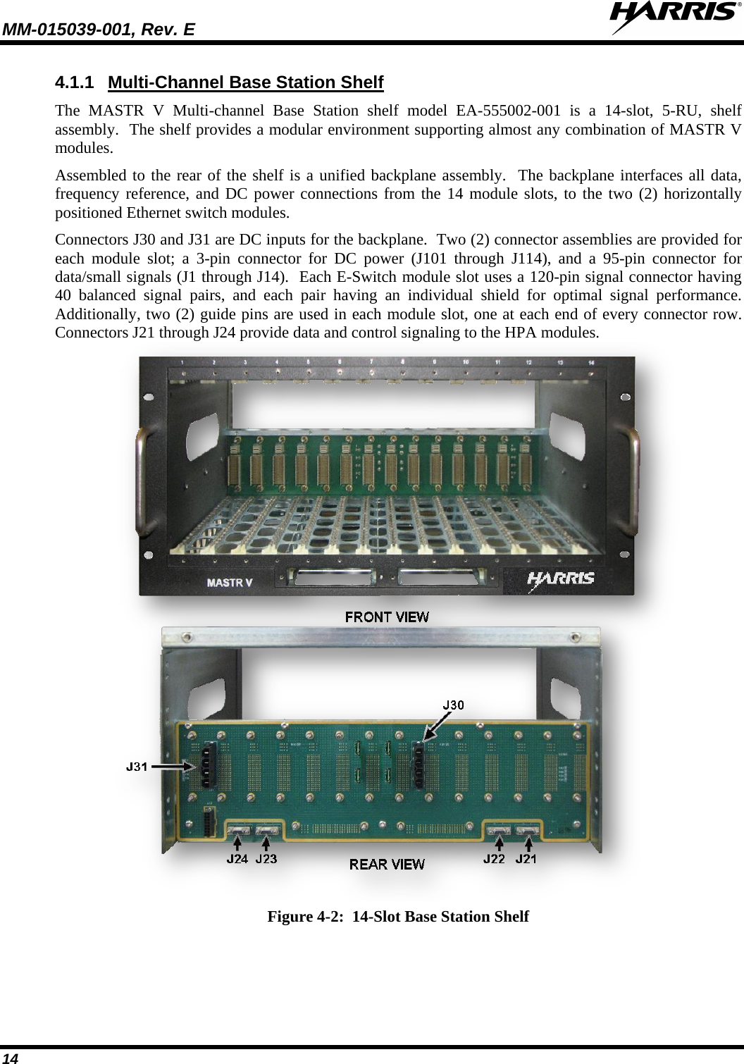
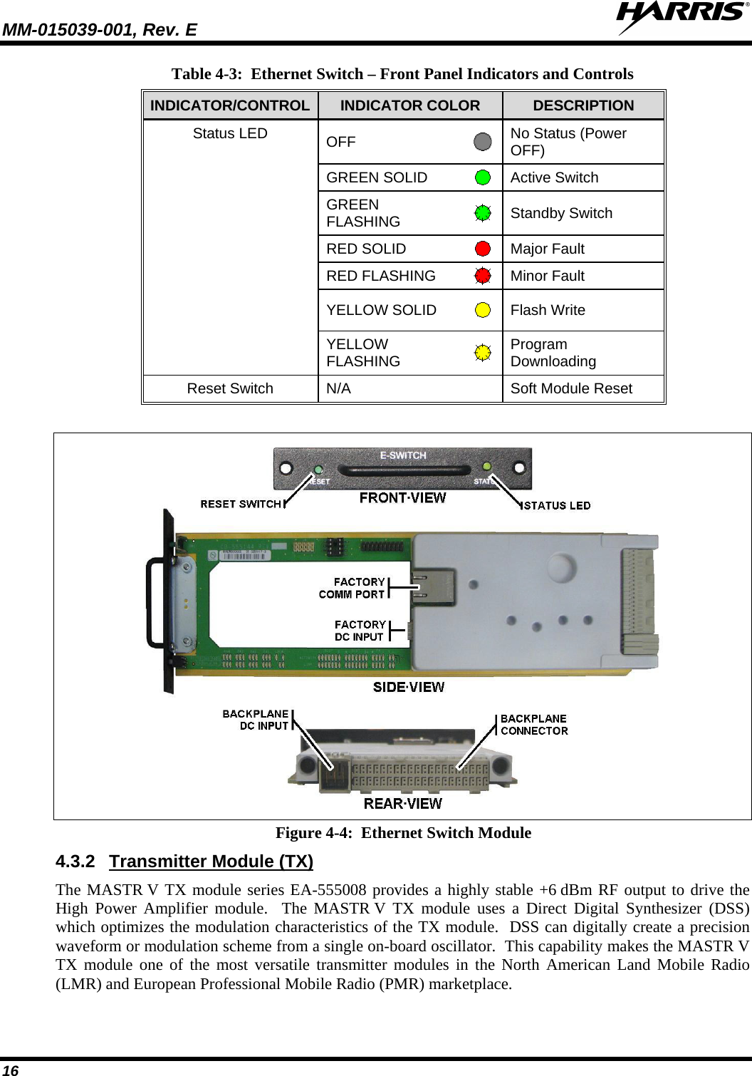
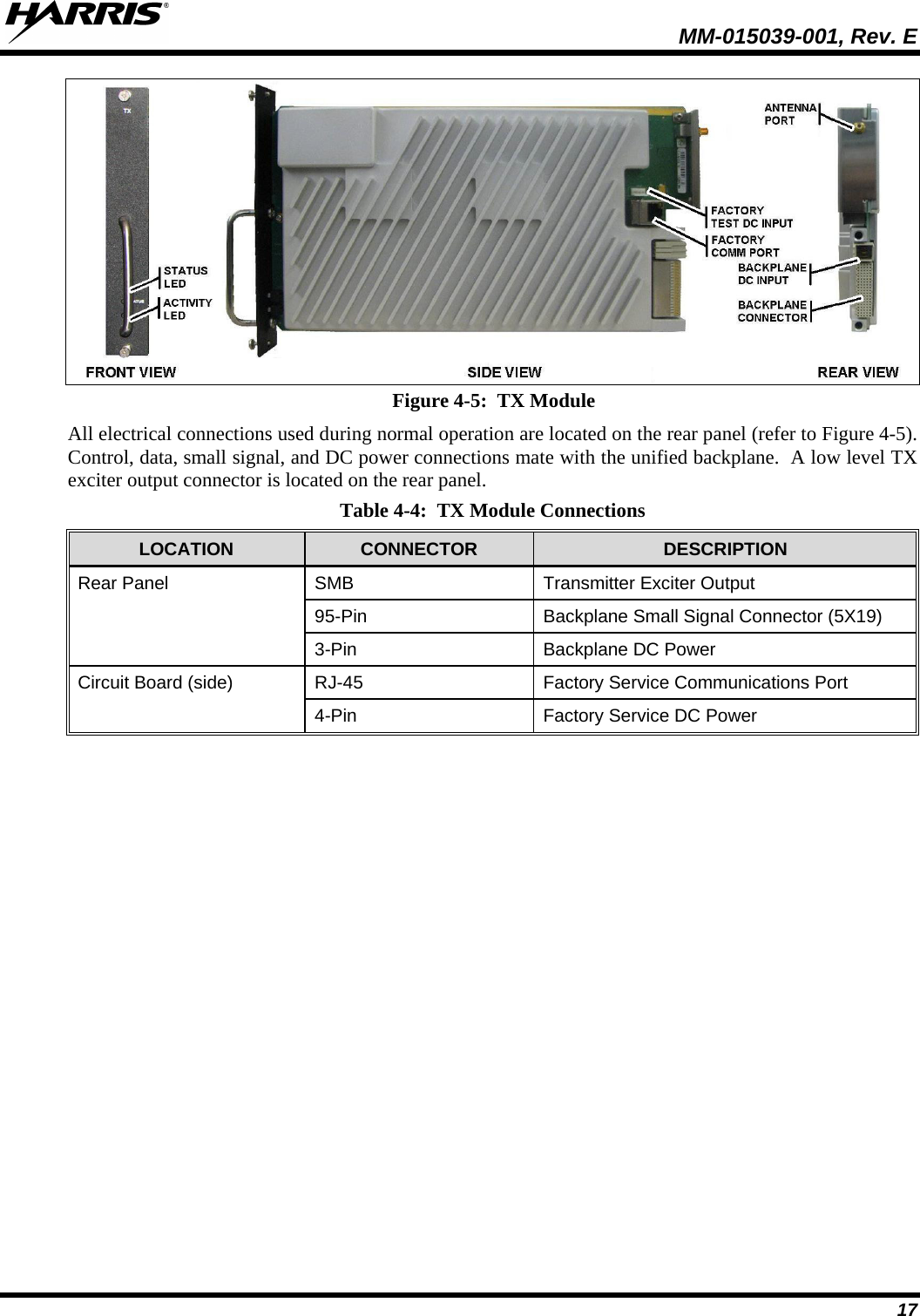
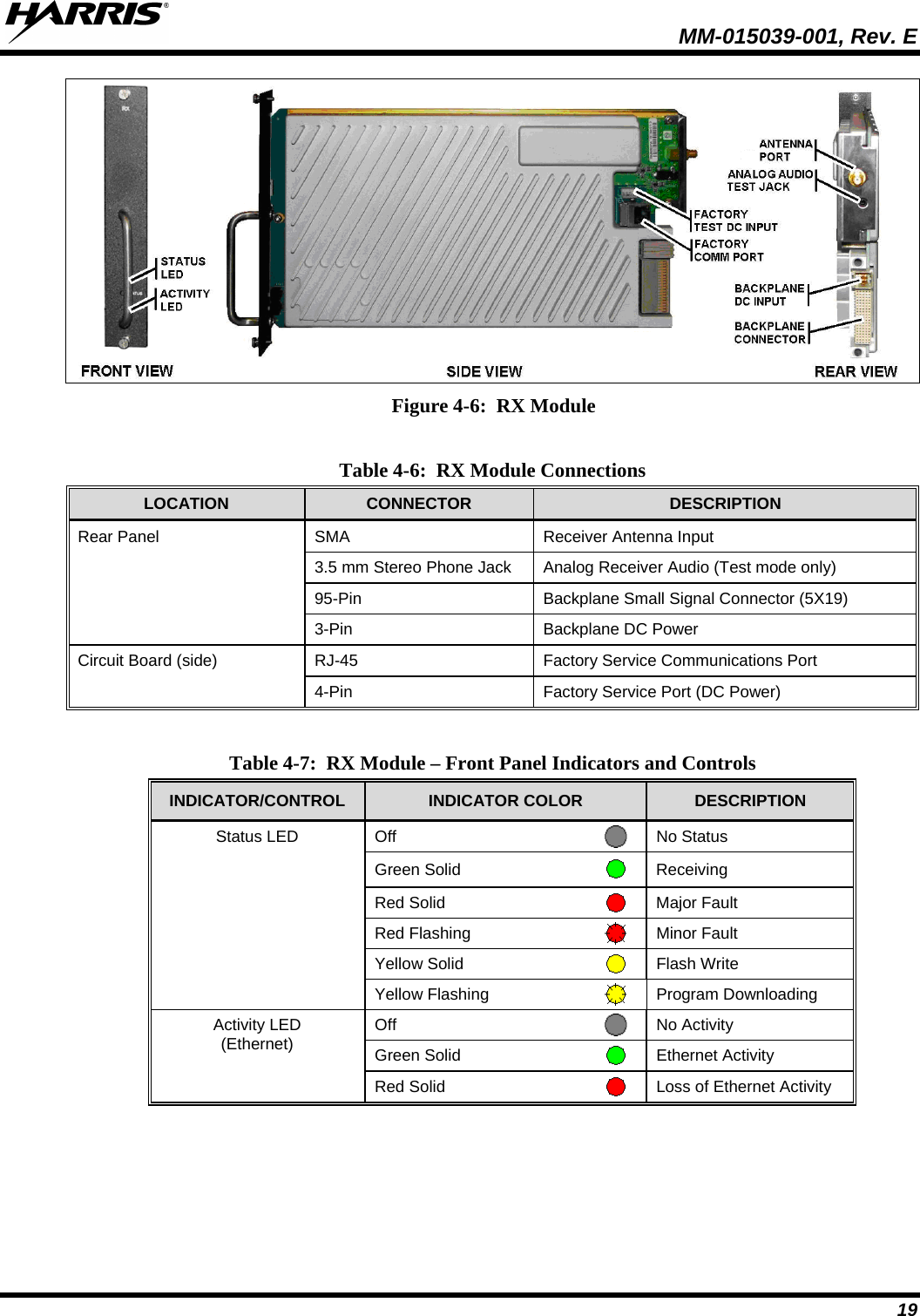
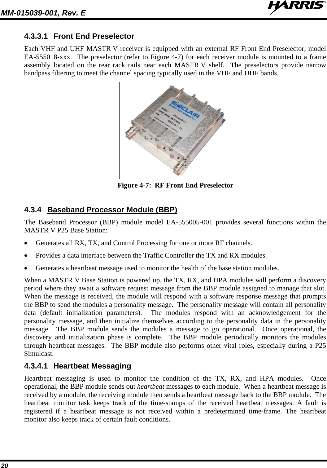
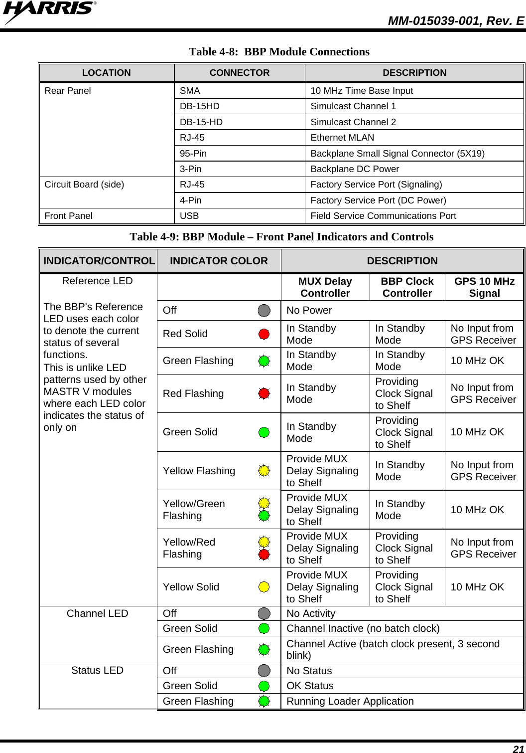
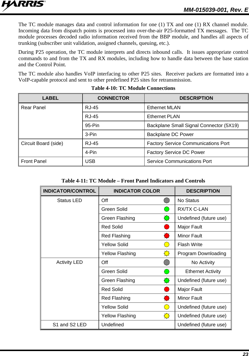
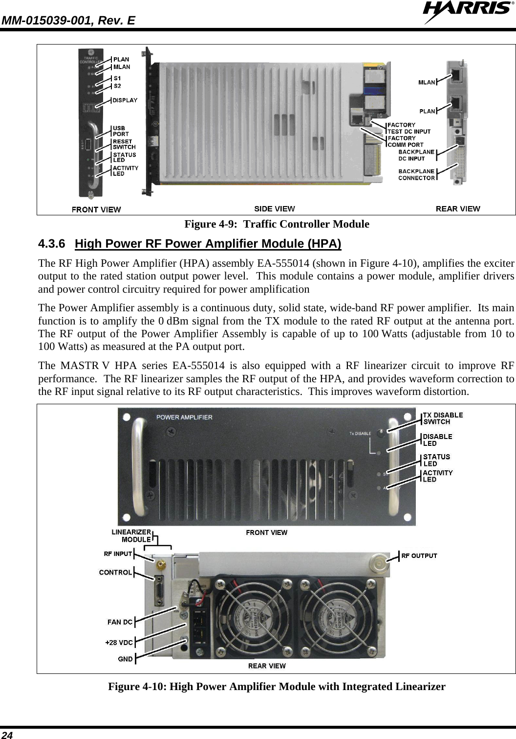
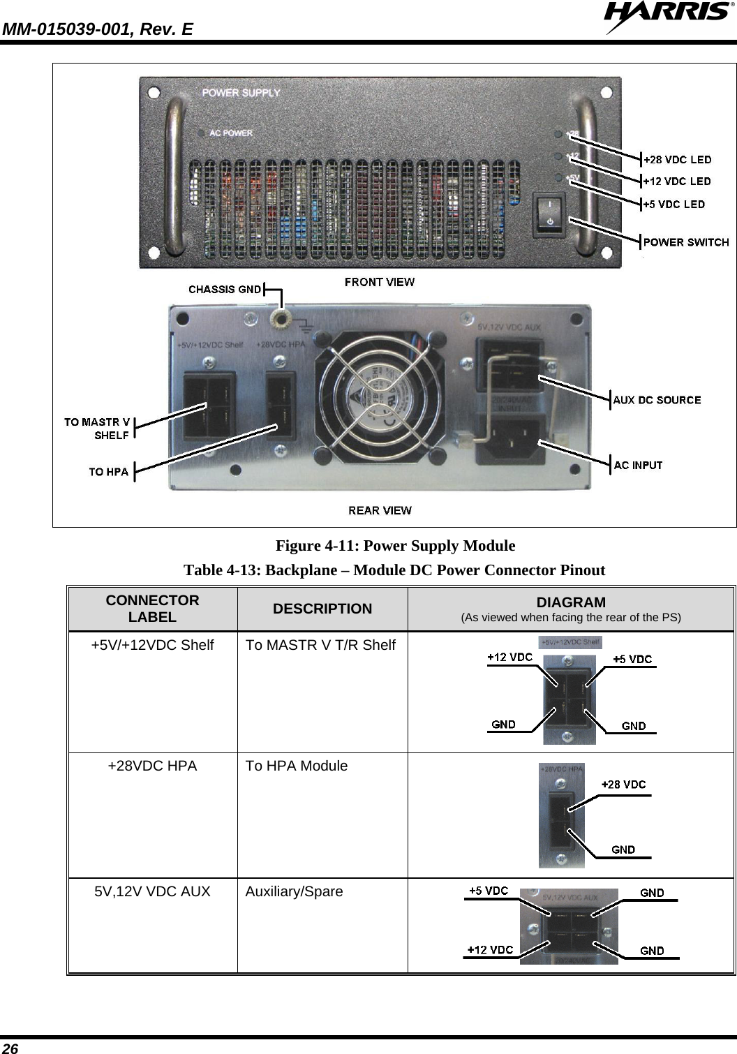
HARRIS TR-0100-E Base Station Transceiver 470-494 MHz band User Manual MM 015039 001 Rev E MASTR V Base Station

HARRIS CORPORATION Base Station Transceiver 470-494 MHz band MM 015039 001 Rev E MASTR V Base Station

MM-015039-001rE

 Overview Manual MM-015039-001 Rev. E, Sep/12    MASTR® V Base Station
MM-015039-001, Rev. E     2 MANUAL REVISION HISTORY REV DATE REASON FOR CHANGE B  Jul/10 Updated LED indicator tables and graphics.  Added equipment weights, dimensions, and VIDA secure Information Assurance information. C  Mar/11 Updated product specifications. D  Jun/11 Updated VHF regulatory and product information. E  Sep/12 Added new DC distribution panels (EA-555019-003 and EA-555019-004), P25 Phase 2 information, and regulatory information for UHF band. Harris Corporation, Public Safety and Professional Communications (PSPC) Business continually evaluates its technical publications for completeness, technical accuracy, and organization. You can assist in this process by submitting your comments and suggestions to the following Harris Corporation    fax your comments to: 1-434-455-6851 PSPC Business    or Technical Publications    e-mail us at:  PSPC_TechPubs@harris.com 221 Jefferson Ridge Parkway Lynchburg, VA 24501 ACKNOWLEDGEMENT This device is made under license under one or more of the following US patents: 4,590,473; 4,636,791; 5,148,482; 5,185,796; 5,271,017; 5,377,229; 4,716,407; 4,972,460; 5,502,767; 5,146,497; 5,164,986; 5,185,795; 5,226,084; 5,247,579; 5,491,772; 5,517,511; 5,630,011; 5,649,050; 5,701,390; 5,715,365; 5,754,974; 5,826,222; 5,870,405; 6,161,089; and 6,199,037 B1.  DVSI claims certain rights, including patent rights under aforementioned U.S. patents, and under other U.S. and foreign patents and patents pending.  Any use of this software or technology requires a separate written license from DVSI. CREDITS Harris, assuredcommunications, VIDA, EDACS, NetworkFirst, and OpenSky are registered trademarks of Harris Corporation.  AMBE is a registered trademark and IMBE, AMBE+, and AMBE+2 are trademarks of Digital Voice Systems, Inc.  All brand and product names are trademarks, registered trademarks, or service marks of their respective holders. NOTICE! The material contained herein is subject to U.S. export approval. No export or re-export is permitted without written approval from the U.S. Government. Rated: EAR99; in accordance with U.S. Dept. of Commerce regulations 15CFR774, Export Administration Regulations. Information and descriptions contained herein are the property of Harris Corporation. Such information and descriptions may not be copied or reproduced by any means, or disseminated or distributed without the express prior written permission of Harris Corporation, PSPC Business, 221 Jefferson Ridge Parkway, Lynchburg, VA 24501. Repairs to this equipment should be made only by an authorized service technician or facility designated by the supplier. Any repairs, alterations or substitutions of recommended parts made by the user to this equipment not approved by the manufacturer could void the user's authority to operate the equipment in addition to the manufacturer's warranty.  This product conforms to the European Union WEEE Directive 2002/96/EC.  Do not dispose of this product in a public landfill. Take it to a recycling center at the end of its life. This manual is published by Harris  Corporation without any warranty. Improvements and changes to this manual necessitated by typographical errors, inaccuracies of current information, or improvements to programs and/or equipment, may be made by Harris Corporation at any time and without notice. Such changes will be incorporated into new editions of this manual. No part of this manual may be reproduced or transmitted in any form or by any means, electronic or mechanical, including photocopying and recording, for any purpose, without the express written permission of Harris Corporation. Copyright © 2009-2012, Harris Corporation. All rights reserved.
  MM-015039-001, Rev. E 3 TABLE OF CONTENTS Section Page 1  REGULATORY AND SAFETY INFORMATION ...................................................................................... 5 1.1 SAFETY SYMBOL CONVENTIONS .................................................................................................. 5 1.2 IMPORTANT SAFETY INSTRUCTIONS ........................................................................................... 5 1.3 MAXIMUM PERMISSIBLE EXPOSURE LIMITS ............................................................................. 6 1.4 DETERMINING MPE RADIUS ........................................................................................................... 7 1.5 SAFETY TRAINING INFORMATION ................................................................................................ 7 1.6 REGULATORY APPROVALS ............................................................................................................. 8 1.6.1 Federal Communications Commission ...................................................................................... 8 1.6.2 Industry Canada ......................................................................................................................... 9 2  SPECIFICATIONS ........................................................................................................................................ 10 3  INTRODUCTION .......................................................................................................................................... 12 4  MASTR V BASE STATION OVERVIEW .................................................................................................. 13 4.1  MULTI-CHANNEL BASE STATION SHELF ASSEMBLY ............................................................ 13 4.1.1 Multi-Channel Base Station Shelf ........................................................................................... 14 4.2 HIGH POWER AMPLIFIER/POWER SUPPLY SHELF ASSEMBLY ............................................. 15 4.3 MASTR V MODULES ........................................................................................................................ 15 4.3.1 Ethernet Switch (E-Switch) ..................................................................................................... 15 4.3.2 Transmitter Module (TX) ........................................................................................................ 16 4.3.3 Receiver Module (RX) ............................................................................................................ 18 4.3.4 Baseband Processor Module (BBP) ......................................................................................... 20 4.3.5 Traffic Controller Module (TC)............................................................................................... 22 4.3.6 High Power RF Power Amplifier Module (HPA) ................................................................... 24 4.3.7 AC and DC Power Distribution ............................................................................................... 27 4.4 RACK AND CABINET ASSEMBLIES .............................................................................................. 30 4.4.1 DC-to-AC Inverter ................................................................................................................... 30 5  PROGRAMMING, TEST, AND DIAGNOSTICS ...................................................................................... 31 5.1 VIDA DEVICE MANAGER ............................................................................................................... 31 5.2 TEST AND DIAGNOSTICS ............................................................................................................... 31 6  REFERENCE MANUALS ............................................................................................................................ 32 7  CUSTOMER SERVICE ................................................................................................................................ 33 7.1 TECHNICAL SUPPORT ..................................................................................................................... 33 7.1.1 Tech-Link Online Services ...................................................................................................... 33 7.2 CUSTOMER CARE ............................................................................................................................ 33 WARRANTY ......................................................................................................................................................... 35
MM-015039-001, Rev. E     4 TABLE OF CONTENTS Section Page FIGURES Figure 3-1:  MASTR V Multi-Channel Base Station Shelf Equipped with One (1) RF Channel .............................. 12 Figure 4-1:  MASTR V MHz Base Station Shelf equipped with Four (4) RF Channels ........................................... 13 Figure 4-2:  14-Slot Base Station Shelf ..................................................................................................................... 14 Figure 4-3:  MASTR V HPA/PS Shelf Assembly (Shown with HPA and PS Installed) ........................................... 15 Figure 4-4:  Ethernet Switch Module ........................................................................................................................ 16 Figure 4-5:  TX Module ............................................................................................................................................. 17 Figure 4-6:  RX Module ............................................................................................................................................ 19 Figure 4-7:  RF Front End Preselector ....................................................................................................................... 20 Figure 4-8:  BaseBand Processor Module ................................................................................................................. 22 Figure 4-9:  Traffic Controller Module ...................................................................................................................... 24 Figure 4-10: High Power Amplifier Module with Integrated Linearizer ................................................................... 24 Figure 4-11: Power Supply Module ........................................................................................................................... 26 Figure 4-12: Dual AC Power Distribution Strip ........................................................................................................ 27 Figure 4-13: EA-555019-001 – -48 VDC Low Power DC Distribution Strip ........................................................... 28 Figure 4-14: EA-555019-002 – -48 VDC High Power DC Distribution Strip .......................................................... 28 Figure 4-15: EA-555019-003 – Enhanced -48 VDC Low Power DC Distribution Strip .......................................... 29 Figure 4-16: EA-555019-004 – Enhanced -48 VDC High Power DC Distribution Strip .......................................... 29 Figure 4-17: 86-inch Open Rack Assembly ............................................................................................................... 30 Figure 4-18: 86-inch Extra Deep Cabinet .................................................................................................................. 30 Figure 4-19: DC-to-AC Inverter Used to Power the Cabinet Fan at DC-Powered Sites ........................................... 30  TABLES Table 4-1:  Typical Module Slot Assignments for MASTR V Base Stations ............................................................ 13 Table 4-2:  E-Switch Module Connections ................................................................................................................ 15 Table 4-3:  Ethernet Switch – Front Panel Indicators and Controls ........................................................................... 16 Table 4-4:  TX Module Connections ......................................................................................................................... 17 Table 4-5:  TX Module – Front Panel Indicators and Controls ................................................................................. 18 Table 4-6:  RX Module Connections ......................................................................................................................... 19 Table 4-7:  RX Module – Front Panel Indicators and Controls ................................................................................. 19 Table 4-8:  BBP Module Connections ....................................................................................................................... 21 Table 4-9: BBP Module – Front Panel Indicators and Controls ................................................................................ 21 Table 4-10: TC Module Connections ........................................................................................................................ 23 Table 4-11: TC Module – Front Panel Indicators and Controls ................................................................................. 23 Table 4-12: HPA Front Panel Indicators and Switches ............................................................................................. 25 Table 4-13: Backplane – Module DC Power Connector Pinout ................................................................................ 26 Table 4-14: PS Front Panel Indicators and Switches ................................................................................................. 27 Table 6-1:  Reference Manuals .................................................................................................................................. 32
  MM-015039-001, Rev. E 5 1  REGULATORY AND SAFETY INFORMATION 1.1 SAFETY SYMBOL CONVENTIONS The following conventions are used throughout this manual to alert the user to general safety precautions that must be observed during all phases of operation, service, and repair of this product. Failure to comply with these precautions or with specific warnings elsewhere violates safety standards of design, manufacture, and intended use of the product.  Harris Corporation assumes no liability for the customer's failure to comply with these standards.  The WARNING symbol calls attention to a procedure, practice, or the like, which, if not correctly performed or adhered to, could result in personal injury. Do not proceed beyond a WARNING symbol until the conditions identified are fully understood or met.     The CAUTION symbol calls attention to an operating procedure, practice, or the like, which, if not performed correctly or adhered to, could result in damage to the equipment or severely degrade equipment performance.    The NOTE symbol calls attention to supplemental information, which may improve system performance or clarify a process or procedure.    The ESD symbol calls attention to procedures, practices, or the like, which could expose equipment to the effects of Electro-Static Discharge. Proper precautions must be taken to prevent ESD when handling circuit boards or modules.    The electrical hazard symbol is a WARNING indicating there may be an electrical shock hazard present.  1.2 IMPORTANT SAFETY INSTRUCTIONS • Read these instructions. • Keep these instructions. • Heed all warnings. • Follow all instructions. • Do not use this apparatus near water. • Clean only with dry cloth. • Do not block any ventilation openings.  Install in accordance with the manufacturer’s instructions. WARNINGCAUTIONNOTE
MM-015039-001, Rev. E     6 • Do not install near any heat sources such as radiators, heat registers, stoves, or other apparatus (including amplifiers) that produce heat. • Do not defeat the safety purpose of the polarized or grounding-type plug. A polarized plug has two blades with one wider than the other. A grounding type plug has two blades and a third grounding prong. The wide blade or the third prong is provided for your safety. If the provided plug does not fit into your outlet, consult an electrician for replacement of the obsolete outlet. • Protect the power cord from being walked on or pinched particularly at plugs, convenience receptacles, and the point where they exit from the apparatus. • Only use attachments/accessories specified by the manufacturer. • Use only with the cart, stand, tripod, bracket, or table specified by the manufacturer, or sold with the apparatus. When a cart is used, use caution when moving the cart/apparatus combination to avoid injury from tip-over.  • Refer all servicing to qualified service personnel. Servicing is required when the apparatus has been damaged in any way, such as when the power-supply cord or plug is damaged, liquid has been spilled or objects have fallen into the apparatus, the apparatus has been exposed to rain or moisture, does not operate normally, or has been dropped. • Warning: The lightning bolt signifies an alert to the user of the presence of un-insulated “dangerous voltage” within the product’s enclosure that may be of significant magnitude to constitute a risk of electric shock to persons.  • Warning: The exclamation point alerts the user to the presence of important operation and maintenance (service) instructions in the literature accompanying the product. • Outdoor Use Warning: To reduce the risk of Fire or Electric Shock, Do Not Expose This Apparatus to Rain or Moisture. • Wet Location Warning: Apparatus shall not be exposed to dripping or splashing and no objects filled with liquids, such as vases, shall be placed on the apparatus. 1.3 MAXIMUM PERMISSIBLE EXPOSURE LIMITS DO NOT TRANSMIT with this base station and antenna when persons are within the Maximum Permissible Exposure (MPE) Radius of the antenna.  The MPE Radius is the minimum distance from the antenna axis that ALL persons should maintain in order to avoid RF exposure higher than the allowable MPE level set by the FCC.
  MM-015039-001, Rev. E 7  Failure to observe these limits may allow all persons within the MPE radius to experience RF radiation absorption, which exceeds the FCC maximum permissible exposure (MPE) limit.  It is the responsibility of the base station operator to ensure that the maximum permissible exposure limits are observed at all times during base station transmission.  The base station licensee is to ensure that no bystanders are within the radius limits. 1.4 DETERMINING MPE RADIUS The Maximum Permissible Exposure radius is unique for each site and is determined during site licensing time based on the complete installation environment (i.e.  co-location, antenna type, transmit power level, etc.).  Determination of the MPE distance is the responsibility of the installation licensee.  Calculation of the MPE radius is required as part of the site licensing procedure with the FCC. 1.5 SAFETY TRAINING INFORMATION   Your MASTR®V base station generates RF electromagnetic energy during transmit mode.  This base station is designed for and classified as “occupational use only” meaning it must be used only in the course of employment by individuals aware of the hazards and the ways to minimize such hazards.  This base station is not intended for use by the “general population” in an uncontrolled environment.  It is the responsibility of the base station licensee to ensure that the maximum permissible exposure limits determined in the previous section are observed at all times during transmission.  The base station licensee is to ensure that no bystanders come within the radius of the maximum permissible exposure limits. When licensed by the FCC, this base station complies with the FCC RF exposure limits when persons are beyond the MPE radius of the antenna.  In addition, your Harris base station installation complies with the following Standards and Guidelines with regard to RF energy and electromagnetic energy levels and evaluation of such levels for exposure to humans: • FCC OET Bulletin 65 Edition 97-01 Supplement C, Evaluating Compliance with FCC Guidelines for Human Exposure to Radio Frequency Electromagnetic Fields. • American National Standards Institute (C95.1 – 1992), IEEE Standard for Safety Levels with Respect to Human Exposure to Radio Frequency Electromagnetic Fields, 3 kHz to 300 GHz. • American National Standards Institute (C95.3 –  1992), IEEE Recommended Practice for the Measurement of Potentially Hazardous Electromagnetic Fields – RF and Microwave.   To ensure that your exposure to RF electromagnetic energy is within the FCC allowable limits for occupational use, do not operate the base station in a manner that would create an MPE distance in excess of that allowable by the FCC.   This equipment generates or uses radio frequency energy.  Any changes or modifications to this equipment not expressly approved by Harris  Corporation  may cause harmful interference and could void the user’s authority to operate the equipment. WARNINGWARNINGCAUTIONCAUTION
MM-015039-001, Rev. E     8 1.6 REGULATORY APPROVALS 1.6.1 Federal Communications Commission The transmitting device described within this manual has been tested and found to meet the following regulatory requirements: FCC FILING DATA FOR MASTR V BASE STATION FREQUENCY BAND (MHz) POWER OUTPUT (ADJUSTABLE) (Watts) FCC TYPE ACCEPTANCE NUMBER APPLICABLE FCC RULES 470.00625 – 493.99375 10 – 100 OWDTR-0100-E  Part 90 494.00625 – 511.99375 10 – 100 OWDTR-0101-E  Part 90 764 – 776 10 – 100 OWDTR-0057-E  Part 90 851 – 869 10 – 100 OWDTR-0053-E  Part 90 150.0125 – 173.9875 10 – 100 OWDTR-0065-E  Part 90 This receiver associated with this transmitting device has been tested and declared to meet the regulatory requirements defined in the following sub-sections. Associated FCC labeling may be found on page 2. 1.6.1.1 FCC Compliance This device complies with Part 15 of the FCC Rules. Operation is subject to the following two conditions:  1. This device may not cause harmful interference, and, 2. This device must accept any interference received, including interference that may cause undesired operation. 1.6.1.2 Information to the User This equipment has been tested and found to comply with the limits for a Class A digital device, pursuant to Part 15 of the FCC Rules.  These limits are designed to provide reasonable protection against harmful interference in a residential installation.  This equipment  does generate, use,  and can radiate radio frequency energy and, if not installed and used in accordance with the instructions, may cause harmful interference to radio communications.  However, there is no guarantee that interference will not occur in a particular installation.  If this equipment does cause harmful interference to radio or television reception, which can be determined by turning the equipment off and on, the user is encouraged to try to correct the interference by one or more of the following measures: • Reorient or relocate the receiving antenna. • Increase the separation between the equipment and receiver. • Connect the equipment into an AC  outlet on a circuit different from that which the receiver is connected. • Consult the dealer or an experienced radio/TV technician for help.
  MM-015039-001, Rev. E 9  1.6.2 Industry Canada  INDUSTRY CANADA FILING DATA FOR MASTR V BASE STATION FREQUENCY BAND (MHZ) INDUSTRY CANADA CERTIFICATION NUMBER APPLICABLE INDUSTRY CANADA RULES 470.00625 – 493.99375 3636B-0100 RSS-119 494.00625 – 511.99375 3636B-0101 RSS-119 764 – 776 3636B-0057 RSS-119 851 – 869 3636B-0053 RSS-119 150 – 174 3636B-0065 RSS-119 This Class A digital apparatus complies with Canadian ICES-003. Cet appareil numérique de la classe A est conforme à la norme NMB-003 du Canada. WARNING The installer of this radio equipment must ensure that the antenna is located or pointed such that it does not emit RF field in excess of Health Canada limits for the general population; consult Safety Code 6, obtainable from Heath Canada’s website www.hc-sc.gc.ca/rpb. L'installateur de cet équipement radio doit garantir que l'antenne est trouvée ou montrée tel qu'il n'émet pas de champ de RF plus de la Santé les limites du Canada pour la population générale; consultez le Code 6 de Sécurité, disponible de la Lande le site Internet du Canada www.hc-sc.gc.ca/rpb. The present apparatus complies with CNR of Industry Canada applicable to apparatuses radio exempt from license. Working is allowed on both following conditions: (1) the apparatus should not produce of disturbance, and (2) the user of the apparatus must accept any been subjected radio electrical disturbance, even if disturbance is likely to compromise functioning. Le présent appareil est conforme aux CNR d'Industrie Canada applicables aux appareils radio exempts de licence. L'exploitation est autorisée aux deux conditions suivantes : (1) l'appareil ne doit pas produire de brouillage, et (2) l'utilisateur de l'appareil doit accepter tout brouillage radioélectrique subi, même si le brouillage est susceptible d'en compromettre le fonctionnement.
MM-015039-001, Rev. E     10 2  SPECIFICATIONS General Specifications1  Duty Cycle (EIA) Continuous: Transmit and Receive at 100% Operating Temperature: -22°F to +140°F (-30°C to +60°C) Humidity (EIA): 90% at 122°F (50°C) Non-condensing AC Power Supply:   Input Power Source: 90 – 240 VAC (nominal), 47~63 Hz Source Power Drain: 1000 watts per channel (max.) @ 120 VAC 600 watts per channel (typical) @ 120 VAC Input Power Efficiency:  > 85% at full load (120 VAC) > 82.5% at full Load (<100 VAC) Power Supply Outputs:  +28.0 VDC ± 0.2V at 25.0 Amps +12.0 VDC ± 0.2V at 2.8 Amps +5.0 VDC ± 0.2V at 28.0 Amps Altitude:  Operational: Up to 15,000 ft (4,570 m) Shippable: Up to 50,000 ft (15,250 m) Transmitter Specifications  Frequency Ranges: 150 – 174 MHz (TX Module # EA-555008-002)  380 – 400 MHz (TX Module # EA-555008-005)2  470 – 494 MHz (TX Module # EA-555008-009)  494 – 512 MHz (TX Module # EA-555008-010)  764 – 776 MHz (TX Module # EA-555008-011)  851 – 869 MHz (TX Module # EA-555008-012) RMS RF Output Power3: 10 – 100 Watts RF Output Impedance: 50 ohms Antenna Connection: Type N Female on High Power Amplifier Power control accuracy: -0/+0.79 dB Frequency Stability: < 0.1 ppm external freq. std.   Frequency Step Size: 6.25 kHz Tuning Range: No tuning required Nominal TX Deviation: 2.544 to 3.111 kHz (per TIA-102) Modes of Modulation: C4FM, WCQPSK, HDQPSK Modulation Emission Spectrum: Per FCC Part 90 Incidental AM / AM Hum & Noise: > 50 dBc Radiated and Conducted Spurious Emissions: < -70 dBc                                                            1 Specifications  listed herein are applicable only to Harris’ MASTR V Base Station RF equipment.  Always refer to the manufacturer of third party equipment, such as Routers and Switches, for additional specifications.  Specifications listed in this manual are intended primarily for the use of the service technician. Additional specifications may be listed on the product data sheet. 2 At the time this manual was written, this device has not been authorized as required by the rules of the Federal Communications Commission. “This device is not, and may not be, offered for sale or lease, or sold or leased, until authorization is obtained.”  This device; however, may be available within the NTIA marketplace. 3 Rated power output is measured at the transmitter’s power amplifier output connector. Optional items such as power measuring devices and/or duplexers will introduce loss between the transmitter output connector and the station cabinet output connector. This loss will reduce the available power at the station connector.
  MM-015039-001, Rev. E 11 Receiver Specifications  Frequency Range: 136 – 174 MHz (RX Module # EA-555007-002)  380 – 400 MHz (RX Module # EA-555007-0052)  470 – 494 MHz (RX Module # EA-555007-009)  494 – 512 MHz (RX Module # EA-555007-010)  799 – 816 MHz (RX Module # EA-555007-011)  806 – 824 MHz (RX Module # EA-555007-012) Tuning Range: Receiver modules (all bands), No tuning required VHF/UHF – Requires external preselector tuning4 RF Input Impedance: 50 ohms Antenna Connection: SMA Female on Receiver Module (VHF/UHF – BNC female, if equipped with Preselector) Channel Spacing: 12.5 kHz Sensitivity: ≥ -119 dBm (5% BER) static, -111 faded (EIA) Selectivity: ≥ 60 dB Per TIA-102 Frequency Stability: < 0.1 ppm external freq. std. Signal Displacement Bandwidth: ± 1.0 kHz Per TIA-102 Spurious and Image Rejection: ≥ 90 dB Weights and Dimensions5 WEIGHT lbs. (kg.) DEPTH in (cm) WIDTH in (cm) HEIGHT6 in (cm) or RU Rack, 86 in., Deep, 3-rail, 46-RU: 235 (107) 21.0 (53.3) 21.0. (53.3) 85.5 (217.0) Cabinet, 86 in., Extra Deep, 45-RU 355 (161.0) 31.6 (80.3) 23 (58.4) 86.8 (220.5) 14-Slot Shelf Assembly (w/o modules): 16.5 (7.5) 15.0 (38.1) 19.0 (48.3)  5-RU High Power Amplifier Shelf (Chassis only): 5.0 (2.3)  19.0 (48.3) 2-RU Power Supply Unit (PSU): 9.0 (4.1) 13 (33.0) 8.6 (21.8) 3.5 (8.9) RF High Power Amplifier (HPA): 11.5 (5.2) 13 (33.0) 8.6 (21.8) 3.5 (8.9) Ethernet Switch: 0.8 (0.36) 12.25 (31.1) 0.625 (1.6) 4.25 (10.8) Transmitter (TX) Module: 2.5 (1.1) 12.6 (32.0) 0.82 (2.1) 7.25 (18.4) Receiver (RX) Module: 2.5 (1.1) 12.6 (32.0) 0.82 (2.1) 7.25 (18.4) Traffic Controller (TC) Module: 2.5 (1.1) 12.6 (32.0) 0.82 (2.1) 7.25 (18.4) Baseband Module (BB): 2.5 (1.1) 12.6 (32.0) 0.82 (2.1) 7.25 (18.4)                                                             4  Refer to manufacturer’s specifications for the specific preselector. 5  Weights and dimensions are approximate, and represent the minimum space required to install the device.  In most cases, measurements include handles, brackets, knobs, controls, and other hardware that is permanently affixed to the device.  Measurements do not include distances for cable bends, unless the cable is permanently affixed to the equipment. 6  For 19” rack mountable equipment, heights may be defined in Rack Units (RU).  One (1) RU is equal to 1.75 in. (4.45 cm).  For example: 2-RU equals 3.5 in. (8.9 cm), 3-RU equals 5.25 in. (13.3 cm), etc.
MM-015039-001, Rev. E     12 3  INTRODUCTION The MASTR V Base Station is a P25 Phase 2 capable transceiver.  The station is fully upgradable to P25 Phase II.  The MASTR V Base Station is a digital, IP based, LMR communications base station operating within a compact shelf design.  It supports IP-based remote software uploads and configuration.  IP-based programming may be accomplished using the VIDA Device Manager programming tool.  Network and programming communications ports may be configured for VIDA secure shell operation to meet Information Assurance (IA) requirements.  A built-In Self Test (BIST) feature provides improved performance through remote diagnosis which minimizes down time. The MASTR V Base Station uses a 14-slot modular multi-channel T/R shelf assembly (refer to  Figure 3-1) and a 2-slot High Power Amplifier/Power Supply (HPA/PS) shelf assembly.  Modules may include BaseBand Processors, Traffic Controllers, TX, and RX modules.  Blank panels for the main module slots (MA-555413) and for the E-Switch slots (MA-555417) are installed in unused slots. The TX module uses a factory programmable IQ modulator circuit capable of generating most any LMR modulation format into a Direct Digital Synthesis (DDS) TX exciter circuit.  Additionally, the HPA may be equipped with a Linearizer module for improved amplitude and phase noise characteristics in S-C4FM or similar modulation modes. The RX module includes integrated front end and IF circuitry.  The RX module also uses IQ demodulation circuitry.  The IQ demodulator is factory programmable and can decode most amplitude and phase modulation characteristic, making it capable of receiving most analog or digital LMR modulation format. The Multi-channel T/R shelf requires +12 VDC and +5 VDC.  The HPA requires +28 VDC.  The station may be equipped with a 120/240 VAC switching power supply.  The T/R shelf occupies 5-RU spaces.  The HPA/PS shelf occupies 2-RU spaces (per TX channel).  Figure 3-1:  MASTR V Multi-Channel Base Station Shelf Equipped with One (1) RF Channel
  MM-015039-001, Rev. E 13 4  MASTR V BASE STATION OVERVIEW 4.1 MULTI-CHANNEL BASE STATION SHELF ASSEMBLY The MASTR V multi-channel base station shelf assembly is a unified sub-rack design providing 14 identical vertical module slots.  Also included are two (2) horizontal slots located under the 14 vertical slots, and used to connect the built-in main and redundant Ethernet Switch modules. A backplane assembly (refer to ) provides data and DC power connections to each vertical slot, and the two Ethernet Switch module slots.  The multi-channel base station shelf, and each module, is equipped with a pull handle for improved handling of the equipment.  Table 4-1:  Typical Module Slot Assignments for MASTR V Base Stations SLOT # MODULE    SLOT # MODULE 1  Transmitter Module (Channel 1)    8  Transmitter Module (Channel 3) 2  Receiver Module (Channel 1)    9  Receiver Module (Channel 3) 3  Transmitter Module (Channel 2)    10 Transmitter Module (Channel 4) 4  Receiver Module (Channel 2)    11 Receiver Module (Channel 4) 5  Baseband Module (Channel 1 / 2)    12 Baseband Module (Channel 3 / 4) 6  Traffic Controller (Channel 1)    13 Traffic Controller (Channel 3) 7  Traffic Controller (Channel 2)    14 Traffic Controller (Channel 4) E1  E-Switch # 1 (Main)    E2  E-Switch #2 (Redundant)    Figure 4-1:  MASTR V MHz Base Station Shelf equipped with Four (4) RF Channels
MM-015039-001, Rev. E     14 4.1.1 Multi-Channel Base Station Shelf The MASTR V Multi-channel Base Station shelf model EA-555002-001 is a 14-slot,  5-RU, shelf assembly.  The shelf provides a modular environment supporting almost any combination of MASTR V modules. Assembled to the rear of the shelf is a unified backplane assembly.  The backplane interfaces all data, frequency reference, and DC power connections from the 14 module slots, to the two (2) horizontally positioned Ethernet switch modules. Connectors J30 and J31 are DC inputs for the backplane.  Two (2) connector assemblies are provided for each module slot;  a  3-pin connector  for  DC power (J101 through J114), and  a  95-pin connector  for data/small signals (J1 through J14).  Each E-Switch module slot uses a 120-pin signal connector having 40 balanced signal pairs, and each pair having an individual shield for  optimal signal performance.  Additionally, two (2) guide pins are used in each module slot, one at each end of every connector row. Connectors J21 through J24 provide data and control signaling to the HPA modules.  Figure 4-2:  14-Slot Base Station Shelf
  MM-015039-001, Rev. E 15 4.2 HIGH POWER AMPLIFIER/POWER SUPPLY SHELF ASSEMBLY The High Power Amplifier (HPA) (refer to Section 4.3.6) and the Power Supply (PS) (refer to Section 4.3.6.1) are installed in a 19” rack mountable, 2-slot metal shelf, model MA-555003 (refer to Figure 4-3).  The HPA/PS shelf is a mechanical-only assembly with no electrical components.  Figure 4-3:  MASTR V HPA/PS Shelf Assembly (Shown with HPA and PS Installed) 4.3 MASTR V MODULES For P25 operation, the following station modules may be installed in the MASTR V Base Station shelf: • TX module • RX module • Baseband Processor Module • Traffic Controller Module • High Power Amplifier Module • Power Supply Module • Ethernet Switch 4.3.1 Ethernet Switch (E-Switch) Communications with the MASTR V base station modules is provided by a built-in Ethernet Switch module EA-555012-001 located under main module shelf.  A second position is provided under the main module shelf for a redundant Ethernet Switch module. Ethernet communications are utilized to pass voice and data transmissions, management, and control data between the Traffic Controller and supporting MASTR V modules via the Ethernet Switches.   Table 4-2:  E-Switch Module Connections LOCATION  CONNECTOR  DESCRIPTION Circuit Board (side) RJ-45 Factory Service Communications Port 4-Pin Factory Service DC Power  Rear Panel 120-Pin Backplane Connection (40 pair w/Shield) 3-Pin Backplane DC Power
MM-015039-001, Rev. E     16 Table 4-3:  Ethernet Switch – Front Panel Indicators and Controls INDICATOR/CONTROL INDICATOR COLOR DESCRIPTION Status LED OFF   No Status (Power OFF) GREEN SOLID  Active Switch GREEN FLASHING  Standby Switch RED SOLID  Major Fault RED FLASHING  Minor Fault YELLOW SOLID  Flash Write YELLOW FLASHING  Program Downloading Reset Switch N/A    Soft Module Reset   Figure 4-4:  Ethernet Switch Module 4.3.2 Transmitter Module (TX) The MASTR V TX module series EA-555008 provides a highly stable +6 dBm RF output to drive the High Power Amplifier module.  The MASTR V TX module uses a Direct Digital Synthesizer (DSS) which optimizes the modulation characteristics of the TX module.  DSS can digitally create a precision waveform or modulation scheme from a single on-board oscillator.  This capability makes the MASTR V TX module one of the most versatile transmitter modules in the North American Land Mobile Radio (LMR) and European Professional Mobile Radio (PMR) marketplace.
  MM-015039-001, Rev. E 17  Figure 4-5:  TX Module All electrical connections used during normal operation are located on the rear panel (refer to Figure 4-5).  Control, data, small signal, and DC power connections mate with the unified backplane.  A low level TX exciter output connector is located on the rear panel. Table 4-4:  TX Module Connections LOCATION  CONNECTOR  DESCRIPTION Rear Panel SMB Transmitter Exciter Output 95-Pin Backplane Small Signal Connector (5X19) 3-Pin Backplane DC Power Circuit Board (side) RJ-45 Factory Service Communications Port 4-Pin Factory Service DC Power
MM-015039-001, Rev. E     18 Table 4-5:  TX Module – Front Panel Indicators and Controls INDICATOR/CONTROL INDICATOR COLOR DESCRIPTION Status LED OFF  No Status GREEN SOLID  Transmitting GREEN FLASHING  Exciter Mode RED SOLID  Major Fault RED FLASHING  Minor Fault YELLOW SOLID  Flash Write (during program modes) Alternately, No Linearizer Power Loop Packets YELLOW FLASHING  Program Downloading Activity LED (Ethernet) OFF  No Activity GREEN SOLID  Ethernet Activity RED SOLID  Loss of Ethernet Activity 4.3.3 Receiver Module (RX) The MASTR V Receiver (RX) modules, model EA-555007, are dual-IF conversion receivers.  The receiver uses a Sigma-Delta analog to digital converter to process the incoming IF signal.  The output of the  analog-to-digital converter is a complex pair of I/Q baseband digital signals.   The MASTR V RX module supports a wide range of modulation waveforms required for current and next generation public safety two-way radio communications. After IF filtering and down-conversion, received signals are digitized into I and Q information and sent to the Baseband Processor module via the backplane Ethernet.  The Baseband Processor module provides the narrow channel filtering and demodulation.  The narrow channel filters and digital demodulation is performed by the system DSP, giving the MASTR V receiver the flexibility needed in current and future LMR communications systems. All bands of MASTR V RX modules share common design features and meet stringent receiver specifications including the following: • High intercept point. • Low noise figure. • 110.2 MHz IF chosen for all bands of the MASTR V. • Automatic Level Control. • Built-in 10 MHz reference; switchable to external reference derived from the baseband module (which is compatible with an external frequency standard used for Simulcast). • Low side LO injection for superior noise performance (700/800 MHz module). • Built-in hardware diagnostics (voltage supplies, PLL Lock). • Analog FM audio test jack (for factory use only). • Raw IQ data is sent to the BaseBand Processor module for demodulation.
  MM-015039-001, Rev. E 19  Figure 4-6:  RX Module  Table 4-6:  RX Module Connections LOCATION CONNECTOR DESCRIPTION Rear Panel  SMA  Receiver Antenna Input 3.5 mm Stereo Phone Jack Analog Receiver Audio (Test mode only) 95-Pin  Backplane Small Signal Connector (5X19) 3-Pin Backplane DC Power Circuit Board (side) RJ-45 Factory Service Communications Port 4-Pin Factory Service Port (DC Power)  Table 4-7:  RX Module – Front Panel Indicators and Controls INDICATOR/CONTROL INDICATOR COLOR DESCRIPTION Status LED Off  No Status Green Solid  Receiving Red Solid  Major Fault Red Flashing  Minor Fault Yellow Solid  Flash Write Yellow Flashing  Program Downloading Activity LED (Ethernet) Off  No Activity Green Solid  Ethernet Activity Red Solid  Loss of Ethernet Activity
MM-015039-001, Rev. E     20 4.3.3.1 Front End Preselector Each VHF and UHF MASTR V receiver is equipped with an external RF Front End Preselector, model EA-555018-xxx.  The preselector (refer to Figure 4-7) for each receiver module is mounted to a frame assembly located on the  rear  rack  rails  near  each MASTR V shelf.  The preselectors provide narrow bandpass filtering to meet the channel spacing typically used in the VHF and UHF bands.  Figure 4-7:  RF Front End Preselector  4.3.4 Baseband Processor Module (BBP) The Baseband Processor (BBP) module model EA-555005-001 provides several functions within the MASTR V P25 Base Station: • Generates all RX, TX, and Control Processing for one or more RF channels. • Provides a data interface between the Traffic Controller the TX and RX modules. • Generates a heartbeat message used to monitor the health of the base station modules. When a MASTR V Base Station is powered up, the TX, RX, and HPA modules will perform a discovery period where they await a software request message from the BBP module assigned to manage that slot.  When the message is received, the module will respond with a software response message that prompts the BBP to send the modules a personality message.  The personality message will contain all personality data (default initialization parameters).  The modules respond with an acknowledgement for the personality message, and then initialize themselves according to the personality data in the personality message.  The BBP module sends the modules a message to go operational.  Once operational, the discovery and initialization phase is complete.  The BBP module periodically monitors the modules through heartbeat messages.  The BBP module also performs other vital roles, especially during a P25 Simulcast. 4.3.4.1 Heartbeat Messaging Heartbeat messaging is used to monitor the condition of the TX, RX, and HPA modules.  Once operational, the BBP module sends out heartbeat messages to each module.  When a heartbeat message is received by a module, the receiving module then sends a heartbeat message back to the BBP module.  The heartbeat monitor task keeps track of the time-stamps of the received heartbeat messages. A fault is registered if a heartbeat message is not received within a predetermined time-frame. The heartbeat monitor also keeps track of certain fault conditions.
  MM-015039-001, Rev. E 21 Table 4-8:  BBP Module Connections LOCATION CONNECTOR  DESCRIPTION Rear Panel  SMA  10 MHz Time Base Input DB-15HD Simulcast Channel 1 DB-15-HD Simulcast Channel 2 RJ-45 Ethernet MLAN 95-Pin  Backplane Small Signal Connector (5X19) 3-Pin Backplane DC Power Circuit Board (side) RJ-45 Factory Service Port (Signaling) 4-Pin Factory Service Port (DC Power) Front Panel USB Field Service Communications Port  Table 4-9: BBP Module – Front Panel Indicators and Controls INDICATOR/CONTROL INDICATOR COLOR DESCRIPTION Reference LED  The BBP's Reference LED uses each color to denote the current status of several functions. This is unlike LED patterns used by other MASTR V modules where each LED color indicates the status of only on  MUX Delay Controller BBP Clock Controller GPS 10 MHz Signal Off  No Power Red Solid  In Standby Mode In Standby Mode No Input from GPS Receiver Green Flashing  In Standby Mode In Standby Mode 10 MHz OK Red Flashing  In Standby Mode Providing Clock Signal to Shelf No Input from GPS Receiver Green Solid  In Standby Mode Providing Clock Signal to Shelf 10 MHz OK Yellow Flashing  Provide MUX Delay Signaling to Shelf In Standby Mode No Input from GPS Receiver Yellow/Green Flashing  Provide MUX Delay Signaling to Shelf In Standby Mode 10 MHz OK Yellow/Red Flashing  Provide MUX Delay Signaling to Shelf Providing Clock Signal to Shelf No Input from GPS Receiver Yellow Solid  Provide MUX Delay Signaling to Shelf Providing Clock Signal to Shelf 10 MHz OK Channel LED Off  No Activity Green Solid  Channel Inactive (no batch clock) Green Flashing  Channel Active (batch clock present, 3 second blink) Status LED Off  No Status Green Solid  OK Status Green Flashing  Running Loader Application
MM-015039-001, Rev. E     22 INDICATOR/CONTROL INDICATOR COLOR DESCRIPTION Red Solid  Major Fault Red Flashing  Minor Fault Yellow Solid  Flash Write Yellow Flashing  Program Downloading Yellow/Green Flashing  USB Command Success Yellow/Red Flashing  USB Command Fail Activity LED Off  No Activity Green Solid  Ethernet Activity Green Flashing  Undefined (future use) Red Solid  Major Fault (Missing heartbeat from a board controlled by this BB) Red Flashing  Minor Fault Yellow/Green Flashing  USB Command Success Yellow/Red Flashing  USB Command Fail Reset Switch* N/A    Software Reset   Figure 4-8:  BaseBand Processor Module  4.3.5 Traffic Controller Module (TC) The Traffic Controller (TC) module model EA-555004-001 performs interfacing for one (1) MASTR V P25 RF channel.  The TC module provides the following services: • Data and control information for one (1) TX module. • Data and control information for one (1) RX module. • Generates the P25-formatted TX messages for over-the-air transmission. • Provides VoIP interfacing to other P25 sites.
  MM-015039-001, Rev. E 23 The TC module manages data and control information for one (1) TX and one (1) RX channel module.  Incoming data from dispatch points is processed into over-the-air P25-formatted TX messages.  The TC module processes decoded radio information received from the BBP module, and handles all aspects of trunking (subscriber unit validation, assigned channels, queuing, etc.). During P25 operation, the TC module interprets and directs inbound calls.  It issues appropriate control commands to and from the TX and RX modules, including how to handle data between the base station and the Control Point. The TC module also handles VoIP interfacing to other P25 sites.  Receiver packets are formatted into a VoIP-capable protocol and sent to other predefined P25 sites for retransmission. Table 4-10: TC Module Connections LABEL CONNECTOR DESCRIPTION Rear Panel RJ-45 Ethernet MLAN RJ-45 Ethernet PLAN 95-Pin Backplane Small Signal Connector (5X19) 3-Pin Backplane DC Power Circuit Board (side) RJ-45 Factory Service Communications Port 4-Pin Factory Service DC Power  Front Panel USB Service Communications Port  Table 4-11: TC Module – Front Panel Indicators and Controls INDICATOR/CONTROL INDICATOR COLOR DESCRIPTION Status LED Off  No Status Green Solid  RX/TX C-LAN Green Flashing  Undefined (future use) Red Solid  Major Fault Red Flashing  Minor Fault Yellow Solid  Flash Write Yellow Flashing  Program Downloading Activity LED Off  No Activity Green Solid  Ethernet Activity Green Flashing  Undefined (future use) Red Solid  Major Fault Red Flashing  Minor Fault Yellow Solid  Undefined (future use) Yellow Flashing  Undefined (future use) S1 and S2 LED Undefined    Undefined (future use)
MM-015039-001, Rev. E     24  Figure 4-9:  Traffic Controller Module 4.3.6 High Power RF Power Amplifier Module (HPA) The RF High Power Amplifier (HPA) assembly EA-555014 (shown in Figure 4-10), amplifies the exciter output to the rated station output power level.  This module contains a power module, amplifier drivers and power control circuitry required for power amplification The Power Amplifier assembly is a continuous duty, solid state, wide-band RF power amplifier.  Its main function is to amplify the 0 dBm signal from the TX module to the rated RF output at the antenna port.  The RF output of the Power Amplifier Assembly is capable of up to 100 Watts (adjustable from 10 to 100 Watts) as measured at the PA output port. The MASTR V HPA series EA-555014 is also equipped with a RF linearizer circuit to improve RF performance.  The RF linearizer samples the RF output of the HPA, and provides waveform correction to the RF input signal relative to its RF output characteristics.  This improves waveform distortion.  Figure 4-10: High Power Amplifier Module with Integrated Linearizer
  MM-015039-001, Rev. E 25 Table 4-12: HPA Front Panel Indicators and Switches INDICATOR/CONTROL INDICATOR COLOR DESCRIPTION TX Disable LED Off  Normal Operation Yellow  PA Disabled Status LED Off  No Status Green Solid  PA Active (Keyed) Green Flashing  TX Inhibit Red Solid  Major Fault Red Flashing  Minor Fault Yellow Solid  Flash Write Yellow Flashing  Program Downloading Activity LED Off  No Activity Green Solid  Ethernet Activity Red Solid  Loss of Ethernet Activity TX Disable Switch N/A    Hard TX Disable  4.3.6.1 Power Supply Module (PS) The MASTR V Power Supply (PS) module EA-555011-001 (refer to Figure 4-11) is a continuous duty switching power supply.  It operates from an input of 85 VAC to 265 VAC at 47 Hz to 63 Hz (1000 Watts maximum).  The PSU provides a maximum of 875 Watts total output power divided among the following three (3) DC outputs: • +28 VDC at 25 Amps. • +12 VDC at 2.8 Amps. • +5.0 VDC at 28 Amps. The MASTR V PS includes front panel LED status indicators for each DC output, an AC Power input LED, and a front panel ON/OFF switch used to disable the power supply and built-in cooling fan.  Three (3) DC power output connections are provided: one (1) to provide DC current to the MASTR V multi-channel shelf, another to provide DC current to the HPA module, and a spare DC connection. The MASTR V PS is a negative ground power supply (the negative lead of each DC output is tied to chassis ground).  Over voltage, under voltage, and over current protection is built-into the AC input, and each DC output.  In the event one of the protection circuits is triggered, only the affected DC output is shut down until the protection circuit is reset.
MM-015039-001, Rev. E     26  Figure 4-11: Power Supply Module Table 4-13: Backplane – Module DC Power Connector Pinout CONNECTOR LABEL DESCRIPTION DIAGRAM (As viewed when facing the rear of the PS) +5V/+12VDC Shelf To MASTR V T/R Shelf  +28VDC HPA To HPA Module                                5V,12V VDC AUX Auxiliary/Spare
  MM-015039-001, Rev. E 27 Table 4-14: PS Front Panel Indicators and Switches INDICATOR/CONTROL INDICATOR COLOR DESCRIPTION +28 VDC LED Off  OFF or not operational Green Solid  Operational +12 VDC LED Off  OFF or not operational Green Solid  Operational +5 VDC LED Off  OFF or not operational Green Solid  Operational AC Power LED Off  OFF or not operational Green Solid  Operational ON/OFF Switch N/A  AC Power ON/OFF  4.3.7 AC and DC Power Distribution AC powered sites use specially designed dual input AC power distribution strips, model DP-016706-001.  Each AC power strip has two (2) circuit protected 110 VAC, 20 Amp high current inputs.  Each high power input is distributed to three (3) AC outlets for a total of 6 outlets per power strip.  The housing around two outlets on each circuit are silk screened with red as an indication of where to connect the high current MASTR V power supplies used at base station rack-ups.  The red only designates use, not rating.    Figure 4-12: Dual AC Power Distribution Strip  DC  powered sites use DC Power Distribution Blocks, models EA-555019-001 (Low Power) and EA-555019-002 (High Power).  Each DC Distribution Block is designed to distribute -48 VDC from two (2) DC input circuits.  Like the AC model, distribution across two circuits reduces the area on the rack’s
MM-015039-001, Rev. E     28 rear rails required to mount multiple power strips and distributes the load across multiple circuits which minimizes the number of hardware devices which fail when circuit protections trips.  Figure 4-13: EA-555019-001 – -48 VDC Low Power DC Distribution Strip   Figure 4-14: EA-555019-002 – -48 VDC High Power DC Distribution Strip
  MM-015039-001, Rev. E 29 Recent  DC-powered MASTR V sites use the enhanced DC Power Distribution Blocks, models EA-555019-003 (Low Power) and EA-555019-004 (High Power).  Similar in function to the DC Power Distribution blocks shown above, the enhanced versions include connector assemblies for the DC input connections.  The addition of DC input connectors provide ease of installation and improves performance of the MASTR V DC distribution.    Figure 4-15: EA-555019-003 – Enhanced -48 VDC Low Power DC Distribution Strip     Figure 4-16: EA-555019-004 – Enhanced -48 VDC High Power DC Distribution Strip
MM-015039-001, Rev. E     30 4.4 RACK AND CABINET ASSEMBLIES This MASTR V base station configuration is available in an extra deep 86-inch x 46-RU open rack, part number BAT 150 196/22 (refer to Figure 4-17), or an extra deep 86-inch x 45-RU cabinet, part number MA-555025 series (refer to Figure 4-17).  Both models support installation of 19-inch rack mountable equipment.   Figure 4-17: 86-inch Open Rack Assembly Figure 4-18: 86-inch Extra Deep Cabinet  4.4.1 DC-to-AC Inverter DC-powered sites using the Harris Extra Deep Cabinet may require a DC-to-AC Inverter, part number A10-0326-001, to power the cabinet fan.  Initial releases of the 86-inch Extra Deep Cabinet use an AC-powered cabinet fan for forced ventilation.  The inverter is required to power this fan at DC-powered sites.  Later models of the cabinet may include an optional DC-powered fan which would eliminate the inverter.  Figure 4-19: DC-to-AC Inverter Used to Power the Cabinet Fan at DC-Powered Sites
 MM-015039-001, Rev. C 31 5  PROGRAMMING, TEST, AND DIAGNOSTICS 5.1 VIDA DEVICE MANAGER Setup, configuration, and programming of a MASTR V P25 Trunked base station is accomplished through the use of the VIDA Device Manager programming software tool.  VIDA Device Manager is an easy-to-use programming tool designed around a Windows-based file management system that permits users to configure and manage devices within their system.  The user can save/open personalities using the Windows file system. The user interface, known as the Device Management Console (DMC), allows users to configure and manage IP-accessible devices in their MASTR V radio system. It allows users to edit device Personalities and permits users to perform actions such as the following: • Reset • Read Version • Load Code • Read Personality • Write Personality The DMC stores device connection information and all personalities (by default) for the supported devices within the radio system. The information stored includes device definitions, device plug-ins, device Client plug-ins, device personalities, device code, device connections, and device details. The Repository provides an interface to access, modify, and create the information.    5.2 TEST AND DIAGNOSTICS The  MASTR V  base station has built-in self diagnostics and fault reporting.  Station faults may be remotely monitored via fault reporting from one or more of the following resources: • Via the VIDA network through the Regional Network Manager. • By telnet session while connected locally to a MASTR V base station. The TC module and BBP modules are capable of reporting fault information via the VIDA Network to the Regional Network Manager (RNM).  The RNM has the ability to “Poll” the status of certain equipment, and “Trap” responses to log files.  For more information regarding RNM polling and trapping, refer to the Regional Network Manager User Manual: MM1000018633.
MM-015039-001, Rev. E     32 6  REFERENCE MANUALS The following table provides a listing of individual manuals that may be useful when installing and maintaining a MASTR V P25 Base Station: Table 6-1:  Reference Manuals REFERENCES AND STANDARDS MANUALS MANUAL NUMBER Standard For Site Grounding and Protection Manual AE/LZT 123 4618/1 Electrostatic Discharge Protection Manual LBI-38737 Specification, Guidelines & Practices Manual LBI-39185 Antenna Systems Manual LBI-38983 MASTR V P25 Base Station Installation Manual MM-015040-001 MASTR V P25 Base Station Application/Assembly Diagrams Manual MM-015041-001 VIDA Device Manager User’s Manual MM-016371-001 VIDA Network Regional Network Manager User’s Manual MM1000018633
  MM-015039-001, Rev. E 33 7  CUSTOMER SERVICE 7.1 TECHNICAL SUPPORT The Technical Assistance Center's (TAC) resources are available to help with overall system operation, maintenance, upgrades and product support.  TAC is the point of contact when answers are needed to technical questions. Product specialists, with detailed knowledge of product operation, maintenance and repair provide technical support via a toll-free (in North America) telephone number.  Support is also available through mail, fax and e-mail. For more information about technical assistance services, contact your sales representative, or contact the Technical Assistance Center at the following: North America:  1-800-528-7711 International:  1-434-385-2400 Fax:  1-434-455-6712 E-mail: PSPC_tac@harris.com 7.1.1 Tech-Link Online Services For more information about this and other Harris PSPC products, check out our Tech-Link service at:  https://premier.pspc.harris.com/ Tech-Link is a one stop link to Technical Documentation (downloadable PDFs) - Software Revisions - Feature Encryption - pictorials of parts and accessories - and other information pertaining to our products. Information that will enhance your service efforts -- 24 hours a day, 7 days a week. 7.2 CUSTOMER CARE If any part of the system equipment is damaged on arrival, contact the shipper to conduct an inspection and prepare a damage report.  Save the shipping container and all packing materials until the inspection and the damage report are completed.  In addition, contact the Customer Care center to make arrangements for replacement equipment.  Do not return any part of the shipment until you receive detailed instructions from a Harris representative. Contact the Customer Care center at http://www.pspc.harris.com/CustomerService or: North America: Phone Number:  1-800-368-3277 Fax Number:  1-321-409-4393 E-mail: PSPC_CustomerFocus@harris.com International: Phone Number:  1-434-455-6403 Fax Number:  1-321-409-4394 E-mail: PSPC_InternationalCustomerFocus@harris.com
MM-015039-001, Rev. E     34  This page intentionally left blank.
  MM-015039-001, Rev. E 35 WARRANTY A. Harris Corporation, a Delaware Corporation, through its RF Communications Division (hereinafter "Seller") warrants to the original purchaser for use (hereinafter "Buyer") that Equipment manufactured by or for the Seller shall be free from defects in material and workmanship, and shall conform to its published specifications. With respect to all non-Seller Equipment, Seller gives no warranty, and only the warranty, if any, given by the manufacturer shall apply.  Rechargeable batteries are excluded from this warranty but are warranted under a separate Rechargeable Battery Warranty (ECR-7048). B. Seller’s obligations set forth in Paragraph C below shall apply only to failures to meet the above warranties occurring within the following periods of time from date of sale to the Buyer and are conditioned on Buyer’s giving written notice to Seller within thirty (30) days of such occurrence: 1. for fuses and non-rechargeable batteries, operable on arrival only. 2. for parts and accessories (except as noted in B.1 and B.5), ninety (90) days. 3. for MBC-100, XG-25P, XG-75, P7300, P7200, P7100IP, P5500, P5400, P5300, P5200, P5100, P3300, M7300, M7200 (including V-TAC), M7100IP, M5300, M3300 and SG5300 radios, two (2) years. 4. for Unity® XG-100P and XG-100M, three (3) years. 5. for Six-Bay battery Chargers (12082-0314-xx and CH-104570-xxx), one (1) year. 6. for all other equipment of Seller’s manufacture, one (1) year. C. If any Equipment fails to meet the foregoing warranties, Seller shall correct the failure at its option (i) by repairing any defective or damaged part or parts thereof, (ii) by making available at Seller’s factory any necessary repaired or replacement parts, or (iii) by replacing the failed Equipment with equivalent new or refurbished Equipment. Any repaired or replacement part furnished hereunder shall be warranted for the remainder of the warranty period of the Equipment in which it is installed. Where such failure cannot be corrected by Seller’s reasonable efforts, the parties will negotiate an equitable adjustment in price. Labor to perform warranty service will be provided at no charge during the warranty period only for the Equipment covered under Paragraph B.3, B.4 and B.5. To be eligible for no-charge labor, service must be performed at Seller’s factory, by an Authorized Service Center (ASC) or other Servicer approved for these purposes either at its place of business during normal business hours, for mobile or personal equipment, or at the Buyer’s location, for fixed location equipment. Service on fixed location equipment more than thirty (30) miles (48 km) from the Service Center or other approved Servicer’s place of business will include a charge for transportation. D. Seller’s obligations under Paragraph C shall not apply to any Equipment, or part thereof, which (i) has been modified or otherwise altered other than pursuant to Seller’s written instructions or written approval or, (ii) is normally consumed in operation or, (iii) has a normal life inherently shorter than the warranty periods specified in Paragraph B, or (iv) is not properly stored, installed, used, maintained or repaired, or, (v) has been subjected to any other kind of misuse or detrimental exposure, or has been involved in an accident. E. The preceding paragraphs set forth the exclusive remedies for claims based upon defects in or nonconformity of the Equipment, whether the claim is in contract, warranty, tort (including negligence), strict liability or otherwise, and however instituted. Upon the expiration of the warranty period, all such liability shall terminate. The foregoing warranties are exclusive and in lieu of all other warranties, whether oral, written, expressed, implied or statutory. NO IMPLIED OR STATUTORY WARRANTIES OF MERCHANTABILITY OR FITNESS FOR PARTICULAR PURPOSE SHALL APPLY. IN NO EVENT SHALL THE SELLER BE LIABLE FOR ANY INCIDENTAL, CONSEQUENTIAL, SPECIAL, INDIRECT OR EXEMPLARY DAMAGES. This warranty applies only within the United States. Harris Corporation Harris Corporation RF Communications Division RF Communications Division 221 Jefferson Ridge Parkway 1680 University Avenue Lynchburg, VA 24501 Rochester, NY 14610 1-800-528-7711  1-585-244-5830  ECR-7047T
      Public Safety and Professional Communications  |  www.pspc.harris.com 221 Jefferson Ridge Parkway  |  Lynchburg, VA USA 24501  |  1-800-528-7711

Navigation menu