HARRIS TR-0104-E MOMENTUM HDT300 DMR TIER III BASE STATION UHF-H User Manual
HARRIS CORPORATION MOMENTUM HDT300 DMR TIER III BASE STATION UHF-H
HARRIS >
User Manual


Overview/Installation Manual
14222-5000-3000
Jan/13
HDT300
DMR Tier III
Trunked Repeater Site
14222-5000-3000
2
MANUAL REVISION HISTORY
REV.
DATE
REASON FOR CHANGE
P5
Jan/13
Added additional bandsplit information.
Harris Corporation, Public Safety and Professional Communications (PSPC) Business, continually evaluates its technical
publications for completeness, technical accuracy, and organization. You can assist in this process by submitting your
comments and suggestions to the following:
Harris Corporation fax your comments to: 1-434-455-6851
PSPC Business or
Technical Publications e-mail us at: PSPC_TechPubs@harris.com
221 Jefferson Ridge Parkway
Lynchburg, VA 24501 CREDITS
Harris and assuredcommunications are registered trademarks of Harris Corporation.
AMBE is a registered trademark of Digital Voice Systems, Inc.
All other brand and product names are trademarks, registered trademarks, or service marks of their respective holders.
POLYPHASER is a registered trademark of the PolyPhaser Corporation.
NOTICE!
The material contained herein is subject to U.S. export approval. No export or re-export is permitted without written
approval from the U.S. Government. Rated: EAR99; in accordance with U.S. Dept. of Commerce regulations 15CFR774,
Export Administration Regulations.
Information and descriptions contained herein are the property of Harris Corporation. Such information and descriptions may
not be copied or reproduced by any means, or disseminated or distributed without the express prior written permission of
Harris Corporation, PSPC Business, 221 Jefferson Ridge Parkway, Lynchburg, VA 24501.
The voice coding technology embodied in this product is protected by intellectual property rights including patent rights,
copyrights, and trade secrets of Digital Voice Systems, Inc. The user of this technology is explicitly prohibited from
attempting to decompile, reverse engineer, or disassemble the Object Code, or in any other way convert the Object Code into
human-readable form.
Repairs to this equipment should be made only by an authorized service technician or facility designated by the supplier. Any
repairs, alterations or substitutions of recommended parts made by the user to this equipment not approved by the
manufacturer could void the user's authority to operate the equipment in addition to the manufacturer's warranty.
This product conforms to the European Union WEEE Directive 2002/96/EC. Do not dispose of this product in a
public landfill. Take it to a recycling center at the end of its life.
This manual is published by Harris Corporation without any warranty. Improvements and changes to this manual necessitated
by typographical errors, inaccuracies of current information, or improvements to programs and/or equipment, may be made
by Harris Corporation at any time and without notice. Such changes will be incorporated into new editions of this manual. No
part of this manual may be reproduced or transmitted in any form or by any means, electronic or mechanical, including
photocopying and recording, for any purpose, without the express written permission of Harris Corporation.
Copyright © 2013, Harris Corporation

14222-5000-3000
3
TABLE OF CONTENTS
Page
1 SAFETY AND REGULATORY INFORMATION .................................................................... 5
1.1 SAFETY SYMBOL CONVENTIONS ................................................................................................. 5
1.2 IMPORTANT SAFETY INFORMATION ........................................................................................... 5
1.3 MAXIMUM PERMISSIBLE EXPOSURE LIMITS ............................................................................ 6
1.4 DETERMINING MPE RADIUS .......................................................................................................... 6
1.5 SAFETY TRAINING INFORMATION ............................................................................................... 7
1.6 ELECTROMAGNETIC INTERFERENCE ......................................................................................... 7
1.7 REGULATORY APPROVALS ........................................................................................................... 8
1.7.1 Federal Communications Commission ................................................................................... 8
1.7.2 Industry Canada ...................................................................................................................... 9
2 SPECIFICATIONS ...................................................................................................................... 10
3 OVERVIEW ................................................................................................................................. 12
3.1 HDT300 STATION COMPONENTS................................................................................................. 13
3.1.1 Transceiver Shelf .................................................................................................................. 13
3.1.2 Fan Shelf............................................................................................................................... 14
3.1.3 Channel Unit (CHU) ............................................................................................................. 16
3.1.4 Base Station Controller Unit (BSCU) ................................................................................... 17
3.1.5 Power Supply Unit (PSU)..................................................................................................... 18
3.1.6 Extended Interface Board ..................................................................................................... 19
4 INSTALLATION ......................................................................................................................... 20
4.1 TOOLS ............................................................................................................................................... 20
4.2 UNPACKING AND INSPECTION ................................................................................................... 20
4.3 GROUNDING THE EQUIPMENT .................................................................................................... 20
4.3.1 Surge Protection Devices (SPDs) ......................................................................................... 21
4.4 INSTALLING THE EQUIPMENT .................................................................................................... 21
4.4.1 Installing the Fan Shelf ......................................................................................................... 21
4.4.2 Installing the Transceiver Shelf ............................................................................................ 22
4.4.3 Installing the Extended Interface Board ............................................................................... 24
4.5 CABLE CONNECTIONS .................................................................................................................. 24
4.5.1 Initial Backplane Cable Connections .................................................................................... 24
4.5.2 Multi-Shelf Multi-Cabinet Cable Connections ..................................................................... 26
4.6 INSTALLING MODULES ................................................................................................................. 27
4.7 FRONT PANEL CONNECTIONS ..................................................................................................... 29
4.7.1 RF Antenna Connections ...................................................................................................... 29
4.7.2 GPS Receiver Antenna Connections .................................................................................... 29
4.7.3 Additional front panel connections ....................................................................................... 29
5 POST-INSTALLATION INSPECTION .................................................................................... 30
6 POWER-UP .................................................................................................................................. 31
7 CUSTOMER RESOURCES ....................................................................................................... 32
7.1 REPLACEMENT PARTS .................................................................................................................. 32
7.2 TECHNICAL ASSISTANCE ............................................................................................................. 32
7.3 TECH-LINK ....................................................................................................................................... 32

14222-5000-3000
4
TABLE OF CONTENTS
Page
FIGURES
Figure 3-1: Transceiver Shelf and Fan Assembly (Configured with 4-RF Channels) .......................................... 12
Figure 3-2: Transceiver Shelf ............................................................................................................................... 13
Figure 3-3: Connections on ICB (Rear View) ...................................................................................................... 14
Figure 3-4: Fan Unit (Front Panel) ....................................................................................................................... 14
Figure 3-5: CHU Front Panel .............................................................................................................................. 16
Figure 3-6: BSCU Front Panel ............................................................................................................................ 17
Figure 3-7: PSU Front Panel................................................................................................................................ 18
Figure 3-8: Extended Interface Board (External Connections View) ................................................................... 19
Figure 3-9: Extended Interface Board (Internal Connections View) .................................................................... 19
Figure 4-1: HDT300 Backplane Wiring Diagram ................................................................................................ 25
Figure 4-2: HDT300 Multi-Shelf – Multi Cabinet Configuration ........................................................................ 26
Figure 4-3: Loosening the Ejector ........................................................................................................................ 27
Figure 4-4: Installing the BSCU ........................................................................................................................... 28
Figure 4-5: Module Placement and Front Panel Cable Connections .................................................................... 28
TABLES
Table 3-1: Transceiver Shelf Rear Panel Connections ......................................................................................... 14
Table 3-2: Fan LED Indicators ............................................................................................................................. 15
Table 3-4: Descriptions on CHU Front Panel ....................................................................................................... 16
Table 3-5: CHU LED Indicators ........................................................................................................................... 16
Table 3-6: BSCU Front Panel Description ........................................................................................................... 17
Table 3-7: BSCU LED Indicators ......................................................................................................................... 17
Table 3-8: PSU Front Panel Features ................................................................................................................... 18
Table 3-9: LED Indicators on PSU Front Panel ................................................................................................... 18
Table 4-1: Tools and Meter .................................................................................................................................. 20
Table 4-2: Fan DIP Switch Settings ..................................................................................................................... 22
Table 4-3: Interconnection Board DIP Switch Configuration .............................................................................. 23
Table 6-1: Power and Alarm Indicator Checklist ................................................................................................. 31
14222-5000-3000
5
1 SAFETY AND REGULATORY INFORMATION
1.1 SAFETY SYMBOL CONVENTIONS
The following conventions are used in this manual to alert the user to general safety precautions that must
be observed during all phases of operation, installation, service, and repair of this product. Failure to
comply with these precautions or with specific warnings elsewhere violates safety standards of design,
manufacture, and intended use of the product. Harris assumes no liability for the customer's failure to
comply with these standards.
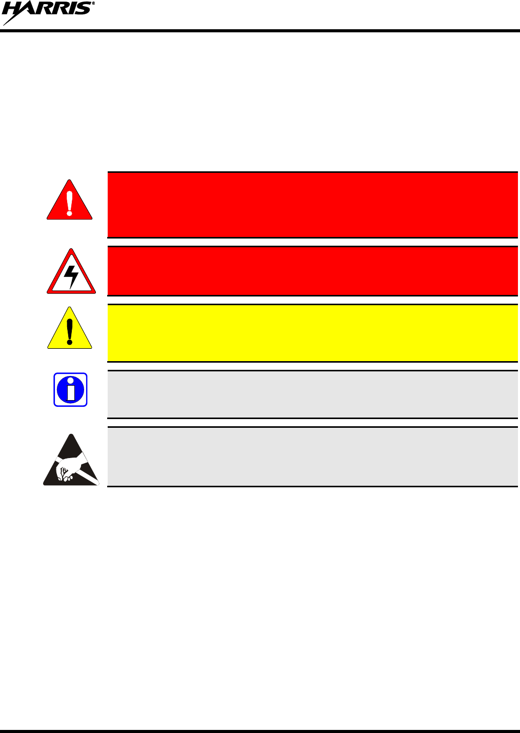
WARNING
The WARNING symbol calls attention to a procedure, practice, or the like, which,
if not correctly performed or adhered to, could result in personal injury. Do not
proceed beyond a WARNING symbol until the conditions identified are fully
understood or met.
The electrical hazard symbol indicates there is an electrical shock hazard present!
CAUTION
The CAUTION symbol calls attention to an operating procedure, practice, or the like,
which, if not performed correctly or adhered to, could result in damage to the
equipment or severely degrade equipment performance.
NOTE
The NOTE symbol calls attention to supplemental information, which may improve
system performance or clarify a process or procedure.
The ESD symbol calls attention to procedures, practices, or the like, which could
expose equipment to the effects of Electro-Static Discharge. Proper precautions must be
taken to prevent ESD when handling circuit boards or modules.
1.2 IMPORTANT SAFETY INFORMATION
The following general safety precautions must be observed during all phases of operation, service, and
repair of this product. Failure to comply with these precautions or with specific warnings elsewhere in
this manual violates safety standards of design, manufacture, and intended use of the product. Harris
assumes no liability for the customer's failure to comply with these standards.
SAVE THIS MANUAL — It contains important safety, installation, and operating instructions.
BEFORE USING THIS EQUIPMENT, please follow and adhere to all warnings, safety and operating
instructions located on the product and in this manual.
GROUNDING AND POWER CONNECTION — To reduce risk of electrical shock and to minimize
exposure to radio frequency (RF) energy, connect the equipment to a properly grounded power source
and site ground point as described in this manual.
MAXIMUM PERMISSIBLE RF EXPOSURE LIMITS —This equipment generates and uses RF
energy. Any changes or modifications to this equipment not expressly approved by Harris may cause
harmful interference and could void the user’s authority to operate the equipment.

14222-5000-3000
6
ELECTROSTATIC DISCHARGE SENSITIVE COMPONENTS — This equipment contains
electronic components that may be damaged by electrostatic discharge. Proper precaution must be
taken when handling circuit modules. As a minimum, grounded wrist straps should be used at all
times when handling circuit modules.
Care should be taken so objects do not fall onto or liquids do not spill into the interior of the
equipment.
DO NOT connect auxiliary equipment not recommended or sold by Harris. To do so may result in
the risk of fire, electric shock or injury to persons.
DO NOT attempt to operate this product in an explosive atmosphere unless it has been specifically
certified for such operation.
To reduce risk of electric shock, isolate the unit and disconnect electrical power before attempting
any maintenance or interior cleaning.
Use only fuses of the correct type, voltage rating and current rating as specified in the parts list.
Failure to do so can result in fire hazard.
Never wear conductive objects such as watches, bracelets, rings, etc., while installing or servicing the
equipment.
1.3 MAXIMUM PERMISSIBLE EXPOSURE LIMITS
DO NOT TRANSMIT with this base station and its antenna when persons are within the MAXIMUM
PERMISSIBLE EXPOSURE (MPE) radius of the radio frequency (RF) antenna. The MPE radius is the
minimum distance from the antenna axis that ALL persons should maintain in order to avoid RF exposure
higher than the allowable MPE level set by the FCC.
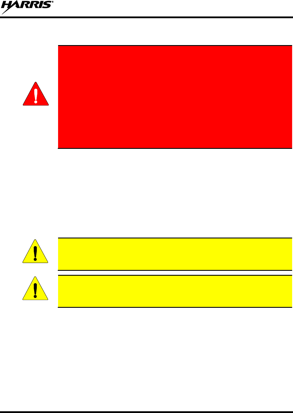
FAILURE TO OBSERVE THESE LIMITS MAY ALLOW ALL PERSONS
WITHIN THE MPE RADIUS TO EXPERIENCE RF RADIATION
ABSORPTION, WHICH EXCEEDS THE FCC MAXIMUM PERMISSIBLE
EXPOSURE (MPE) LIMIT. IT IS THE RESPONSIBILITY OF THE BASE
STATION OPERATOR TO ENSURE THAT THE MAXIMUM PERMISSIBLE
EXPOSURE LIMITS ARE OBSERVED AT ALL TIMES DURING BASE
STATION TRANSMISSION. THE BASE STATION OPERATOR MUST
ENSURE NO BYSTANDERS ARE WITHIN THE MPE RADIUS LIMITS
WHEN THE STATION IS TRANSMITTING.
1.4 DETERMINING MPE RADIUS
THE MAXIMUM PERMISSIBLE EXPOSURE RADIUS is unique for each site and is determined
during site licensing time based on the complete installation environment (i.e. co-location, antenna type,
transmit power level, etc.). Determination of the MPE radius is the responsibility of the installation
licensee. Calculation of the MPE radius is required as part of the site licensing procedure with the FCC.
WARNING
14222-5000-3000
7
1.5 SAFETY TRAINING INFORMATION
THIS BASE STATION GENERATES RADIO FREQUENCY (RF) ELECTRO-
MAGNETIC ENERGY WHEN IT IS TRANSMITTING. THIS BASE STATION IS
DESIGNED FOR AND CLASSIFIED AS “OCCUPATIONAL USE ONLY,”
MEANING IT MUST BE USED ONLY IN THE COURSE OF EMPLOYMENT BY
INDIVIDUALS AWARE OF THE HAZARDS AND THE WAYS TO MINIMIZE
SUCH HAZARDS. THIS BASE STATION IS NOT INTENDED FOR USE BY
THE “GENERAL POPULATION” IN AN UNCONTROLLED ENVIRONMENT.
IT IS THE RESPONSIBILITY OF THE BASE STATION OPERATOR TO
ENSURE THE MAXIMUM PERMISSIBLE EXPOSURE LIMITS ARE
OBSERVED AT ALL TIMES DURING STATION TRANSMISSIONS. THE BASE
STATION OPERATOR IS TO ENSURE THAT NO BYSTANDERS COME
WITHIN THE RADIUS OF THE MAXIMUM PERMISSIBLE EXPOSURE
LIMITS.
When licensed by the FCC, this base station complies with the FCC RF exposure limits when persons are
beyond the MPE radius of the antenna. In addition, the Harris base station’s installation complies with the
following Standards and Guidelines with regard to RF energy and electromagnetic energy levels and
evaluation of such levels for exposure to humans:
FCC OET Bulletin 65 Edition 97-01 Supplement C, Evaluating Compliance with FCC Guidelines for
Human Exposure to Radio Frequency Electromagnetic Fields.
American National Standards Institute (C95.1 – 1992), IEEE Standard for Safety Levels with Respect
to Human Exposure to Radio Frequency Electromagnetic Fields, 3 kHz to 300 GHz.
American National Standards Institute (C95.3 – 1992), IEEE Recommended Practice for the
Measurement of Potentially Hazardous Electromagnetic Fields – RF and Microwave.
To ensure human exposure to RF electromagnetic energy is within the FCC allowable
limits for occupational use, do not operate the base station in a manner that would create
an MPE radius in excess of that allowed by the FCC.
Changes or modifications not expressly approved by Harris could void the user’s authority
to operate the equipment.
1.6 ELECTROMAGNETIC INTERFERENCE
During transmissions, this radio generates RF energy that can possibly cause interference with other
devices or systems. To avoid such interference, turn off the radio in areas where signs are posted to do so.
DO NOT operate the transmitter in areas that are sensitive to electromagnetic radiation such as hospitals,
aircraft, and blasting sites.
WARNING
CAUTION
CAUTION
14222-5000-3000
8
1.7 REGULATORY APPROVALS
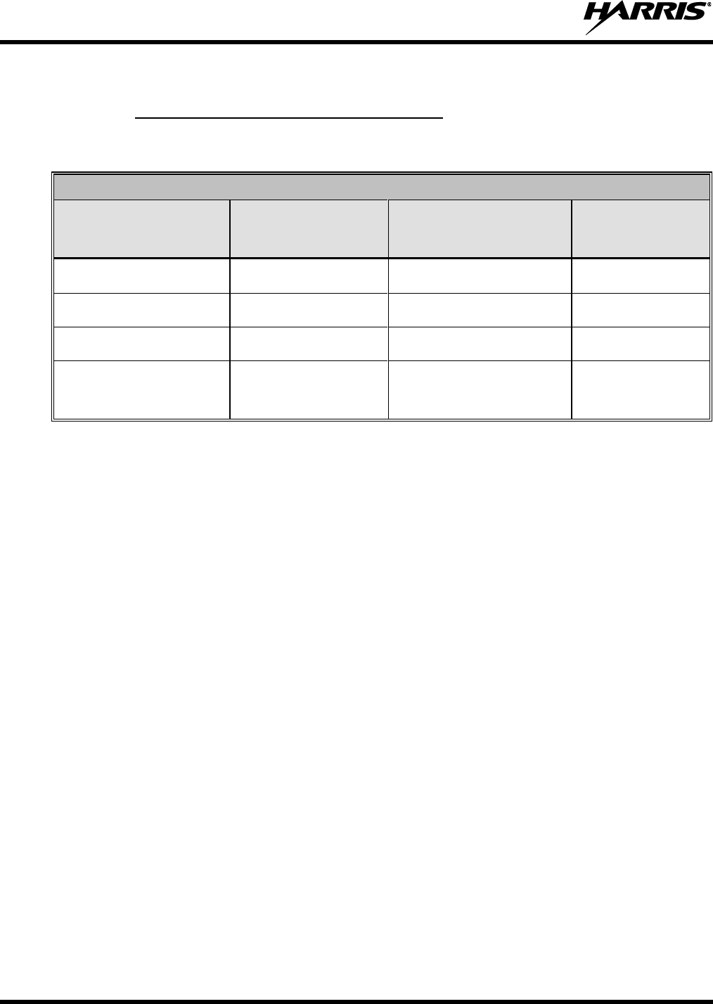
1.7.1 Federal Communications Commission
The transmitting device described within this manual has been tested and found to meet the following
regulatory requirements:
FCC FILING DATA FOR MASTR V BASE STATION
FREQUENCY BAND
(MHz)
POWER OUTPUT
(ADJUSTABLE)
(Watts)
FCC TYPE
ACCEPTANCE NUMBER
APPLICABLE
FCC RULES
136 – 174
1-50
OWDTR-0103E
Part 90
400 – 470
1-50
OWDTR-0102-E
Part 90
450 – 520
1-50
OWDTR-0104-E
Part 90
851 – 870
935 – 941
1-35
1-30
OWDTR-0108-E
Part 90
This receiver associated with this transmitting device has been tested and declared to meet the regulatory
requirements defined in the following sub-sections. Associated FCC labeling may be found on page 2.
1.7.1.1 FCC Compliance
This device complies with Part 15 of the FCC Rules. Operation is subject to the following two conditions:
1. This device may not cause harmful interference, and,
2. This device must accept any interference received, including interference that may cause undesired
operation.
1.7.1.2 Information to the User
This equipment has been tested and found to comply with the limits for a Class A digital device, pursuant
to Part 15 of the FCC Rules. These limits are designed to provide reasonable protection against harmful
interference in a residential installation. This equipment does generate, use, and can radiate radio
frequency energy and, if not installed and used in accordance with the instructions, may cause harmful
interference to radio communications. However, there is no guarantee that interference will not occur in a
particular installation. If this equipment does cause harmful interference to radio or television reception,
which can be determined by turning the equipment off and on, the user is encouraged to try to correct the
interference by one or more of the following measures:
Reorient or relocate the receiving antenna.
Increase the separation between the equipment and receiver.
Connect the equipment into an AC outlet on a circuit different from that which the receiver is
connected.
Consult the dealer or an experienced radio/TV technician for help.
14222-5000-3000
9
1.7.2 Industry Canada
INDUSTRY CANADA FILING DATA FOR MASTR V BASE STATION
FREQUENCY BAND
(MHZ)
INDUSTRY CANADA
CERTIFICATION NUMBER
APPLICABLE INDUSTRY
CANADA RULES
136 – 174
3636B-0103
RSS-119
400 – 470
3636B-0102
RSS-119
450 – 520
3636B-0104
RSS-119
851 – 870
935 – 941
3636B-0108
RSS-119
This Class A digital apparatus complies with Canadian ICES-003.
Cet appareil numérique de la classe A est conforme à la norme NMB-003 du Canada.
WARNING
The installer of this radio equipment must ensure that the antenna is located or
pointed such that it does not emit RF field in excess of Health Canada limits for the
general population; consult Safety Code 6, obtainable from Heath Canada’s website
www.hc-sc.gc.ca/rpb.
L'installateur de cet équipement radio doit garantir que l'antenne est trouvée ou
montrée tel qu'il n'émet pas de champ de RF plus de la Santé les limites du Canada
pour la population générale; consultez le Code 6 de Sécurité, disponible de la Lande
le site Internet du Canada www.hc-sc.gc.ca/rpb.
This device complies with Industry Canada license-exempt RSS standard(s). Operation is subject to the
following two conditions: (1) this device may not cause interference, and (2) this device must accept any
interference, including interference that may cause undesired operation of the device.
Le présent appareil est conforme aux CNR d'Industrie Canada applicables aux appareils radio exempts de
licence. L'exploitation est autorisée aux deux conditions suivantes : (1) l'appareil ne doit pas produire de
brouillage, et (2) l'utilisateur de l'appareil doit accepter tout brouillage radioélectrique subi, même si le
brouillage est susceptible d'en compromettre le fonctionnement.

14222-5000-3000
10
2 SPECIFICATIONS
General
Models: HD-XCV1 (VHF)
HD-XCU1 (UHF-L)
HD-XCU2 (UHF-H)
HD-XC89 (800/900 MHz)
Modulation Type: 4-Level FSK (index: 0.27), TDMA
Transmission Rate: 9.6 kbps
AC Power Input: 100V to 240V (50~60Hz)
Full Load Power Consumption: Per 4-carrier shelf: ≤1200W
Operating Temperature: -30°C to +60°C
Storage Temperature: -40°C to+85°C
Receiver
Frequency Ranges: 136 to 174 MHz (model HD-XCV1)
400 to 470 MHz (model HD-XCU1)
450 to 512 MHz (model HD-XCU2)
806 to 825 MHz and 896 to 902 MHz (model HD-XC89)
Antenna Ports: SMA Female (3 ports/ch., main and 2 diversity)
Static Sensitivity: ≤ -119 dBm at 5% BER (no diversity)
≤ -122 dBm at 5% BER (triple diversity)
≤ -116 dBm at 1% BER
Dynamic Sensitivity: ≤ 112 dBm at 5% BER (no diversity, attenuated by
8km/hr and 100km/hr):
≤ -109 dBm at 5 % BER (triple diversity)
Dynamic Range: ≥ 115 dB
Adjacent Channel Selectivity: ≥ 60 dB
Intermodulation Rejection: ≥ 70 dB
Spurious Emissions: ≤ -57 dBm (9 KHz~1 GHz)
≤ -47 dBm (1 GHz to 12.75 GHz)

14222-5000-3000
11
Transmitter
Frequency Ranges: 136 to 174 MHz (model HD-XCV1)
400 to 470 MHz (model HD-XCU1)
450 to 512 MHz (model HD-XCU2)
851 to 870 MHz and 935 to 941 MHz (model HD-XC89)
Antenna Port: Type-N Female, 50 Ohm
TX Power Output: 1 to 50 Watts per RF Channel (VHF/UHF), ±1.5 dB
1 to 35 Watts per RF Channel (800 MHz), ±1.5 dB
1 to 30 Watts per RF Channel (900 MHz), ±1.5 dB
Modulation Accuracy: ≤ 5.0%
Frequency Offset: ± 1.50 kHz
Intermodulation Attenuation: ≥ 60 dB
Adjacent Channel Power Rejection (ACPR): ≥ 60 dB
Transient Switch ACPR: ≥ 50dB
Spurious Emission: ≤ -36dBm (9 KHz to 1 GHz)
≤ -30dBm (1 GHz to 12.75 GHz)
I/O Ports
GPS Antenna: SMA Female
Port to MSO: E1: BNC-Female/DB9-Female
Ethernet: RJ-45
Local Maintenance Port: RS232/Ethernet
Weights and Dimensions
DEPTH
in (cm)
WIDTH
in (cm)
HEIGHT
in (cm) or RU
Transceiver Shelf (less modules)
19 (48.3)
7RU
Fan Shelf (includes fan drawers)
19 (48.3)
1RU
Extended Interface Board
2.5 (6.5)
11.8 (30)
4.3 (11)
CHU module
16.1 (41)
1..2 (3.0)
10.2 (26)
BSCU module
16.1 (41)
1.9 (4.8)
10.2 (26)
PSU module
16.1 (41)
1.9 (4.8)
10.2 (26)
Notes: For 19” rack mountable equipment, heights may be defined in Rack Units (RU). One (1) RU is equal to
1.75 in. (4.45 cm). For example: 2-RU equals 3.5 in. (8.9 cm), 3-RU equals 5.25 in. (13.3 cm), etc.

14222-5000-3000
12
3 OVERVIEW
The Harris HDT300 is a Tier III-compliant Digital Mobile Radio (DMR) trunked repeater system based
on the European Telecommunications Standards Institute (ETSI) open digital radio Standard TS 102 361
parts 1-4. Sites are currently available in the Land Mobile Radio bands 136 to 174 MHz, 400 to 470
MHz, 450 to 520 MHz, and 800/900 MHz.
A fully configured HDT300 trunked site includes 16-RF channels housed in four (4) transceiver shelves.
Each transceiver shelf (refer to Figure 3-1) can support up to 4-RF channels. Each channel is capable of 1
to 50 Watts RF output power in the VHF and UHF bands, 1 to 35 Watts in the 800 MHz band, and 1 to 30
Watts RF output power in the 900 MHz band. An RF channel operates within a 12.5 kHz channel
spacing using Time Division Multiple Access (TDMA), a 2-timeslot (4-level FSK) constant envelope
modulation scheme.
Four (4) RF shelves may be interfaced together to support up to sixteen RF channels per site. A fully
configured site supports up to 32 timeslots; one timeslot operating as a Control Channel, another
providing dedicated GPS data, and the remaining installed timeslots for voice or data communications.
Figure 3-1: Transceiver Shelf and Fan Assembly (Configured with 4-RF Channels)
14222-5000-3000
13
3.1 HDT300 STATION COMPONENTS
The main hardware components that make up the HDT300 base station include the following:
Transceiver Shelf
Fan Shelf
Channel Unit
Base Station Controller Unit
Power Supply Unit
Extended Interface Board
The transceiver shelf, part number HD-TM1E, houses the station modules, provides interconnection
points to additional transceiver shelves, and to the Extended Interface Board.
The CHannel Unit (CHU) provides a 12.5 kHz RF channel with a 2-timeslot TDMA call capability. Each
transceiver shelf may be populated with up to four (4) CHUs.
The Base Station Controller Unit (BSCU) provides site call and management. Up to two (2) BSCUs may
be installed and setup in a Main BSCU - Backup BSCU configuration.
The Power Supply Unit (PSU) provides conversion from 110/240 VAC to the DC voltages required to
power the station equipment. Each PSU provides DC power to both BSCU modules while PSU1 powers
CHU1 and CHU2 and PSU2 powers only CHU3 and CHU4.
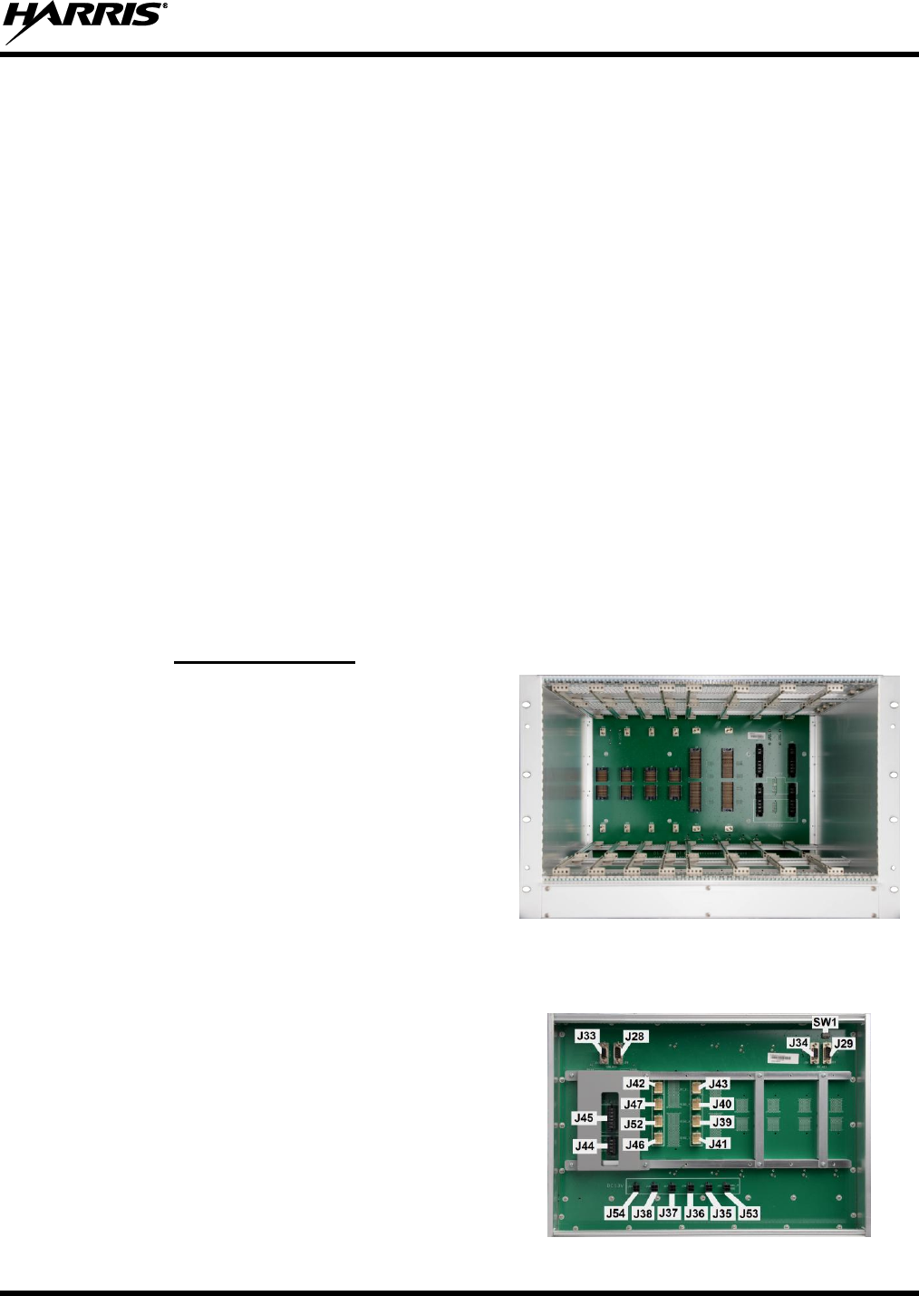
3.1.1 Transceiver Shelf
The transceiver shelf shown in Figure 3-2 is a 19-
inch rack mountable, 7-RU assembly. Each
transceiver shelf can accommodate up to four (4)
CHannel Units (CHU), two (2) Base Station
Controller Units (BSCU), and two (2) Power Supply
Units (PSU).
The transceiver shelf’s Interconnection Backboard
(backplane) provides DC power distribution, signal
distribution among the modules, and signal
distribution to another next transceiver shelf.
Figure 3-2: Transceiver Shelf
3.1.1.1 InterConnect Backboard (ICB)
The ICB (refer to Figure 3-3) is mounted to the rear
of the transceiver shelf and provides power
interconnection, synchronization clock
interconnection, signaling, voice and data
interconnection, monitor interconnection, I/O
interconnection to a second transceiver shelf and the
Extended Interface Board (refer to Section 3.1.6).
All connection points located on the front of the ICB
are for module connectivity. Connection points
located on the rear of the ICB (refer to Figure 3-3)
14222-5000-3000
14
provide connectivity to other transceiver shelves,
programming and test, and the Fan Unit.
Figure 3-3: Connections on ICB (Rear View)
Table 3-1: Transceiver Shelf Rear Panel Connections
CONNECTION
FUNCTION
J44
110/220 VAC Input
J35, J36, J37, J38, J53, J54
13.2 VDC Outputs
J45
-48 VDC Input (Not Supported at this time)
SW1
DIP Switch
J42, J43
Extended Chassis (EC) Interface
J28, J33
CAN-BUS Monitor Interface
J29, J34
RS485 Monitor Interface
J39, J40, J41, J46, J47, J52
EIB Interface
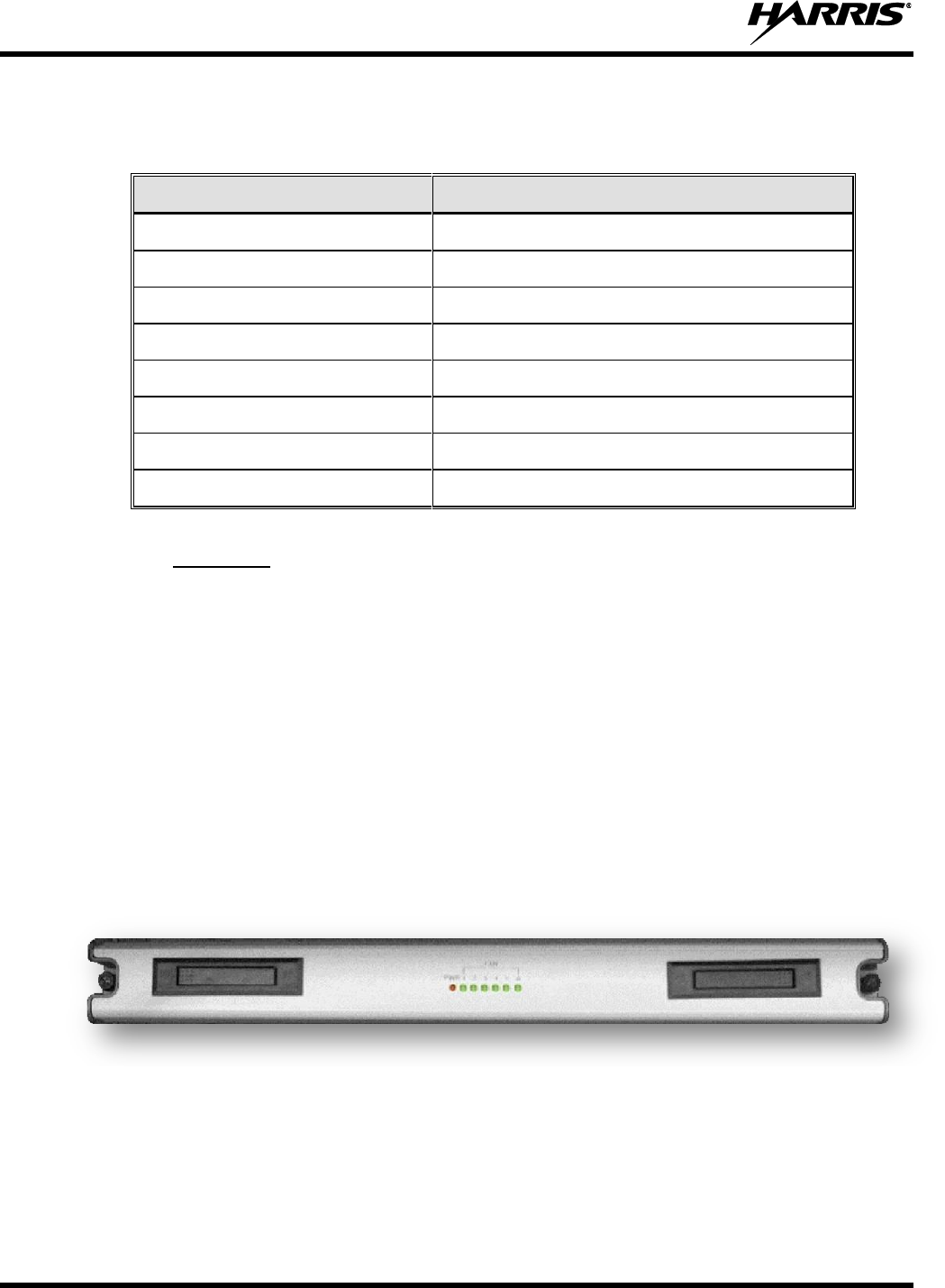
3.1.2 Fan Shelf
The fan shelf, part number HD-BS1C, is a 19” rack mountable 1-RU assembly comprised of a custom
subrack housing six (6) fans, a fan monitor board, backplane board, front panel status LEDs, and built-in
temperature sensors.
The fan monitor board is mounted in the center assembly. DC power, control, and monitor connections
are made at the rear panel. DIP Switch S3 is used to associate the fan shelf to the corresponding
transceiver shelf. The DIP switch settings are described in Section 4.4.1. Section S3-3 is the Least
Significant Bit (LSB) and S3-4 is the Most Significant Bit (MSB). Fan shelves 1 through 4 are assigned
Logic 0 through 3, respectively.
Figure 3-4: Fan Unit (Front Panel)
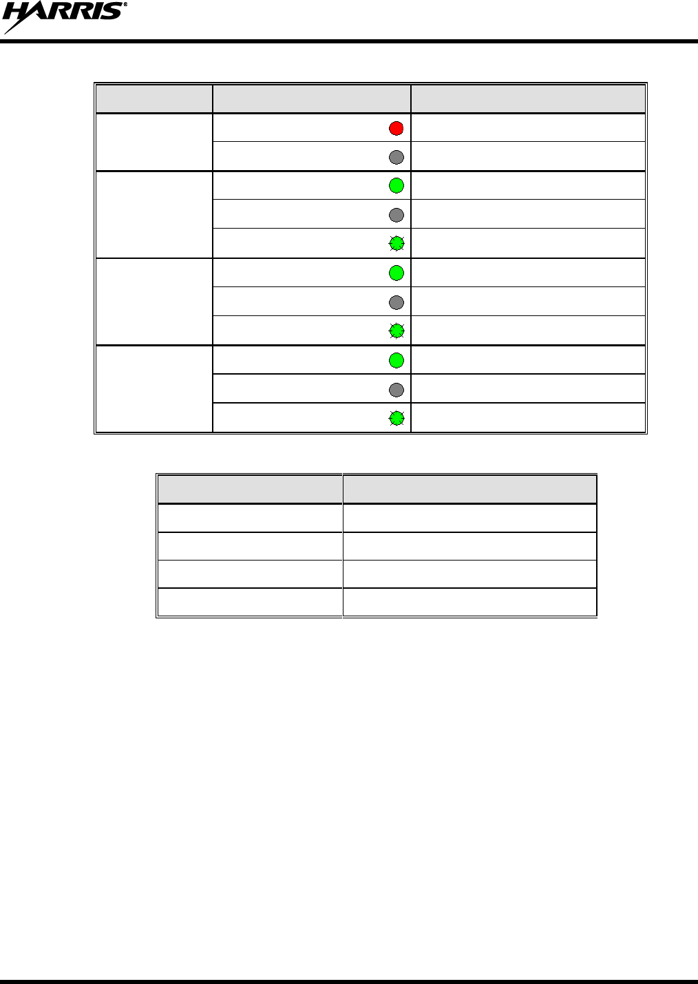
14222-5000-3000
15
Table 3-2: Fan LED Indicators
LABEL
COLOR
DESCRIPTION
POWER
RED
Fan Power On
OFF
Fan Power Failure
1
GREEN
Fan 1 OK
OFF
Fan off or not installed
FLASHING GREEN
Fan 1 Fault
2
GREEN
Fan 2 OK
OFF
Fan off or not installed
FLASHING GREEN
Fan 2 Fault
3
GREEN
Fan 3 OK
OFF
Fan off or not installed
FLASHING GREEN
Fan 3 Fault
CONNECTION
FUNCTION
RS485_M, RS485_F
RS485 Monitor Interface
CAN_M, CAN_F
CAN-BUS Monitor Interface
J21, J22
Power Input
S3
DIP Switch
14222-5000-3000
16
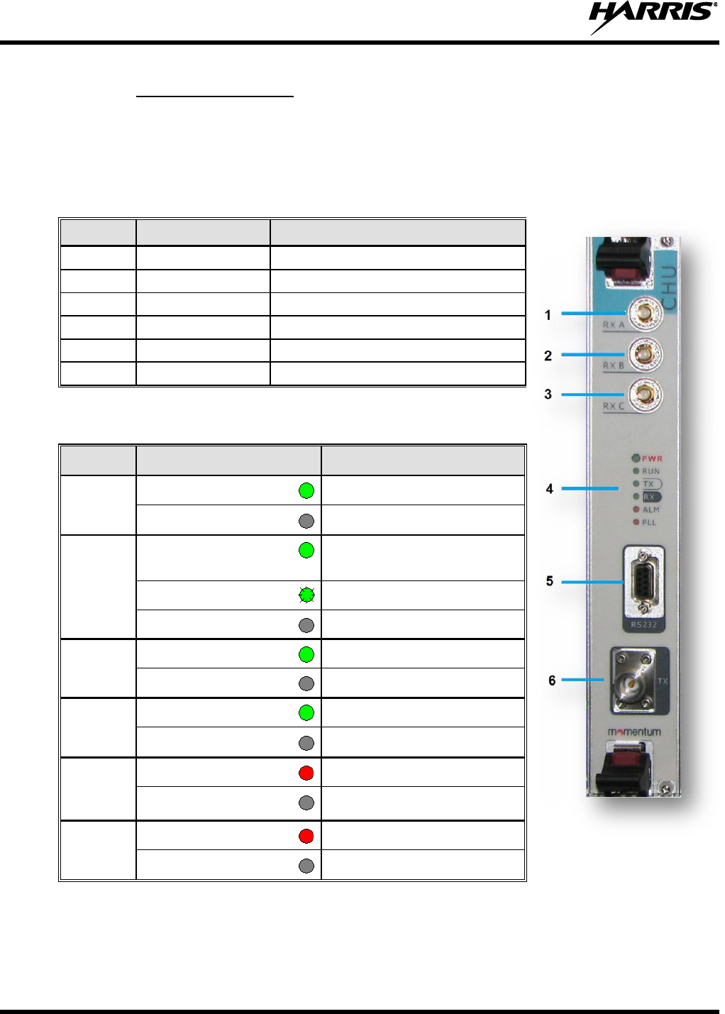
3.1.3 Channel Unit (CHU)
The CHU shown in Figure 3-5 is a microprocessor controller transceiver module with circuits for power
amplification, TX excitation unit, baseband signal processing, and up to three (3) diversity receiver
inputs. The CHU front panel and LED indicators are described in Table 3-3 and Table 3-4. The CHU is
available in the 136-174 MHz band, 400-470 MHz band, 450-520 MHz, and 800/900 MHz band.
Table 3-3: Descriptions on CHU Front Panel
NO.
NAME
DESCRIPTION
1
RXA
Diversity RX Antenna Port
2
RXB
RX Antenna Port
3
RXC
Diversity RX Antenna Port
4
LED Panel
LED Indicators
5
RS232
Test and Configuration
6
TX
TX Antenna Port
Table 3-4: CHU LED Indicators
LABEL
COLOR
DESCRIPTION
PWR
GREEN
PSU Active, No Faults
OFF
No Power
RUN
GREEN
BSCU Communications
Normal
FLASHING GREEN
CHU is Starting
OFF
CHU is Repeating
TX
GREEN
CHU is Allocating Channel
OFF
TX Channel is Free
RX
GREEN
Carrier Signal Present
OFF
RX Channel is Free
ALM
RED
CHU Fault
OFF
No CHU Fault
PLL
RED
PLL Unlocked
OFF
PLL Active, No Faults
Figure 3-5:
CHU Front Panel
14222-5000-3000
17
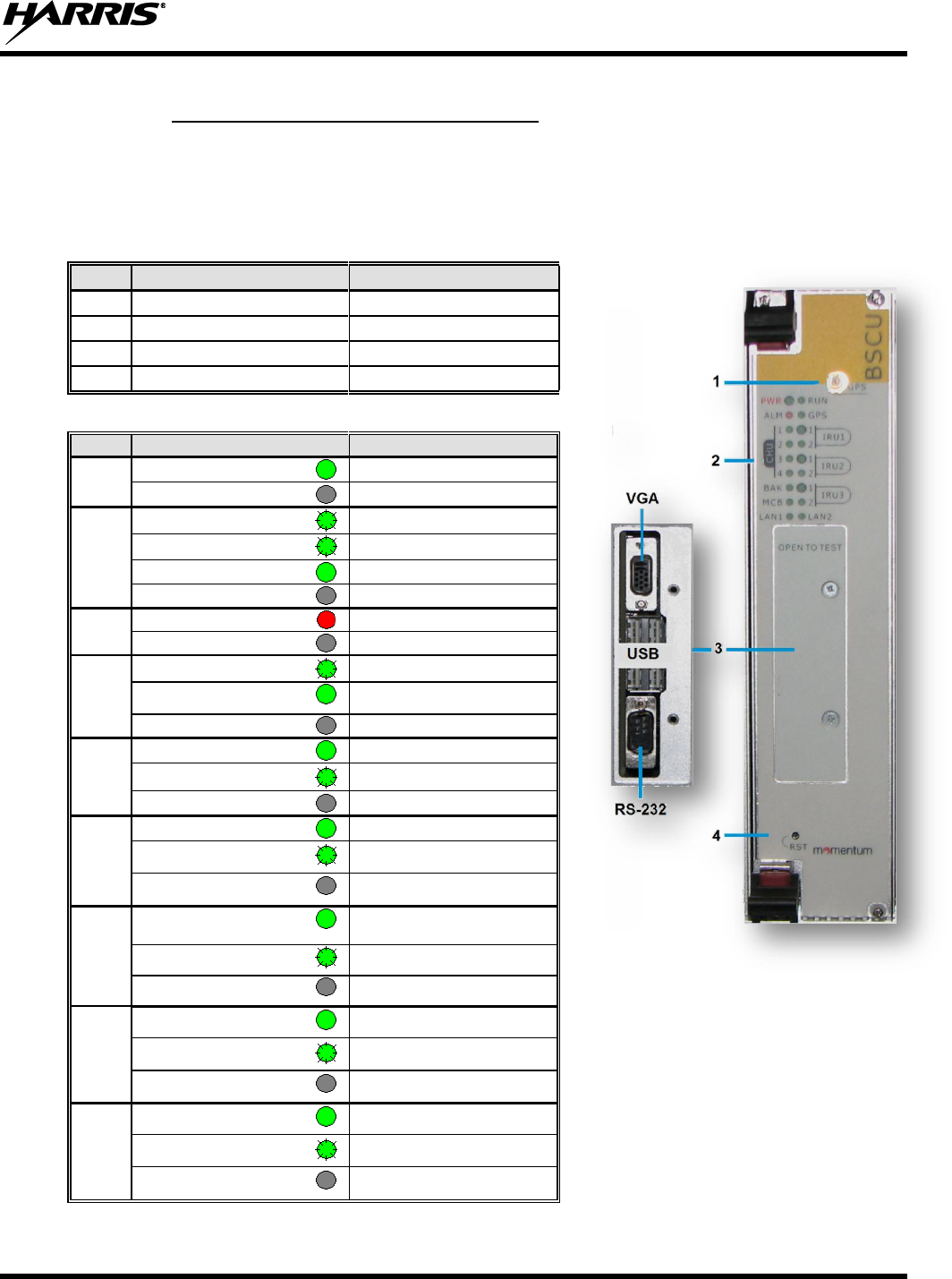
3.1.4 Base Station Controller Unit (BSCU)
The BSCU, part number HD-BS1A, manages the overall operation of the site; assigning channels,
timeslots, and interfacing with the LAN, Ethernet, and other devices. Each transceiver shelf may be
equipped with a redundant MSCU. The front panel features are illustrated in Figure 3-6 and the LED
indicators are described in Table 3-6.
Table 3-5: BSCU Front Panel Description
NO.
NAME
DESCRIPTION
1
GPS
GPS Antenna Port
2
LED Panel
LED Indicators
3
OPEN TO TEST
VGA, USB, and RS232
4
RST
BSCU Reset
Table 3-6: BSCU LED Indicators
LABEL
COLOR
DESCRIPTION
PWR
GREEN
Power On
OFF
Power Failure
RUN
FAST FLASH GREEN
BSCU Main Mode
SLOW FLASH GREEN
BSCU Backup Mode
GREEN
BSCU Starting
OFF
BSCU not working
ALM
RED
BSCU Fault
OFF
No BSCU faults
GPS
FLASHING GREEN
Disabled via Local Command
GREEN
Disabled via GPS Rcvr
OFF
Enabled, Active
CHU1
-4
GREEN
BSCU-CHU Link Active
FLASHING GREEN
BSCU-CHU Data Transfer
OFF
BSCU-CHU No Comms
IRU1
3
GREEN
BSCU-IRU Link Active
FLASHING GREEN
BSCU-IRU Data Transfer
OFF
BSCU-IRU No Comms
BAK
GREEN
BSCU Main-BSCU Backup
Link Active
FLASHING GREEN
BSCU-BSCU Data Transfer
OFF
BSCU-BSCU No Comms
MCB
GREEN
BSCU-MCB Link Active
FLASHING GREEN
BSCU-MCB Data Transfer
OFF
BSCU-MCB No Comms
LAN1
LAN2
GREEN
BSCU-LAN Link Active
FLASHING GREEN
BSCU-LAN Data Transfer
OFF
BSCU-LAN No Comms
Figure 3-6:
BSCU Front Panel
14222-5000-3000
18
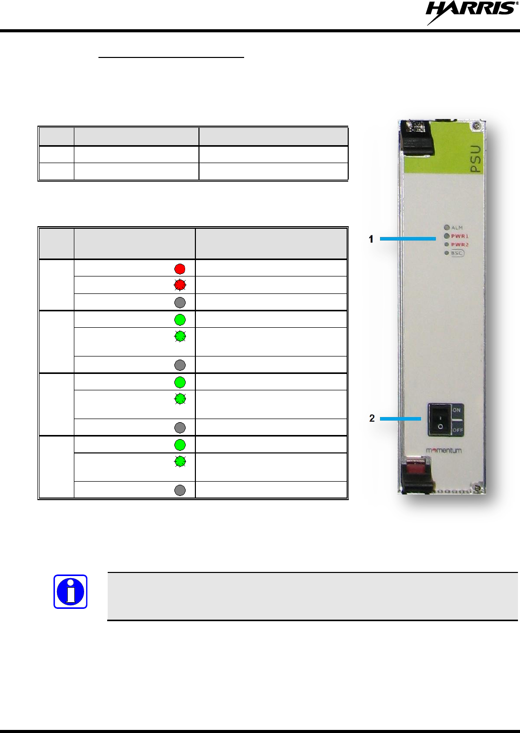
3.1.5 Power Supply Unit (PSU)
The PSU, part number HD-BS1B, consists of power monitoring board, power module, and LED panel.
The front panel of the PSU is illustrated in Figure 3-7. The PSU indicators are described in Table 3-8.
Table 3-7: PSU Front Panel Features
NO.
NAME
DESCRIPTION
1
LED Panel
LED Indicators
2
ON/OFF
Power Switch
Table 3-8: LED Indicators on PSU Front Panel
LABE
L
COLOR
DESCRIPTION
ALM
RED
Major Alarm
FLASHING RED
Minor Alarm
OFF
No Faults
PWR
1
GREEN
Path 1 Outputs Active
FLASHING
GREEN
Path 1 Outputs HVCC or
LVCC Alarm
OFF
Path 1, No Output Voltage
PWR
2
GREEN
Path 2 Outputs Active
FLASHING
GREEN
Path 2 Outputs HVCC or
LVCC Alarm
OFF
Path 2, No Output Voltage
BSC
GREEN
BSC Output Voltage Normal
FLASHING
GREEN
BSC Over/Under Voltage
Alarm
OFF
BSC Failure
Figure 3-7:
PSU Front Panel
NOTE
The power module has two-path outputs including HVCC and LVCC.
14222-5000-3000
19
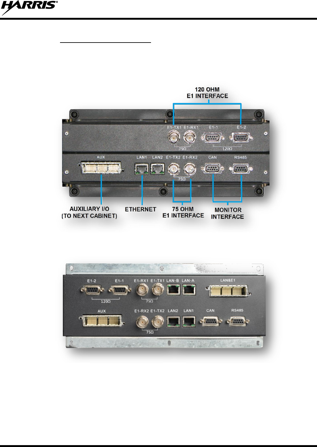
3.1.6 Extended Interface Board
The Extended Interface Board (EIB), part number HD-TM1F, shown in Figure 3-8 and Figure 3-9
provides E1, Ethernet, Monitor, and Auxiliary Interface connections. The EIB is required to provide
connectivity to an IP network or transceiver shelf 3 and 4. Figure 3-8 shows the side of the assembly
where external connections are made to the station. Figure 3-9 shows the
Figure 3-8: Extended Interface Board (External Connections View)
Figure 3-9: Extended Interface Board (Internal Connections View)
14222-5000-3000
20
4 INSTALLATION
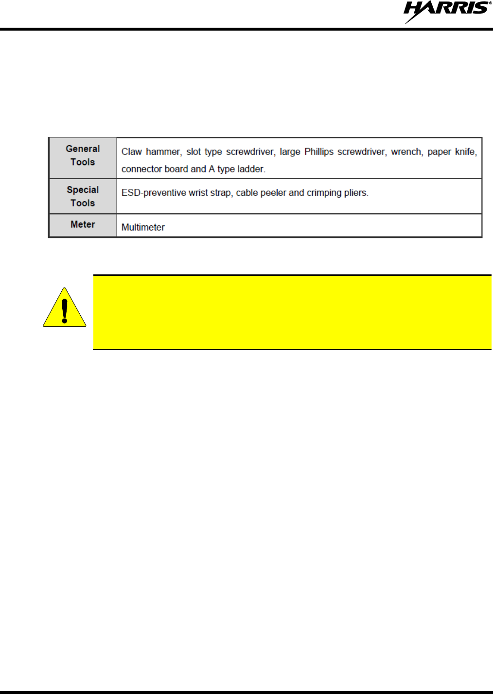
4.1 TOOLS
The following tools are required for installation:
Table 4-1: Tools and Meter
4.2 UNPACKING AND INSPECTION
After removal from the shipping container, examine the components and installation items
for broken, damaged, loose, or missing parts. If any are noted, contact Harris
representative immediately to discuss and arrange for the return of the equipment for
replacement. Any unauthorized attempts to repair or modify this equipment will void the
warranty and could create a safety hazard.
Carefully unpack the equipment and examine each item. If there is any damage to the equipment, contact
the carrier immediately and have their representative verify the damage. If you fail to report the shipping
damage immediately, you may forfeit any claim against the carrier.
When unpacking the equipment, check the contents against the packing list. Contact your Harris
representative and the carrier if any discrepancies are noted. Carefully open each rack and inspect the
contents to ensure the enclosed equipment has not been damaged during delivery. If damage has
occurred, note details of the damage and, if necessary, contact the carrier immediately and have their
representative verify the damage. Contact your Harris representative if the damage is such that
installation cannot proceed.
4.3 GROUNDING THE EQUIPMENT
Ensure all equipment and facilities meet the requirements for grounding and lightning protection. Site
Grounding and Lightning Protection Guidelines manual AE/LZT 123 4618/1 provides proper grounding
procedures. These guidelines must be observed in order to protect the equipment and service personnel
from lightning and other sources of electrical surges.
Each 19” rack mounted assembly typically has a grounding point identified on the assembly. Use this
location to ground each sub-assembly to the cabinet or rack ground bus bar. Properly ground the bus bar
to the building or room’s ground system.
Transmission lines, telephone equipment, HVAC equipment, door frames, and any other metallic objects
located in and around the facility must be properly grounded per the site grounding manual.
CAUTION
14222-5000-3000
21
4.3.1 Surge Protection Devices (SPDs)
All RF transmission lines and surge protection devices (SPDs) should be grounded in accordance with
procedures presented in Site Grounding and Lightning Protection Guidelines manual
AE/LZT 123 4618/1. PolyPhaser® or similar SPD devices are required for all RF, phone, or on-site
control lines entering the building from external sources. For GPS antenna installation, Harris
recommend using a GPS surge arrestor, part number HD-TM1M-02, inline with each GPS antenna.
4.4 INSTALLING THE EQUIPMENT
The HDT300 is designed to be installed in a 19-inch rack or cabinet. A ground bus bar should be utilized
to minimize ground loops and the potential for electrical surges, such as lightning, from traveling through
the equipment while dissipating to the grounding system.
Carefully pre-plan the rackup, locating the fan shelf directly under each transceiver shelf, and ensuring
adequate air flow above and below the rackup. It is also recommended to install the modules after the
shelf is fully installed, the grounding bus bar system is fully installed and the bus bar is properly grounded
to the site grounding system.
Additionally, it may be beneficial to begin installing equipment from the bottom of the rack or cabinet
and building up the rail. It is recommended to follow the steps shown in the following sub-sections when
installing equipment.
The first transceiver and fan shelf installation supports the first four (4) RF channels. For sites with five
(5) or more RF channels, multiple transceiver and fan shelf installations are preformed. Typically, two
(2) individual rackups consisting of a transceiver shelf, fan shelf, and EIB may be installed per the
average tall rack or cabinet (supporting RF channels 1 through 8). For RF channels 9 through 16, a
second cabinet or rack is typically required.
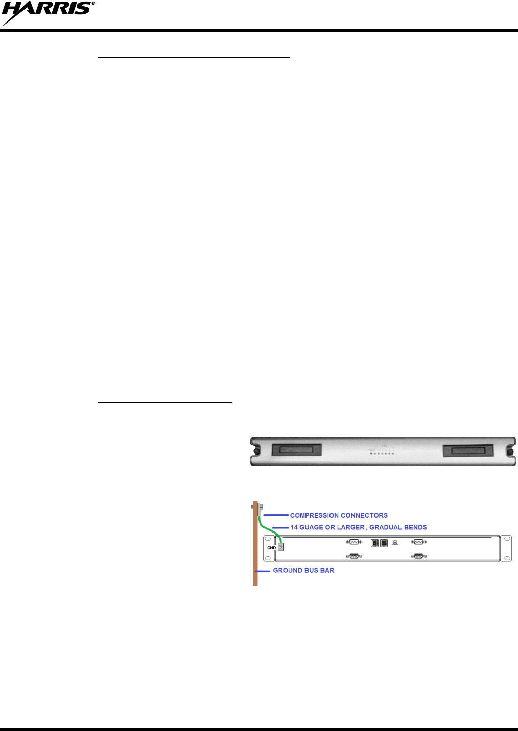
4.4.1 Installing the Fan Shelf
1. Determine the installation location
along the rails and if required, install
screw clips in the two (2) screw
locations.
2. Install screws in the two (2) mounting
locations.
3. Install a ground wire from the fan shelf
rear panel to the ground bus bar.
For best performance, equipment
ground wires should be constructed
using UL-listed compression-type
connectors and 14-gauge or larger
stranded ground wire. Always use
gradual bends in the wire (no sharp
angles).
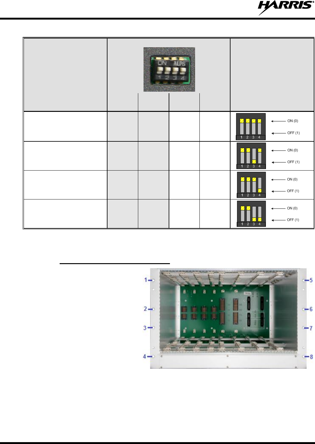
4. Set DIP Switch S3 for the proper shelf
identity per the following instructions:
DIP Switch S3 is used to associate the fan shelf to the corresponding transceiver shelf. The DIP switch
settings are described in Table 4-2. Section S3-3 is the Least Significant Bit (LSB) and S3-4 is the Most
Significant Bit (MSB). Fan shelves 1 through 4 are assigned Logic 0 through 3, respectively.
14222-5000-3000
22
Table 4-2: Fan DIP Switch Settings
Shown set for Shelf 1
FAN SHELF #
SW1-1
SW1-2
SW1-3
(LSB)
SW1-4
(MSB)
DIP SWITCH S3
CONFIGURATION
Fan Shelf 1
(RF Channels 1 through 4)
NA
NA
ON
ON
Fan Shelf 2
(RF Channels 5 through 8)
NA
NA
OFF
ON
Fan Shelf 3
(RF Channels 9 through 12)
NA
NA
ON
OFF
Fan Shelf 4
(RF Channels 13 through16)
NA
NA
OFF
OFF
* N/A = Not applicable (not used).
4.4.2 Installing the Transceiver Shelf
1. Install the transceiver shelf just
above the associated fan shelf. If
required, install screw clips in the
eight (8) corresponding screw
locations along the rails.
2. Install screws in all eight (8)
mounting locations.
14222-5000-3000
23
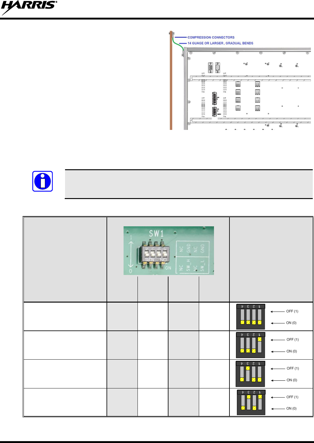
3. Install a ground wire from the transceiver
shelf to the ground bus bar.
For best performance, equipment ground
wires should be constructed using UL-listed
compression-type connectors and 14-gauge
or larger stranded ground wire. Always use
gradual bends in the wire (no sharp angles).
4. Set DIP Switch SW1 for the proper shelf
identity per the following instructions:
DIP Switch SW1 is used to identify the transceiver shelf to the BSCU. The DIP switch settings are
described in Table 4-3. Transceiver Shelves 1 through 4 are assigned Logic 0 through 3, respectively,
using SW1-1 and SW1-3. Section SW1-1 is the Least Significant Bit (LSB) and SW1-3 the Most
Significant Bit (MSB). . Sections SW1-2 and SW1-4 are not used.
NOTE
The DIP switch is mounted in an inverted position. SW1-1 is actually the right-most
position as viewed while facing the rear panel.
Table 4-3: Interconnection Board DIP Switch Configuration
Shown set for Shelf 1
TRANSCEIVER
SHELF #
SW1-4
(Not
Used)
SW1-3
(MSB)
SW1-2
(Not
Used)
SW1-1
(LSB)
DIP SWITCH SW1
CONFIGURATION
Transceiver Shelf 1
(RF Channels 1 through 4)
NA
ON
NA
ON
Transceiver Shelf 2
(RF Channels 5 through 8)
NA
ON
NA
OFF
Transceiver Shelf 3
(RF Channels 9 through 12)
NA
OFF
NA
ON
Transceiver Shelf 4
(RF Channels 13 through16)
NA
OFF
NA
OFF
* N/A = Not applicable (not used).
14222-5000-3000
24
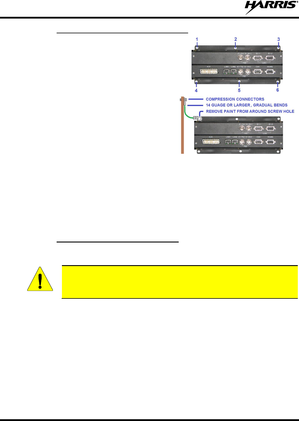
4.4.3 Installing the Extended Interface Board
1. Determine the installation location and install using
the six (6) screw locations.
2. Install a ground wire from the EIB panel to the
ground bus bar.
If possible, install the ground lug to the rear of the
EIB panel where the surface is not painted.
Alternately, remove paint from around one hole on
the front of the panel’s mounting flange.
For best performance, equipment ground wires
should be constructed using UL-listed compression-
type connectors and 14-gauge or larger stranded
ground wire. Always use gradual bends in the wire
(no sharp angles).
4.5 CABLE CONNECTIONS
Figure 4-1 represents a 4-channel rackup. Up to four (4) rackups similar to that shown in Figure 4-1 may
be connected for a maximum of 16 RF channels at one site. Backplane connections at each of the four
rackups are similar with only cable additions for interconnecting the multiple rackups.
4.5.1 Initial Backplane Cable Connections
Before installing cables, the equipment shelves and grounding system should be installed as per the
previous sub-sections.
CAUTION
Make sure all AC and DC power input is Off or disabled before making connections to
the equipment.
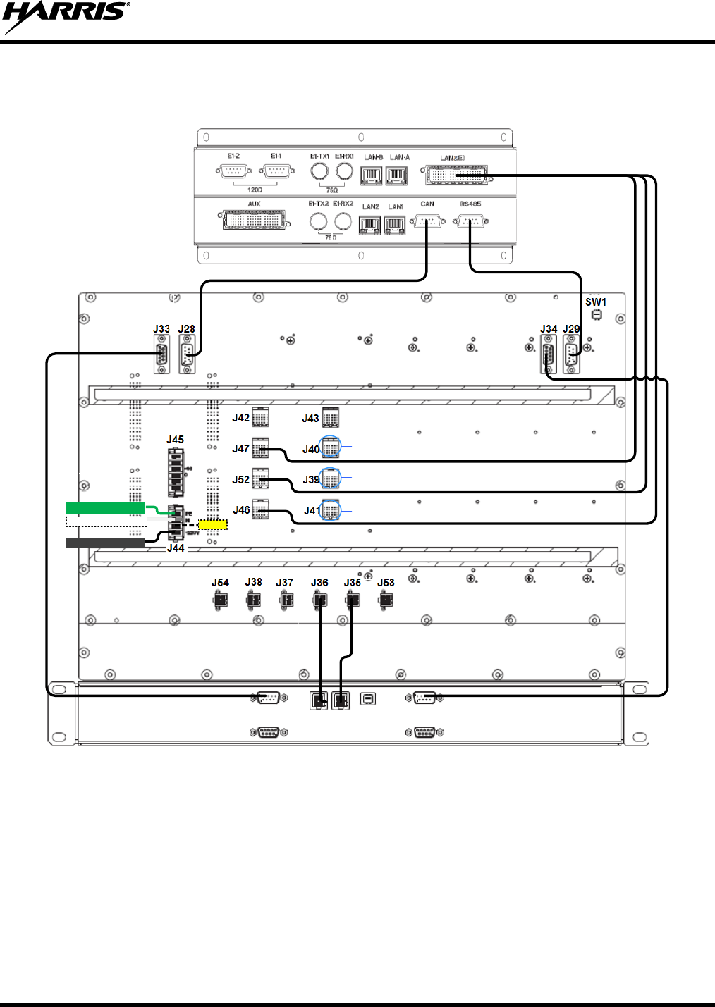
1. Make the following backplane cable connections as shown on Figure 4-1.
a. Cable from EIB LAN&E1 connection to the transceiver shelf J46, J47, and J52 connections.
b. Cable from EIB’s CAN connection to the transceiver shelf J28.
c. Cable from EIB’s RS485 connection to the fan shelf J29.
d. Cable from transceiver shelf J34 to the fan shelf RS485_M.
e. Cable from transceiver shelf J35 to the fan shelf DC input.
f. Cable from transceiver shelf J36 to the fan shelf DC input.
g. Cable from transceiver shelf J33 to the fan shelf CAN_M.
h. Customer supplied AC power cable Chassis GND wire to transceiver shelf J44-PE.
i. Customer supplied AC power cable Neutral wire to transceiver shelf J44-N.
j. Customer supplied AC power cable Leg 1 (L1) wire to transceiver shelf J44-220V.
14222-5000-3000
25
1B
1C
1A
2A
2B
2C
GND
NEUTRAL
L1 (110/220VAC)
N/C
EIB
TRANSCEIVER SHELF
FAN SHELF
CAN_M RS485_M
Figure 4-1: HDT300 Backplane Wiring Diagram
14222-5000-3000
26
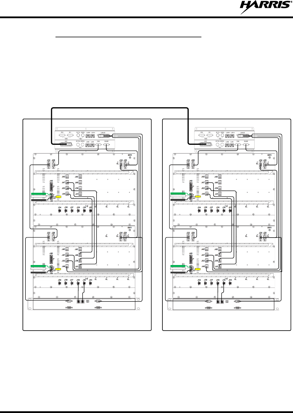
4.5.2 Multi-Shelf Multi-Cabinet Cable Connections
Figure 4-1 represents a 4-channel rackup. Up to four (4) rackups similar to that shown in Figure 4-1 may
be connected for a maximum of 16 RF channels at one site. Backplane connections at each of the four
rackups are similar with only cable additions for interconnecting the multiple rackups.
Typically, two (2) individual rackups of a transceiver shelf, fan shelf, and EIB may be installed per the
average tall rack or cabinet (supporting RF channels 1 through 8). For RF channels 9 through 16, a
second cabinet or rack is typically required.
110/240 VAC
INPUT
CHANNELS 1-4
1B
1C
1A
2A
2B
2C
1B
1C
1A
2A
2B
2C
CHANNELS 5-8
FAN
L1
110/240 VAC
INPUT
CHANNELS 9-12
1B
1C
1A
2A
2B
2C
110/240 VAC
INPUT
1B
1C
1A
2A
2B
2C
CHANNELS 13-16
FAN
GND
NEUTRAL
L1 (110/220VAC)
N/C
GND
NEUTRAL
L1 (110/220VAC)
N/C
GND
NEUTRAL
L1 (110/220VAC)
N/C
GND
NEUTRAL
L1 (110/220VAC)
N/C
Figure 4-2: HDT300 Multi-Shelf – Multi Cabinet Configuration
14222-5000-3000
27
4.6 INSTALLING MODULES
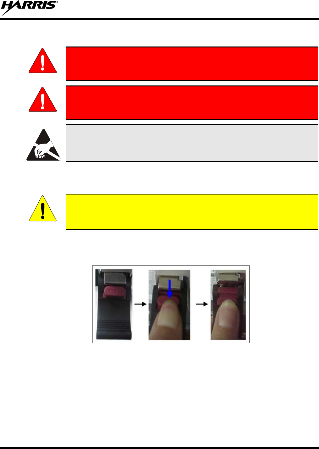
WARNING
Some components of the power system carry hazardous voltage in operation.
Direct or indirect contact through moist objects with these components will result
in fatal injury.
WARNING
Make sure all AC input power is turned off to the equipment and the power switch
on each PSU is set to the Off position before installing the PSU modules.
The ESD symbol calls attention to procedures, practices, or the like, which could
expose equipment to the effects of Electro-Static Discharge. Proper precautions must be
taken to prevent ESD when handling circuit boards or modules.
Cabinets and racks may be pre-racked and tested in a shop or staging environment; however, the
Momentum modules and fan drawers must be removed from the shelves before transporting the rackup.
This will prevent damage to the shelf units and modules.
CAUTION
DO NOT transport a pre-assembled rackup without first removing the modules and fans
from the shelf assemblies. The weight of the installed modules and fan drawers can
potentially damage the shelf assemblies during transport.
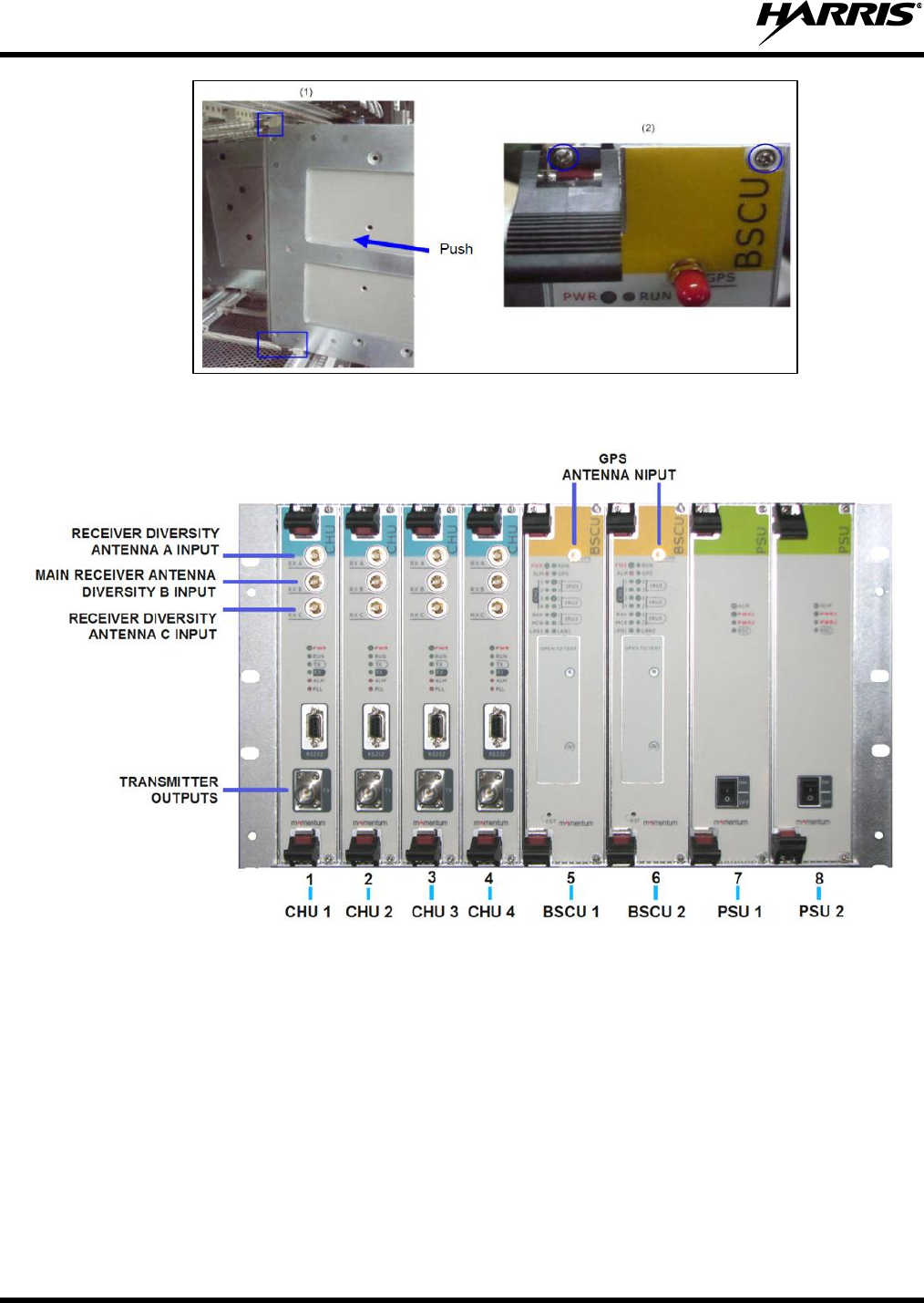
1. Install the modules into the shelf slots as shown in Figure 4-5 per the following instructions:
a. Loosen the two ejectors by pressing the red locking mechanism to release the ejectors (refer to
Figure 4-3).
Figure 4-3: Loosening the Ejector
b. Slide the BSCU along the guide rails smoothly as shown in Figure 4-4.
c. Re-latch the ejectors after the module is fully inserted into the card cage.
d. Tighten the screw located within each ejector.
e. Tighten the screw on the top and bottom-right corners of each module as shown in Figure 4-4.
14222-5000-3000
28
Figure 4-4: Installing the BSCU
Figure 4-5: Module Placement and Front Panel Cable Connections

14222-5000-3000
29
4.7 FRONT PANEL CONNECTIONS
4.7.1 RF Antenna Connections
The CHU modules include RF connections for the RX and TX antennas. Cables for each connection are
customer supplied and must be high grade, low loss cables. Cable lengths should be kept as short as
possible to minimize cable loss; however, it may be desirable to use the same type cable for each similar
connection and similar lengths to minimize imbalances between channels during operation.
4.7.2 GPS Receiver Antenna Connections
The GPS receiver input on each BSCU module is a non-powered antenna connection. A GPS antenna,
part number HD-TM1M-01, is available and may be ordered through the Harris representative for the
HDT300 system. A GPS antenna surge arrestor, part number HD-TM1M-02, should be installed along
with each GPS antenna. If both BSCU modules are installed, the GPS antenna inputs may be connected
to separate GPS antennas (desired method, antennas not supplied) or connected to a common GPS
antenna using a customer supplied power splitter/multicoupler.
Follow all manufacturers’ instructions for installing and connecting the GPS antenna to the BSCU. Cable
lengths should be kept as short as possible to minimize cable loss. Any recommended maximum antenna
cable lengths should be observed. For installations requiring longer than recommended cable lengths, an
amplified antenna system is recommended or use an inline RF antenna amplifier designed specifically for
GPS antenna systems.
4.7.3 Additional front panel connections
Additional front panel connections for RS232 and other ports are used during setup and configuration and
out of the scope of this manual.
14222-5000-3000
30
5 POST-INSTALLATION INSPECTION
Verify the following before proceeding with power-up of the system:
a. The cabinet or rack has been installed and grounded per the Site Grounding and Lightning Protection
Guidelines Manual, AE/LZT 123 4618/1.
b. All safety ground connections are:
i. Properly crimped.
ii. Connected to the proper connection points on the equipment.
iii. Connected to the ground bus bar using gradual bends in an upward fashion.
iv. Nut and/or bolts securing the ground lugs are sufficiently tightened.
c. All AC power cables have been labeled and installed per Section 4.5.
d. All rear panel control cable connections have been labeled and installed per Section 4.5
e. All modules have been installed per Section 4.6.
f. All front panel power switches on the PSU units have been set to the Off position.
g. All front panel RF antenna connections are labeled and installed per Section 4.7.
h. Verify all receive and transmit antenna ports are connected to 50 ohm load resistors of sufficient
power rating.
CAUTION
To prevent unintentional or malicious interference to other radio systems, the receive
and transmit antenna ports of all new installations should first be connected to 50 ohm
load resistors of sufficient power rating until the system is programmed to the proper
operating frequencies and ready to be deployed.
14222-5000-3000
31
6 POWER-UP
1. Transmitter and receiver antenna ports should be connected to 50 ohm load resistors of sufficient
power rating until the system is programmed to the proper operating frequencies and ready to be
deployed.
2. Verify the post installation inspection in Section 5 is complete.
3. Apply power to the equipment from the AC mains breaker or switch.
4. Set all power switches on the PSU modules to the On position.
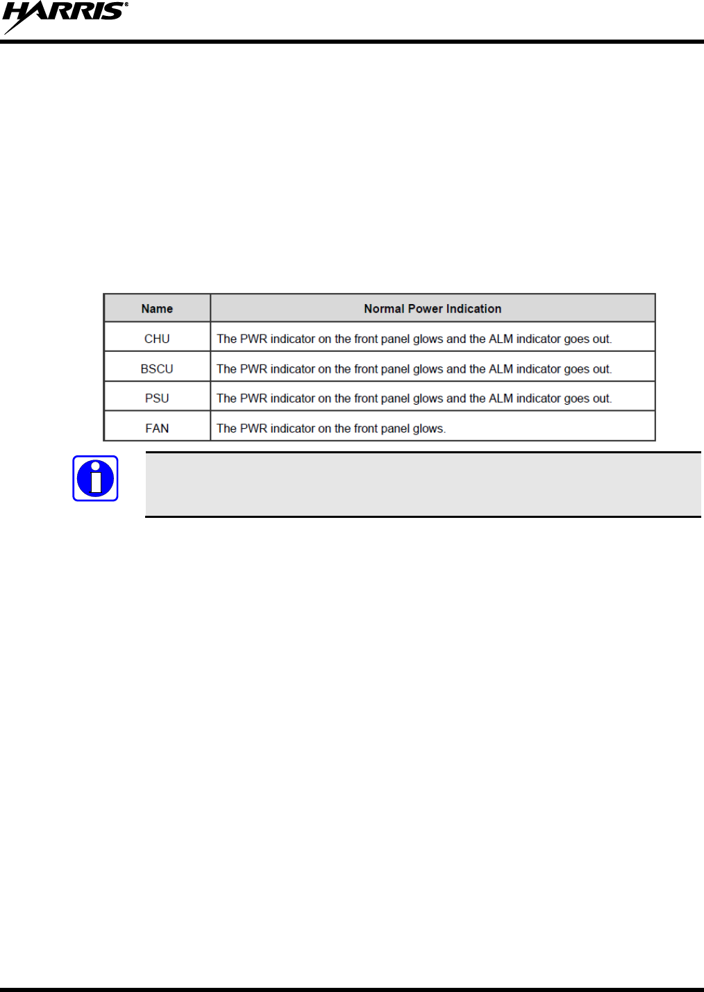
5. Verify all modules power up properly with no alarms (refer to Table 6-1).
Table 6-1: Power and Alarm Indicator Checklist
NOTE
If any LED indicators indicate a failure, power down the cabinet, reseat the modules,
and re-power the cabinet. If the issue persists, contact you dealer.

14222-5000-3000
32
7 CUSTOMER RESOURCES
7.1 REPLACEMENT PARTS
To order replacement parts, contact the Customer Care center at:
http://www.pspc.harris.com/CustomerService
Or use one of the following phone numbers, fax numbers, or email addresses:
United States:
Phone Number: 1-800-368-3277
Fax Number: 1-321-409-4393 (U.S. Only)
E-mail: PSPC_CustomerFocus@harris.com
International:
Phone Number: 434-455-6403
Fax Number: 321-409-4394
E-mail: PSPC_InternationalCustomerFocus@harris.com
7.2 TECHNICAL ASSISTANCE
If any of the radio equipment requires repair, or if there are questions or concerns about the installation of
this equipment, contact the Harris Technical Assistance Center (TAC) using the following telephone
numbers or e-mail address:
United States and Canada: 1-800-528-7711 (toll free)
International: 1-434-385-2400
Fax: 1-434-455-6712
E-mail: PSPC_tac@harris.com
7.3 TECH-LINK
For more information about this and other Harris PSPC products, check out our Tech-Link service at:
https://premier.pspc.harris.com/
Tech-Link is a one stop link to Technical Documentation (downloadable PDFs) - Software Revisions -
Feature Encryption - pictorials of parts and accessories - and other information pertaining to our products.
Information that will enhance your service efforts -- 24 hours a day, 7 days a week.

14222-5000-3000
33
This page intentionally left blank.

Public Safety and Professional Communications | www.pspc.harris.com
221 Jefferson Ridge Parkway | Lynchburg, VA USA 24501 | 1-800-528-7711