HARRIS TR-0109-E XG-25P UHF-L User Manual Operations Manual
HARRIS CORPORATION XG-25P UHF-L Operations Manual
UserManual.wiki
>
HARRIS
>
TR-0109-E User Manual
>
Operations Manual
Contents
1.
Operations Manual
2.
Safety Manual
3.
Operational Manual
Operations Manual
Navigation menu
Upload a User Manual
Namespaces
Wiki Guide
HTML
PDF
Info
Views
User Manual
Discussion / Help
Navigation
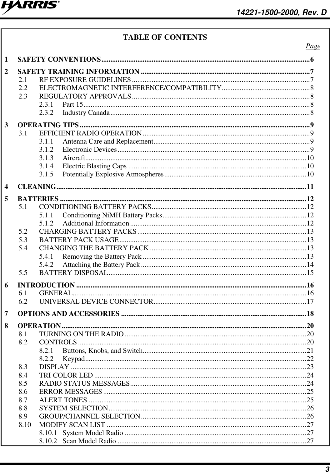
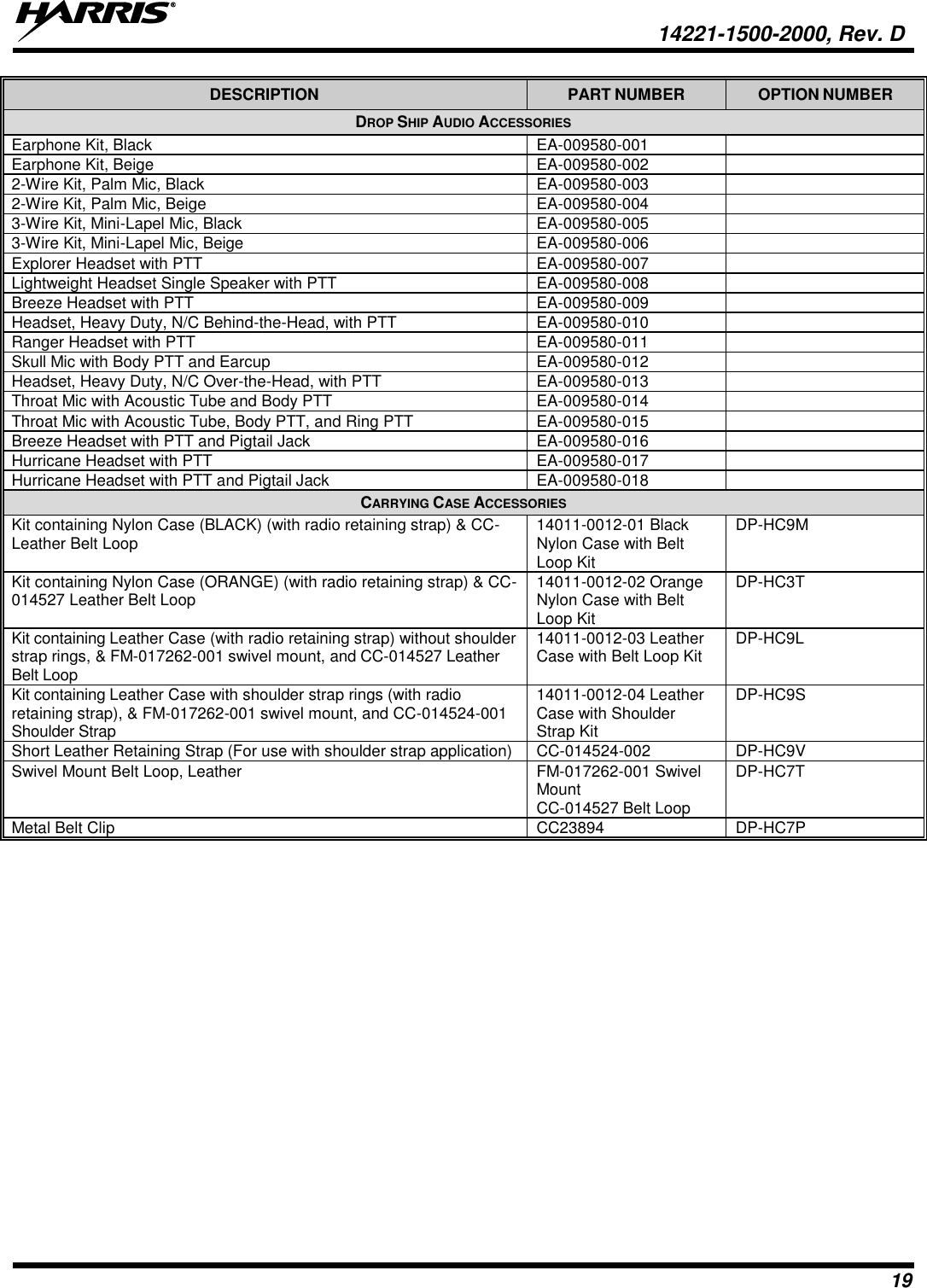
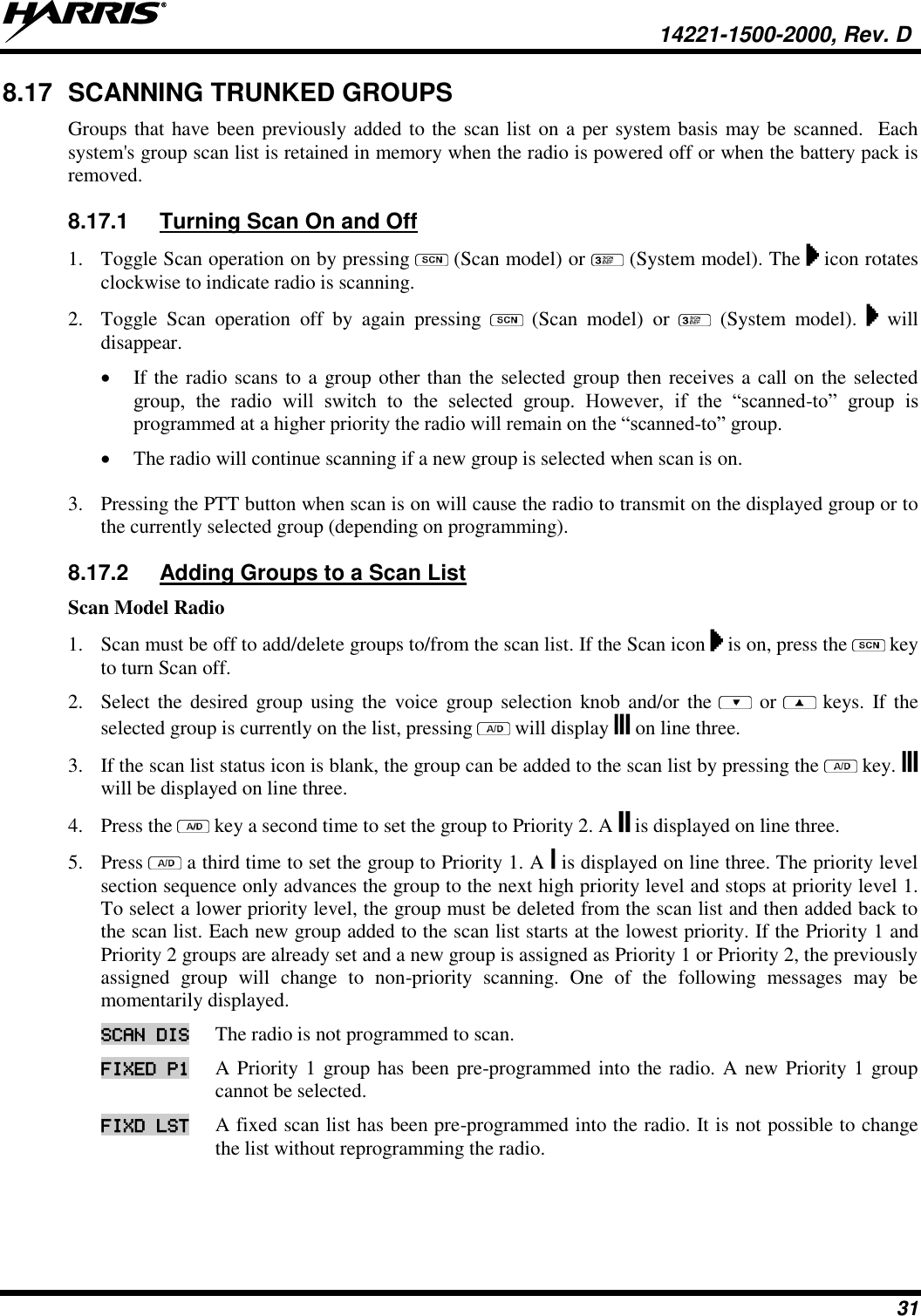
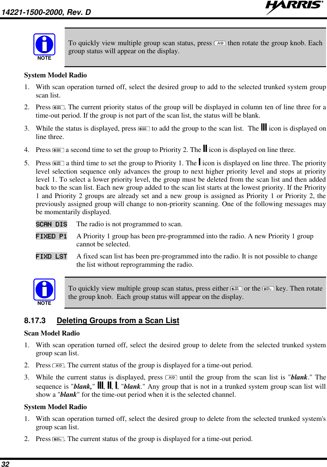
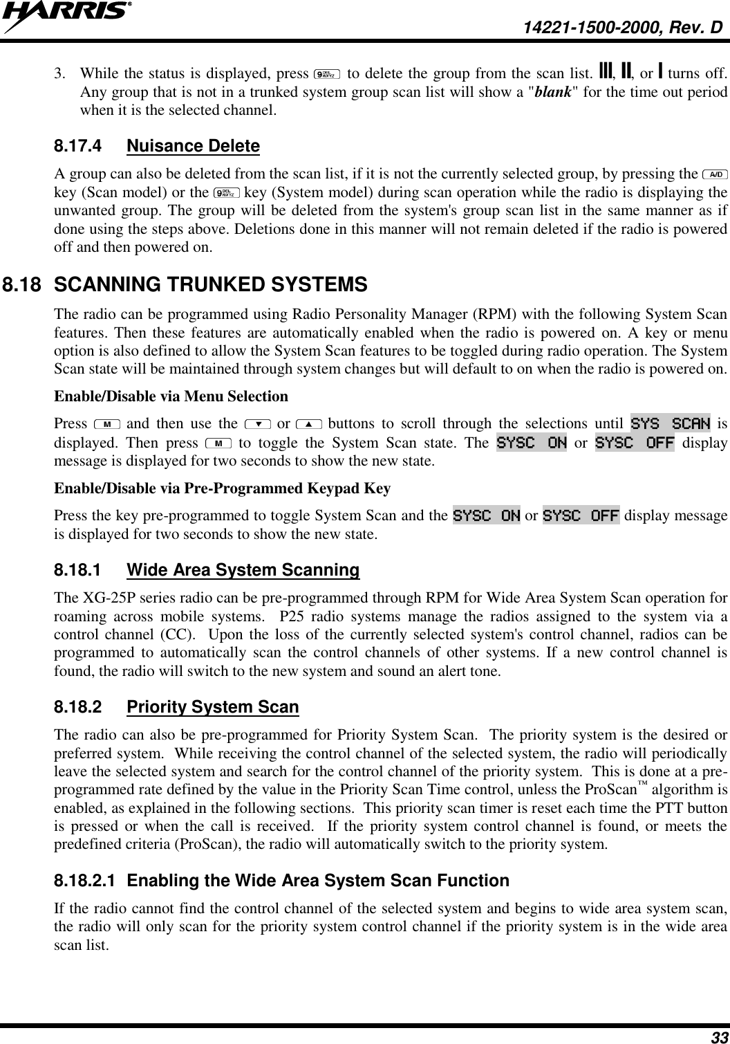
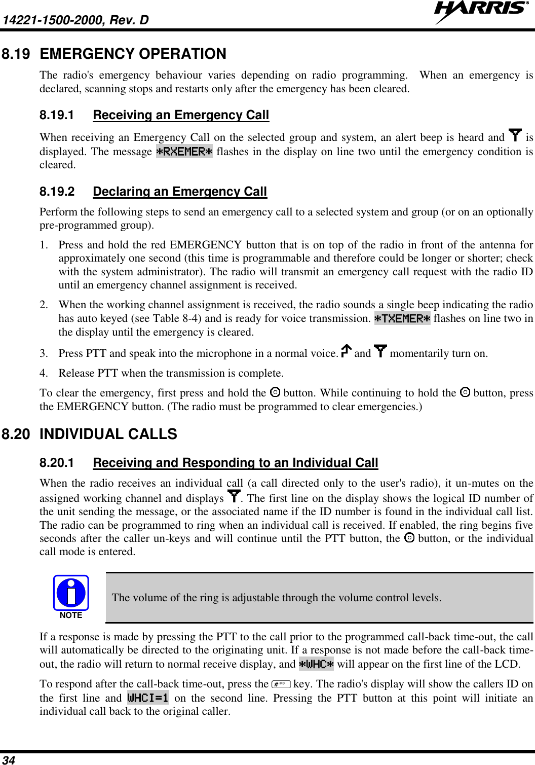
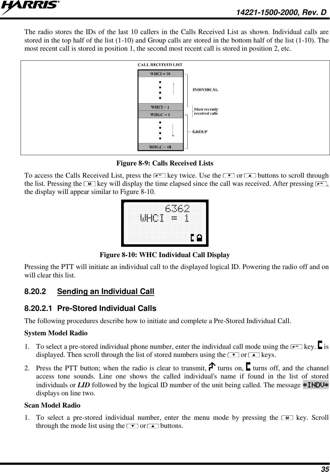
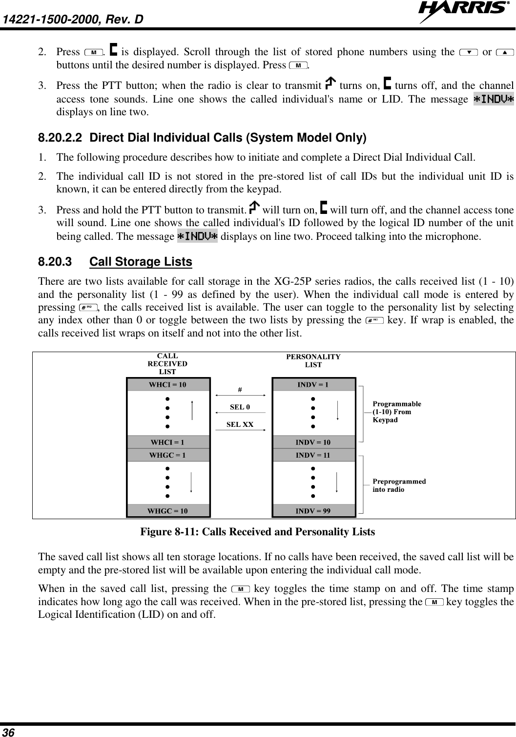
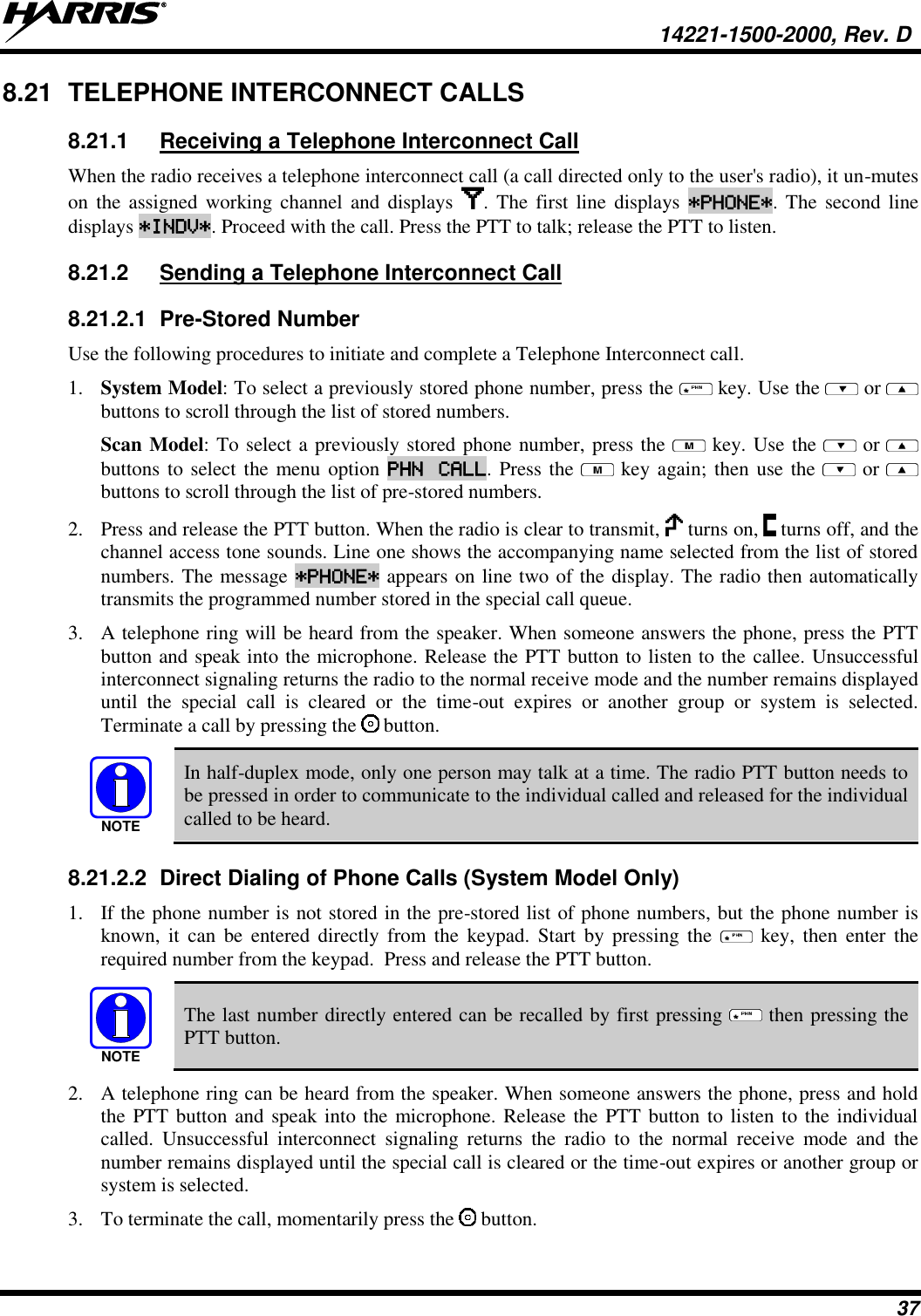
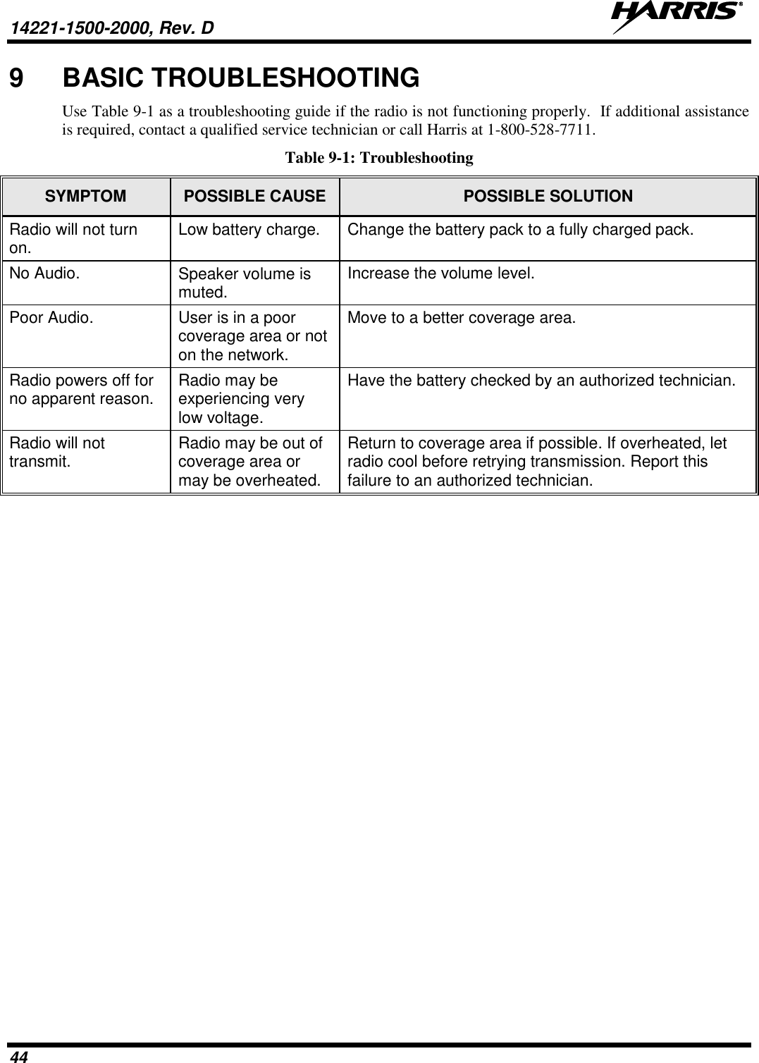
![14221-1500-2000, Rev. D 18 7 OPTIONS AND ACCESSORIES Table 7-1 lists the Options and Accessories tested for use with the XG-25P series portable radios. Refer to the maintenance manual corresponding to the frequency of your XG-25P or to Harris Products and Services Catalog for a complete list of options and accessories, including those items that do not adversely affect the RF energy exposure. WARNING Always use Harris authorized accessories (antennas, batteries, belt clips, speaker/mics, etc). Use of unauthorized accessories may cause the FCC Occupational/Controlled Exposure RF compliance requirements to be exceeded. (Refer to Table 2-1.) CAUTION Always use the correct options and accessories (battery, antenna, speaker/mic, etc.) for the radio. Immersion rated options must be used with an immersion rated radio. Intrinsically safe options (identified by [FM]) are certified by Factory Mutual (FM) and must only be used with FM certified radios. (Refer to Table 7-1.) Table 7-1: Options and Accessories1 DESCRIPTION PART NUMBER OPTION NUMBER ANTENNAS Helical coil (136-151 MHz) [FM] KRE 101 1219/1 DP-NC1B Helical coil (150-162 MHz) [FM] KRE 101 1219/2 DP-NC1C Helical coil (162-174 MHz) [FM] KRE 101 1219/3 DP-NC1D Helical coil (150-174 MHz) [FM] KRE 101 1219/21 DP-NC5W Wideband Whip (764-870 MHz) [FM] KRE 101 1506/2 DP-NC5X Wideband Whip (806-870 MHz) [FM] KRE 101 1506/1 DP-NC5K 1/4 - wave whip (378-430 MHz) KRE 101 1223/10 DP-NC1L Helical stub (403-430 MHz) KRE 101 1219/10 DP-NC1U Helical stub (378-403 MHz) KRE 101 1219/9 DP-NC5B Helical stub (440-494 MHz) KRE 101 1219/12 DP-NC1F ¼ Wave Whip (440-512 MHz) KRE 101 1223/12 BATTERIES NiMH, [FM] BT-023406-004 DP-PA2A Li Ion BT-023406-005 DP-PA9Y NiMH BT-023406-003 DP-PA9X Lithium Polymer BT-023436-001 DP-PA2U CHARGERS Charger, Single Bay, Tri-Chemistry, XG-25P CH-104560-017 DP-CH4G Charger, 6-Bay, Tri-Chemistry, XG-25P CH-104570-017 DP-CH4H AUDIO ACCESSORIES No Ant. (cc) MC-023933-001 DP-AE9D Earphone for speaker/mic [FM] LS103239V1 DP-AE3Z Earphone for speaker/mic, right angle jack [FM] LS103239V2 Ruggedized Speaker Mic-Coil Cord [FM] MC-011617-601 DP-AE6C Standard Speaker Mic - Non Ant [FM] MC-011617-701 DP-AE6A Speaker Mic, Rugged, Coiled Cord, Hi-Visibility MC-011617-606 DP-AE4C Microphone, GPS, P25 MC-009104-002 DP-AE9R 1 Options and Accessories table updated in 14221-1500-2000, Rev. D.](https://usermanual.wiki/HARRIS/TR-0109-E.Operations-Manual/User-Guide-2019676-Page-18.png)