HARRIS TR-0132-E XG-75M/M7300 Series Mobile Radio User Manual
HARRIS CORPORATION XG-75M/M7300 Series Mobile Radio
HARRIS >
User Manual

Rhein Tech Laboratories, Inc. Client: Harris Corporation
360 Herndon Parkway Model #: XG-75M/M7300/M5300,35W
Suite 1400 ID’s: OWDTR-0132-E/3636B-0132
Herndon, VA20170 Standards: FCC Part 90
http://www.rheintech.com Report #: 2014021
166 of 199
Appendix O: Manual
Please refer to the Operators Manuals and Safety Manuals.
Operator’s Manual
MM-014716-
001
Rev. P, Apr
/15
XG-75M/M7300 Series
Mobile Radios
MM-014716-001, Rev. P
2
MANUAL REVISION HISTORY
REV
DATE
REASON FOR CHANGE
C
Sep/09
Added VHF antennas, added “Enable/Disable Volume Side Tone,” and updated to Harris format.
D
Apr/10
Added keypad lock/unlock instructions for ECP, added REGISTER and BND SCAN to P25T
status messages.
E
Jan/11
Updated antenna information; other minor updates.
F
Apr/11
Updated for OTP R17, consolidated EDACS, Conventional, P25 operation into one section.
G
Aug/11
Updated antennas; removed reference to ambient light sensor, minor edits.
H
Oct/11
Added Part 80 information.
J
Jan/12
Updated antennas and updated warranty.
K
Oct/12
Added VHF antennas. Added stealth mode, PIN entry, and Control and Status Services.
L
Jun/13
Added Audio Playback. Updated OpenSky operation.
M
Mar/14
Added support for XG-75M. Added Sections 7.37 and 7.38. Updated Data TX/RX Indications.
N
Oct/14
Updated for XGP R4A – added Voice Annunciation and APPENDIX A.
P
Apr/15
Updated for XGP R5A. Added Preset Buttons to EDACS, Conventional, and P25 operation
section. Added French Safety section.
ACKNOWLEDGEMENT
This device is made under license under one or more of the following US patents: 4,590,473; 4,636,791; 5,148,482; 5,185,796; 5,271,017;
5,377,229; 4,716,407; 4,972,460; 5,502,767; 5,146,497; 5,164,986; 5,185,795; 5,226,084; 5,247,579; ; 5,491,772; 5,517,511; 5,630,011;
5,649,050; 5,701,390; 5,715,365; 5,754,974; 5,826,222; 5,870,405; 6,161,089; and 6,199,037 B1. DVSI claims certain rights, including
patent rights under aforementioned U.S. patents, and under other U.S. and foreign patents and patents pending. Any use of this software or
technology requires a separate written license from DVSI. CREDITS
EDACS, OpenSky, Harris, VIDA, and assuredcommunications are registered trademarks of Harris Corporation.
AMBE is a registered trademark and IMBE, AMBE+, and AMBE+2 are trademarks of Digital Voice Systems, Inc.
All other brand and product names are trademarks, registered trademarks, or service marks of their respective holders.
NOTICE!
The material contained herein is subject to U.S. export approval. No export or re-export is permitted without written approval from the U.S.
Government. Rated: EAR99 in accordance with U.S. Dept. of Commerce regulations 15CFR774, Export Administration Regulations.
Information and descriptions contained herein are the property of Harris Corporation. Such information and descriptions may not be copied
or reproduced by any means, or disseminated or distributed without the express prior written permission of Harris Corporation, PSPC
Division, 221 Jefferson Ridge Parkway, Lynchburg, VA 24501.
Repairs to this equipment should be made only by an authorized service technician or facility designated by the supplier. Any repairs,
alterations or substitutions of recommended parts made by the user to this equipment not approved by the manufacturer could void the
user's authority to operate the equipment in addition to the manufacturer's warranty.
This product conforms to the European Union WEEE Directive 20
12/19/EU. Do not dispose of this product in a public
landfill. Take it to a recycling center at the end of its life.
This manual is published by Harris Corporation without any warranty. Improvements and changes to this manual necessitated by
typographical errors, inaccuracies of current information, or improvements to programs and/or equipment, may be made by Harris
Corporation
at any time and
without notice. Such changes will be incorporated into new editions of this manual. No part of this manual
may be reproduced or transmitted in any form or by any means, electronic or mechanical, including photocopying and recording,
for any
purpose, withou
t the express written permission of Harris Corporation.
Copyright © 2008-2015 Harris Corporation.

MM-014716-001, Rev. P
3
TABLE OF CONTENTS
Page
1.
REGULATORY AND SAFETY INFORMATION ............................................................................. 9
1.1 SAFETY SYMBOL CONVENTIONS ......................................................................................... 9
1.2 REGULATORY APPROVALS ................................................................................................. 10
1.2.1 Applicable Type Acceptance/Certification Numbers .................................................... 10
1.3 RADIO FREQUENCY INTERFERENCE ................................................................................. 11
1.3.1 FCC Part 15 ................................................................................................................... 11
1.3.2 Industry Canada ............................................................................................................. 11
1.4 RF ENERGY EXPOSURE AWARENESS AND CONTROL INFORMATION FOR FCC
OCCUPATIONAL USE REQUIREMENTS ............................................................................. 11
1.4.1 Federal Communications Commission Regulations ...................................................... 12
1.5 COMPLIANCE WITH RF EXPOSURE STANDARDS ........................................................... 12
1.5.1 Mobile Antennas ............................................................................................................ 13
1.5.2 Approved Accessories ................................................................................................... 13
1.5.3 Mobile Antennas (Vehicle Installations) ....................................................................... 14
1.5.4 Mobile Antennas (Motorcycle Installations) ................................................................. 17
1.6 OCCUPATIONAL SAFETY GUIDELINES AND SAFETY TRAINING INFORMATION .. 18
1.7 COMMON HAZARDS .............................................................................................................. 18
1.8 SAFE DRIVING RECOMMENDAT IONS ................................................................................ 19
1.9 OPERATING RULES AND REGULATIONS .......................................................................... 20
1.10 OPERATING TIPS ..................................................................................................................... 20
2.
RENSEIGNEMENTS SUR LA RÉGLEMENTATION ET SÉCURITÉ ....................................... 22
2.1 CONVENTIONS SUR LES SYMBOLES DE SÉCURITÉ ....................................................... 22
2.2 CONFORMITÉ À LA RÉGLEMENTATION ........................................................................... 23
2.2.1 Type Applicable Numéros Acceptation / Certification ................................................. 23
2.3 INTERFÉRENCE DES RADIOFRÉQUENCES ....................................................................... 23
2.3.1 Partie 15 de la FCC ........................................................................................................ 23
2.3.2 Industrie Canada ............................................................................................................ 23
2.4 RENSEIGNEMENTS SUR UNE EXPOSITION À L’ÉNERGIE DES RF ............................... 24
2.4.1 Renseignements Sur Le Contrôle Et La Sensibilisation À L’énergie Des RF Pour Les
Exigences D’une Utilisation Professionnelle De La FCC ............................................. 24
2.5 CONFORMITÉ AUX NORMES D’EXPOSITION AUX RF ................................................... 25
2.5.1 Antennes mobiles .......................................................................................................... 26
2.5.2 Accessoires approuvés ................................................................................................... 26
2.5.3 Monté Antennes (véhicule)............................................................................................ 27
2.5.4 Monté Antennes (Motocyclette) .................................................................................... 32
2.6 RENSEIGNEMENTS SUR LA FORMATION SUR LA SANTÉ ET LA SÉCURITÉ AU
TRAVAIL ................................................................................................................................... 33
2.7 DANGERS COURANTS ........................................................................................................... 33
2.8 RECOMMANDATIONS POUR UNE CONDUITE SÉCURITAIRE ....................................... 34
2.9 RÈGLES ET RÉGLEMENTATIONS D'UTILISATION .......................................................... 35
3.
MARINE FREQUENCIES .................................................................................................................. 36
4.
PRODUCT DESCRIPTION ................................................................................................................ 42
5.
CHANGE OPERATING MODE (700/800 MHZ RADIOS ONLY) ................................................ 43
5.1 CHANGE FROM OTP MODE ................................................................................................... 43
5.2 CHANGE TO OTP MODE......................................................................................................... 43

MM-014716-001, Rev. P
4
TABLE OF CONTENTS
Page
6.
OPENSKY OPERATION (700/800 MHZ RADIOS ONLY) ............................................................ 44
6.1 CH-721 FRONT PANEL COMPONENTS ................................................................................ 44
6.2 POWER UP AND VOLUME CONTROL ................................................................................. 46
6.2.1 Power Up ....................................................................................................................... 46
6.2.2 Volume Control ............................................................................................................. 46
6.3 SELF-TEST ................................................................................................................................. 46
6.4 LOGIN TO THE NETWORK .................................................................................................... 46
6.5 LOG OFF THE NETWORK ....................................................................................................... 47
6.6 TURN THE RADIO OFF ........................................................................................................... 47
6.7 MENU DISPLAY AND CONTROL AREA .............................................................................. 47
6.8 RADIO STATUS ICONS ........................................................................................................... 48
6.9 DWELL DISPLAY ..................................................................................................................... 48
6.10 ERROR MESSAGES .................................................................................................................. 48
6.11 PERSONALITY.......................................................................................................................... 50
6.11.1 Profiles ........................................................................................................................... 50
6.11.2 Talk Groups ................................................................................................................... 51
6.12 ALERT TONES .......................................................................................................................... 52
6.13 BASIC MENU STRUCTURE .................................................................................................... 53
6.14 DUAL-TONE MULTI-FREQUENCY ....................................................................................... 55
6.15 KEYPAD ..................................................................................................................................... 56
6.15.1 Keypad Commands (System Model Control Head) ...................................................... 56
6.15.2 Quick Buttons (System Model Only) ............................................................................ 57
6.15.3 Keypad Lock/Unlock ..................................................................................................... 57
6.15.4 Password Entry .............................................................................................................. 57
6.15.5 DTMF Overdial ............................................................................................................. 58
6.16 CHANGE THE ACTIVE PROFILE ........................................................................................... 58
6.17 ENABLE/DISABLE VOLUME SIDE TONE ............................................................................ 58
6.18 CHECK OR CHANGE THE SELECTED TALK GROUP ....................................................... 58
6.19 ADJUST DISPLAY AND BUTTON BACKLIGHT BRIGHTNESS ........................................ 58
6.20 STEALTH MODE ...................................................................................................................... 59
6.20.1 Enable Stealth Mode ...................................................................................................... 59
6.20.2 Disable Stealth Mode ..................................................................................................... 59
6.21 ADJUST SIDE TONE AUDIO LEVEL ..................................................................................... 59
6.22 CHANGE OPERATING MODE ................................................................................................ 60
6.23 RECEIVE AND TRANSMIT VOICE CALLS .......................................................................... 60
6.23.1 Receive a Voice Call ..................................................................................................... 60
6.23.2 Transmit a Voice Call .................................................................................................... 61
6.24 ADJUST AUDIO TREBLE LEVEL .......................................................................................... 61
6.25 INTERCOM MODE ................................................................................................................... 61
6.26 TALK GROUP LOCK OUT ....................................................................................................... 62
6.26.1 Lock Out a Talk Group .................................................................................................. 62
6.26.2 Unlock a Talk Group ..................................................................................................... 63
6.27 SCANNING ................................................................................................................................ 63
6.27.1 Check or Change Active Scan Mode ............................................................................. 64
6.27.2 Scan Priority .................................................................................................................. 64
6.27.3 Change Priority 1 and Priority 2 Talk Groups ............................................................... 64
6.27.4 Change Priority 3 Talk Groups ...................................................................................... 64

MM-014716-001, Rev. P
5
TABLE OF CONTENTS
Page
6.28 MAKE SELECTIVE CALLS ..................................................................................................... 65
6.28.1 Manually Dial a Selective Call (System Model Control Head) ..................................... 65
6.28.2 Speed Dial a Selective Call............................................................................................ 66
6.28.3 Receive a Selective Call ................................................................................................ 66
6.28.4 Terminate a Selective Call ............................................................................................. 66
6.29 SELECTIVE ALERT .................................................................................................................. 66
6.29.1 Send Selective Alert Messages ...................................................................................... 67
6.29.2 Receive Messages .......................................................................................................... 68
6.29.3 Define Pre-Programmed Messages ................................................................................ 68
6.30 TELEPHONE INTERCONNECT CALLS (SYSTEM MODEL CONTROL HEAD) .............. 68
6.30.1 Place an Interconnect Call ............................................................................................. 68
6.30.2 Receive an Interconnect Call ......................................................................................... 69
6.31 EMERGENCY COMMUNICATIONS ...................................................................................... 69
6.31.1 Declare an Emergency Call or Alert .............................................................................. 69
6.31.2 Silent Emergency ........................................................................................................... 70
6.31.3 Clear an Emergency Call or Alert ................................................................................. 70
6.31.4 Receive an Emergency Call ........................................................................................... 70
6.31.5 Dismiss an Emergency Call ........................................................................................... 71
6.32 ENCRYPTION ........................................................................................................................... 71
6.32.1 Automatic Encryption .................................................................................................... 71
6.32.2 Manual Encryption (System Model) ............................................................................. 72
6.33 PRESET BUTTONS ................................................................................................................... 73
6.34 STATUS MESSAGES ................................................................................................................ 73
6.34.1 Send Status Message via the Keypad (System Model Only) ......................................... 73
6.34.2 Send Status Message via the Menu ............................................................................... 74
6.35 REQUEST TO TALK (RTT) MESSAGES ................................................................................ 74
6.35.1 Send RTT Message via the Keypad (System Model Radios Only) ............................... 74
6.35.2 Send RTT Message via the Menu .................................................................................. 74
6.35.3 Send RTT Automatic Normal Message via the Quick Button ...................................... 74
6.35.4 Send RTT Automatic Priority Message via the Quick Button ...................................... 74
6.36 GPS COORDINATES ................................................................................................................ 75
6.37 SCENE-OF-INCIDENT MODE ................................................................................................. 75
7.
EDACS/CONVENTIONAL/P25 (ECP/XGP) OPERATION ........................................................... 77
7.1 TURN THE RADIO ON ............................................................................................................. 77
7.2 CH-721 FRONT PANEL COMPONENTS ................................................................................ 77
7.3 KEYPAD LOCK/UNLOCK ....................................................................................................... 79
7.4 PRESET BUTTONS ................................................................................................................... 79
7.5 RADIO STATUS ICONS ........................................................................................................... 80
7.6 MESSAGES ................................................................................................................................ 81
7.7 ALERT TONES .......................................................................................................................... 83
7.8 MENU ......................................................................................................................................... 84
7.9 FEATURE ENCRYPTION DISPLAY ....................................................................................... 85
7.9.1 Serial Number ROM (12 Hex Digits) ............................................................................ 86
7.9.2 Feature Encryption Data Stream .................................................................................... 86
7.9.3 Features Enabled ............................................................................................................ 87
7.10 VOICE ANNUNCIATION ......................................................................................................... 88
7.11 SYSTEM/GROUP/CHANNEL SELECTION............................................................................ 88

MM-014716-001, Rev. P
6
TABLE OF CONTENTS
Page
7.11.1 System Selection ............................................................................................................ 88
7.11.2 Group and Channel Selection ........................................................................................ 88
7.12 LAST SYSTEM/GROUP/CHANNEL RECALL ....................................................................... 89
7.13 ENCRYPTION ........................................................................................................................... 89
7.13.1 Displaying the Currently Used Cryptographic Key Number ......................................... 89
7.13.2 Key Zero ........................................................................................................................ 90
7.13.3 Receive an Encrypted Call ............................................................................................. 90
7.13.4 Transmit an Encrypted Call ........................................................................................... 90
7.13.5 Emergencies on Encrypted Group ................................................................................. 90
7.14 MACRO KEY OPERATION ..................................................................................................... 91
7.15 RECEIVE A CALL ..................................................................................................................... 91
7.16 TRANSMIT A CALL ................................................................................................................. 91
7.17 CONVENTIONAL FAILSOFT (EDACS) ................................................................................. 91
7.18 EMERGENCY OPERATION .................................................................................................... 92
7.18.1 Receive an Emergency Call ........................................................................................... 92
7.18.2 Declare an Emergency ................................................................................................... 92
7.19 MIXED SYSTEM ZONES ......................................................................................................... 93
7.20 CALLER ID ................................................................................................................................ 93
7.21 STEALTH MODE ...................................................................................................................... 93
7.22 SYSTEM SCAN OPERATION (EDACS AND P25 TRUNKED) ............................................ 94
7.22.1 Wide Area System Scan (WA Scan) ............................................................................. 94
7.22.2 ProScan™ ...................................................................................................................... 94
7.22.3 Priority System Scan...................................................................................................... 94
7.22.4 When Wide Area System Scan is Enabled .................................................................... 94
7.22.5 When ProScan Is Enabled ............................................................................................. 94
7.22.6 Menu Selection .............................................................................................................. 95
7.22.7 Pre-Programmed Keypad Key ....................................................................................... 95
7.23 SCAN OPERATION................................................................................................................... 95
7.23.1 Add Groups or Channels to a Scan List ......................................................................... 95
7.23.2 Delete Groups or Channels from a Scan List ................................................................ 96
7.23.3 Nuisance Delete ............................................................................................................. 96
7.23.4 Turn Scan On ................................................................................................................. 96
7.23.5 Priority Group/Channel Scanning .................................................................................. 97
7.23.6 Turn Scan Off ................................................................................................................ 97
7.23.7 Mixed Zone Scan ........................................................................................................... 97
7.24 INDIVIDUAL CALLS (EDACS AND P25 MODES) ............................................................... 98
7.24.1 Receive and Respond to an Individual Call ................................................................... 98
7.24.2 Call Storage Lists ........................................................................................................... 99
7.24.3 Send an Individual Call ................................................................................................. 99
7.25 SCAT™ OPERATION ............................................................................................................. 100
7.26 TELEPHONE INTERCONNECT CALLS (EDACS AND P25) ............................................. 100
7.26.1 Receive a Telephone Interconnect Call ....................................................................... 100
7.26.2 Send a Telephone Interconnect Call ............................................................................ 100
7.26.3 DTMF Overdial/Conventional Mode Telephone Interconnect .................................... 101
7.26.4 Programmable Entries ................................................................................................. 101
7.27 MOBILE DATA (EDACS AND P25 TRUNKED) .................................................................. 102
7.27.1 Displays ....................................................................................................................... 102
7.27.2 Data Off Operation ...................................................................................................... 102

MM-014716-001, Rev. P
7
TABLE OF CONTENTS
Page
7.27.3 Data On Operation ....................................................................................................... 102
7.27.4 Exiting Data Calls ........................................................................................................ 103
7.27.5 Scan Lockout Mode ..................................................................................................... 103
7.27.6 Data Lockout Mode ..................................................................................................... 103
7.28 STATUS/MESSAGE OPERATION (EDACS AND P25 TRUNKED) ................................... 103
7.28.1 Status Operation .......................................................................................................... 104
7.28.2 Message Operation ...................................................................................................... 104
7.29 EDACS CONVENTIONAL P1 SCAN .................................................................................... 105
7.30 DYNAMIC REGROUP OPERATION (EDACS) .................................................................... 105
7.31 PAGE (P25 TRUNKED ONLY) .............................................................................................. 105
7.32 SQUELCH ADJUST (CONVENTIONAL) ............................................................................. 105
7.32.1 Menu Selection ............................................................................................................ 106
7.32.2 Pre-Programmed Keypad Key ..................................................................................... 106
7.33 TYPE 99 DECODE (ANALOG CONVENTIONAL) .............................................................. 106
7.33.1 Menu Selection ............................................................................................................ 107
7.33.2 Pre-Programmed Keypad Key ..................................................................................... 107
7.34 TALK-AROUND (ANALOG CONVENTIONAL) ................................................................. 107
7.35 CONTROL AND STATUS SERVICE ..................................................................................... 107
7.36 AUDIO PLAYBACK ............................................................................................................... 108
7.37 RADIO TEXTLINK OPERATION .......................................................................................... 108
7.37.1 Send TextLink Messages ............................................................................................. 108
7.37.2 Receive TextLink Messages ........................................................................................ 108
7.37.3 Delete TextLink Messages .......................................................................................... 108
7.37.4 Display Current Time .................................................................................................. 109
7.38 VIEW GPS INFORMATION ................................................................................................... 109
8.
BASIC TROUBLESHOOTING ........................................................................................................ 110
9.
CUSTOMER SERVICE .................................................................................................................... 111
9.1 CUSTOMER CARE ................................................................................................................. 111
9.2 TECHNICAL ASSISTANCE ................................................................................................... 111
10.
KEYPAD REMAPPING .................................................................................................................... 112
11.
RADIO SETUP ................................................................................................................................... 113
12.
WARRANTY ...................................................................................................................................... 116
APPENDIX A
- CONFIGURING ENCRYPTION ................................................................................. 117
FIGURES
Figure 6-1: System Model ....................................................................................................................... 44
Figure 6-2: Scan Model ........................................................................................................................... 44
Figure 6-3: Typical Display ..................................................................................................................... 47
Figure 6-4: Personality Structure Example ............................................................................................. 51
Figure 7-1: System Model ....................................................................................................................... 78
Figure 7-2: Scan Model ........................................................................................................................... 78
Figure 7-3: Typical Display ..................................................................................................................... 80

MM-014716-001, Rev. P
8
TABLE OF CONTENTS
Page
TABLES
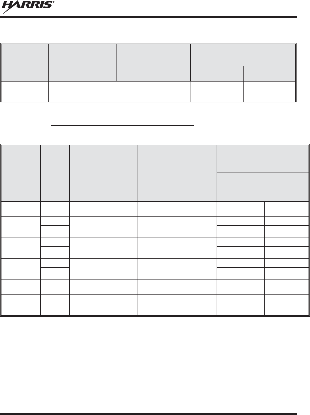
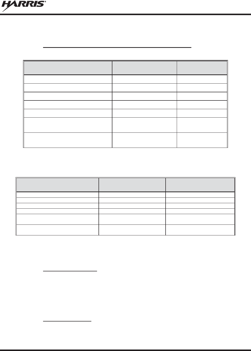
Table 1-1: FCC Type Acceptance .......................................................................................................... 10
Table 1-2: Industry Canada Type Acceptance........................................................................................ 10
Table 1-3: Rated Power and Recommended Minimum Safe Lateral Distance (Vehicle
Installations) .......................................................................................................................... 14
Table 1-4: Rated Power and Recommended Minimum Safe Lateral Distance (Motorcycle
Installation) ........................................................................................................................... 17
Tableau 2-1: FCC Type de Acceptation ................................................................................................. 23
Tableau 2-2: Type de Canada Industrie Acceptation ............................................................................. 23
Tableau 2-3 : Distance latérale sécuritaire minimale recommandée d’une antenne de
transmission branchée sur une radio mobile ......................................................................... 27
Tableau 2-4: Distance latérale sécuritaire minimale recommandée d’une antenne de
transmission branchée sur une radio Motocyclette ............................................................... 32
Table 3-1: Marine Frequencies ................................................................................................................ 36
Table 6-1: Front Panel Default Controls and Functions .......................................................................... 45
Table 6-2: Icons and Descriptions ........................................................................................................... 48
Table 6-3: XG-75M/M7300 OpenSky Mode Alert Tones ...................................................................... 52
Table 6-4: Basic Menu Structure ............................................................................................................. 53
Table 6-5: Keypad Function Commands ................................................................................................. 56
Table 6-6: Quick Button Functions ......................................................................................................... 57
Table 6-7: Scan Modes ............................................................................................................................ 63
Table 6-8: Status of Selective Call .......................................................................................................... 65
Table 6-9: Status of Selective Alert ......................................................................................................... 67
Table 7-1: Front Panel Default Controls and Functions .......................................................................... 78
Table 7-2: Icons and Descriptions ........................................................................................................... 80
Table 7-3: Radio Messages ..................................................................................................................... 81
Table 7-4: Alert Tones ............................................................................................................................. 83
Table 7-5: Menu Item Information .......................................................................................................... 84
Table 7-6: Available Feature Numbers ................................................................................................... 87
Table 7-7: Current Cryptographic Key Display ...................................................................................... 90
Table 8-1: Basic Troubleshooting ......................................................................................................... 110
Harris Corporation, Public Safety and Professional Communications (PSPC) Business, continually evaluates its technical
publications for completeness, technical accuracy, and organization. You can assist in this process by submitting your
comments and suggestions to the following:
Harris Corporation fax your comments to: 1-434-455-6851
PSPC Business or
Technical Publications e-mail us at: PSPC_TechPubs@harris.com
221 Jefferson Ridge Parkway
Lynchburg, VA 24501

MM-014716-001, Rev. P
9
1. REGULATORY AND SAFETY INFORMATION
1.1 SAFETY SYMBOL CONVENTIONS
The following conventions are used in this manual to alert the user to general safety precautions that must
be observed during all phases of operation, installation, service, and repair of this product. Failure to
comply with these precautions or with specific warnings elsewhere violates safety standards of design,
manufacture, and intended use of the product. Harris assumes no liability for the customer's failure to
comply with these standards.
The WARNING symbol calls attention to a procedure, practice, or the like, which,
if not correctly performed or
adhered to, could result in personal injury. Do not
proceed beyond a WARNING symbol until the conditions identified are fully
understood or met.
The
CAUTION
symbol calls attention to an operating procedure, practice, or the like,
which, if not performed correctly or adhered to, could result in damage to the equipment
or severely degrade equipment performance.
The
NOTE
symbol calls attention to supplemental information, which may improve
system performance or clarify a process or procedure.
NOTE
MM-014716-001, Rev. P
10
1.2 REGULATORY APPROVALS
1.2.1 Applicable Type Acceptance/Certification Numbers
Table 1-1: FCC Type Acceptance
RADIO
PART NUMBER FREQUENCY
RANGE/WATTAGE
FCC TYPE
ACCEPTANCE
NUMBER
RU
-144750-041
136
-174 MHz, 50 Watt OWDTR-055-E
RU
-144750-051
136
-174 MHz, 110 Watt
OWDTR-056-E
RU
-144750-021
378
-430 MHz, 50 Watt OWDTR-061-E
RU
-144750-031
440
-512 MHz, 50 Watt OWDTR-062-E
14018
-0010-01
330
-380 MHz, 40 Watt N/A
1
RU
-144750-
061 Rev. K or earlier)
764
-806 MHz, 30 Watt
806
-870 MHz, 35 Watt OWDTR-060-E
RU
-144750-
061 (Rev. L or later)
764
-806 MHz, 30 Watt
806
-870 MHz, 35 Watt OWDTR-0132-E
Applicable FCC Rules: Part 15, Part 80*, and Part 90
* FCC Part 80 is for 156-162 MHz only.
Table 1-2: Industry Canada Type Acceptance
RADIO
PART NUMBER
FREQUENCY
RANGE/WATTAGE
IC TYPE ACCEPTANCE
NUMBER
RU
-144750-041
136
-174 MHz, 50 Watt 3636B-0055
RU
-144750-051
136
-174 MHz, 110 Watt
3636B-0056
RU
-144750-021
378
-430 MHz, 50 Watt 3636B-0061
RU
-144750-031
440
-512 MHz, 50 Watt 3636B-0062
14018
-0010-01
330
-380 MHz, 40 Watt N/A
1
RU
-144750-061
(Rev. K or earlier)
764
-806 MHz, 30 Watt
806
-870 MHz, 35 Watt 3636B-0051
RU
-144750-061
(Rev. L or later)
764
-806 MHz, 30 Watt
806
-870 MHz, 35 Watt 3636B-0132
Applicable Industry Canada Rules: RSS 119; RSS 210
1 The 14018-0010-01 model is not sold or used in North America.
MM-014716-001, Rev. P
11
1.3 RADIO FREQUENCY INTERFERENCE
1.3.1 FCC Part 15
This device complies with Part 15 of the FCC Rules. Operation is subject to the following two conditions:
1. This device may not cause harmful interference; and,
2. This device must accept any interference received, including interference that may cause undesired operation.
1.3.2 Industry Canada
This device complies with Industry Canada license-exempt RSS standard(s). Operation is subject to the
following two conditions: (1) this device may not cause interference, and (2) this device must accept any
interference, including interference that may cause undesired operation of the device.
Le présent appareil est conforme aux CNR d'Industrie Canada applicables aux appareils radio exempts de
licence. L'exploitation est autorisée aux deux conditions suivantes : (1) l'appareil ne doit pas produire de
brouillage, et (2) l'utilisateur de l'appareil doit accepter tout brouillage radioélectrique subi, même si le
brouillage est susceptible d'en compromettre le fonctionnement.
1.4 RF ENERGY EXPOSURE AWARENESS AND CONTROL
INFORMATION FOR FCC OCCUPATIONAL USE REQUIREMENTS
Before using the two-way mobile radio, review the following important RF energy awareness and
control information and operational instructions. Comply with this information and instructions to
ensure compliance with RF exposure guidelines.
This radio is
intended for use in occupational/controlled conditions, where users
have full knowledge of their exposure and can exercise control over their exposure
to remain below RF exposure limits. This radio is NOT authorized for general
population, consumer, or an
y other use.
Changes or modifications not expressly approved by Harris could void the user's
authority to operate the equipment.
This two-way radio uses electromagnetic energy in the radio frequency (RF) spectrum to provide
communications between two or more users over a distance. It uses RF energy or radio waves to send and
receive calls. RF energy is one form of electromagnetic energy. Other forms include, but are not limited
to, electric power, sunlight, and x-rays. RF energy, however, should not be confused with these other
forms of electromagnetic energy, which, when used improperly, can cause biological damage. Very high
levels of x-rays, for example, can damage tissues and genetic material.
Experts in science, engineering, medicine, health, and industry work with organizations to develop
standards for exposure to RF energy. These standards provide recommended levels of RF exposure for
both workers and the general public. These recommended RF exposure levels include substantial margins

MM-014716-001, Rev. P
12
of protection. All two-way radios marketed in North America are designed, manufactured, and tested to
ensure they meet government-established RF exposure levels. In addition, manufacturers also recommend
specific operating instructions to users of two-way radios. These instructions are important because they
inform users about RF energy exposure and provide simple procedures on how to control it. Refer to the
following websites for more information on what RF energy exposure is and how to control exposure to
assure compliance with established RF exposure limits:
http://www.fcc.gov/oet/rfsafety/rf-faqs.html
http://www.osha.gov./SLTC/radiofrequencyradiation/index.html
1.4.1 Federal Communications Commission Regulations
Before it was marketed in the United States, the XG-75M/M7300 series two-way mobile radios were
tested to ensure compliance with FCC RF energy exposure limits for two-way mobile radios. When two-
way radios are used as a consequence of employment, the FCC requires users to be fully aware of and
able to control their exposure to meet occupational requirements. Exposure awareness can be facilitated
by the use of a label directing users to specific user awareness information. The radio has an RF exposure
product label. Also, this Product Safety Manual and the applicable Operator’s Manual include
information and operating instructions required to control RF exposure and to satisfy compliance
requirements.
1.5 COMPLIANCE WITH RF EXPOSURE STANDARDS
The XG-75M/M7300 series two-way mobile radios are designed and tested to comply with a number of
national and international standards and guidelines regarding human exposure to RF electromagnetic
energy. The radios comply with the IEEE and ICNIRP exposure limits for occupational/controlled RF
exposure environment at duty-cycle times of up to 50% (50% transmit, 50% receive) and it is authorized
by the FCC for occupational use. In terms of measuring RF energy for compliance with the FCC exposure
guidelines, each radio’s antenna radiates measurable RF energy only while it is transmitting (talking), not
when it is receiving (listening), or in a standby mode.
The XG-75M/M7300 series two-way mobile radios comply with the following RF energy exposure
standards and guidelines:
x United States Federal Communications Commission (FCC), Code of Federal Regulations; 47
CFR § 2 sub-part J.
x American National Standards Institute (ANSI)/Institute of Electrical and Electronic Engineers (IEEE)
C95.1-2005.
x Institute of Electrical and Electronic Engineers (IEEE) C95.1-2005.
x IC Standard RSS-102, Issue 4, 2010: Spectrum Management and Telecommunications Radio
Standards Specification. Radiofrequency Exposure Compliance of Radiocommunication Apparatus
(All Frequency Bands).
Table 1-3 and Table 1-4 list the recommended minimum safe lateral distances for a
controlled environment and for unaware bystanders in an uncontrolled environment,
from transmitting antennas (i.e., monopoles over a ground plane, or dipoles) at rated
radio power for mobile radios installed in a vehicle. Transmit only when unaware
bystanders are at least the uncontrolled
recommended minimum safe lateral distance
away from the transmitting antenna.

MM-014716-001, Rev. P
13
Based on the highest radiated RF power and the highest antenna gain in antennas used with XG-
75M/M7300 series radios, the distances listed in Table 1-3 and Table 1-4 are considered as safe distances
for controlled and uncontrolled environments with the XG-75M/M7300 series mobile radios transmitting
at a maximum 50% duty cycle:
1.5.1 Mobile Antennas
The antenna(s) for the radio must be installed in accordance with the antenna installation procedures
presented in the radio’s Installation Manual. Also refer to any special instructions included with the
antenna.
Use only approved/supplied antenna(s) or an approved replacement antenna. Unauthorized antennas,
modifications, or attachments can cause the FCC RF exposure limits to be exceeded.
1.5.2 Approved Accessories
The radio has been tested and meets FCC RF guidelines when used with accessories supplied or
designated for use with it. Use of other accessories may not ensure compliance with the FCC’s RF
exposure guidelines, and may violate FCC regulations. For a list of approved accessories, refer to the
radio’s Installation Manual and/or to the Products and Services Catalog.

MM-014716-001, Rev. P
14
1.5.3 Mobile Antennas (Vehicle Installations)
Table 1-3
: Rated Power and Recommended Minimum Safe Lateral Distance (Vehicle Installations)
MOBILE RADIO
FREQUENCY
SPLIT
ANTENNA
PART NUMBER
ANTENNA DESCRIPTION
R
ECOMMENDED MINIMUM LATERAL
HUMAN BODY DISTANCE FROM
TRANSMITTING ANTENNA
CONTROLLED
ENVIRONMENT
UNCONTROLLED
ENVIRONMENT
VHF (50 W)
AN-225002-001
136 to 174
MHz, 0
dBd Gain
24.8 Inches
(63 Centimeters)
55.1 Inches
(140 Centimeters)
VHF (50 W)
AN-225006-001
132 to 960
MHz, 0
dBd Gain*
VHF (50 W)
AN-225002-003
136 to 174
MHz, 3
dBd Gain*
35.0 Inches
(89 Centimeters)
78.0 Inches
(198 Centimeters)
VHF (50 W)
AN-225002-004 136 to 174 MHz, 2.4
dBd
Gain* 32.7 Inches
(83 Centimeters)
72.8 Inches
(185 Centimeters)
VHF (110 W)
AN-225002-001
136 to 174
MHz, 0
dBd Gain
36.6 Inches
(93 Centimeters)
81.9 Inches
(208 Centimeters)
VHF (110 W)
AN-225006-001
132 to 960
MHz, 0
dBd Gain*
VHF (110 W)
AN-225002-003
136 to 174
MHz, 3
dBd Gain*
52.0 Inches
(132 Centimeters)
115.7 Inches
(294 Centimeters)
VHF (110 W)
AN-225002-004 136 to 174 MHz, 2.4
dBd
Gain* 48.4 Inches
(123 Centimeters)
107.9 Inches
(274 Centimeters)
UHF
–
L (50 W)
AN-125001-
001 (mount)
with
AN
-225003-
001 (element)
378 to 430
MHz Standard
Roo
ftop-Mount; 0
dBd Gain
21.3 Inches
(54 Centimeters)
47.2 Inches
(120 Centimeters)
UHF
–
L (50 W)
AN-125001-
001 (mount)
with
AN
-225003-
004 (element)
378 to 430
MHz Standard
Rooftop
-Mount; Low-
Profile
0 dBd Gain
UHF
–
L (50 W)
AN-125001-
003 (mount)
with
AN
-225003-
001 (element)
378 to 430 MHz Thick
Rooftop
-Mount; 0
dBd Gain
UHF
–
L (50 W)
AN-125001-
003 (mount)
with
AN
-225003-
004 (element)
378 to 430
MHz Thick
Rooftop
-Mount; Low-
Profile
0 dBd Gain
UHF
–
L (50 W)
AN-125001-
005 (mount)
with
AN
-225003-
001 (element)
378 to 430 MHz
GPS Combo, Standard
Rooftop
-Mount; 0
dBd Gain
UHF
–
L (50 W)
AN-125001-
005 (mount)
with
AN
-225003-
004 (element)
378 to 430 MHz
GPS Combo, Standard
Rooftop
-Mount; Low-
Profile
0 dBd Gain
UHF
–
L (50 W)
AN-125001-007 (mou
nt)
with
AN
-225003-
001 (element)
378 to 430
MHz Magnetic-
Mount;
0 dBd Gain
UHF
–
L (50 W)
AN-125001-
007 (mount)
with
AN
-225003-
004 (element)
378 to 430
MHz Magnetic-
Mount;
Low-Profile 0
dBd Gain

MM-014716-001, Rev. P
15
Table 1-3
: Rated Power and Recommended Minimum Safe Lateral Distance (Vehicle Installations)
MOBILE RADIO
FREQUENCY
SPLIT
ANTENNA
PART NUMBER
ANTENNA DESCRIPTION
R
ECOMMENDED MINIMUM LATERAL
HUMAN BODY DISTANCE FROM
TRANSMITTING ANTENNA
CONTROLLED
ENVIRONMENT
UNCONTROLLED
ENVIRONMENT
UHF
–
H (50 W)
AN-125001-001 (mount)
with
AN-225004-001 (element)
450 to 512 MHz
Standard Rooftop-
Mount;
0 dBd Gain
20 Inches
(51 Centimeters)
45 Inches
(114 Centimeters)
UHF
–
H (50 W)
AN-125001-001 (mount)
with
AN-225004-004 (element)
450 to 512 MHz
Standard Rooftop-
Mount;
Low-Profile 0 dBd Gain
UHF
– H
(50 W)
AN-125001-003 (mount)
with
AN-225004-001 (element)
450 to 512 MHz
Thick Rooftop-Mount;
0 dBd Gain
UHF
–
H (50 W)
AN-125001-003 (mount)
with
AN-225004-004 (element)
450 to 512 MHz
Thick Rooftop-Mount;
Low-Profile 0 dBd Gain
UHF
–
H (50 W)
AN-125001-005 (mount)
with
AN-225004-001 (element)
450 to 512 MHz
GPS Combo, Standard
Rooftop-Mount; 0 dBd Gain
UHF
–
H (50 W)
AN-125001-
005 (mount)
with
AN
-225004-
004 (element)
450 to 512 MHz
GPS Combo, Standard
Rooftop
-Mount; Low-
Profile
0 dBd Gain
UHF
–
H (50 W)
AN-125001-007 (mount)
with
AN-225004-001 (element)
450 to 512 MHz
Magnetic-Mount;
0 dBd Gain
UHF
–
H (50 W)
AN-125001-007 (mount)
with
AN-225004-004 (element)
450 to 512 MHz
Magnetic
-Mount; Low-
Profile
0 dBd Gain
700/800 MHz
AN-125001-002 (mount)
with
AN-225001-001 (element)
700/800
MHz Standard
Rooftop
-Mount; 3
dBd Gain
9.8 Inches
(25 Centimeters)
21.7 Inches
(55 Centimeters)
700/800 MHz
AN-125001-002 (mount)
with
AN-225001-002 (element)
700/800 MHz Standard
Rooftop-Mount;
Elevated-Feed 3 dBd Gain
700/800 MHz
AN-125001-
002 (mount)
with
AN
-225001-
003 (element)
700/800 MHz Standard
Rooftop-
Mount; Elevated-
Feed, No Ground Plane
3 dBd Gain
700/800 MHz
AN-125001-002 (mount)
with
AN-225001-004 (element)
700/800 MHz Standard
Rooftop-Mount;
Low-Profile 2 dBd Gain
700/800 MHz
AN-125001-002 (mount)
with
AN-225001-005 (element)
700/800
MHz Standard
Rooftop
-Mount; 5
dBd Gain
11.8 Inches
(30 Centimeters)
23.6 Inches
(60 Centimeters)
700/800 MHz
AN-125001-004 (mount)
with
AN-225001-001 (element)
700/800 MHz Thick
Rooftop
-Mount; 3
dBd Gain
9.8 Inches
(25 Centimeters)
21.7 Inches
(55 Centimeters)

MM-014716-001, Rev. P
16
Table 1-3
: Rated Power and Recommended Minimum Safe Lateral Distance (Vehicle Installations)
MOBILE RADIO
FREQUENCY
SPLIT
ANTENNA
PART NUMBER
ANTENNA DESCRIPTION
R
ECOMMENDED MINIMUM LATERAL
HUMAN BODY DISTANCE FROM
TRANSMITTING ANTENNA
CONTROLLED
ENVIRONMENT
UNCONTROLLED
ENVIRONMENT
700/800 MHz
AN-125001-004 (mount)
with
AN-225001-002 (element)
700/800 MHz Thick
Rooftop-
Mount; Elevated-
Feed 3 dBd Gain
9.8 Inches
(25 Centimeters)
21.7 Inches
(55 Centimeters)
700/800 MHz
AN-125001-
004 (mount)
with
AN
-225001-
003 (element)
700/800 MHz Thick
Rooftop-
Mount; Elevated-
Feed, No Ground Plane
3 dBd Gain
700/800 MHz
AN-125001-004 (mount)
with
AN-225001-004 (element)
700/800 MHz Thick
Rooft
op-Mount; Low-
Profile
2 dBd Gain
700/800 MHz
AN-125001-004 (mount)
with
AN-225001-005 (element)
700/800 MHz Thick
Rooftop
-Mount; 5
dBd Gain
11.8 Inches
(30 Centimeters)
23.6 Inches
(60 Centimeters)
700/800 MHz
AN-125001-006 (mount)
with
AN-225001-001 (element)
700/800 MHz GPS Combo
Rooftop-Mount; 3
dBd /
5.15 dBi Gain
9.8 Inches
(25 Centimeters)
21.7 Inches
(55 Centimeters)
700/800 MHz
AN-125001-006 (mount)
with
AN-225001-002 (element)
700/800 MHz GPS Combo
Rooftop-Mount;
Elevated-Feed 3 dBd Gain
70
0/800 MHz
AN-125001-
006 (mount)
with
AN
-225001-
003 (element)
700/800 MHz GPS Combo
Rooftop-
Mount; Elevated-
Feed, No Ground Plane
3 dBd Gain
700/800 MHz
AN-125001-006 (mount)
with
AN-225001-004 (element)
700/800 MHz GPS Combo
Rooftop
-Mount; Low-
Profile
2 dBd Gain
700/800 MHz
AN-125001-006 (mount)
with
AN-225001-005 (element)
700/800 MHz GPS Combo
Rooftop-Mount; 5
dBd /
7.15 dBi Gain
11.8 Inches
(30 Centimeters)
23.6 Inches
(60 Centimeters)
700/800 MHz
AN-125001-008 (mount)
with
AN-225001-001 (element)
700/800 MHz Magnetic
-
Mount; 3 dBd Gain
9.8 Inches
(25 Centimeters)
21.7 Inches
(55 Centimeters)
700/800 MHz
AN-125001-008 (mount)
with
AN-225001-002 (element)
700/800 MHz Magnetic-
Mount;
Elevated-Feed 3 dBd Gain
700/800 MHz
AN-125001-008 (mount)
with
AN-225001-003 (element)
700/800 MHz Magnetic-
Mount; Elevated-
Feed, No
Ground Plane 3 dBd Gain
700/800 MHz
AN-125001-008 (mount)
with
AN-225001-004 (element)
700/800 MHz Magnetic-
Mount;
Low-Profile 2 dBd Gain
700/800 MHz
AN-125001-008 (mount)
with
AN-225001-005 (element)
700/800 MHz Magnetic
-
Mount; 5 dBd Gain 11.8 Inches
(30 Centimeters)
23.6 Inches
(60 Centimeters)
MM-014716-001, Rev. P
17
Table 1-3
: Rated Power and Recommended Minimum Safe Lateral Distance (Vehicle Installations)
MOBILE RADIO
FREQUENCY
SPLIT
ANTENNA
PART NUMBER
ANTENNA DESCRIPTION
R
ECOMMENDED MINIMUM LATERAL
HUMAN BODY DISTANCE FROM
TRANSMITTING ANTENNA
CONTROLLED
ENVIRONMENT
UNCONTROLLED
ENVIRONMENT
700/800 MHz
STI-Co
CCAS-SB-700
760 - 820 MHz Concealed
Peal-and-
Stick Internal-
Mount; dBi Gain
7.9 Inches
(20 Centimeters)
19.7 Inches
(50 Centimeters)
* Element must be trimmed to proper length to minimize antenna system VSWR.
1.5.4 Mobile Antennas (Motorcycle Installations)
Table 1-4: Rated Power and Recommended Minimum Safe Lateral Distance (Motorcycle Installation)
RF
BAND
MAX. TX
POWER
(WATTS)
ANTENNA
PART NUMBER
ANTENNA DESCRIPTION
RECOMMENDED MINIMUM
LATERAL HUMAN BODY
DISTANCE FROM TRANSMITTING
ANTENNA
CONTROLLED
ENVIRONMENT
(Centimeters)
UNCONTROLLE
D
ENVIRONMENT
(Centimeters)
VHF 20
LE-
OM150K.125/TNC
136 to 174 MHz Motorcycle-
Mount; 2.5 dBd Gain
53 118
VHF
18
AN-125001-005 (mount)
with
AN-225002-004 (element)
136 to 174 MHz GPS Combo;
No-Ground-
Plane (NGP);
2.4 dBd Gain
50
—
3.6
— 50
UHF- L
43
AN-125001-005 (mount)
with
AN-225003-005 (element)
378 to 430 MHz GPS Combo,
No
-Ground-Plane (NGP), 0
dBd
Gain
50
—
8.5
— 50
UHF - H
47
AN-125001-005 (mount)
with
AN-225004-005 (element)
450 to 512 MHz GPS Combo,
No
-Ground-Plane (NGP), 0
dBd
Gain
50
—
9.5
— 50
800 MHz
20
LE
-
OM806HDBKTNCDS
800 MHz Motorcycle-Mount;
3.5 dBd Gain
28 72
700 or 800 MHz
20
AN-125001-006 (mount)
with
AN-225001-003 (element)
700/800 MHz GPS Combo; no-
Ground-Plane (NGP);
3 dBd / 5.15 dBi Gain
50 50
MM-014716-001, Rev. P
18
A radio used in a motorcycle installation must be configured with a transmit output
power level less than or equal to the
MAX. TX POWER (WATTS) specificatio
n listed in
Table
1-4
for the respective frequency band and antenna/antenna element. Refer to the
radio’s
Installation Manual for additional information.
When a later
-design motorcycle installation kit is employed
(which uses antenna
element AN
-225001-003 or AN-225002-
004), the coaxial cable between the radio and
the base of the antenna mount cannot be shorter than 44
inches (111.8
centimeters).
Refer to the radio’s
Installation Manual for additional information.
A
radio intended for a non-motorcycle installation should not
be used in a motorcycle
installation unless it is reprogrammed per the procedures presented in the radio’s
Installation Manual
.
1.6 OCCUPATIONAL SAFETY GUIDELINES AND SAFETY TRAINING
INFORMATION
To ensure bodily exposure to RF electromagnetic energy is within the FCC allowable limits for
occupational use. Always adhere to the following basic guidelines:
x The push-to-talk button should only be depressed when intending to send a voice message.
x The radio should only be used for necessary work-related communications.
x The radio should only be used by authorized and trained personnel. It should never be operated by
children.
x Do not attempt any unauthorized modification to the radio. Changes or modifications to the radio may
cause harmful interference and/or cause it to exceed FCC RF exposure limits. Only qualified
personnel should service the radio.
x Always use only authorized accessories (antennas, control heads, speakers/mics, etc.). Use of
unauthorized accessories can cause the FCC RF exposure compliance requirements to be exceeded.
The information listed above provides the user with information needed to make him or her aware of a RF
exposure, and what to do to assure that this radio operates within the FCC exposure limits of this radio.
1.7 COMMON HAZARDS
The operator of any mobile radio should be aware of certain hazards common to
the operation of vehicular radio transmissions. Possible hazards include but are not
limited to:
x Explosive Atmospheres — Just as it is dangerous to fuel a vehicle while its engine is running, be
sure to turn the radio OFF while fueling the vehicle. If the radio is mounted in the trunk of the
vehicle, DO NOT carry containers of fuel in the trunk.
Areas with potentially explosive atmosphere are often, but not always, clearly marked. Turn the radio
OFF when in any area with a potentially explosive atmosphere. It is rare, but not impossible that the
radio or its accessories could generate sparks.

MM-014716-001, Rev. P
19
x Interference To Vehicular Electronic Systems — Electronic fuel injection systems, electronic anti-
skid braking systems, electronic cruise control systems, etc., are typical of the types of electronic
devices that can malfunction due to the lack of protection from radio frequency (RF) energy present
when transmitting. If the vehicle contains such equipment, consult the dealer for the make of vehicle
and enlist his aid in determining if such electronic circuits perform normally when the radio is
transmitting.
x Electric Blasting Caps — To prevent accidental detonation of electric blasting caps, DO NOT use
two-way radios within 1000 feet (305 meters) of blasting operations. Always obey the “Turn Off
Two-Way Radios” (or equivalent) signs posted where electric blasting caps are being used. (OSHA
Standard: 1926.900).
x Radio Frequency Energy — To prevent burns or related physical injury from radio frequency
energy, do not operate the transmitter when anyone outside of the vehicle is within the minimum safe
distance from the antenna as specified in Table 1-3 and Table 1-4. Refer to Section 1.2 for additional
information.
x Vehicles Powered By Liquefied Petroleum (LP) Gas — Radio installation in vehicles powered by
liquefied petroleum gas, where the LP gas container is located in the trunk or other sealed-off space
within the interior of the vehicle, must conform to the National Fire Protection Association standard
NFPA 58. This requires:
¾ The space containing the radio equipment must be isolated by a seal from the space containing
the LP gas container and its fittings.
¾ Outside filling connections must be used for the LP gas container.
¾ The LP gas container space shall be vented to the outside of the vehicle.
x Vehicles Equipped with Airbags — For driver and passenger safety, avoid mounting the radio’s
control head (or any other component) above or near airbag deployment areas. In addition to driver-
side and passenger-side front-impact airbags, some vehicles may also be equipped with side-impact
airbags. For occupant safety, verify the location of all airbags within the vehicle before installing the
radio equipment.
1.8 SAFE DRIVING RECOMMENDATIONS
The American Automobile Association (AAA) advocates the following key safe driving recommenda-
tions:
x Read the literature on the safe operation of the radio.
x Keep both hands on the steering wheel and the microphone in its hanger whenever the vehicle is in
motion.
x Place calls only when the vehicle is stopped.
x When talking from a moving vehicle is unavoidable, drive in the slower lane. Keep conversations
brief.
x If a conversation requires taking notes or complex thought, stop the vehicle in a safe place and
continue the call.
x Whenever using a mobile radio, exercise caution.
MM-014716-001, Rev. P
20
1.9 OPERATING RULES AND REGULATIONS
Two-way radio systems must be operated in accordance with the rules and regulations of the local,
regional, or national government.
In the United States, the XG-75M/M7300 mobile radio must be operated in accordance with the rules and
regulations of the Federal Communications Commission (FCC). Operators of two-way radio equipment
must be thoroughly familiar with the rules that apply to the particular type of radio operation. Following
these rules helps eliminate confusion, assures the most efficient use of the existing radio channels, and
results in a smoothly functioning radio network.
Under U.S. law, operation of an unlicensed radio transmitter within the jurisdiction of
the United States may be punishable by a fine of up to $10,000, imprisonment for up to
two (2) years, or both.
When using a two-way radio, remember these rules:
x It is a violation of FCC rules to interrupt any distress or emergency message. The radio operates in
much the same way as a telephone “party line.” Therefore, always listen to make sure the channel is
clear before transmitting. Emergency calls have priority over all other messages. If someone is
sending an emergency message – such as reporting a fire or asking for help in an accident, do not
transmit unless assistance can be offered.
x The use of profane or obscene language is prohibited by Federal law.
x It is against the law to send false call letters or false distress or emergency messages. The FCC
requires keeping conversations brief and confined to business. Use coded messages whenever
possible to save time.
x Using the radio to send personal messages (except in an emergency) is a violation of FCC rules. Send
only essential messages.
x It is against Federal law to repeat or otherwise make known anything overheard on the radio.
Conversations between others sharing the channel must be regarded as confidential.
x The FCC requires self-identification at certain specific times by means of call letters. Refer to the
rules that apply to the particular type of operation for the proper procedure.
x No changes or adjustments shall be made to the equipment except by an authorized or certified
electronics technician.
1.10 OPERATING TIPS
The following conditions tend to reduce the effective range of two-way radios and should be avoided
whenever possible:
x Operating the radio in areas of low terrain, or while under power lines or bridges.
x Obstructions such as mountains and buildings.

MM-014716-001, Rev. P
21
In areas where transmission or reception is poor, communication improvement may
sometimes be obtained by moving
a few yards in another direction, or moving to a
higher elevation.
NOTE
MM-014716-001, Rev. P
22
2. RENSEIGNEMENTS SUR LA RÉGLEMENTATION ET
SÉCURITÉ
2.1 CONVENTIONS SUR LES SYMBOLES DE SÉCURITÉ
Les conventions suivantes sont utilisées dans le présent manuel pour avertir l’utilisateur des précautions
générales de sécurité qui doivent être observées pendant toutes les phases d’opération, d’entretien et de
réparation de ce produit. Le non-respect de ces précautions ou d’avertissements précisés ailleurs enfreint
les normes de sécurité de la conception, de la fabrication et de l’utilisation prévue du produit. Harris
n’assume aucune responsabilité pour le non-respect de ces normes par le client.
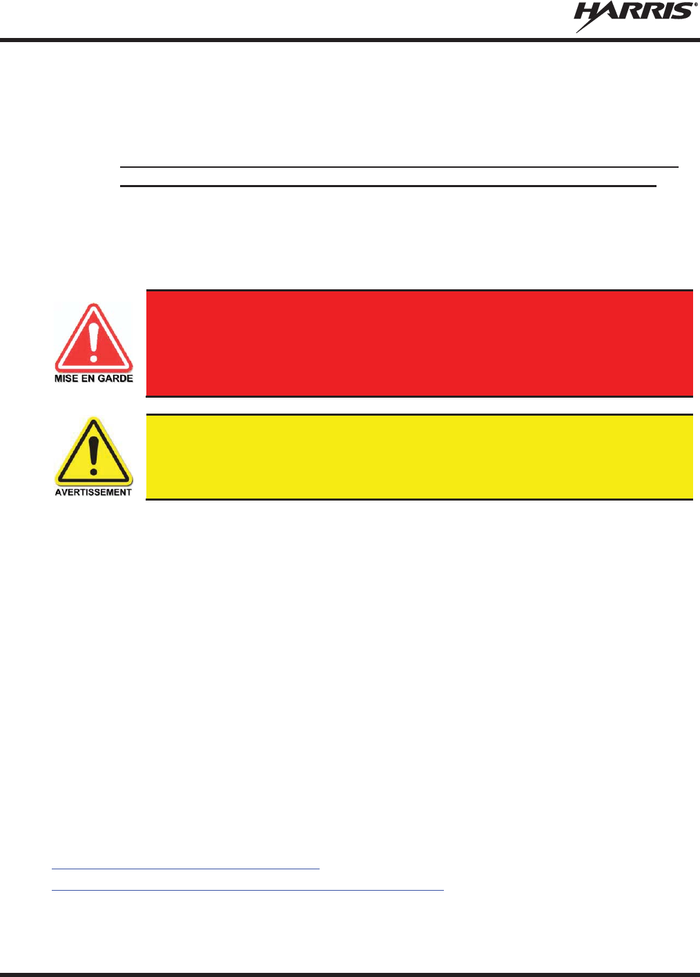
Le symbole MISE EN GARDE attire l’attention sur une procédure ou une
pratique qui, si elle n’est pas correctement effectuée ou observée, pourrait
entraîner une blessure personnelle. Ne pas poursuivre au
-
delà d’un symbole de
MISE EN GARDE avant que les conditions identifiées soient complètement
comprises ou satisfaites.
Le symbole
AVERTISSEMENT attir
e l’attention sur une procédure ou une pratique
opérationnelle qui, si elle n’est pas correctement effectuée ou observée, pourrait
entraîner un bris d’équipement ou une importante baisse de rendement de l’équipement.
Le symbole
REMARQUE attire l’atte
ntion sur des renseignements supplémentaires qui
peuvent améliorer le rendement du système ou clarifier un processus ou une procédure.
MM-014716-001, Rev. P
23
2.2 CONFORMITÉ À LA RÉGLEMENTATION
2.2.1 Type Applicable Numéros Acceptation / Certification
Tableau 2-1: FCC Type de Acceptation
NUMÉRO DE PIÈCE
DE LA RADIO
FRÉQUENCE
RADIO/WATTAGE
FCC TYPE NOMBRE
ACCEPTATION
RU
-144750-041
VHF 136
-
174 MHz, 50 Watt
OWDTR-055-E
RU
-144750-051
VHF 136
-
174 MHz, 110 Watt
OWDTR-056-E
RU
-144750-021
UHF
-L 378-
430 MHz, 50 Watt
OWDTR-061-E
RU
-144750-031
UHF
-H 440-
512 MHz, 50 Watt
OWDTR-062-E
14018
-0010-01
330
-380 MHz, 40 Watt N/R
RU
-144750-061 (Rev. K or earlier)
764
-806 MHz, 30 Watt
806
-870 MHz, 35 Watt OWDTR-060-E
RU
-144750-061 (Rev. L or later)
764
-806 MHz, 30 Watt
806
-870 MHz, 35 Watt OWDTR-0132-E
règles de la FCC applicables: Partie 15, Partie 80*, and Partie 90
* FCC Part 80 est à 156-162 MHz only.
Tableau 2-2: Type de Canada Industrie Acceptation
NUMÉRO DE PIÈCE
DE LA RADIO
FRÉQUENCE
RADIO/WATTAGE
CANADA INDUSTRIE TYPE
NOMBRE ACCEPTATION
RU-144750-041
VHF 136-174 MHz, 50 Watt
3636B-0055
RU-144750-051
VHF 136-174 MHz, 110 Watt
3636B-0056
RU-144750-021
UHF-L 378-430 MHz, 50 Watt
3636B-0061
RU-144750-031
UHF-H 440-512 MHz, 50 Watt
3636B-0062
RU
-144750-061 (Rev. K or earlier)
764-806 MHz, 30 Watt
806-870 MHz, 35 Watt
3636B-0051
RU
-144750-061 (Rev. L or later)
764-806 MHz, 30 Watt
806-870 MHz, 35 Watt
3636B-0132
Reglement applicables d'Industrie Canada: RSS 119; RSS 210
2.3 INTERFÉRENCE DES RADIOFRÉQUENCES
2.3.1 Partie 15 de la FCC
Cet appareil est conforme à la Partie 15 de la réglementation de la FCC. Le fonctionnement est soumis
aux deux conditions suivantes :
1. Cet appareil ne doit pas causer une interférence nuisible; et
2. Cet appareil doit accepter toute interférence reçue, y compris une interférence qui peut causer un
fonctionnement non souhaité.
2.3.2 Industrie Canada
Cet appareil est conforme aux normes RSS exemptées de licence d’Industrie Canada. Le fonctionnement
est soumis aux deux conditions suivantes : (1) cet appareil ne doit pas causer d’interférence et (2) cet
MM-014716-001, Rev. P
24
appareil doit accepter toute interférence, y compris une interférence qui peut causer un fonctionnement
non souhaité de l’appareil.
2.4 RENSEIGNEMENTS SUR UNE EXPOSITION À L’ÉNERGIE DES RF
2.4.1 Renseignements Sur Le Contrôle Et La Sensibilisation À L’énergie Des
RF Pour Les Exigences D’une Utilisation Professionnelle De La FCC
Avant d’utiliser les radios mobiles bidirectionnelles, passez en revue les renseignements et les
instructions opérationnelles importants suivants sur le contrôle et la sensibilisation à l’énergie des
RF. Se conformer à ces renseignements et instructions pour assurer la conformité aux directives
d’exposition aux RF.
Cette radio est destinée à être utilisée dans des conditions professionnelles/
contrôlées, où les utilisateurs ont une pleine connaissance de leur exposition et
peuvent exercer un contrôle sur leur exposition pour rester sous les limites
d’exposition aux RF. Cette radio N’est PAS autorisée pour la population générale,
les consommateurs ou toute autre utilisation.
Des changements ou modifications non expressément approuvés par Harris pourraient
annuler le droit d’utilisation de l’équipement pour l’utilisateur.
Cette radio bidirectionnelle utilise une énergie électromagnétique dans le spectre des radiofréquences
(RF) pour permettre une communication à distance entre deux utilisateurs ou plus. Elle utilise l’énergie
des RF ou les ondes radio pour envoyer et recevoir des appels. L’énergie des RF est une forme d’énergie
électromagnétique. D’autres formes comprennent, entre autres, l’énergie électrique, la lumière du soleil et
les rayons X. Toutefois, l’énergie des RF ne doit pas être confondue avec ces autres formes d’énergie
électromagnétique qui, lorsque mal utilisées, peuvent causer des dommages biologiques. Par exemple, des
niveaux très élevés de rayons X peuvent endommager les tissus et le matériel génétique.
Des experts en science, en ingénierie, en médecine, en santé et de l’industrie travaillent avec des
organismes pour établir des normes pour l’exposition à l’énergie des RF. Ces normes procurent des
niveaux recommandés d’exposition aux RF autant aux travailleurs qu’au grand public. Ces niveaux
d’exposition aux RF recommandés comprennent d’importantes marges de protection. Toutes les radios
bidirectionnelles commercialisées en Amérique du Nord sont conçues, fabriquées et testées pour s’assurer
qu’elles satisfont les niveaux d’exposition aux RF établis par le gouvernement. Les fabricants
recommandent également des consignes d’utilisation particulières aux utilisateurs de radios
bidirectionnelles. Ces instructions sont importantes, car elles informent les utilisateurs sur l’exposition à
l’énergie des RF et donnent des procédures simples sur la manière de contrôler cette exposition.
Consultez les sites Web suivants (en anglais) pour de plus amples renseignements sur ce qu’est
l’exposition à l’énergie des RF et comment contrôler l’exposition pour assurer la conformité aux limites
d’exposition établies :
http://www.fcc.gov/oet/rfsafety/rf-faqs.html
http://www.osha.gov./SLTC/radiofrequencyradiation/index.html

MM-014716-001, Rev. P
25
2.4.1.1 Règlements de la Federal Communications Commission (« Commission
fédérale des communications » aux États-Unis)
Avant d’être mise sur le marché aux États-Unis, la radio mobile bidirectionnelle XG-75M/M7300 a été
testée pour s’assurer de sa conformité aux limites d’exposition à l’énergie des RF de la FCC pour les
radios mobiles bidirectionnelles. Lorsque les radios bidirectionnelles sont utilisées à la suite d’une
embauche, la FCC demande aux utilisateurs de bien connaître et de pouvoir contrôler leur exposition pour
satisfaire les exigences professionnelles. La sensibilisation à l’exposition peut être facilitée par
l’utilisation d’une étiquette qui dirige les utilisateurs vers des renseignements particuliers sur la
sensibilisation de l’utilisateur. La radio possède une étiquette de produit sur l’exposition aux RF. De plus,
le Manuel sur la sécurité du produit et le présent Manuel de l’opérateur comprennent des renseignements
et les consignes d’utilisation nécessaires pour contrôler l’exposition aux RF et pour satisfaire les
exigences de conformité.
2.5 CONFORMITÉ AUX NORMES D’EXPOSITION AUX RF
La radio mobile bidirectionnelle XG-75M/M7300 est conçue et testée pour être conforme à un certain
nombre de normes et directives nationales et internationales quant à l’exposition humaine à l’énergie
électromagnétique des RF. Cette radio est conforme aux limites d’exposition de l’IEEE et de la
Commission internationale de protection contre les rayonnements non ionisants pour un environnement
professionnel/contrôlé d’exposition aux RF à des périodes de cycle de service allant jusqu’à 50 % (50 %
de transmission, 50 % de réception) et elle est autorisée par la FCC pour une utilisation professionnelle.
Sur le plan de la mesure de l’énergie des RF pour la conformité aux directives d’exposition de la FCC,
l’antenne de la radio irradie une énergie des RF mesurable seulement lorsqu’elle transmet (parler), et non
lorsqu’elle reçoit (écouter) ou en mode d’attente.
La radio mobile bidirectionnelle XG-75M/M7300 est conforme aux normes et directives d’exposition à
l’énergie des RF suivantes :
x Federal Communications Commission (FCC) américaine, le Code of Federal Regulations; 47 CFR
§ 2 sous-partie J.
x American National Standards Institute (ANSI)/Institute of Electrical and Electronic Engineers (IEEE)
C95.1-2005.
x Institute of Electrical and Electronic Engineers (IEEE) C95.1-2005.
x IC Standard RSS-102, numéro 4, 2010 : Spectrum Management and Telecommunications Radio
Standards Specification. Radiofrequency Exposure Compliance of Radiocommunication Apparatus
(All Frequency Bands).
Tableau 2-3 par Tableau 2-4 indiquent les distances latérales sécuritaires minimales
recommandées pour un environnement contrôlé et pour les spectateurs ignorants dans
un environnement non contrôlé, d
’antennes de transmission (c.-à-
d., des monopôles sur
un plan de sol, ou des dipôles) à une puissance de radio évaluée
pour les radios mobiles
installées dans un véhicule. Ils ne transmettent que lorsque les spectateurs ignorants
sont au moins à la distance latérale sécuritaire minimale recommandée non contrôlée
de l
’antenne de transmission.
Basées sur la puissance des RF irradiées la plus élevée et le gain d’antenne le plus élevé dans les antennes
à utiliser avec le XG-75M/M7300, les distances indiquées dans les Tableau 2-4 (pour une radio de
motocyclette), Tableau 2-3 (pour la XG-75M/M7300, 136 à 174 MHz, 50-Watt), (pour la XG-
75M/M7300, 136 à 174 MHz, 110-Watt), (pour la XG-75M/M7300, 378 à 512 MHz), (pour la XG-
75M/M7300, 700/800 MHz) sont considérées comme des distances sécuritaires pour des environnements
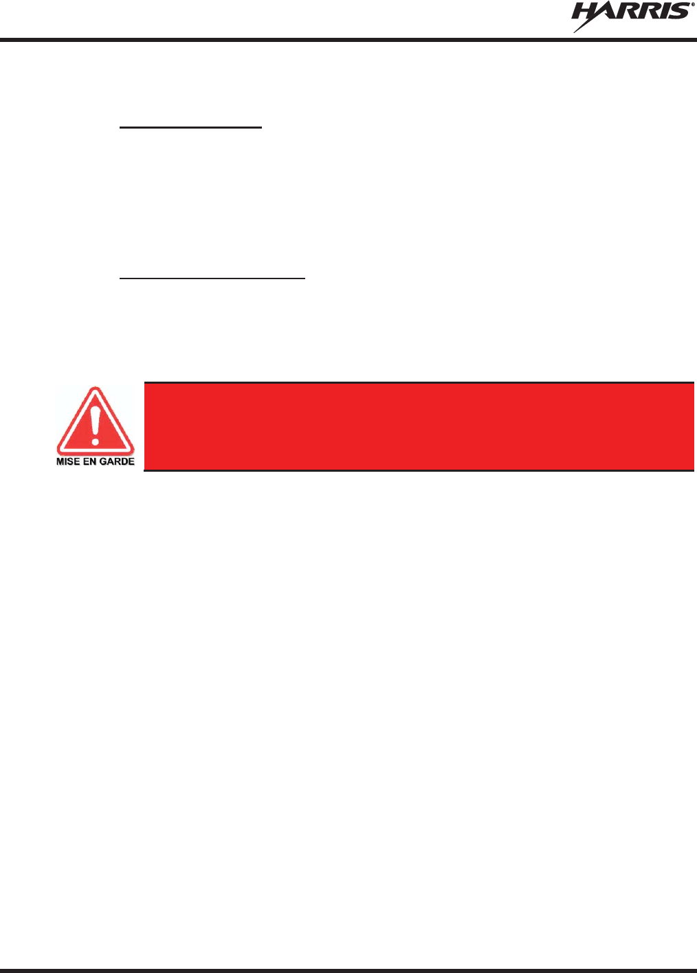
MM-014716-001, Rev. P
26
contrôlés et non contrôlés avec la radio mobile XG-75M/M7300 qui transmet à un cycle de service
maximal de 50 %.
2.5.1 Antennes mobiles
Les antennes pour la radio doivent être installées conformément aux procédures présentées dans le
Manuel sur la sécurité du produit et dans le Manuel d’installation. L’installation est limitée à un ou des
véhicules motorisés en métal avec des plans au sol appropriés.
Utilisez uniquement les antennes approuvées/fournies ou une antenne de remplacement approuvée. Des
antennes, des modifications ou des accessoires non autorisés peuvent causer un dépassement des limites
d’exposition aux RF de la FCC.
2.5.2 Accessoires approuvés
La radio a été testée et satisfait les directives de RF de la FCC lorsqu’elle est utilisée avec les accessoires
fournis ou conçus pour être utilisés avec elle. L’utilisation d’autres accessoires peut ne pas garantir la
conformité aux directives d’exposition de la FCC et peut enfreindre la réglementation de la FCC. Pour
une liste d’accessoires approuvés, consultez le Manuel d’installation ou le Catalogue de produits et
services de Harris.
Utilisez toujours des accessoires autorisés Harris (antennes, haut
-
parleurs/micros,
etc.). L’utilisation d’accessoires non autorisés peut entraîner un dépassement des
exigences de conformité pour une exposition aux RF professionnelle ou contrôlée
de la FCC.

MM-014716-001, Rev. P
27
2.5.3 Monté Antennes (véhicule)
Tableau 2-3 : Distance latérale sécuritaire minimale recommandée d’
une antenne de transmission
branchée sur une radio mobile
RF
BAND
NUMÉRO DE PIÈCE DE
L’ÉLÉMENT DE
L’ANTENNE
DESCRIPTION DE
L’ANTENNE
DISTANCE MINIMALE RECOMMANDÉE DE
L’
ANTENNE DE TRANSMISSION POUR LE
CORPS HUMAIN
ENVIRONNEMENT
CONTRÔLÉ
ENVIRONNEMENT NON
CONTRÔLÉ
VHF (50 W)
AN-225002-001
136 à 174
MHz, gain de 0
dBd
63 cm
(24,8 po) 140 cm
(55,1 po)
VHF (50 W)
AN-225006-001
132 à 960
MHz, gain de 0
dBd
VHF (50 W)
AN-225002-003
136 à 174
MHz, gain de 3
dBd
89 cm
(35,0 po)
198 cm
(78,0 po)
VHF (50 W)
AN-225002-004 136 à 174
MHz, gain de
2,4 dBd 83 cm
(32,7 po) 185 cm
(72,8 po)
VHF (110 W)
AN-225002-001
136 à 174
MHz, gain de 0
dBd
93 cm
(36,6 po) 208 cm
(81,9 po)
VHF (110 W)
AN-225006-001
132 à 960
MHz, gain de 0
dBd
VHF (110 W)
AN-225002-003
136 à 174
MHz, gain de 3
dBd
132 cm
(52,0 po)
294 cm
(115,7 po)
VHF (110 W)
AN-225002-004 136 à 174
MHz, gain de
2,4 dBd 123 cm
(48,4 po) 274 cm
(107,9 po)
UHF-L
AN
-125001-
001 (monture)
avec
AN
-225003-
001 (élément)
378 à 430
MHz; antenne
de
toit standard; gain de 0
dBd
54 cm
(21,3 po) 120 cm
(47,2 po)
UHF-L
AN
-125001-
001 (monture)
avec
AN
-225003-
004 (élément)
378 à 430
MHz; antenne de
toit standard; gain de 0
dBd;
profil bas
UHF-L
AN
-125001-
003 (monture)
avec
AN
-225003-
001 (élément)
378 à 430
MHz; antenne de
toit épais de; gain de 0
dBd
UHF-L
AN
-125001-
003 (monture)
avec
AN
-225003-
004 (élément)
378 à 430
MHz; antenne de
toit épais de; gain de 0
dBd;
profil bas
UHF-L
AN
-125001-
005 (monture)
avec
AN
-225003-
001 (élément)
378 à 430
MHz; combo
antenne de toit épais et; gain
de 0 dBd
UHF-L
AN
-125001-
005 (monture)
avec
AN
-225003-
004 (élément)
378 à 430
MHz; combo
antenne de toit épais et; gain
de 0 dBd; profil bas
UHF-L
AN
-125001-
007 (monture)
avec
AN
-225003-
001 (élément)
378 à 430
MHz; montage
magnétique; gain de 0
dBd

MM-014716-001, Rev. P
28
Tableau 2-3 : Distance latérale sécuritaire minimale recommandée d’
une antenne de transmission
branchée sur une radio mobile
RF
BAND
NUMÉRO DE PIÈCE DE
L’ÉLÉMENT DE
L’ANTENNE
DESCRIPTION DE
L’ANTENNE
DISTANCE MINIMALE RECOMMANDÉE DE
L’
ANTENNE DE TRANSMISSION POUR LE
CORPS HUMAIN
ENVIRONNEMENT
CONTRÔLÉ
ENVIRONNEMENT NON
CONTRÔLÉ
UHF-L
AN
-125001-
007 (monture)
avec
AN
-225003-
004 (élément)
378 à 430
MHz; montage
magnétique; gain de 0
dBd;
profil bas
54 cm
(21,3 po) 120 cm
(47,2 po)
UHF-L
AN
-125001-
001 (monture)
avec
AN
-225004-001 (é
lément)
450 to 512
MHz; antenne de
toit standard; gain de 0
dBd
51 Centimeters
(20 po) 114 Centimeters
(45 po)
UHF-L
AN
-125001-
001 (monture)
avec
AN
-225004-
004 (élément)
450 to 512
MHz; antenne de
toit standard; gain de 0
dBd;
profil bas
UHF-L
AN
-125001-
003 (monture)
avec
AN
-225004-
001 (élément)
450 to 512
MHz;
antenne de
toit épais de; gain de 0
dBd
UHF-L
AN
-125001-
003 (monture)
avec AN-225004-
004
(élément)
450 to 512
MHz;
antenne de
toit épais de; gain de 0
dBd;
profil bas
UHF-L
AN
-125001-005
(monture)
avec
AN
-225004-
001 (élément)
450 to 512 MHz;
combo
antenne de toit épais et; gain
de 0 dBd
UHF-L
AN
-125001-
005 (monture)
avec
AN
-225004-
004 (élément)
450 to 512 MHz;
combo
antenne de toit épais et; gain
de 0 dBd; profil bas
UHF-L
AN
-125001-
007 (monture)
avec
AN
-225004-
001 (élément)
450 to 512 MHz;
montage
magnétique; gain de 0
dBd
UHF-L
AN
-125001-
007 (monture)
avec
AN
-225004-
004 (élément)
450 to 512 MHz;
montage
magnétique; gain de 0
dBd;
profil bas
UHF-L
AN102800V1
(n’est plus vendu)
136 à 941
MHz, ¼ -
longueur
d’onde*; antenne de toit toit
standard; gain de 0 dBd
UHF-H
AN
-125001-
001 (monture)
avec
AN
-225003-
001 (élément)
378 à 430
MHz; antenne de
toit standard; gain de 0
dBd
54 cm
(21,3 po) 120 cm
(47,2 po)
UHF-H
AN
-125001-
001 (monture)
avec
AN
-225003-
004 (élément)
378 à 430
MHz; antenne de
toit standard; gain de 0
dBd;
profil bas
UHF-H
AN
-125001-
003 (monture)
avec
AN
-225003-
001 (élément)
378 à 430
MHz; antenne de
toit épais de; gain de 0
dBd

MM-014716-001, Rev. P
29
Tableau 2-3 : Distance latérale sécuritaire minimale recommandée d’
une antenne de transmission
branchée sur une radio mobile
RF
BAND
NUMÉRO DE PIÈCE DE
L’ÉLÉMENT DE
L’ANTENNE
DESCRIPTION DE
L’ANTENNE
DISTANCE MINIMALE RECOMMANDÉE DE
L’
ANTENNE DE TRANSMISSION POUR LE
CORPS HUMAIN
ENVIRONNEMENT
CONTRÔLÉ
ENVIRONNEMENT NON
CONTRÔLÉ
UHF-H
AN
-125001-003 (mon
ture)
avec AN-225003-
004
(élément)
378 à 430
MHz; antenne de
toit épais de; gain de 0
dBd;
profil bas
54 cm
(21,3 po) 120 cm
(47,2 po)
UHF-H
AN
-125001-
005 (monture)
avec
AN
-225003-
001 (élément)
378 à 430
MHz; combo
antenne de toit épais et; gain
de 0 dBd
UHF-H
AN
-125001-
005 (monture)
avec
AN
-225003-
004 (élément)
378 à 430
MHz; combo
antenne de toit épais et; gain
de 0 dBd; profil bas
UHF-H
AN
-125001-
007 (monture)
avec
AN
-225003-
001 (élément)
378 à 430
MHz; montage
magnétique; gain de 0
dBd
UHF-H
AN
-125001-
007 (monture)
avec
AN
-225003-
004 (élément)
378 à 430
MHz; montage
magnétique; gain de 0
dBd;
profil bas
UHF-H
AN
-125001-
001 (monture)
avec
AN
-225004-
001 (élément)
450 to 512
MHz; antenne de
toit standard; gain de 0
dBd
51 Centimeters
(20 po) 114 Centimeters
(45 po)
UHF-H
AN
-125001-
001 (monture)
avec
AN
-225004-
004 (élément)
450 to 512
MHz; antenne de
toit standard; gain de 0
dBd;
profil bas
UHF-H
AN
-125001-
003 (monture)
avec AN-225004-
001
(élément)
450 to 512
MHz;
antenne de
toit épais de; gain de 0
dBd
UHF-H
AN
-125001-
003 (monture)
avec
AN
-225004-
004 (élément)
450 to 512
MHz;
antenne de
toit épais de; gain de 0
dBd;
profil bas
UHF-H
AN
-125001-
005 (monture)
avec
AN
-225004-
001 (élément)
450 to 512 MHz;
combo
antenne de toit épais et; gain
de 0 dBd
UHF-H
AN
-125001-
005 (monture)
avec
AN
-225004-
004 (élément)
450 to 512 MHz;
combo
antenne de toit épais et; gain
de 0 dBd; profil bas
UHF-H
AN
-125001-
007 (monture)
avec AN-225004-
001
(élément)
450 to 512 MHz;
montage
magnétique; gain de 0
dBd
UHF-H
AN
-125001-
007 (monture)
avec
AN
-225004-
004 (élément)
450 to 512 MHz;
montage
magnétique; gain de 0
dBd;
profil bas

MM-014716-001, Rev. P
30
Tableau 2-3 : Distance latérale sécuritaire minimale recommandée d’
une antenne de transmission
branchée sur une radio mobile
RF
BAND
NUMÉRO DE PIÈCE DE
L’ÉLÉMENT DE
L’ANTENNE
DESCRIPTION DE
L’ANTENNE
DISTANCE MINIMALE RECOMMANDÉE DE
L’
ANTENNE DE TRANSMISSION POUR LE
CORPS HUMAIN
ENVIRONNEMENT
CONTRÔLÉ
ENVIRONNEMENT NON
CONTRÔLÉ
UHF-H
AN102800V1
(n’est plus vendu)
136 à 941
MHz, ¼ -
longueur
d’onde*; antenne de toit toit
standard; gain de 0 dBd
51 Centimeters
(20 po) 114 Centimeters
(45 po)
700/800
MHz
AN
-125001-
002 (monture)
avec
AN
-225001-
001 (élément)
Antenne de toit standard de
700/800
MHz; gain de 3
dBd
25 cm
(9,8 po) 55 cm
(21,7 po)
700/800
MHz
AN
-125001-
002 (monture)
avec
AN
-225001-
002 (élément)
Antenne de toit standard de
700/800 MHz; point
d’alimentation surélevé, gain
de 3 dBd
700/800
MHz
AN
-125001-
002 (monture)
avec
AN
-225001-
003 (élément)
Antenne de toit standard de
700/800 MHz; point
d’alimentation surélevé, gain
de 3 dBd s
ans plan de sol
700/800
MHz
AN
-125001-
002 (monture)
avec
AN
-225001-
004 (élément)
Antenne de toit standard de
700/800
MHz; gain de 2
dBd à
profil bas
700/800
MHz
AN
-125001-
002 (monture)
avec
AN
-225001-
005 (élément)
Antenne de toit standard de
700/80
0 MHz; gain de 5
dBd
30 cm
(11,8 po) 60 cm
(23,6 po)
700/800
MHz
AN
-125001-
004 (monture)
avec
AN
-225001-
001 (élément)
Antenne de toit épais de
700/800
MHz; gain de 3
dBd
25 cm
(9,8 po) 55 cm
(21,7 po)
700/800
MHz
AN
-125001-
004 (monture)
avec
AN
-225001-
002 (élément)
Antenne de toit épais de
700/800 MHz; point
d’alimentation surélevé, gain
de 3 dBd
700/800
MHz
AN
-125001-
004 (monture)
avec
AN
-225001-
003 (élément)
Antenne de toit épais de
700/800 MHz; point
d’alimentation surélevé, gain
de 3 dBd sans pl
an de sol
700/800
MHz
AN
-125001-
004 (monture)
avec AN-225001-
004
(élément)
Antenne de toit épais de
700/800
MHz; gain de 2
dBd à
profil bas
700/800
MHz
AN
-125001-
004 (monture)
avec
AN
-225001-
005 (élément)
Antenne de toit épais de
700/800
MHz; gain de 5
dBd
30 cm
(11,8 po) 60 cm
(23,6 po)
700/800
MHz
AN
-125001-
006 (monture)
avec
AN
-225001-
001 (élément)
Combo antenne de toit et GPS
de 700/800
MHz; gain de
3 dBd / 5,15 dBi
25 cm
(9,8 po) 55 cm
(21,7 po)

MM-014716-001, Rev. P
31
Tableau 2-3 : Distance latérale sécuritaire minimale recommandée d’
une antenne de transmission
branchée sur une radio mobile
RF
BAND
NUMÉRO DE PIÈCE DE
L’ÉLÉMENT DE
L’ANTENNE
DESCRIPTION DE
L’ANTENNE
DISTANCE MINIMALE RECOMMANDÉE DE
L’
ANTENNE DE TRANSMISSION POUR LE
CORPS HUMAIN
ENVIRONNEMENT
CONTRÔLÉ
ENVIRONNEMENT NON
CONTRÔLÉ
700/800
MHz
AN
-125001-
006 (monture)
avec
AN
-225001-
002 (élément)
Combo antenne de toit épais
et GPS de 700/800
MHz; point
d’alimentation surélevé, gain
de 3 dBd
25 cm
(9,8 po) 55 cm
(21,7 po)
700/800
MHz
AN
-125001-
006 (monture)
avec AN-225001-
003
(élément)
Combo antenne de toit et GPS
700/800 MHz; point
d’alimentation surélevé, gain
de 3
dBd sans plan de sol
700/800
MHz
AN
-125001-
006 (monture)
avec
AN
-225001-
004 (élément)
Combo antenne de toit et GPS
de 700/800
MHz; gain de
2 dBd à profil bas
700/800
MHz
AN
-125001-
006 (monture)
avec
AN
-225001-
005 (élément)
Combo antenne de toit et GPS
de 700/800
MHz; gain de
5 dBd / 7,15 dBi
32 cm
(12,6 po) 72 cm
(28,3 po)
700/800
MHz
AN
-125001-
008 (monture)
avec AN-225001-
001
(élément)
Antenne magnétique de
700/800
MHz; gain de 3
dBd
25 cm
(9,8 po) 55 cm
(21,7 po)
700/800
MHz
AN
-125001-
008 (monture)
avec
AN
-225001-
002 (élément)
Antenne magnétique de
700/800 MHz; point
d’alimentation surélevé, gain
de 3 dBd
700/800
MHz
AN
-125001-
008 (monture)
avec AN-225001-
003
(élément)
Antenne magnétique de
700/800 MHz; point
d’alimentation surélevé, gain
de 3
dBd sans plan de sol
700/800
MHz
AN
-125001-
008 (monture)
avec
AN
-225001-
004 (élément)
Antenne magnétique de
700/800
MHz; gain de 2
dBd à
profil bas
700/800
MHz
AN
-125001-
008 (monture)
avec
AN
-225001-005 (élé
ment)
Antenne à monture
magnétique de 700/800
MHz;
gain de 5 dBd
30 cm
(11,8 po) 60 cm
(23,6 po)
700/800
MHz
AN102800V1
(n’est plus vendu)
136 à 941
MHz, ¼ -
longueur
d’onde*; antenne de toit toit
standard; gain de 0 dBd
25 cm
(9,8 po) 55 cm
(21,7 po)
* L'élément mené des pièces AN-225006-001 et AN102800V1 doit être ajusté à une longueur adéquate pour minimiser
le ROS du système d'antenne.
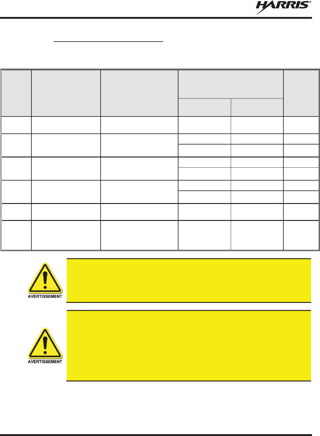
MM-014716-001, Rev. P
32
2.5.4 Monté Antennes (Motocyclette)
Tableau 2-4: Distance latérale sécuritaire minimale recommandée d’une antenne de transmission
branchée sur une radio Motocyclette
RF
BAND
NUMÉRO DE PIÈCE DE
L’ÉLÉMENT DE
L’ANTENNE
DESCRIPTION DE
L’ANTENNE
DISTANCE MINIMALE
RECOMMANDÉE DE L
’
ANTENNE DE
TRANSMISSION POUR LE CORPS
HUMAIN
MAX.
TX
PUISSANCE
(Watts)
ENVIRONNEMENT
CONTRÔLÉ
ENVIRONNEMENT
NON CONTRÔLÉ
VHF
LE-
OM150K.125/TNC
136 to 174 MHz motocyclette-
monture; gain de 2.5
dBd
53 cm 118 cm 20
VHF
AN
-125001-
005 (monture)
avec
AN
-225002-
004 (élément)
136 to 174 MHz; combo
antenne de toit épais e; sans
plan de sol;gain de 2.4
dBd
50 cm — 18
— 50 cm 3.6
UHF
- L
AN
-125001-
005 (monture)
avec
AN
-225003-
005 (élément)
378 à 430 MHz; combo
antenne de toit épais e; sans
plan de sol;gain de 0 dBd;
50 cm — 43
— 50 8.5
UHF - H
AN
-125001-005 (mo
nture)
avec
AN
-225004-
005 (élément)
450 à 505 MHz; combo
antenne de toit épais et; sans
plan de sol; gain de 0
dBd
50 cm — 47
— 50 cm 9.5
800 MHz
LE
-
OM806HDBKTNCDS
800
MHz -
monture; gain de
3.5 dBd 28 cm 72 cm 20
700 or 800
MHz
AN
-125001-
006 (monture)
avec
AN
-225001-
003 (élément)
700/800 MHz; combo
antenne de toit et GPS; point
d’alimentation surélevé, gain
de 3 dBd sans plan de sol
50 cm 50 cm 20
Une radio utilisé dans une installation de motocyclette doit être configuré avec un
niveau de puiss
ance de sortie d'émission inférieur ou égal au maximum TX
Puissance
(Watts
) spécifications énumérées dans le Tableau 2-4 pour la bande de
fréquence
respective
et l'élément antenne / antenne. Reportez-vous au manuel d'installation
de la
radio
pour des informations supplémentaires.
Quand un kit d'installation de moto plus tard, la conception est employée (qui utilise
élément d'antenne UN AN-225001-003 ou 225002-004), le câble coaxial entre la radio
et la base de la monture d'antenne ne peut pas être plus courte que 44 pouces (111,8
cm) . Reportez-vous au manuel d'installation de la radio pour des informations
supplémentaires.
Une radio destinés à une installation non-moto ne doit pas être utilisé dans une
installation de moto sauf se il est reprogrammé par les procédures présentées dans le
Manuel d'installation de la radio.

MM-014716-001, Rev. P
33
2.6 RENSEIGNEMENTS SUR LA FORMATION SUR LA SANTÉ ET LA
SÉCURITÉ AU TRAVAIL
S’assurer que l’exposition physique à l’énergie électromagnétique des RF se situe dans les limites
acceptables de la FCC pour l’utilisation professionnelle. Toujours se conformer aux directives de base
suivantes:
x Le bouton de microphone doit être abaissé seulement lorsque l’on souhaite envoyer un message
vocal.
x La radio doit être utilisée seulement pour les communications nécessaires liées au travail.
x La radio doit être utilisée seulement par du personnel autorisé et formé. Elle ne doit jamais être
utilisée par des enfants.
x Ne tentez pas d’apporter une modification non autorisée à la radio. Des changements ou des
modifications à la radio peuvent causer une interférence nocive ou entraîner un dépassement des
limites d’exposition aux RF de la FCC. Seul le personnel qualifié doit utiliser la radio.
x Utilisez toujours seulement des accessoires autorisés (antennes, haut-parleurs/micros, etc.).
L’utilisation d’accessoires non autorisés peut entraîner un dépassement des exigences de conformité
pour une exposition aux RF de la FCC.
Les renseignements donnés ci-dessus donnent à l’utilisateur les renseignements nécessaires pour le
sensibiliser à l’exposition aux RF et sur ce qu’il faut faire pour s’assurer que cette radio fonctionne dans
les limites d’exposition de la FCC de cette radio.
2.7 DANGERS COURANTS
L'utilisateur de toute radio mobile doit être informé des dangers courants aux
transmissions par des radios de véhicules.
Les dangers éventuels comprennent,
sans toutefois s'y limiter
:
x Atmosphères explosives – De la même manière qu'il est dangereux de faire le plein d'essence d'un
véhicule dont le moteur est en marche, s'assurer que la radio est éteinte (position OFF) avant de faire
le plein d'essence. NE PAS transporter de conteneurs de carburant dans le coffre d'un véhicule si la
radio est montée dans celui-ci.
Les zones avec une atmosphère potentiellement explosive sont souvent, mais pas toujours, clairement
signalés. Éteindre la radio (position OFF) dans toutes les zones avec une atmosphère potentiellement
explosive. Il est rare, mais pas impossible, que la radio ou ses accessoires génère des étincelles.
x Interférences avec les systèmes électroniques de véhicules – Les systèmes électroniques à injection
de carburant, les systèmes électroniques de freinage antidérapage, les systèmes électroniques de
régulateur de vitesse, etc., sont des systèmes pouvant mal fonctionner en raison d'une protection
insuffisante contre l'énergie RF présente lors des transmissions. Si le véhicule est équipe de tels
systèmes, consulter le concessionnaire pour obtenir des informations sur la marque du véhicule et
déterminer si de tels circuits électroniques fonctionnent normalement lorsque le radio émet.
x Détonateurs électroniques – Afin d'éviter toute explosion accidentelle des détonateurs électriques,
NE PAS UTILISER les radios émetteur-récepteur à moins de 305 mètres (1 000 pieds) d'une
opération de dynamitage. Respecter toujours les signes d’extinction des radios émetteur-récepteur
affichés dans les endroits où les détonateurs électriques sont utilisés. (norme OSHA : 1926.900)

MM-014716-001, Rev. P
34
x Énergie des fréquences radio – Pour prévenir toute brûlure ou toute blessure physique connexe
causée par l'énergie des fréquences radio, ne pas faire fonctionner l'émetteur lorsqu'une personne à
l'extérieur du véhicule est située en deçà de la distance minimale sécuritaire de l'antenne, comme
stipulé à la Section 2.5.
x Véhicules alimentés au gaz de pétrole liquéfié (GLP) – L'installation de radios mobiles dans des
véhicules alimentés au gaz de pétrole liquéfié avec un réservoir GLP dans le coffre ou dans tout autre
espace scellé à l'intérieur du véhicule doit être conforme à la norme NFPA 58 de la National Fire
Protection Association. Exigences :
¾ L'emplacement qui abrite la radio doit être isolé et scellé de l'emplacement contenant le réservoir
de GLP et ses raccords.
¾ Des raccords de remplissage extérieurs doivent être utilisés pour le réservoir de GLP.
¾ Le réservoir de GLP doit être pourvu d'une évacuation vers l'extérieur du véhicule
x Véhicules équipés de coussins gonflables – Pour la protection du conducteur et celle des passagers,
éviter d'installer les têtes de commandes de la radio (ou tout autre composant) au-dessus ou à
proximité des zones de déploiement de ces coussins gonflables. Outre les coussins gonflables avant
du conducteur et du passager, certains véhicules peuvent aussi être équipés de coussins gonflables
latéraux. Pour la sécurité des occupants, vérifier l'emplacement de tous les coussins gonflables dans le
véhicule avant d'installer équipement radio.
2.8 RECOMMANDATIONS POUR UNE CONDUITE SÉCURITAIRE
Recommandations principales de l'American Automobile Association (AAA) pour une conduite en toute
sécurité :
x Lire la documentation sur la sécurité d'utilisation de la radio.
x Garder les deux mains sur le volant et ranger le microphone dans son support durant la conduite du
véhicule.
x Effectuer un appel seulement lorsque le véhicule est à l'arrêt.
x Si un appel doit être effectué alors que le véhicule est en mouvement, conduire dans la voie la plus
lente. Les conversations doivent être brèves.
x Si une conversation nécessite la prise de notes ou exige une réflexion plus approfondie, arrêter le
véhicule dans un endroit sûr et poursuivre l'appel.
x Toujours utiliser une radio mobile avec prudence.
MM-014716-001, Rev. P
35
2.9 RÈGLES ET RÉGLEMENTATIONS D'UTILISATION
Les systèmes de radio émetteur-récepteur doivent être utilisés conformément aux règles et
réglementations du gouvernement local, régional ou national.
Aux États-Unis, la radio mobile XG-75M/M7300 doit être utilisée conformément aux règles et
réglementations de la Commission fédérale des communications (FCC). L'opérateur d'une radio émetteur-
récepteur doit être pleinement familiarisé avec les règles qui s'appliquent au fonctionnement d'une radio
de ce type. Le respect de ces règles aide à éliminer la confusion, garantit une utilisation hautement
efficace des canaux radio existants et assure le bon fonctionnement du réseau radio.
Rappels des règles à suivre lors de l'utilisation d'une radio émetteur-récepteur :
x L'interruption de messages de détresse ou d'urgence constitue une violation des règles de la FCC. Le
fonctionnement de la radio est similaire au fonctionnement d'un téléphone « connexion multipoint ».
Par conséquent, toujours écouter avant d'émettre afin de s'assurer que le canal est libre. Les appels
d'urgence sont prioritaires sur tous les autres messages. Si un message d'urgence est en cours de
transmission (pour signaler un incendie ou demander de l'aide à la suite d'un accident, par exemple),
ne pas émettre de messages sauf pour venir en aide.
x La loi fédérale interdit l'utilisation d'un langage obscène ou blasphématoire.
x La loi interdit l'envoi de faux indicatifs d'appel ou de faux messages de détresse ou d'urgence. La
FCC exige que vos conversations soient brèves et s'en tiennent au sujet de l'appel. Pour gagner du
temps, utiliser autant que possible des messages codés.
x L'utilisation de la radio pour l'envoi de messages personnels (sauf en cas d'urgence) constitue une
violation des règles de la FCC. Envoyer des messages essentiels uniquement.
x La loi fédérale interdit la répétition ou la diffusion de toute information entendue via les
communications radio. Les conversations entre les utilisateurs qui partagent un même canal doivent
être traitées comme des messages confidentiels.
x La FCC exige que les utilisateurs s'identifient à certains moments au moyen de leur indicatif d'appel.
Se référer aux règles qui s'appliquent au type particulier d'activités pour la bonne procédure à suivre.
x Aucune modification ou aucun ajustement ne doit être fait à l'équipement, sauf par un technicien
électronique autorisé et certifié.
En vertu de la loi des États
-
Unis, l'utilisation d'un émetteur radio sans licence sur le
territoire américain est punissable d'une amende d'un maximum de 10
000
$, d'un
emprisonnement de deux (2) ans au maximum, ou les deux.
MM-014716-001, Rev. P
36
3. MARINE FREQUENCIES
Refer to Table 3-1: Marine Frequencies for a list of maritime frequencies per United States Coast Guard
(USCG), National Oceanic and Atmospheric Administration (NOAA), and Canadian Department
Fisheries and Oceans, August 2009:
x United States (US)
x International (Intl)
x Canada (CA)
Table 3-1: Marine Frequencies
CHANNEL
FREQUENCY
CHANNEL USAGE
US
INTL
CA
SHIP
(MHZ)
SHORE
(MHZ)
1
1
T: 156.05
R: 160.65
T: 160.65
R: 156.05
International: Public Correspondence, Port Operations
1a
T/R:
156.05
T/R:
156.05
US: Port Operations and Commercial, Vessel Traffic Service (VTS). New
Orleans/Lower Mississippi area.
2
2
T: 156.10
R: 160.70
T: 160.70
R: 156.10
International: Public Correspondence, Port Operations
3
3
T: 156.15
R: 160.75
T: 160.75
R: 156.15
International: Public Correspondence, Port Operations
4
T: 156.20
R: 160.80
T: 160.80
R: 156.20
International: Public Correspondence, Port Operations
4a
T/R:
156.20
T/R:
156.20
Canada: Department Fisheries Ocean (DFO)/Canadian Coast Guard only in
British Columbia coast area. Commercial fishing in east coast area
5
T: 156.25
R: 160.85
T: 160.85
R: 156.25
International: Public Correspondence, Port Operations
5a
5a
T/R:
156.25
T/R:
156.25
US: Port Operations or VTS in Houston, New Orleans and Seattle areas.
6
6
6
T/R:
156.30
T/R:
156.30
US: Intership Safety
International: Intership
Canada: May be used for search and rescue communications between ships
and aircraft.
7
T: 156.35
R: 160.95
T: 160.95
R: 156.35
International: Public Correspondence, Port Operations
7a
7a
T/R:
156.35
T/R:
156.35
US: Commercial
8
8
8
T/R:
156.40
T/R:
156.40
US: Commercial (Intership only)
International: Intership
Canada: Also assigned for intership in the Lake Winnipeg area.
9
9
9
T/R:
156.45
T/R:
156.45
US: Boater Calling. Commercial and Non-Commercial.
International: Intership, Port Operations
Canada: Commercial
- British Columbia coast area.
May be used to communicate with aircraft and helicopters in predominantly
maritime support operations.

MM-014716-001, Rev. P
37
Table 3-1: Marine Frequencies
CHANNEL
FREQUENCY
CHANNEL USAGE
US
INTL
CA
SHIP
(MHZ)
SHORE
(MHZ)
10
10
10
T/R:
156.50
T/R:
156.50
US: Commercial
International: Intership, Port Operations
Canada: Commercial
- British Columbia coast area.
May also be used for communications with aircraft engaged in coordinated
search and rescue and antipollution operations.
11
11
11
T/R:
156.55
T/R:
156.55
US: Commercial. VTS in selected areas.
International: Port Operations
Canada: VTS
- British Columbia coast area.
Also used for pilotage purposes.
12
12
12
T/R:
156.60
T/R:
156.60
US: Port Operations. VTS in selected areas.
International: Port Operations
Canada: VTS
- British Columbia coast area.
Also used for pilotage purposes.
13
13
13
T/R:
156.65
T/R:
156.65
US: Intership Navigation Safety (Bridge-to-bridge). Ships >20m length
maintain a listening watch on this channel in US waters.
International: Intership, Port Operations
Canada: VTS
- British Columbia coast area.
Also used for pilotage purposes.
14
14
14
T/R:
156.70
T/R:
156.70
US: Port Operations. VTS in selected areas.
International: Port Operations
Canada: VTS
- British Columbia coast area.
Also used for pilotage purposes.
15
15
15
T/R:
156.75
T/R:
156.75
US: Environmental (Receive only). Used by Class C Emergency Position-
Indicating Ra
dio Beacons (EPIRBs).
International: Intership, Port Operations
Canada: Port operations and Ship Movement
-
British Columbia coast area.
All operations limited to 1
-watt maximum power. May also be used for on-
board communications.
16
16
16
T/R:
156.80
T/R:
156.80
US: International Distress, Safety and Calling. Ships required to carry radio,
US Coast Guard (USCG), and most coast stations maintain a listening watch
on this channel.
International: International Distress, Safety and Calling
Canada: International Distress, Safety and Calling
17
17
17
T/R:
156.85
T/R:
156.85
US: State Control
International: Intership, Port Operations
Canada: Port operations and Ship Movement
-
British Columbia coast area.
All operations limited to 1 watt maximum power. May als
o be used for on-
board communications.
18
T: 156.90
R: 161.50
T: 161.50
R: 156.90
International: Public Correspondence, Port Operations
18a
18a
T/R:
156.90
T/R:
156.90
US: Commercial
Canada: Towing - British Columbia coast area.
19
T: 156.95
R: 161.55*
T: 161.55*
R: 156.95
International: Public Correspondence, Port Operations
19a
19a
T/R:
156.95
T/R:
156.95
US: Commercial
Canada: DFO/Canadian Coast Guard. Pacific Pilots
-
British Columbia coast
area.

MM-014716-001, Rev. P
38
Table 3-1: Marine Frequencies
CHANNEL
FREQUENCY
CHANNEL USAGE
US
INTL
CA
SHIP
(MHZ)
SHORE
(MHZ)
20
20
20
T: 157.00
R: 161.60
T: 161.60
R: 157.00
US: Port Operations (Duplex)
International: Public Correspondence, Port Operations
Canada: Port operations only with 1 watt maximum power.
20a
T/R:
157.00
T/R:
157.00
US: Port Operations
21
T: 157.05
R: 161.65*
T: 161.65*
R: 157.05
International: Public Correspondence, Port Operations
21a
21a
T/R:
157.05
T/R:
157.05
US: US Coast Guard only
Canada: DFO/Canadian Coast Guard only.
21b
- -
T/R:
161.65
22
T: 157.10
R: 161.70
T: 161.70
R: 157.10
International: Public Correspondence, Port Operations
22a
22a
T/R:
157.10
T/R:
157.10
US: Coast Guard Liaison and Maritime Safety Information Broadcasts.
Broadcasts announced on channel 16.
Canada: For communications between Canadian Coast Guard and non
-
Canadian Coast Guard stations only.
23
23
T: 157.15
R: 161.75
T: 161.75
R: 157.15
International: Public Correspondence, Port Operations
23a
T/R:
157.15
T/R:
157.15
US: US Coast Guard only
23b
- -
T/R:
161.75
Canada: Continuous Marine Broadcast (CMB) service.
24
24
24
T: 157.20
R: 161.80
T: 161.80
R: 157.20
US: Public Correspondence (Marine Operator)
International: Public Correspondence, Port Operations
25
25
25
T: 157.25
R: 161.85
T: 161.85
R: 157.25
US: Public Correspondence (Marine Operator)
International: Public Correspondenc
e, Port Operations
Canada: Also assigned for operations in the Lake Winnipeg area.
25b
T/R:
161.85
26
26
26
T: 157.30
R: 161.90
T: 161.90
R: 157.30
US: Public Correspondence (Marine Operator)
International: Public Correspondence, Port Operations
27
27
27
T: 157.35
R: 161.95
T: 161.95
R: 157.35
US: Public Correspondence (Marine Operator)
International: Public Correspondence, Port Operations
28
28
28
T: 157.40
R: 162.00
T: 162.00
R: 157.40
US: Public Correspondence (Marine Operator)
International: Public Correspondence, Port Operations
28b
- -
T/R:
162.00
Canada: Continuous Marine Broadcast (CMB) service.
60
60
T: 156.025
R: 160.625
T: 160.625
R: 156.025
International: Public Correspondence, Port Operations
61
T: 156.075
R: 160.675
T: 160.675
R: 156.075
International: Public Correspondence, Port Operations
61a
61a
T/R:
156.075
T/R:
156.075
Canada: DFO/Canadian Coast Guard only in British Columbia coast area.

MM-014716-001, Rev. P
39
Table 3-1: Marine Frequencies
CHANNEL
FREQUENCY
CHANNEL USAGE
US
INTL
CA
SHIP
(MHZ)
SHORE
(MHZ)
62
T: 156.125
R: 160.725
T: 160.725
R: 156.125
International: Public Correspondence, Port Operations
62a
T/R:
156.125
T/R:
156.125
Canada: DFO/Canadian Coast Guard only in British Columbia coast area.
63
T: 156.175
R: 160.775
T: 160.775
R: 156.175
International: Public Correspondence, Port Operations
63a
63a
T/R:
156.175
T/R:
156.175
US: Port Operations and Commercial, VTS. New Orleans/Lower Mississippi
area.
Canada: Tow Boats - British Columbia coast area.
64
64
T: 156.225
R: 160.825
T: 160.825
R: 156.225
International: Public Correspondence, Port Operations
64a
64a
T/R:
156.225
T/R:
156.225
Canada: Commercial fishing only.
65
T: 156.275
R: 160.875
T: 160.875
R: 156.225
International: Public Correspondence, Port Operations
65a
65a
T/R:
156.275
T/R:
156.275
US: Port Operations
Canada: Search and rescue and antipollution operations on the Great Lakes.
Towing on the Pacific Coast. Port operations only in the St.
Lawrence River
areas with 1
watt maximum power. Intership in inland Manitoba,
Saskatchewan, and Alberta areas.
66
T: 156.325
R: 160.925
T: 160.925
R: 156.325
International: Public Correspondence, Port Operations
66a
66a
T/R:
156.325
T/R:
156.325
US: Port Operations
Canada: Port operations only in the St.
Lawrence River/Great Lakes areas
with 1 watt maximum power. 1
watt marina channel - British Colu
mbia coast
area.
67
67
67
T/R:
156.375
T/R:
156.375
US: Commercial. Used for Bridge-to-bridge communications in lower Miss.
River. Intership only.
International: Intership, Port Operations
Canada: May also be used for communications with aircraft engaged
in
coordinated search and rescue and antipollution operations. Commercial
fishing only in east coast and inland Manitoba, Saskatchewan, and Alberta
areas. Pleasure craft - British Columbia coast area.
68
68
68
T/R:
156.425
T/R:
156.425
US: Non-Commercial
International: Port Operations
Canada: For marinas, yacht clubs and pleasure craft.
69
69
69
T/R:
156.475
T/R:
156.475
US: Non-Commercial
International: Intership, Port Operations
Canada: Commercial fishing only
- east coast area.
Pleasure craft - British Columbia coast area.
70
70
70
T/R:
156.525
T/R:
156.525
US: Digital Selective Calling (voice communications not allowed)
International: Digital selective calling for distress, safety and calling
Canada: Digital selective calling for distress, safety and calling
71
71
71
T/R:
156.575
T/R:
156.575
US: Non-Commercial
International: Port Operations
Canada: Ship Movement
- British Columbia coast area.Marinas and yacht
clubs - east coast and on Lake Winnipeg.

MM-014716-001, Rev. P
40
Table 3-1: Marine Frequencies
CHANNEL
FREQUENCY
CHANNEL USAGE
US
INTL
CA
SHIP
(MHZ)
SHORE
(MHZ)
72
72
72
T/R:
156.625
T/R:
156.625
US: Non-Commercial (Intership only)
International: Intership
Canada: May be used to communicate with aircraft and helicopters in
predominantly maritime support operations.
Pleasure craft - British Columbia coast area
73
73
73
T/R:
156.675
T/R:
156.675
US: Port Operations
International: Intership, Port Operations
Canada: May also be used for communications with aircraft engaged in
coordinated search and rescue and antipollution operations. Commercial
fishing only in east coast and inland Manitoba, Saskatchewan, and Alberta
areas.
74
74
74
T/R:
156.725
T/R:
156.725
US: Port Operations
International: Port Operations
Canada: VTS and Ship Movement British Columbia coast area.
75
75
75
T/R:
156.775
T/R:
156.775
International: Port Operations
Canada: Simplex port operatio
n, ship movement and navigation related
communication only.
1 watt maximum.
76
76
76
T/R:
156.825
T/R:
156.825
International: Port Operations
Canada: Simplex port operation, ship movement and navigation related
communication only.
1 watt maximum.
77
77
77
T/R:
156.875
T/R:
156.875
US: Port Operations (Intership only)
International: Intership
Canada: Pilotage
-
British Columbia coast area; 25 watts. Port operations only
in the St. Lawrence River/Great Lakes areas with 1 watt maximum power.
78
T: 156.925
R: 161.525
T: 161.525
R: 156.925
International: Public Correspondence, Port Operations
78a
78a
T/R:
156.925
T/R:
156.925
US: Non-Commercial
Canada: Fishing Industry - British Columbia coast area.
79
T: 156.975
R: 161.575
T: 161.575
R: 156.975
International: Public Correspondence, Port Operations
79a
79a
T/R:
156.975
T/R:
156.975
US: Commercial. Non-Commercial in Great Lakes only
Canada: Fishing Industry - British Columbia coast area.
80
T: 157.025
R: 161.625
T: 161.625
R: 157.025
International: Public Correspondence, Port Operations
80a
80a
T/R:
157.025
T/R:
157.025
US: Commercial. Non-Commercial in Great Lakes only
Canada: Fishing Industry - British Columbia coast area.
81
T: 157.075
R: 161.675
T: 161.675
R: 157.075
International: Public Correspondence, Port Operations
81a
81a
T/R:
157.075
T/R:
157.075
US: US Government only - Environmental protection operations
Canada: DFO/Canadian Coast Guard use only.
82
T: 157.125
R: 161.725
T: 161.725
R: 157.125
International: Public Correspondence, Port Operations
82a
82a
T/R:
157.125
T/R:
157.125
US: US. Government only
Canada: DFO/Canadian Coast Guard use only.

MM-014716-001, Rev. P
41
Table 3-1: Marine Frequencies
CHANNEL
FREQUENCY
CHANNEL USAGE
US
INTL
CA
SHIP
(MHZ)
SHORE
(MHZ)
83
T: 157.175
R: 161.775
T: 161.775
R: 157.175
International: Public Correspondence, Port Operations
83a
83a
T/R:
157.175
T/R:
157.175
US: US Coast Guard only
Canada: DFO/Canadian Coast Guard and other Government agencies.
83b
- -
T/R:
161.775
84
84
84
T: 157.225
R: 161.825
T: 161.825
R: 157.225
US: Public Correspondence (Marine Operator)
International: Public Correspondence, Port Operations
85
85
85
T: 157.275
R: 161.875
T: 161.875
R: 157.275
US: Public Correspondence (Marine Operator)
International: Public Correspondence, Port Operations
86
86
86
T: 157.325
R: 161.925
T: 161.925
R: 157.325
US: Public Correspondence (Marine Operator)
International: Public Correspondence, Port Operations
87
87
87
T: 157.375
R: 161.975
T: 161.975
R: 157.375
US: Automatic Identification System duplex repeater
International: Port Operations
Canada: Port operation and ship movement
- east coast area.
Pleasure craft - British Columbia coast area.
87a
T/R:
157.375
T/R:
157.375
US: Public Correspondence (Marine Operator)
87b
T/R:
161.975
T/R:
161.975
Canada: Automatic Ship Identification and Surveillance System.
88
88
T: 157.425
R: 162.025
T: 162.025
R: 157.425
US: Commercial, Intership only.
International: Port Operations
Canada: Port operation and ship movement - British Columbia coast area.
88a
T/R:
157.425
T/R:
157.425
US: Commercial, Intership only.
Canada: Automatic Ship Identification and Surveillance System.
88b
T/R:
162.025
T/R:
162.025
WX1
WX1
R: 162.55
WX2
WX2
R: 162.4
WX3
WX3
R: 162.475
WX4
R: 162.425
WX5
R: 162.45
WX6
R: 162.5
WX7
R: 162.525

MM-014716-001, Rev. P
42
4. PRODUCT DESCRIPTION
The XG-75M/M7300 mobile is a state-of-the-art radio designed to meet the critical demands of its users.
The XG-75M/M7300 mobile supports multiple operating modes, including OpenSky® digital trunked
operation (700/800 MHz radios only), Enhanced Digital Access Communications System (EDACS®) or
ProVoiceTM trunked modes, P25 digital trunked mode, P25 digital conventional mode, and analog
conventional mode.
The XG-75M mobile radio is essentially an M7300 mobile radio running XGP radio software/firmware.
Otherwise, an XG-75M radio is identical to a similar-RF-banded M7300 radio.
The optional Global Positioning System (GPS) receiver module can provide standard GPS formatted data
over the air for vehicle tracking systems.
Data Encryption Standard (DES) and the optional Advanced Encryption Standard (AES) are available for
maximum communications security.
The XG-75M/M7300 radio uses the CH-721 Control Head which is available in two models: System and
Scan. The display is designed to maximize readability and ease of use. The CH-721 utilizes a 3-line 12-
character alphanumeric display with large buttons, volume knob, and channel knob, providing a user-
friendly interface.
The CH-721 control head can be mounted with the radio (Front Mount) or it can be mounted and operated
remotely. For remote mount installations configured with a CH-721 control head, all normal radio
operations and interfaces can be handled via the control head connected to the radio unit via a 3-wire
Controller Area Network (CAN) cable. Two control heads may be attached to a radio. Each control head
provides a serial access point for data and any one (only one at a time) can be connected to a data device
such as a personal computer.
Where multiple control heads are connected or where a dash-mount radio is installed with an additional
remote control head, the following features are available from each position:
x Outgoing voice calls can be initiated. Either control head can initiate a call but only one can talk at a
time. The other connected control head hears both sides of the conversation.
x Incoming and outgoing audio can be heard. (Outgoing audio is not broadcast at the source position.)
x Independent audio control is available.
x Radio settings such as talk group, scan mode etc., can be controlled. (Any connected control head can
override the radio settings of another connected control head.)
x Comfort settings, such as volume and display brightness that are applicable to the individual control
head can be adjusted and cannot be overridden by another control head.
x An optional intercom function is available between control units. Audio is broadcast to ALL
connected control heads.

MM-014716-001, Rev. P
43
5. CHANGE OPERATING MODE (700/800 MHZ RADIOS
ONLY)
5.1 CHANGE FROM OTP MODE
To change from OTP operating mode to EDACS, Conventional, and P25 (ECP/XGP) Modes:
1. Use , CLEAR/CLR, or OPTION/OPT to cycle through the menu until the “App Mode”
appears in the bottom line of the display.
2. Use to choose an available mode. Press MENU and confirm (Y/N) with and press
MENU again.
3. Press the MENU button to confirm.
Or
Preset button C can be configured via programming to reboot the radio into a particular application mode.
Or
Quick Button command 1# transitions the radio to ECP/XGP mode. If ECP/XGP mode is not loaded in
the radio, the radio displays “No App.”
5.2 CHANGE TO OTP MODE
1. Use to scroll through available systems until OpenSky is displayed.
2. The radio transitions to OTP mode.
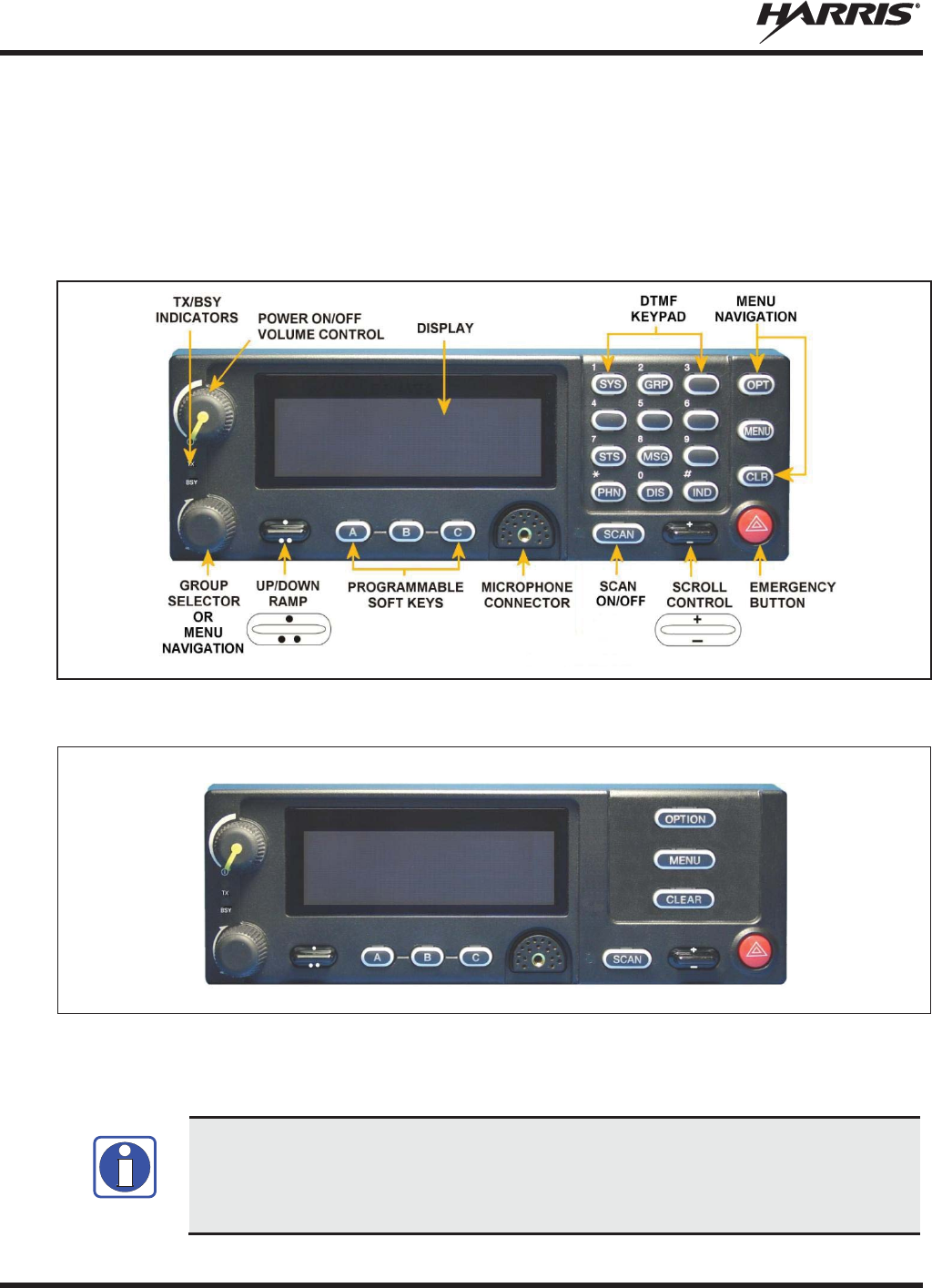
MM-014716-001, Rev. P
44
6. OPENSKY OPERATION (700/800 MHZ RADIOS ONLY)
6.1 CH-721 FRONT PANEL COMPONENTS
The front panel of the control head includes a dot matrix display, controls for menu navigation, an
emergency button, three pre-set buttons, a Power On-Off/Volume Control knob, and a microphone
connector. In addition, the system model control head features a DTMF keypad (Figure 6-1).
Figure 6-1: System Model
Figure 6-2: Scan Model
The buttons on the front panel are backlit for operation in a low ambient light level such as nighttime
operation. Some buttons also flash to provide feedback of various operating conditions.
Button function may vary depending upon radio programming. Any non
-
DTMF button
can be configured to various functions via the at**chkeymap command. Refer to the AT
command manu
al (MM-016649-001) for all possible events. Table 6-1
describes the
default configuration.
NOTE
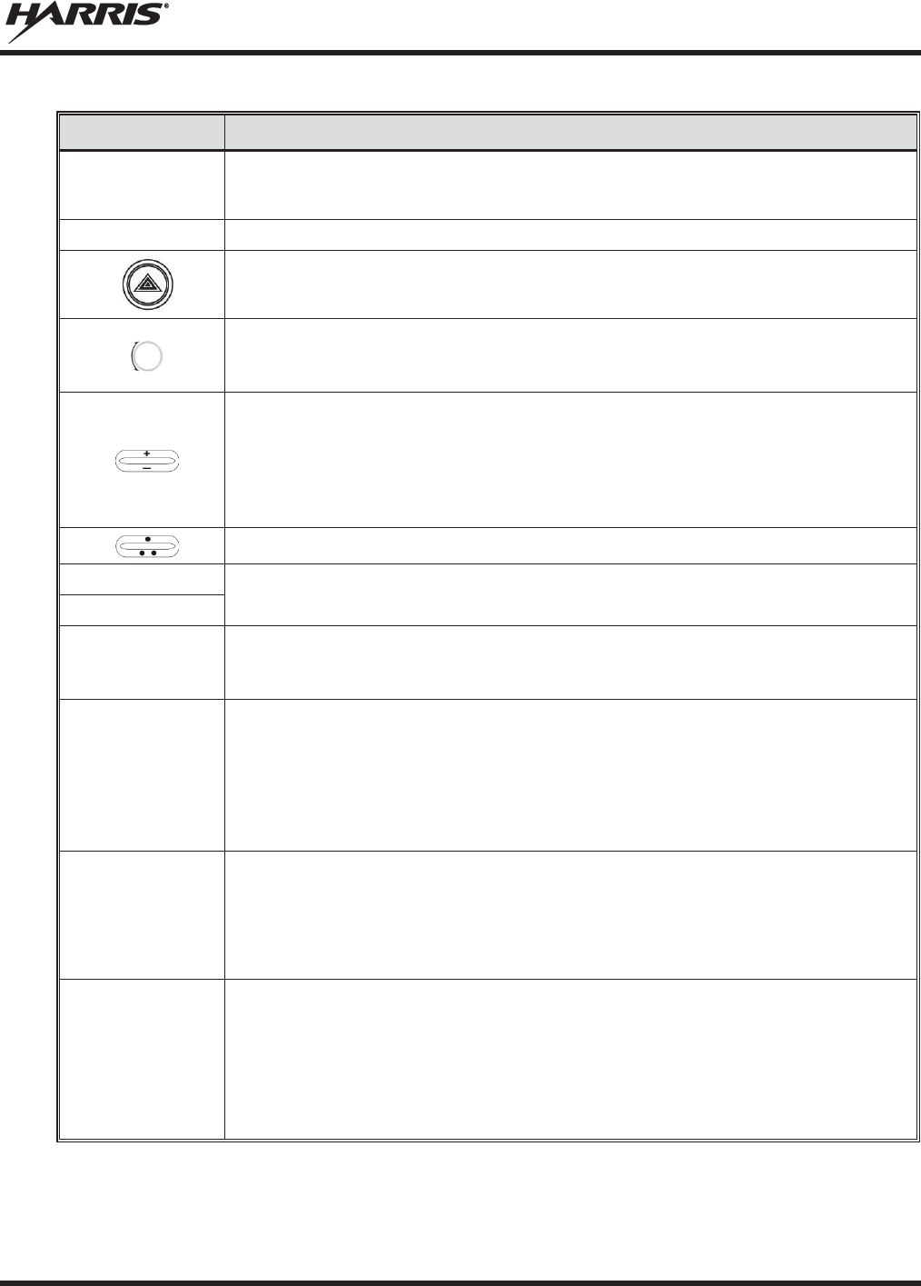
MM-014716-001, Rev. P
45
Table 6-1: Front Panel Default Controls and Functions
PART
FUNCTION
Power
On-
Off/Volume Control
K
nob
Turn knob clockwise to power on the radio and increase volume.
Turn counter
-clockwise to decrease volume and power off the radio.
Mic
Connection
Connection for hand
-held, hands-free, speaker-mic, headset, or programming cable.
If enabled through programming, the emergency button sends an emergency and opens
voice communication on the currently selected talk group or the default emergency talk group
(depending upon how the system is defined).
While in the dwell display, scro
lls through available talk groups.
Scrolls through selections within the active menu (available talk groups, preprogrammed
speed dial numbers, canned alert messages, etc.).
IF ENABLED VIA PROGRAMMING
, while in the dwell display, scrolls through availabl
e talk
group
.
Scrolls through selections within the active menu (available talk groups, preprogrammed
speed dial numbers, canned alert messages, etc.).
Or
Increases and decreases the display brightness.
IF ENABLED VIA PROGRAMMING
, scrolls through available menu items.
OPT/OPTION
Scrolls through available menu items.
CLR/CLEAR
MENU
Press to activate the current selection. In some cases, this is not necessary as the last
selection automatically activate
s after a short period.
Also exits Stealth Mode
.
Display Area
Menu selections and messages.
Network Connectivity icon.
RSSI Indicator.
Current Volume Level icon.
Volume represented numerically within the display (0 = Muted, 40 = Loudest).
User may select which one of several dwell displays the radio u
ses.
Pre-
Set Buttons
A, B, & C
These buttons are used to store and recall user-selectable parameters such as scan mode,
selected profile, selected talk group, and priority talk group. Different parameters can be
stored at each of the three different pre
-set buttons.
Preset button C can be configured via programming to reboot the radio into a particular
application mode. Contact your system administrator to determine if this feature is enabled in
your radio.
SCAN
Toggles the Scan Mode ON/OFF.
x
If the Scan Mode is Normal and the Scan Mode is toggled off
, when the Scan Mode is
toggled On the Scan Mode is set to Normal.
x
If the Scan Mode is Fixed and the Scan Mode is toggled off, when the Scan Mode is
toggled On the Scan Mode is set to Fixed.
x
If the Scan Mode is off
when the radio boots up when the Scan Mode is toggled On the
Scan Mode is set to Normal.

MM-014716-001, Rev. P
46
6.2 POWER UP AND VOLUME CONTROL
6.2.1 Power Up
1. Rotate the Power On-Off/Volume Control knob clockwise to power on the radio. The display
illuminates when the radio powers up.
2. Wait for the power-up sequence to complete, which takes approximately ten (10) seconds.
During this time, if enabled for auto registration, the radio is provisioned with a customized user
personality designed for the user’s specific needs by the OpenSky network administrator.
If this personality contains encrypted talk groups or if the user is authorized for, and intends to use,
manual encryption, User Login must be performed unless the radio has been programmed to auto-
login. This requires a system model control head so that the User ID and password can be entered.
3. When provisioning is complete, the radio displays the Dwell Display.
If User Login is required, the bottom line of the Dwell Display flashes the message “Pls Login.”
6.2.2 Volume Control
Turn the Power On-Off/Volume Control knob clockwise to increase the volume and counter-clockwise to
decrease the volume. The radio sounds a tone to indicate the current volume level.
6.3 SELF-TEST
After power-up, the XG-75M/M7300 radio undergoes a multi-function automatic registration procedure.
As many as sixteen (16) possible radio profiles are downloaded to the radio from the network in response
to the User’s ID.
6.4 LOGIN TO THE NETWORK
Login occurs either automatically (auto registration) if the radio has a valid registration or, if enabled and
authorized for encryption (Section 6.32), requires the user to enter a User ID and password.
If encryption is enabled and authorized on the radio, the user is prompted to “Pls Login” with the *1 login
command, a User ID, and password [System Model Control Head required].
1. Press *1 (Login command).
2. Enter the full 10-digit User ID.
3. Press the # key.
4. Enter the password.
x If the radio is configured for alpha-numeric passwords and the password has consecutive
duplicate numbers (“MES33” for example), enter # between the consecutive duplicate numbers
so the radio does not interpret the entry as a letter (“D” in this example).
x If the radio is configured for numeric-only passwords, do not enter # between duplicated
numbers.
5. Press the # key twice for alpha-numeric passwords or once for numeric only passwords.
The User ID may be remembered from the previous login. (Refer to Section 6.5 for further details
regarding log off commands.) The password is established before the radio is put into operation. Contact
the local OpenSky network administrator for more information.
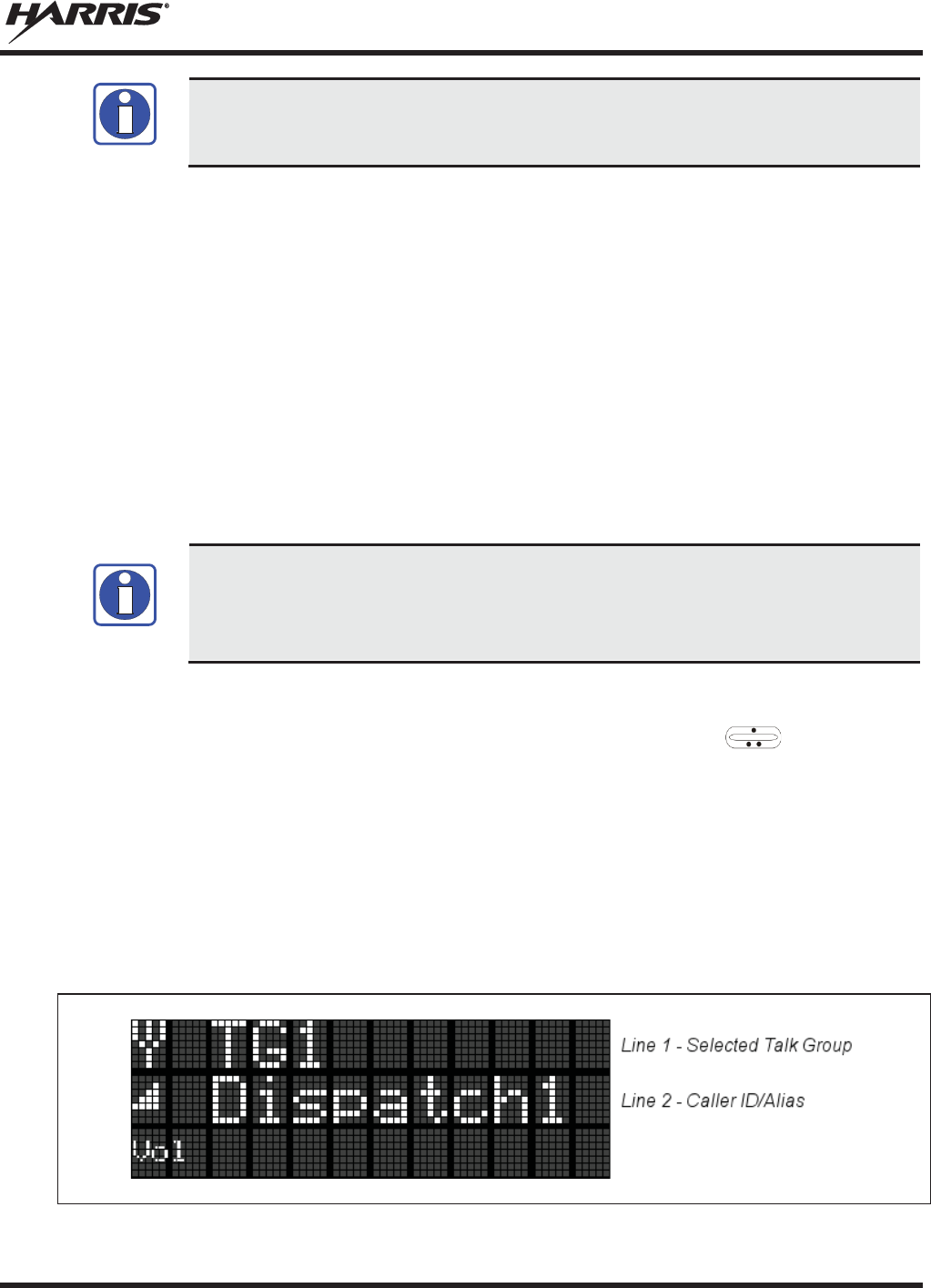
MM-014716-001, Rev. P
47
If necessary, contact radio system administration personnel for login assistance and/or
radio
-specific login instructions.
6.5 LOG OFF THE NETWORK
The *0## command de-registers the radio. Typically, this is automatically performed when powering
down the radio. Using this method, the User ID is remembered by the radio so only the password is
needed at next login. Manually log off by pressing *0## (requires System Model).
6.6 TURN THE RADIO OFF
To turn the radio off, rotate the Power On-Off/Volume Control knob counter-clockwise. In multiple
control head installations, turning off the last powered-up control head also automatically turns off the
radio.
If enabled via programming, several user-selected radio settings (i.e., scan mode, pre-set buttons, and side
tone levels) are maintained for the next operational session. At the next radio power-up, maintained
settings automatically restore, along with the network personality settings. In multiple control head
installations, settings are maintained for each control head position.
If power is abruptly disconnected from the radio prior to executing the correct turn-off
procedure, user
-selected radio settings and last-
tuned channel information are lost. This
can extend the time required for the radio to register with the network upon the
subsequent power
-up.
6.7 MENU DISPLAY AND CONTROL AREA
Following power-up, the radio display shows the default talk group (Figure 6-3). , OPT/OPTION,
or CLR/CLEAR changes the display to the next available menu. In many cases, the dwell display
automatically re-appears after no menu buttons are pressed for a short period of time (between 10 and 30
seconds). For some menus such as the GPS and User ID menus, this does not occur unless the menu
up/down buttons are pressed.
When the dwell display is active, it changes to reflect the current profile, received talk group/caller ID
(when available), or channel if the channel menu is enabled. The second line of dwell menu changes
when the user presses the MENU button.
The radio’s display is highly interactive. It responds in the top and bottom text lines as the user presses
the menu buttons to scroll through the menu loop and the entries for each menu.
Figure 6-3: Typical Display
NOTE
NOTE
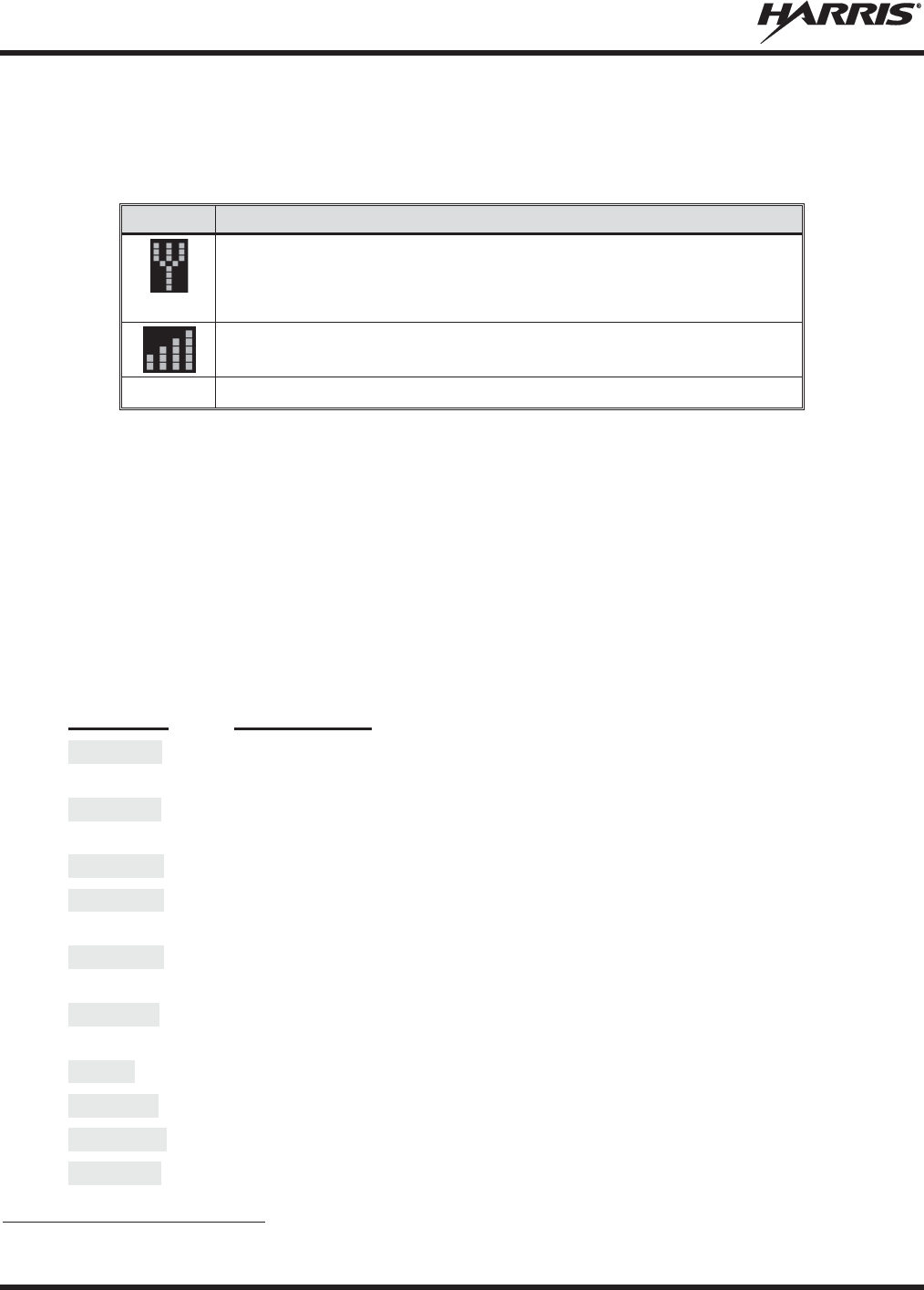
MM-014716-001, Rev. P
48
6.8 RADIO STATUS ICONS
Status Icons indicate the various operating characteristics of the radio. The icons show operating modes
and conditions (see Table 6-2). The location of icons on the display may vary depending on configuration.
Table 6-2: Icons and Descriptions
ICON
DESCRIPTION
Antenna
Indicates
data registration.
Volume bars
– above VOL text
indicates relative volume level.
RSSI indicator appears next to the Antenna icon.
6.9 DWELL DISPLAY
When not engaged in menu selection, the first two lines of the display default to the user-defined display,
known as the “dwell display.” The top line indicates the currently selected talk group. The second line
displays the currently selected profile, caller ID/alias2, received talk group, and current channel name.
Press the MENU button to scroll through and view one of these second line options.
6.10 ERROR MESSAGES
This section lists and describes the error messages that may be displayed by the XG-75M/M7300 during
OpenSky operation.
MESSAGE
DESCRIPTION
NOAUT01
Unspecified MDIS error. If condition persists in strong signal conditions, contact
your system administrator.
MDENIED
Unspecified MDIS error. If condition persists in strong signal conditions, contact
your system administrator.
UNAUTH3
Unauthorized IP. The radio network ID has not been added to network.
UNAUTH4
Bad authentication. If condition persists in strong signal conditions, contact your
system administrator.
UNAUTH5
Unsupported authentication. If condition persists in strong signal conditions, contact
your system administrator.
MDISBSY
The MDIS
is busy. If condition persists in strong signal conditions, contact your
system administrator.
DUP IP
Duplicate IP.
BADIKEY
Invalid infrastructure public key sequence number (IPKSN).
BADEKEY
Invalid end-system public key sequence number (EPKSN).
UNK M
ES
Unknown mobile end system (MES). If condition persists in strong signal conditions,
contact your system administrator.
2 Alias is a logical ID name such as “J_Smith.” The name corresponds to a user ID such as 003-542-0001.

MM-014716-001, Rev. P
49
MESSAGE
DESCRIPTION
NOAUT05
MDIS failed mutual authentication. If condition persists in strong signal conditions,
contact your system administrator.
BAD
MDIS
MDIS failed mutual authentication. If condition persists in strong signal conditions,
contact your system administrator.
MDS BSY
MDIS busy – retry.
UNK DOM
Unknown home domain. If condition persists in strong signal conditions, contact
your system administrator.
KEYSYNC
Mismatched key sequence number.
UNK ALG
Unknown/unsupported encryption algorithm.
BADSIZE
Unsupported MDIS key size.
NOAUT11
MES failed data mutual authentication. If condition persists in strong signal
conditions, contact your system administrator.
NOAUT12
No response from MDIS. If condition persists in strong signal conditions, contact
your system administrator.
NOREPLY
No SME response from MDIS. If condition persists in strong signal conditions,
contact your system administrator.
VDENIED
Unspecified VNIC error. If condition persists in strong signal conditions, contact
your system administrator.
BAD VID
Invalid voice user ID. Check User ID. If correct, contact your system administrator.
HOM DWN
The Home VNIC is down. Retry. If error continues, contact your system
administrator.
SRV BSY
The serving VNIC is busy (congested).
MAX USR
The maximum users are already registered with the specified user ID. OpenSky
allows one User ID to log onto the network using up to three different radios. Use
*0## command or power down one of the other radios to de-register the radio.
NAS BSY
The system cannot provision MES because of an administrative process.
NOAUTHM
The MES failed voice mutual authentication.
If a valid radio displays th
is error,
contact TAC.
NOSUPRT
The MES cannot support the required provision. If condition persists in strong signal
conditions, contact your system administrator.
NOAUTHV
VNIC does not support or failed mutual authentication.
If condition persists in st
rong
signal conditions, contact your system administrator.
PLS LOGIN
If enabled and auth
orized for encryption
, the radio requires the user to enter a User
ID and password if not programmed to auto-login. Login with the keypad.
BAD PWD
An invalid password has been entered. Verify the password and re-enter.
OVER_TEMP
The radio may be too hot. The radio cease
s
transmitting if it exceeds an operational
temperature threshold. Let the radio cool before attempting to transmit. Report this
failure to authorized technician.

MM-014716-001, Rev. P
50
MESSAGE
DESCRIPTION
No App
ECP/XGP mode is unavailable (not programmed).
NO PRIV
Missing required privilege.
NO SYNC
No forward
-
channel sync (weak or no coverage). If condition persists in strong signal
conditions, contact your system administrator.
No Access
Incoming encrypted voice cannot be decrypted. If condition persists in strong signal
conditions, contact your system administrator.
NO REG
Not registered with MDIS, VNIC, or both.
Locked Out
Another control head is actively using the user interface.
DISABLED
Function disabled (e.g., function invalid in current context).
6.11 PERSONALITY
As illustrated in Figure 6-4, a personality defines the profiles and talk groups available to the user. It is
the structuring of a collection of profiles and privileges established by the OpenSky network administrator
to provide the user with a comprehensive set of profiles to communicate effectively with the necessary
talk groups or individuals.
Personalities are stored on the network and downloaded over-the-air to the radio. This process is called
“provisioning.” Provisioning occurs at radio power-up and at user log-in. Each personality can contain up
to sixteen (16) profiles and each profile can contain up to sixteen talk groups.
6.11.1 Profiles
As stated above, each profile can contain up to sixteen (16) talk groups. A profile also defines the radio’s
emergency behavior. All transmissions are made on the selected talk group (displayed on the top line of
the dwell display). The user can change the selected talk group to any of the other talk groups within the
profile.
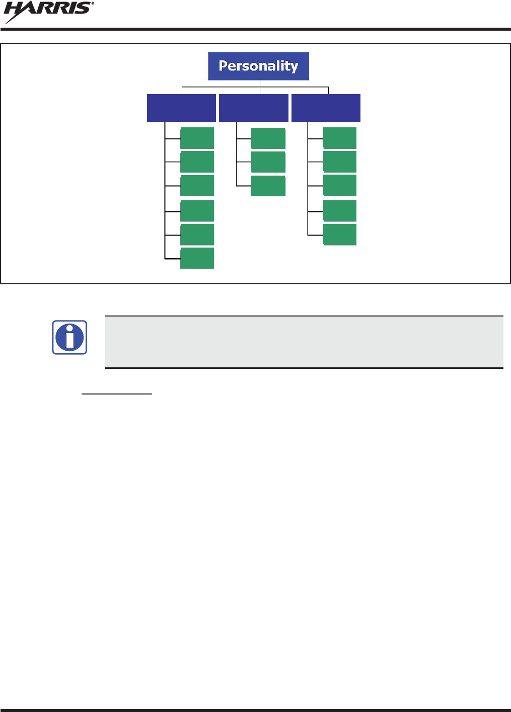
MM-014716-001, Rev. P
51
Figure 6-4: Personality Structure Example
If Global Profile is enabled by the system administrator, the number of available talk
groups to sc
an doubles.
6.11.2 Talk Groups
A talk group represents a set of users that regularly need to communicate with one another. There can be
any number of authorized users assigned to a talk group. Talk groups are established and organized by the
OpenSky network administrator. An OpenSky talk group is similar to a channel within a conventional FM
radio system.
TG a
TG b
TG c
TG x
TG y
TG z
TG d
TG e
TG f
TG a
TG d
TG g
TG h
TG i
TG = Talk Group
Profile 1
Profile 2
Profile 3
NOTE

MM-014716-001, Rev. P
52
6.12 ALERT TONES
The XG-75M/M7300 radio also provides audible Alert Tones or “beeps” to indicate the various operating
conditions (see Table 6-3).
Table 6-3: XG-75M/M7300 OpenSky Mode Alert Tones
NAME
TONE
DESCRIPTION
Call Queued
1 low tone/2 high tones
Call queued for processing.
Call Denied
3
short beeps
Radio is out of coverage area or requested talk group
is active.
Grant (or Go
-
Ahead)
1
short beep
Sounds when resources become available for a call
request placed in the queue (if enabled) upon channel
access
.
If the radio roams to another site while transmitting,
then it aut
o rekeys and begins
transmitting on that
tower. It gives a second grant tone to let the user
know they have roamed.
Priority
Bump
1 short tone
Stopped current incoming call in favor of higher-
priority incoming call.
Call Removed
1
long low-
pitched tone
Notifies the user access to the channel has been lost
(out of coverage area or pre
-empted by higher-
priority
call).
Selective Alert
Received
1 short tone, 2 short
beeps, 1 short tone
Only played once to indicate a selective alert has
been received.
Emergency Tone
3
long tones
Sounds when an emergency is declared
.
Emergency
Cleared
1
long low-
pitched tone
Sounds when an emergency is cleared
.
Volume
1 short tone
Reflects current volume level.
Selective Call Ring
A
ringing tone similar to a
telephone
Ringing is repeated every four seconds until the
call is accepted or rejected by the radio being
called or until the network drops the call if
unanswered after one minute.
PSTN Ring
1
medium-pitch
repeating
tone
Two ring tone - one generated by the radio when
there is an incoming telephone call or an
outgoing telephone call attempt is waiting for the
telephone interconnect gateway equipment to
dial the Public Switched Telephone Network
(PSTN). The second ring tone sounds when the
gateway equipment has dialed the number.
Roam
2
short tones, 1 high-
pitched and 1
low-
pitched
Sounds when the radio transitions from one base
station site to another while transmitting voice.
Out of Range
Tri
-tone beep
If enabled via programming, sounds when the
radio is not
within operational range with base
station.
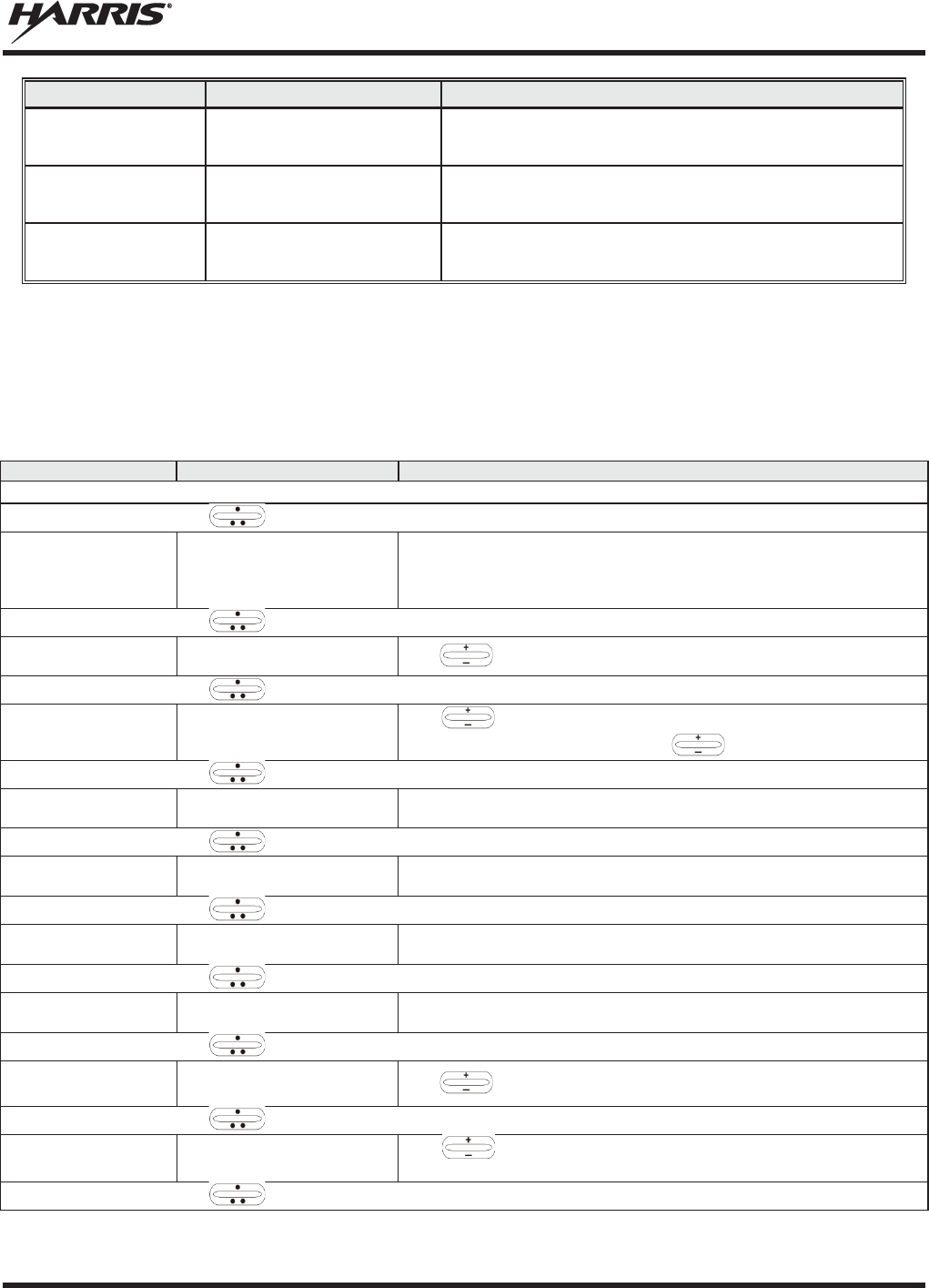
MM-014716-001, Rev. P
53
NAME
TONE
DESCRIPTION
Priority Bump
Single medium mid
-
pitched tone.
Sounds when the current received call is
preempted by a higher priority call.
Site Found Tone
Three short high
-
pitched
tones
.
Sounds when the selected site is found using the
Site Lock Menu.
Site Not Found
Tone
Three short high
-
pitched
tones.
Sounds when the selected site is not found using
the Site Lock Menu.
6.13 BASIC MENU STRUCTURE
Table 6-4 illustrates the basic XG-75M/M7300 OpenSky menu structure. Menu items vary depending
upon system programming, radio hardware, and optional configurations. All menus except the dwell
display menu can be turned off by network administration personnel.
Table 6-4: Basic Menu Structure
MENU NAME
RADIO DISPLAYS
USAGE NOTES
To/From Dwell Display
, CLR, or OPT
Engineering Display
bit-error rates,
RSSI data, sync status,
current channel and
registration status
Displays radio system connection data. For engine
ering use.
, CLR, or OPT
Silent Emergency
“SilentEmerg”
Use
to toggle Silent Emergency “On” or “Off.”
, CLR, or OPT
Operating Mode
“App Mode”
Use
to choose an available mode (OTP, ECP/XGP
, or OCF).
Press MENU and confirm (Y/N) with and press MENU again.
, CLR, or OPT
GPS Fix “GPS Fix”
Radio’s current GPS latitude and longitude position scrolls across top
line of the display. Applies to GPS-equipped radios only.
, CLR, or OPT
User ID “User ID”
User’s identification/name scrolls across top line of the display (if
programmed).
, CLR, or OPT
IP Address “IP Address”
Radio’s Internet Protocol (IP) address scrolls across top line of the
display.
, CLR, or OPT
Station Identification
“Station ID”
Station’s identification/name scrolls across top line of the display (if
programmed).
, CLR, or OPT
Stealth Mode “StealthMenu”
Use
to turn Stealth Mode “On.”
, CLR, or OPT
Treble Level “Treble Menu”
Use
to choose speaker/headset treble level (LOW, MEDIUM,
MEDHIGH, or HIGH). Press Select to return to dwell display.
, CLR, or OPT
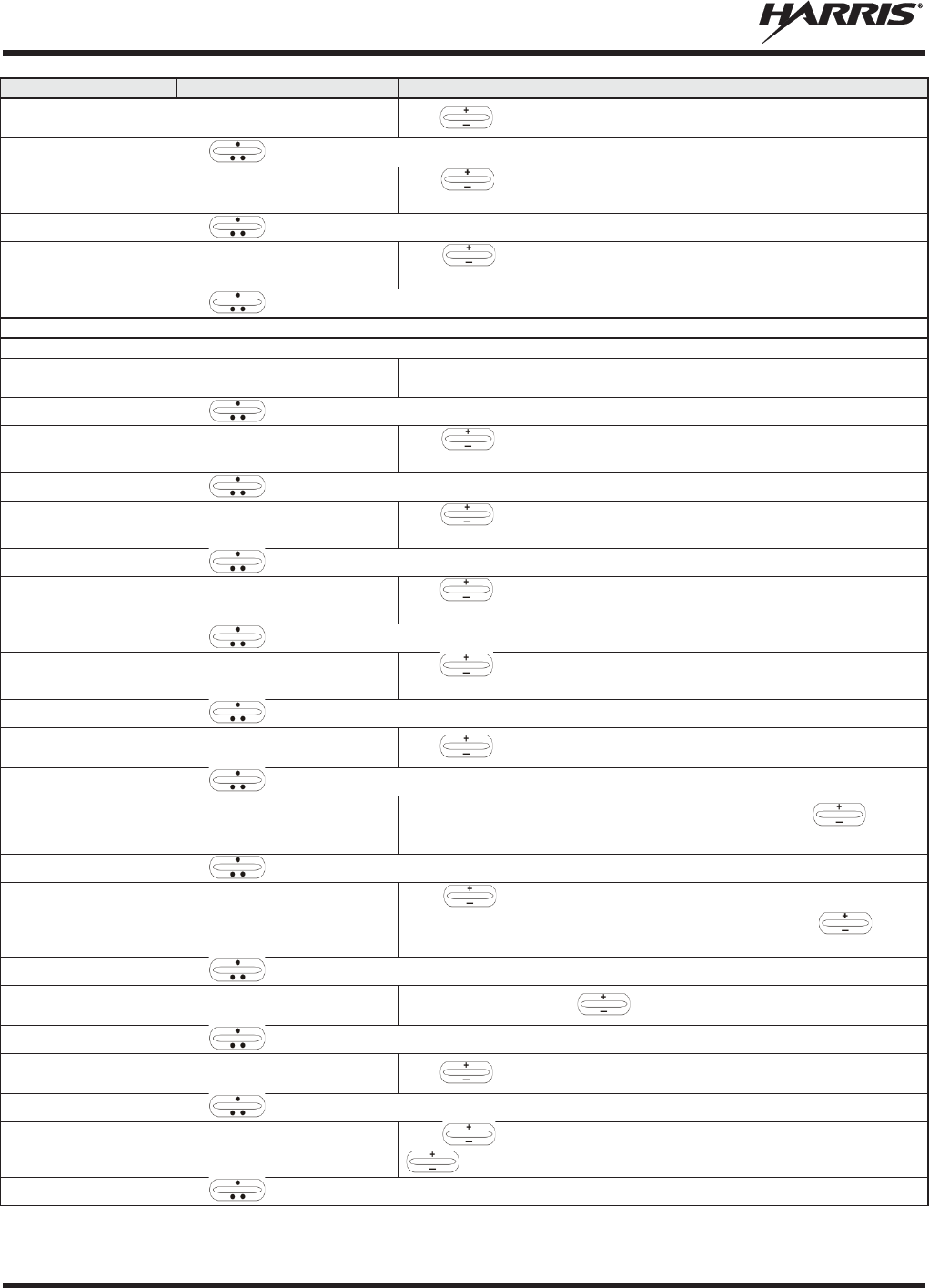
MM-014716-001, Rev. P
54
MENU NAME
RADIO DISPLAYS
USAGE NOTES
Display Brightness
“Bright Menu”
Use
to dim or brighten. Press MENU
to return to dwell display.
, CLR, or OPT
Side Tone Level
“Side Menu”
Use
to choose side tone level (Off, Low, Med, o
r High). Press
MENU to return to dwell display.
, CLR, or OPT
Intercom “INTERCOM”
Use
to turn intercom “On” or “Off.” Press MENU
to return to
dwell display.
, CLR, or OPT
See Next Page
See Previous Page
Selected Channel
“ChannelMenu”
Allows the user to display and change the current channel. Press
MENU to return to dwell display.
, CLR, or OPT
Scan Mode “ScnModeMenu”
Use
to select Scan Mode
(Normal, No Scan, or Fixed). Press
MENU to return to dwell display.
, CLR, or OPT
Talk group
Lock Out
“LockOutMenu”
Use
to choose a talk group for locking/unlocking. Press
MENU
to toggle “<” on (locked out) and off.
, CLR, or OPT
Priority 1
Talk group
“Priority1”
Use
to choose new priority talk group. Press MENU
to return to
dwell display.
, CLR, or OPT
Priority 2
Talk group
“Priority2”
Use
to choose new priority talk group. Press MENU
to return to
dwell display.
, CLR, or OPT
Emergency Dismiss
“EmgDismiss”
Use
to choose emergency talk group. Press MENU
to dismiss.
, CLR, or OPT
Alerts Received
“AlertsRcvd”
or oldest message
“No alerts” or alert message text scrolls in display. Use
to view
messages.
, CLR, or OPT
Alert Destination
“AlertDest”
Use
to choose a speed-dial number. Press MENU
to go to
“A
lertMsg” menu. Scroll through canned messages with .
Press
MENU to send message and return to dwell display.
, CLR, or OPT
Status LED “Status LED”
Press
MENU, then use
to turn the TX/RX LED “On” or “Off.”
, CLR, or OPT
Client Mode “Client Mode”
Use
to choose Client Mode (Network or SOI).
, CLR, or OPT
Speed Dial “SpeedDial”
Use
to choose a speed-dial number. Press MENU
, then use
to select canned message.
, CLR, or OPT
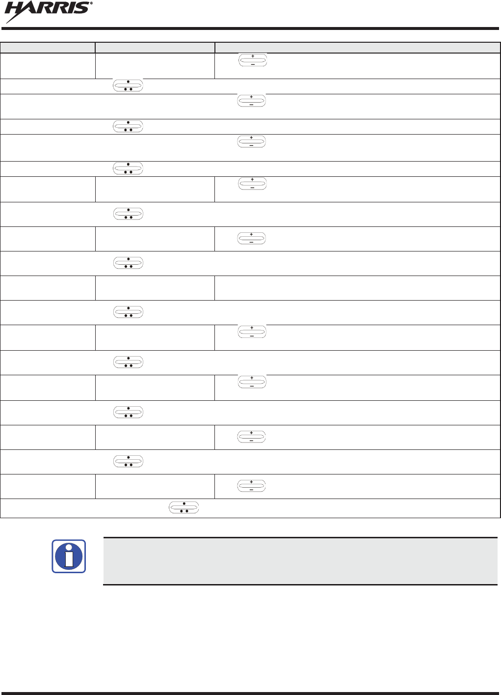
MM-014716-001, Rev. P
55
MENU NAME
RADIO DISPLAYS
USAGE NOTES
Profile Selection
“ProfileMenu”
Use
to choose an available profile. Press MENU
to return to
dwell display.
, CLR, or OPT
Request to Talk
Message
“RTT Msg”
Use
to scroll through available messages. Press MENU to
send the selected message.
, CLR, or OPT
Status Message
“Status Msg”
Use
to scroll through available messages. Press MENU
to send
the selected message.
, CLR, or OPT
Talk group Selection
“TalkGrpMenu”
Use
to choose a talk group in current profile. Press
MENU to
return to dwell display.
, CLR, or OPT
Site Lock “Site Lock”
Use
to scroll through sites. Press MENU to select site.
, CLR, or OPT
OTP Software Version
“Software Ver”
Displays OTP software version
Press MENU
to return to dwell display.
, CLR, or OPT
RF Diagnostics
“Diagnostics”
Use
to scroll through RF diagnostics displays. Press
MENU to
reset RF diagnostics counters.
, CLR, or OPT
Priority 3 Talk Group
“Priority 3”
Use
to choose Priority 3 talk group. Press MENU
to toggle “<”
on (selected) and off.
, CLR, or OPT
Public Address
“PA”
Use
to scroll to turn Public Address ON and OFF.
, CLR, or OPT
External Speaker
“SPKR SEL”
Use
to scroll to turn the External Speaker ON and OFF.
Use , CLR, or OPT to scroll through menus.
Menus vary depending upon system programming, radio hardware, and optional
configurations.
6.14 DUAL-TONE MULTI-FREQUENCY
Dual-Tone Multi-Frequency (DTMF) is the system used by touch-tone telephones. DTMF assigns a
specific tone frequency to each key so a microprocessor can easily identify its activation. The radio
supports DTMF with a system model control head (Figure 6-1). This allows for specific tasks such as
entering a user ID and password, or Selective Calling.
NOTE
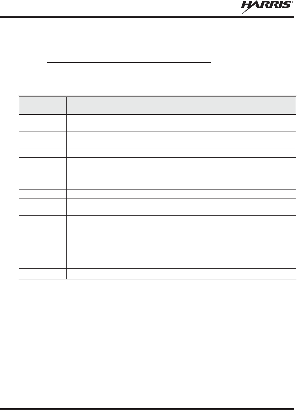
MM-014716-001, Rev. P
56
When a key on the DTMF keypad is pressed, the DTMF tone is played through the radio’s speaker.
6.15 KEYPAD
6.15.1 Keypad Commands (System Model Control Head)
To perform a command from the keypad, press the * key followed by one of the pre-set function keys as
follows:
Table 6-5: Keypad Function Commands
KEYPAD
COMMAND
FUNCTION
*0
Log off command:
*0## (logs the user off the system). See page 47
for additional
information.
*1
Login command:
*1<User ID> # <Password> #
(required for encryption). See page
46
for additional information.
*2
Status Message: *2 <0...9> #.
*4
Enter Scene of Incident Mode (SOI) on specified channel and band:
*4#<
ccc>#<bb># where ccc is the SOI channel number and bb
is the number assigned
to each frequency band.
Press *40# to exit SOI mode.
*5
RTT Message: *5 <0...9> #.
*7
Initiate Selective Alert command:
*7<Target ID>#[Choose Message]#
. See page 67
for additional information.
*8
Radio-to-Radio Call command:
*8<Selective call number># (PTT to dial).
*9
Public Switched Telephone Network (PSTN) Call command:
*9 <telephone
number
># (PTT to dial). See page 68 for additional information.
*32
Begin Manual Encryption command:
*32<Pre-Determined Encryption Key >#
1
– 16 digit encryption key for 128 bit encryption; 17 –
32 digit encryption key for 256
bit encryption. See page 72 for additional information.
*33
End Manual Encryption command
: *33#
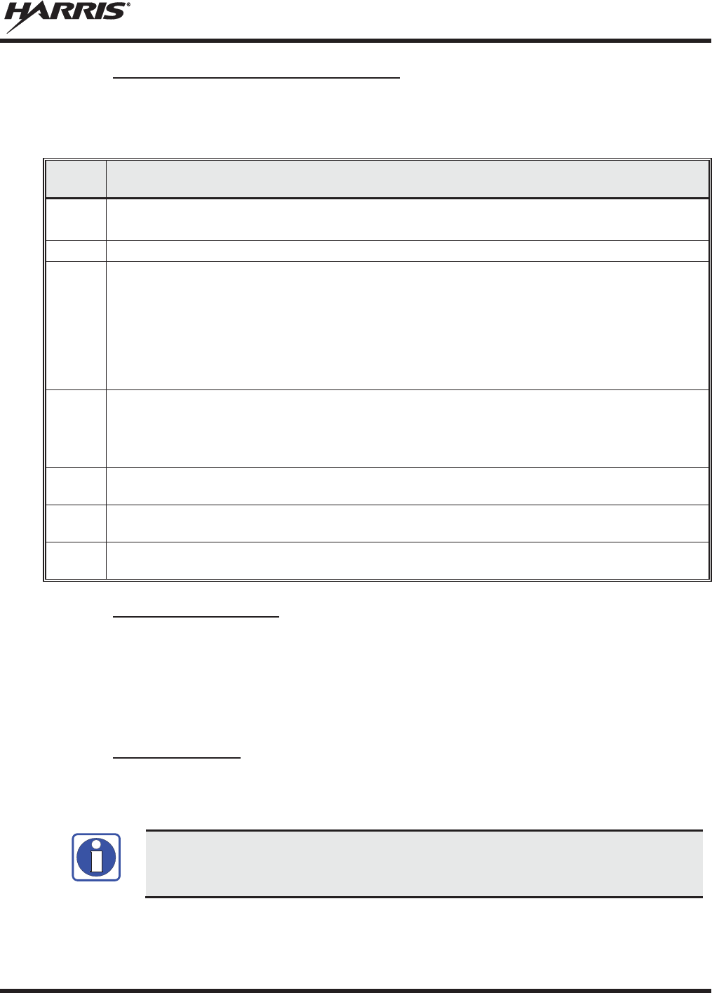
MM-014716-001, Rev. P
57
6.15.2 Quick Buttons (System Model Only)
Quick Keys are a two-button sequence that gives the radio user quick access to certain menu items. Quick
keys act as a toggle function.
Table 6-6: Quick Button Functions
QUICK
KEYS
FUNCTION
1#
Transition to ECP/XGP mode.
If ECP/XGP is not loaded in the radio, the radio displays “No App.”
2#
Stealth Mode On/Off.
3#
Scan Mode On/Off.
x
If the Scan Mode is Normal when the Scan Mode is toggled Off, the Scan Mode is
Normal
when toggled On again.
x
If the Scan Mode is Fixed when the Scan Mode is toggled Off, the Scan Mode is Fixed
when Scan Mode is toggled On again.
x
If the Scan Mode is Off when the radio boots up, the Scan Mode is Normal when Scan
Mode is toggled On.
4#
Lights/Tones On/Off.
This turns the TX/RX LEDs and Side
Tones On/Off.
If the radio is in Stealth mode, this quick button is disabled since the user is not able to turn on
the light/tones in Stealth Mode.
5#
This quick key sequence is used to set the current active profile to the default profile in the
personality as defined in the UAS.
7#
This quick key sequence is used to transmit the RTT Automatic Normal Message to the
console.
8#
This quick key sequence is used to transmit the RTT Automatic Priority Message to the
console.
6.15.3 Keypad Lock/Unlock
To lock or unlock the keypad:
1. Press the MENU button.
2. While the MENU button is pressed, within one second press the OPTION button.
3. A brief message is displayed on the 2nd line of the display (Kypd Lck, Kypd Unlck).
6.15.4 Password Entry
Password entry requires a system model control head. Password characters are encrypted on the display
using symbols to indicate the entry. The encryption symbols for each entry appears in the display as they
are scrolled through, for example: '-' and '+'. Press the # key twice to complete the entry process.
If the password is wrong, the radio does not successfully register with the network for
wide area voice reception. The radio can still be used in single
-site mode.
NOTE

MM-014716-001, Rev. P
58
6.15.5 DTMF Overdial
Using the keypad on a System Model, the radio can transmit DTMF tones corresponding to
numbers/characters 0 - 9, *, and # on the keypad. To overdial numbers/characters, transmit by pressing
and holding the PTT button and then, press the corresponding keys (one at a time) on the keypad.
6.16 CHANGE THE ACTIVE PROFILE
The radio can store up to sixteen (16) standard profiles, one of which is the currently active profile. To
change the currently active profile:
1. Scroll through the menu until “ProfileMenu” is displayed.
2. Use to scroll through the list of available profiles.
3. Profile becomes active when selected for longer than two (2) seconds, when the MENU is pressed, or
when the menu is changed.
6.17 ENABLE/DISABLE VOLUME SIDE TONE
The Volume Side Tone sounds when adjusting the volume control.
To enable or disable this tone:
1. Power off the radio.
2. Press and hold the B button while turning the radio on.
6.18 CHECK OR CHANGE THE SELECTED TALK GROUP
Each profile stored in the radio can have up to sixteen (16) talk groups. One talk group within the
currently active profile is set as the “selected talk group.” For the radio user, the selected talk group is
typically the focus of most voice transmissions and receptions. There are two ways to change the selected
talk group:
First Method:
1. Scroll through the menu until “TalkGrpMenu” appears on the bottom line of the display. The
currently selected talk group appears in the top line of the display.
2. Use to scroll through the available list of talk groups in the active profile. This list is
determined by the OpenSky network administrator.
Second Method:
From the dwell display, use the talk group selection knob or to scroll through the available list of
talk groups in the active profile.
6.19 ADJUST DISPLAY AND BUTTON BACKLIGHT BRIGHTNESS
1. Scroll through the menu until “Bright Menu” appears.
2. Use to increase or decrease brightness. Display and button backlight brightness immediately
dims or brightens.
Or
If enabled via programming, increases/decreases brightness.

MM-014716-001, Rev. P
59
6.20 STEALTH MODE
For some users, it is important to be able to turn off the radio’s display lights, button backlighting, volume
and side tones, but not radio traffic. For example, in covert operations, lights and sounds could
inadvertently expose an otherwise unobservable radio user. For this purpose, the radio has a Stealth
feature that disables the radio display light, indicator light, and audible side tones.
When Stealth Mode is on, the radio continues to scan the programmed list of talk groups and the user can
key-up on the selected talk group. All buttons are disabled except for PTT, Emergency, 2# and MENU.
Since the screen is blank the user cannot see the result of other button presses.
6.20.1 Enable Stealth Mode
1. Scroll through the menu until “StealthMenu” appears.
2. To immediately turn Stealth Mode on, press (+) or (-) with .
Or
Press quick button command 2# on the System Model control head.
6.20.2 Disable Stealth Mode
To turn Stealth Mode off, press quick button command 2# or the MENU button on the radio’s front panel.
6.21 ADJUST SIDE TONE AUDIO LEVEL
The radio sounds confirming tones called “side tones” when its buttons are pressed. Most users find this
audible confirmation helpful when navigating the menus. Side tone audio level can be adjusted or turned
completely off using the “Side Menu.”
For covert operations, it may be necessary to turn off side tones. For safety’s sake, turning off the radio
during covert operations is not recommended.
To temporarily disable the side tones that could expose the user’s presence and position, use the menu
buttons to access the “Side Menu” and select “Off” from the menu choices.
If the radio is operating properly but side tones are not heard when the menu buttons are pressed, the side
tones are probably turned off. To turn them back on, access the “Side Tone” menu and select a setting
other than “off.”
Use the following procedure to set side tone level:
1. Scroll through the menu until the “Side Menu” appears in the bottom line of the display.
2. Use to change to the desired level (Off, Low, Medium, and High). To turn side tones
completely off, use the “Off” setting.
MM-014716-001, Rev. P
60
6.22 CHANGE OPERATING MODE
1. Scroll through the menu until “App Mode” appears in the bottom line of the display.
2. Use to choose an available mode. Press MENU and confirm (Y/N) with and press
MENU again.
Or
Preset button C can be configured via programming to reboot the radio into a particular application mode.
Or
Quick Button command 1# transitions the radio to ECP/XGP mode. If ECP/XGP mode is not loaded in
the radio, the radio displays “No App.”
6.23 RECEIVE AND TRANSMIT VOICE CALLS
As soon as the radio completes the startup/login/provision/self-test sequence and registers on the
OpenSky network, voice calls from talk groups in the active profile are audible.
6.23.1 Receive a Voice Call
The
Alias/User ID/Talk Group
name are only displayed if that dwell display option is
select
ed using the MENU button. For example, if the user sets
the dwell display option
to profile, the profile continue
s to be displayed when a call is received.
No action is required to receive a voice call. The display responds to incoming voice calls as follows:
x When the dwell display is set to received talk group, the scan mode is Normal or Fixed:
a. If the received talk group matches the selected talk group, then the alias (if available) or user ID
of the incoming caller is displayed.
b. If the received talk group does not match the selected talk group, then the received talk group
name is displayed
x When the dwell display is set to received talk group and the Scan Mode is None, the radio only
receives voice on its selected talk group. When the call is received, the alias (if available) or the user
ID of the incoming caller is displayed.
x When the dwell display is not set to received talk group, then there is no display indication of an
incoming call.
A radio receiving a System All Call displays “All Call” instead
of the alias.
A radio
not transmitting on a
talk group in emergency status drops
all other calls to scan into
an
All Call.
Refer to Section 6.27 for detailed information on talk group scanning. Refer to Section 6.32 for detailed
information regarding sending and receiving encrypted calls.
NOTE
NOTE

MM-014716-001, Rev. P
61
6.23.2 Transmit a Voice Call
Transmit a voice call as follows:
1. Turn the radio on.
2. If required, login to the network using a user ID and password (see Section 6.4).
3. Select the talk group on which you want to transmit.
4. Press and hold the Push-to-Talk (PTT) button on the hand-held microphone, pause for a moment,
and then speak normally. For maximum clarity, hold the microphone approximately 2 inches from the
mouth and do not shout or whisper into it. If the call is queued by the network, wait for the grant tone
to sound before speaking.
5. Release the PTT button when finished speaking.
Refer to Section 6.32 for detailed information regarding sending and receiving encrypted calls.
6.24 ADJUST AUDIO TREBLE LEVEL
The tone of received signals can be adjusted using the radio’s “Treble Menu” as follows:
1. Scroll through the menu until “Treble Menu” appears. The radio’s current treble level setting
indicates in the top line of the display. There are four levels available: low, medium, medium-high,
and high.
2. Use to increase or decrease treble level.
3. Press the MENU button or wait a few seconds to return to the Dwell Display.
6.25 INTERCOM MODE
The optional intercom mode gives users at multiple control heads connected to the same radio the ability
to communicate with each other without transmitting over-the-air. Turn intercom mode on and off using
the “INTERCOM” menu as follows:
1. Scroll through the available menu items until “INTERCOM” appears in the display.
2. Use to toggle between “On” and “Off.”
When intercom mode is turned on:
x Incoming voice calls override intercom communications for the duration of the voice call. The radio
and associated control heads remain in intercom mode and intercom communications resume when
the voice call ends.
x “TG: INTERCOM” appears in the control head’s display when talking on the intercom. This indicates
microphone audio is not sent out on the selected talk group; rather, it remains localized between the
radio control positions (i.e., the control heads connected to the mobile radio).
x If a call exists on the currently selected talk group when a PTT button is pressed at one of the control
heads, “TG: in use” appears in the display to indicate intercom mic audio cannot preempt the call on
the talk group.
MM-014716-001, Rev. P
62
A user at a radio with only one control head/front panel can turn intercom mode on. In
this case, pressing the microphone’s PTT button does
NOT send micr
ophone audio
anywhere.
6.26 TALK GROUP LOCK OUT
There are two ways of focusing voice communications by suppressing calls from talk groups in the
currently active profile:
1. No Scan: By turning scan off (selecting “No Scan” via the “ScnModeMenu”), only the selected talk
group is audible.
2. Lock Out: By locking out selected talk groups, the “chatter” of the locked out talk groups cannot be
heard. This focuses the user’s scanning resources to calls only on desired talk groups.
Talk group lock out is a scan-related feature. With lock out, one or more talk groups in the active profile
can be temporarily disabled from being scanned. Calls are not received on locked-out talk groups. Lock
out settings are not retained between profile changes or when the radio is power cycled.
Lock out is a listening (receive) function and only blocks received calls on locked out
talk groups. Lock out does not affect transmit capability. The above methods do not
apply to recent emergency lock outs.
Only talk groups in the active profile can be locked out, since they are the only talk groups whose voice
calls can be heard on the radio.
P1
, P2, and P3 talk groups cannot be locked out.
The default emergency and emergency-capable talk groups can be locked out if they are NOT in an
emergency state. If a talk group is locked out and is subsequently changed to the currently selected talk
group, it is automatically unlocked by the radio so the user can hear calls on the talk group. The radio may
be configured so all talk groups are automatically locked out by default. In this case, they must be
manually unlocked, if desired.
6.26.1 Lock Out a Talk Group
1. Scroll through the menu until “LockOutMenu” appears in the bottom line of the display. The name of
a talk group in the currently active profile appears in the top line.
2. Use to scroll through the list of talk groups, if any, until the desired talk group for lock out
appears in the top line of the display.
3. Press the MENU button to lockout the displayed talk group. A less than symbol (<) appears next to
the talk group’s name.
4. Repeat steps 2 and 3, as needed, to lock out additional talk groups.
The dwell display re-appears a few seconds after button presses end.
While scrolling through talk groups in the active profile, the only talk groups that appear in the
“LockOutMenu” are those in the active profile.
CAUTION
NOTE
NOTE
MM-014716-001, Rev. P
63
6.26.2 Unlock a Talk Group
1. Scroll through the menu until “LockOutMenu” appears in the bottom line of the display. The name of
a talk group in the currently active profile appears in the top line.
2. Use to scroll through the list of talk groups, if any, until the talk group desired for unlocking
appears in the top line of the display. A less-than symbol (“<”) appears next to the name of a talk
group that is currently locked out.
3. Press the MENU button to unlock the talk group. The less-than symbol (“<”) next to the name of the
talk group disappears. The dwell display appears as soon as the radio acknowledges the selection.
x
Changing the active profile removes any lock outs you have made.
x
Turning off the radio removes any lock outs you have made.
6.27 SCANNING
Three scanning modes are available for the radio, but only one can be active at any time. Changing the
scanning mode changes the way the radio scans voice calls for all of profiles in the radio personality, no
matter which profile is or becomes active.
As described in Table 6-7, the choice of scanning mode changes the span of communications with all the
talk groups in the radio’s profiles, but does not affect interaction with the talk groups.
Table 6-7: Scan Modes
SCAN MODE
EXPLANATION
No Scan
Eliminates distractions.
Full communications (transmit and receive) on selected talk group.
No calls received from other talk groups.
Normal
(Default)
The user can scan all talk groups in the active profile that are not locked out as long as there is
demand on the site.
Priority (P1
, P2, and P3) groups are user selectable.
Receive calls from more than one talk group, if available from the current site.
Allo
ws dragging of the selected talk group, P1, P2, P3,
and default emergency talk groups to the
site on which the radio is registered. (If other calls are available at the site, they also can be heard
but they are not be actively dragged.)
The default emergen
cy talk group, as well as any emergency-
enabled talk groups, is only dragged
if it is in emergency mode.
Fixed
Functions the same as Normal Scan Mode, except the priority groups are fixed to the selected
profile’s pre
-defined P1 and P2 groups (configured via the UAS).
NOTE

MM-014716-001, Rev. P
64
6.27.1 Check or Change Active Scan Mode
The currently active scan mode does not appear in the dwell display. To check it, access “ScnModeMenu”
and observe it in the top line of the display. To change the active scan mode:
1. Scroll through the menu until “ScnModeMenu” appears in the display.
2. Use to scroll through the scan options until the desired mode appears. See Table 6-7.
Or
Use the quick button option 3#.
6.27.2 Scan Priority
The following lists the scanning priority order (from highest to lowest):
x System All Call
x Selected talk group in emergency state
x Default emergency group in emergency state
x Selected talk group
x Emergency capable group in emergency state
x Priority 1 talk group
x Priority 2 talk group
x Priority 3 talk group
x Other (non-priority)
6.27.3 Change Priority 1 and Priority 2 Talk Groups
Follow this procedure to set talk groups in the current profile as the Priority 1 or Priority 2 talk group:
1. Scroll through the menu until “Priority1” or “Priority2” appears in the bottom line of the display
(Priority 1 group has higher priority than the Priority 2 group. The talk group currently set as the
priority talk group appears in the top line of the display.
2. Use to select a new priority talk group.
3. Press the MENU button to set the newly selected talk group as the priority talk group.
6.27.4 Change Priority 3 Talk Groups
Follow this procedure to set talk groups in the current profile as Priority 3 talk groups:
1. Scroll through the menu until “Priority 3” appears in the bottom line of the display. The name of a
talk group in the currently active profile appears in the top line.
2. Use to scroll through the list of talk groups, if any, until the desired talk group for Priority 3
appears in the top line of the display.
3. Press the MENU button to select/deselect the displayed talk group as a Priority 3 talk group. A less
than symbol (<) appears next to the talk group’s name.
4. Repeat steps 2 and 3, as needed, to select/deselect additional talk groups.
MM-014716-001, Rev. P
65
6.28 MAKE SELECTIVE CALLS
Selective Calling is a feature that allows two radio units to obtain and utilize an independent voice path
for a private call. Radios can be configured to both initiate and receive Selective Calls or to only receive
Selective Calls.
In the OpenSky system, a source radio can be configured to initiate Selective Calls through a pre-
programmed list in memory. This method uses the “speed dial list” set up by the OpenSky network
administrator and provisioned as part of the registration process.
In addition, a properly equipped source radio can initiate a Selective Call to any radio in the system by
entering the ten-digit voice user ID (which looks like a telephone number) of the target device. Entering a
Selective Call number without using the speed dial feature requires a system model control head (Figure
6-1). See Section 6.14 for more detail.
Selective Call
s are terminated if an emergency is declared. The network limits
Selective
Call
s to ten (10) minutes maximum.
Table 6-8 lists and defines the messages that may be displayed by the radio during a Selective Call.
Table 6-8: Status of Selective Call
STATUS MESSAGE
DEFINITION
Busy
Peer is involved in another selective/PSTN call.
D
isconnect
Selective/PSTN call was terminated for unknown
reason.
Network Err
Selective/PSTN call cannot continue because of
an unspecified network error.
Reject
Peer or this user declined request to establish
selective/PSTN call.
Unavailable
Peer cannot be reached for selective/PSTN call.
Calling
Calling peer (i.e., for selective or PSTN calls).
Connecting
Establishing selective/PSTN call with peer.
Hangup
Peer or this user terminated selective/PSTN call.
Lim 10 min
Selective/PSTN call limited to 10 minutes.
Timing Out
Selective/PSTN call has 10 seconds remaining
before limit is reached (shown for 5 seconds).
Sel Call
Selective Call is active.
6.28.1 Manually Dial a Selective Call (System Model Control Head)
1. Press *8 on the keypad.
2. Enter the number of the radio to be called (e.g., 027-001-0006). If the region number (first 3 digits;
027 in this example) is the same as this radio’s region number, these digits do not need to be entered.
Likewise, if the region and agency numbers (first 6 digits; 027-001 in this example) are the same as
this radio’s numbers, these digits do not need to be entered. Leading zeros can also be ignored.
3. Press and release the # key.
4. Wait approximately two (2) seconds.
NOTE
MM-014716-001, Rev. P
66
5. Press and release the PTT button to initiate the Selective Call request. When the called party accepts
the call, press the PTT again and begin speaking.
6.28.2 Speed Dial a Selective Call
Speed dial numbers are defined and provisioned by the OpenSky network administrator
and cannot be manually entered into the radio by the user. Contact the administrator if
changes to the speed dial list are required.
1. Scroll through the menu until “SpeedDial” appears in the bottom line of the display.
2. Using , scroll through the pre-programmed speed-dial numbers until the desired number
appears in the display.
3. Press and release the PTT button to ring the other user.
a. The ring tone is sounded.
b. If the other user accepts the call, the called user’s alias appears in the initiating caller’s display.
The two are now in a private call until one ends the call, the call is terminated due to an initiated
emergency, or the maximum time limit of ten (10) minutes is reached.
4. To end the call, press the # button or (-) using .
6.28.3 Receive a Selective Call
When someone calls in from another radio using the Selective Call function, a ring sounds in the speaker
and/or headset. Press up or down using or any number key to accept an incoming Selective Call.
Press the microphone’s PTT button when speaking (transmitting) to the caller.
Press the # button or (-) using to reject an incoming Selective Call.
A Selective Call is interrupted if an emergency is declared on a monitored talk group.
6.28.4 Terminate a Selective Call
Press the # button or (-) using to terminate an incoming Selective Call.
6.29 SELECTIVE ALERT
Selective alert messaging is an OTP feature allowing one of up to eight (8) pre-programmed text
messages (refer to Section 6.29.3) to be sent from one radio to another. The user specifies a destination
radio’s User ID, selects one of the pre-programmed text messages, and then transmits it to the destination
radio. The message delivery system adds time-of-day information and forwards the message to the
destination (receiving) radio. The sending radio receives a brief message noting the status of the
transmission. Refer to Table 6-9 for a list of possible status messages.
The first few characters of a message are part of the message text entered when the message is
programmed. This programming is performed by the system or network administration personnel.
Messages successfully received by the destination radio are stored until deleted or until the radio is power
cycled.
NOTE

MM-014716-001, Rev. P
67
6.29.1 Send Selective Alert Messages
The destination radio’s User ID can be selected via the menu or via the keypad on the system model
control head.
Menu Button Method:
1. Scroll through the menu until “AlertDest” (Alert Destination) appears in the bottom line of the
display. The current speed dial number scrolls on the top line.
2. Use to change to a different speed-dial number.
3. When the desired speed-dial number appears, press the MENU button to activate the selection.
4. Choose and send the message.
Keypad Method (System Model Control Head):
To select the destination radio’s User ID using the keypad, perform the following:
1. Press *7 on the keypad. “AlertDest” appears in the display.
2. Enter the number of the destination radio (e.g., 027-001-0006) using the DTMF keypad. If the region
number (first 3 digits; 027 in this example) is the same as this radio’s region number, these digits do
not need to be entered. Likewise, if the region and agency numbers (first 6 digits; 027-001 in this
example) are the same as this radio’s numbers, these digits do not need to be entered. Leading zeros
can also be ignored. Refer to Section 6.14.
3. Press the # key to enter the number.
Choose and Send the Message
After specifying the destination radio’s User ID (Section 6.29.1), the radio automatically allows you to
choose a message. The current message scrolls across the top line of the display. To choose a message:
1. Scroll through the message list using . The next available message in the list is displayed.
Pause between each arrow button press to observe the entire message as it scrolls across the top line
of the display.
2. To select and send the displayed message, press the MENU button, or press the # button on the
keypad.
3. The status of the sent message is momentarily displayed (Table 6-9).
Table 6-9: Status of Selective Alert
STATUS MESSAGE
DEFINITION
Alert Sent
Alert message successfully sent to target.
Delivered
Alert message passed to network.
Delivering
Delivering alert message to target.
New alert
New alert message received.
No alerts
No alerts are available.
Busy
VNIC congested and cannot deliver message at
the current time.
Dest Down
Destination home VNIC down.
Ignored
Destination is either non-responsive or does not
care to respond.
Inv Option
Distribution option is invalid.

MM-014716-001, Rev. P
68
STATUS MESSAGE
DEFINITION
Not Reg
Destination is not registered.
Partial
Not all destination ESN instances reachable.
Unauth Alrt
Unauthorized service function; initiator is not
authorized to send the selected service message.
Unknown Msg
Unknown status received from VNIC.
Unreachable
Alert destination cannot be reached.
6.29.2 Receive Messages
When a selective alert message is received by a radio, a four-beep tone (one low, two high, and one low)
is heard and “New alert” flashes until the new message is read. Up to eight (8) received messages are
stored. If another message is received, the first (oldest) message is automatically deleted to make room for
new incoming messages.
Display Received Messages
1. Scroll through the menu until “AlertsRecvd” (Alerts Received) appears in the bottom line of the
display. “No alerts” or the last received (newest) message appears in the display. It is preceded by the
time the message was received, and the sender’s name/alias.
2. View other received messages using .
3. To delete the message currently being viewed, press the MENU button.
Delete Received Messages
To delete a received message:
1. Display the message.
2. Delete the message by pressing the MENU button.
3. Confirm the deletion by pressing the MENU button again.
6.29.3 Define Pre-Programmed Messages
All selective alert messages are pre-defined by the radio system’s maintenance personnel. These messages
are sometimes referred to as “canned” messages. Custom selective alert messages cannot be created by
the radio user. The entire selective alert message can include up to 99 text characters.
6.30 TELEPHONE INTERCONNECT CALLS (SYSTEM MODEL CONTROL
HEAD)
6.30.1 Place an Interconnect Call
If the radio system is equipped with Public Switched Telephone Network (PSTN) interconnect
equipment, telephone calls can be made from the XG-75M/M7300 using this procedure:
1. Press the * 9 keys.
2. Enter the telephone number. Ignore dashes/spaces, and precede the number with any required access
digits such as a 1 for long distance.
3. Press the # key.

MM-014716-001, Rev. P
69
4. Wait a few seconds and then press and release the mic’s PTT button to initiate the call. An initial ring
tone plays indicating call initiation. Once the gateway picks up the call, another ring tone sounds.
5. When the caller answers, press the PTT button when speaking and release it to listen to the caller.
6. To hang-up, press the # button or (-) using .
6.30.2 Receive an Interconnect Call
When receiving an Interconnect Call, a ring sounds in the speaker and/or headset. Press up or down using
or any number key to accept an incoming Interconnect Call. Press the microphone’s PTT button
when speaking (transmitting) to the caller.
Press the # button or (-) using to reject an incoming Interconnect Call.
6.31 EMERGENCY COMMUNICATIONS
The XG-75M/M7300 mobile radio can transmit both emergency voice calls and emergency alerts over the
entire network. OpenSky handles emergency calls and alerts with the highest priority.
For critical voice communications, an emergency call can be raised on the default talk group or the
currently selected talk group by “declaring” an emergency on the talk group. The exact talk group is
determined by the currently active profile. After successfully declaring an emergency on a talk group, the
declaring radio’s microphone remains “hot” for a predetermined amount of time. In other words, the radio
transmits audio for a period of time even when the microphone’s PTT button is not pressed. An
emergency talk group is provided greater priority and infinite hang-time by the radio system’s
infrastructure. Hang-time is the maximum duration of quiet time between transmissions on the talk group
before the infrastructure assets are automatically taken away. Because an emergency call is handled on a
talk group, it is received by all radios and consoles monitoring the talk group.
An emergency alert is a data message sent by the radio to the MIS console (or any console capable of
receiving it). It identifies the radio declaring the emergency, and the radio’s location (if the radio is
equipped with a GPS receiver). Voice audio is not automatically transmitted during the emergency if the
administrator configures the radio for alert notification only.
6.31.1 Declare an Emergency Call or Alert
1. Press the red emergency button on the radio to enter emergency mode. The emergency is raised after
the emergency raise delay [default is one (1) second].
x If the active profile of the unit initiating the emergency is configured for Emergency Alert, the
emergency alert signal is sent to registered alert servers, such as the dispatcher console.
x If the active profile of the unit initiating the emergency is configured for Emergency Call, the
talkgroup is placed into emergency status notifying other radios and the emergency alert signal is
sent to the dispatcher console.
x If the emergency behavior of the active profile is Current, the active, selected voice group
becomes the default emergency voice group.
x If the emergency behavior of the active profile is Default, the radio moves to the default
emergency voice group of the profile and this talk group becomes the select talk group.
2. The display alternates between “Emergency” and whatever option is selected for the 2nd line of the
dwell display.
MM-014716-001, Rev. P
70
If the attempt is unsuccessful, “E-PEND” flashes periodically and a retry is queued for 10 seconds. If
unsuccessful because of lost sync, retry occurs immediately upon reacquiring sync. On each retry attempt,
radio temporarily displays “E-RETRY.” This process repeats until the emergency is successfully
declared.
6.31.2 Silent Emergency
When this feature is enabled and an emergency call or alert is declared by pressing the emergency button,
the radio does not play a tone and displays an abbreviated emergency message (default is EBA). This
feature is enabled or disabled via programming or via the menu.
If the Silent Emergency feature is enabled or disabled via programming, the setting
survive
s power cycle. Enable/Disable selection via the menu does
NOT survive power
cycle and the enable/disable
state reverts to the programmed setting at power up.
6.31.3 Clear an Emergency Call or Alert
Check with the system administrator to ensure that the radio is programmed to allow an
emergency to be cleared.
If enabled via programming, clear an emergency by:
1. Pressing and holding the CLR/CLEAR button and simultaneously pressing the emergency button.
2. After the Emergency Cleared Tone sounds, release both buttons.
If the radio is in
Stealth Mode, clearing the emergency takes the radio out of
Stealth Mode.
6.31.4 Receive an Emergency Call
Upon receiving an emergency call declared by another radio:
x An emergency tone sounds in the radio’s speaker/headset (three short high-pitched beeps).
x “EMERGENCY” flashes in the display if the radio is not in stealth mode. When receiving voice in an
active emergency, the flashing “EMERGENCY” is inhibited so that the alias of the sender can be
seen.
x On receiving radios with the emergency talk group selected, the alias of the sending party is displayed
for 5 seconds during the open-mic period, then the word “Emergency” flashes on the second line of
the display and continues until the emergency state ends.
x If scan mode is set to “No Scan” and the emergency was declared on the selected talk group, audio on
the emergency talk group is heard in the speaker/headset. See page 63 for additional information on
“No Scan” operation.
x If scan mode is set to “No Scan” and the emergency was declared on a talk group other than the
selected talk group, the emergency talk group (identified by an “*”) must be selected before audio on
it is heard in the speaker/headset.
NOTE
NOTE
NOTE
MM-014716-001, Rev. P
71
x If scan mode is set to “Normal” and the emergency was declared on the selected talk group, the
selected/emergency talk group’s name remains in the top line of the display. Audio on the emergency
talk group is heard in the speaker/headset.
x If scan mode is set to “Normal” and the emergency was declared on a talk group other than the
selected talk group, the emergency talk group’s name appears in the bottom line of the display. Audio
on the emergency talk group is heard in the speaker/headset.
x The declaring radio's alias appears in the bottom line of the display when the emergency talk group is
selected.
x An emergency call can be dismissed as described in the following section.
A radio declaring an emergency on a talk group has a “hot” mic time period of typically
ten (10) seconds just after it declares the emergency. This time period may be adjusted
by system or network administration personnel on a per radio basis.
6.31.5 Dismiss an Emergency Call
An emergency is dismissed for a configurable amount of time only (default = 5 minutes).
To ignore an emergency call declared by another radio user:
1. Scroll through the menu until “EmgDismiss” appears in the display.
2. Press until the talk group in the emergency state appears, as indicated by an asterisk (*)
following the talk group’s name.
3. Press the MENU button.
The emergency dismiss timer is cleared when the emergency is cleared.
6.32 ENCRYPTION
In the OpenSky network, both data and voice use a 128-bit or 256-bit key encryption standard published
by the Federal Information Processing Service (FIPS), called Advanced Encryption Standard (AES). AES
is approved by the U.S. Department of Commerce for encryption of classified materials.
When encryption is enabled on the network, data is encrypted from the MDIS to the Mobile End System
(MES) (e.g., XG-75M/M7300 mobile radio). This form of encryption provides air-link security.
Voice encryption is handled either automatically or manually. Automatic encryption is initiated through
the Unified Administration Server (UAS) for a specific talk group and requires nothing from the user.
Manual encryption is initiated by two or more radio users and requires system model control heads. Both
methods of encryption are discussed in the following sections.
6.32.1 Automatic Encryption
For automatic encryption, a network administrator selects the talk group to be encrypted at the interface to
the UAS. Once the talk groups have been selected and identified as secure, credentials for key generation
NOTE
NOTE
NOTE
MM-014716-001, Rev. P
72
are generated automatically by the system and provisioned to authorized users. This process requires that
authorized users login to the network and be authenticated. Encryption keys require no manual handling
and are never sent “in the clear” over any network interface or air-link.
1. “Pls Login” appears displayed in the bottom line of the dwell display.
2. Login normally using the keypad on a system model control head to enter User ID and Password.
If a user is engaged in a call on a talk group encrypted at the network administrator level, “Secure Call”
appears in the bottom line of the dwell display if the user is logged in to that talk group.
If a secure call is in progress elsewhere and the user has not logged in, the bottom of the dwell display
alternates between “No Access” and the alias of the radio that is currently engaged in the secure call.
The radio
can also be programmed to automatically login and enable encryption.
6.32.2 Manual Encryption (System Model)
Two or more users can manually encrypt a call, if enabled, without an established encrypted talk group. A
pre-determined key is required at each radio.
The key must be pre
-
determined by the users prior to making a manually encrypted call
on a talk group and is entered into the radio using the keypad. For 128 bit encryption, this
key is between 1 and 16 digits. For 256 bit encryption, this key is between 17 and 32
digits.
If two communicating radios have different (manually
-
defined) keys, receive audio at
each radio sounds garb
led.
With manual encryption enabled, unencrypted radio users on the talk group can still make standard voice
(unencrypted) calls on the talk group. However, if an unencrypted user attempts to transmit on the talk
group when one of the encrypted users is already transmitting on the talk group, the unencrypted radio
sounds a deny tone and “No Access” appears in the display. Also, the encrypted user can hear standard
unencrypted calls, but cannot respond while still manually encrypted.
Do
not set a talk gro
up for manual encryption if it has been set for encryption by the
network administration personnel.
Perform the following to transmit or receive manually encrypted calls:
1. Press *32 on the keypad.
2. Enter the key (1 – 16 digits for 128 bit encryption; 17 – 32 digits for 256 bit encryption).
3. Press the # key.
4. To end manual encryption, press *33#.
If a user is engaged in a call on a talk group that has been manually encrypted at the radio level, the user
sees “Secure Call” on the bottom of the dwell display.
NOTE
NOTE
CAUTION
MM-014716-001, Rev. P
73
If a secure (encrypted) call is in progress, and the user has not entered the key, the bottom of the dwell
display alternates between “No Access” and the alias of the radio that is currently engaged in the secure
call.
Once the user has terminated manual encryption, “UnSecure” appears temporarily in the bottom line of
the dwell display.
6.33 PRESET BUTTONS
The front panel contains three buttons labeled A, B, and C. By holding one of these buttons down for
approximately three (3) seconds, the following current information is saved to the function of that button:
x Currently selected Priority 1, Priority 2, and Priority 3 talk groups
x Currently selected profile
x Currently selected talk group
x Lock outs
x Scan state
x Intercom mode
After changing systems, groups, scan state, etc., simply press the preset button to restore the settings.
Presets are saved and restored to/from non-volatile memory. Changing the User ID (login in as a different
user) clears the presets since they are stored on a per-user basis. Changing control heads does not recall
presets for the previous control head.
Preset button C can be configured via programming to reboot the radio into a particular
application mode, toggle the external speaker OFF/ON, toggle the Public Address
OFF/ONN or toggles the Selective Call Alert. Contact your system administrator to
determine if this feature is enabled in your radio.
6.34 STATUS MESSAGES
If enabled via programming, the radio can transmit a pre-programmed status message. Section 8.30.1
describes how to send a status message via the keypad and Section 8.30.2 describes how to send a status
message via the menu.
6.34.1 Send Status Message via the Keypad (System Model Only)
1. Press *2 <0…9> # on the keypad.
2. A Status message can be associated with each key (0 – 9). This text is displayed on the first line of the
display when the key is pressed until another key is pressed.
x If no messages have been configured, “No Messages” is displayed.
x If a message is not assigned to a key, “No Entry” is displayed for the keypad sequence.
x You can press multiple keys to select the desired Status message.
3. The # key terminates the keypad sequence and sends the currently selected status message. If no
messages have been configured or no message is associated with the key, no message is sent and an
error tone is played.
Press * to cancel the keypad sequence.
NOTE

MM-014716-001, Rev. P
74
6.34.2 Send Status Message via the Menu
1. Scroll through the menu until “Status Msg” appears and press MENU. If no messages have been
configured, “No Messages” is displayed.
2. Scroll through the available messages using . The configured Status message is displayed on
the 1st line of the display.
3. Press the MENU button to send the currently selected message. If no messages have been configured,
no message is sent and an error tone sounds.
Press up or down with to cancel status message selection.
6.35 REQUEST TO TALK (RTT) MESSAGES
If enabled via programming, the RTT message feature allows you to send either a short service message
to the VNIC. Section 6.35.1 describes how to send an RTT message via the keypad and Section 6.35.2
describes how to send an RTT message via the menu. Note that only one RTT message can be
programmed into the radio.
6.35.1 Send RTT Message via the Keypad (System Model Radios Only)
1. Press *5 <0…9> # on the keypad. The key associated with the RTT message (0-9) is configured via
programming.
2. This message is displayed on the first line of the display when the key is pressed until another key is
pressed.
x If no message has been configured, “No Message” is displayed.
x If a message is not assigned to the key, “No Entry” is displayed for the keypad sequence.
3. The # key terminates the keypad sequence and sends the currently selected RTT message. If no
message has been configured or no message is associated with the key, no message is sent and an
error tone is played.
Press * to cancel the keypad sequence.
6.35.2 Send RTT Message via the Menu
1. Scroll through the menu until “RTT Msg” appears and press MENU. If no message has been
configured, “No Messages” is displayed.
2. Use to select message. The configured RTT message is displayed on the 1st line of the display.
3. Press the MENU button to send the currently selected message. If no message has been configured,
no message is sent and an error tone sounds.
Press to cancel RTT message selection.
6.35.3 Send RTT Automatic Normal Message via the Quick Button
Press 7# buttons to send RTT Automatic Normal Message to the console.
6.35.4 Send RTT Automatic Priority Message via the Quick Button
Press 7# buttons to send RTT Automatic Priority Message to the console.
MM-014716-001, Rev. P
75
6.36 GPS COORDINATES
The radio’s current latitude and longitude coordinates may be displayed using the “GPS” menu. The
following procedure assumes a GPS antenna is connected to the radio and it is receiving adequate signals
from GPS satellites:
1. Scroll through the menu until the “GPS” menu appears in the bottom line of the display. Current GPS
coordinate latitude and longitude data continuously scrolls in the top line of the display in a
degrees:minutes:seconds format.
2. Use to change to another menu.
If the internal GPS receiver’s data is expired (30 minutes or more) or unavailable, the
radio uses the serving base station’s coordinates [GPS (Site) is displayed]. The GPS Menu
also
indicates if the data is aged (2 minutes or more) [GPS (Aged) is displayed].
6.37 SCENE-OF-INCIDENT MODE
The Scene-of-Incident mode (SOI) is user-selectable. The SOI mode provides a local repeater function
(V-TAC) with no network connection.
When operating
in the SOI mode, the radio is disconnected from the OpenSky
network.
Therefore, communications with radios and dispatch personnel on the network is not
possible.
Enter SOI Mode Manually Entering the Channel:
1. Scroll through the menu until the Client Mode menu appears.
2. Using , scroll until SOI is displayed.
3. Press the MENU button to confirm mode selection.
4. Using , scroll until “Manual Select Chan” is displayed and press MENU.
5. Using , scroll to edit the right-most digit and press MENU to advance to the next digit. Repeat
until the desired channel is entered.
6. The radio then prompts the user to edit the band. Use to edit the number assigned to the
frequency band and press MENU to confirm and enter the SOI mode.
Use the Client Mode menu to return to normal operation (Network Mode). The personality and profile in
use at the time the radio entered SOI mode is restored.
Enter SOI Mode Selecting Pre-Programmed Channel:
1. Scroll through the menu until the Client Mode menu appears.
2. Using , scroll until SOI is displayed.
3. Press MENU to confirm mode selection.
4. Using , scroll through a list of pre-programmed channels.
5. Press MENU to confirm channel and enter SOI mode.
NOTE
CAUTION

MM-014716-001, Rev. P
76
Use the Client Mode menu to return to normal operation (Network Mode). The personality and profile in
use at the time the radio entered SOI mode is restored.
Enter SOI Mode (System Model Only):
1. Press *4#.
2. The radio prompts for the channel. Enter the channel number and press # to confirm channel.
3. The radio prompts for the band. Enter the number assigned for the desired frequency band and press #
to confirm.
4. The radio reverts to the dwell display.
If accepted, you are switched off the network and communicate locally through the V-TAC.
Press *40# or use the Client Mode menu to return to normal operation (Network Mode). The personality
and profile in use at the time the radio entered SOI mode is restored.
MM-014716-001, Rev. P
77
7. EDACS/CONVENTIONAL/P25 (ECP/XGP) OPERATION
7.1 TURN THE RADIO ON
Rotate the POWER ON/OFF/VOLUME knob clockwise, out of detent to turn the radio on. A short beep
(if enabled through programming) indicates the radio is ready for operation. The display indicates, if
programmed, the last selected system name on line one and the last selected group or channel name on
line two.
The radio can be programmed to require the entry of a PIN in order to operate the radio.
Check with your System Administrator if you forget your PIN. As the PIN is entered, an
asterisk is displayed for each digit. The actual value is not displayed.
In the trunked environment, CC SCAN will be displayed if communication with the system's
control channel cannot be established. This may occur if, for example, the radio is out of
range of the trunking site. It may be necessary to move to another location or select another
trunking system to re
-establ
ish the control channel link for trunked mode operations. CC
SCAN is displayed on the group line until a control channel is accessed.
The length of time
before the radio enters CC Scan after losing communication with the Control Channel is
configurable in RPM.
7.2 CH-721 FRONT PANEL COMPONENTS
The front panel of the control head includes a dot matrix display, controls for menu navigation, an
emergency button, three pre-set buttons, a Power On/Off/Volume Control knob, and a microphone
connector. In addition, the system model control head features a DTMF keypad.
Table 7-1 lists all default front panel controls and their functions. All functions and controls of the Scan
radio operate the same as the corresponding functions and controls on the System radio.
NOTE
NOTE
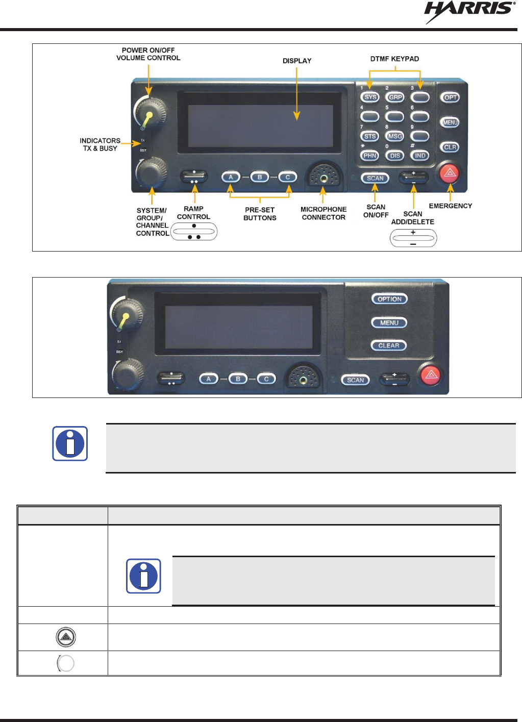
MM-014716-001, Rev. P
78
Figure 7-1: System Model
Figure 7-2: Scan Model
Button function may vary depending upon
radio
programming. Complete the table in
S
ection 10 if the keys have been remapped to provide new functions.
Table 7-1: Front Panel Default Controls and Functions
PART
FUNCTION
Power On
-
Off/Volume
Contro
l knob
Turn knob clockwise to power on the radio and increase volume.
Turn counter
-clockwise to decrease volume and power off the radio.
The radio can be programmed to require the entry of a PIN in order to
operate the radio. Check with your System Administrator if you forget your
PIN. As the PIN is entered, an asterisk is displayed for each digit. The actual
value is not displayed.
Mic
Connection
Connection for hand
-held, hands-free, speaker-mic, headset, or programming cable.
The Emergency button
declares an emergency if enabled through programming.
This rotary switch selects the systems or groups/channels, depending upon programming.
NOTE
NOTE

MM-014716-001, Rev. P
79
PART FUNCTION
This rocker type button is used to display the current SCAN status for a group/channel and
then add or delete the group/channel from the system scan list.
The primary function of this rocker type button is to scroll through the System list or the
Group/Channel list depending upon programming.
The secondary function is to increment or decrement items within a list (phone list for
example).
OPT/OPTION
Toggle a PC programmable feature ON and OFF.
CLR/CLEAR
Exits the current operation or entry mode.
In Conventional mode, pressing this button unmutes the receiver so activity on the selected
channel can be monit
ored.
MENU
Primary function
-
access the menu list. This is a list of additional features that are not
available directly from the keypad.
Secondary function
- activate a selected item within a list, similar to an enter key.
SCAN
Toggles scan operation O
N and OFF.
Pre-
Set buttons
A
,
B
,
C
Used to store and recall user
-selectable parameters.
SYS
Used to enter the System select mode.
GRP
Used to enter the Group select mode.
STS
Permits the transmission of a pre
-programmed status message to an EDACS or P
25 Trunked
site.
MSG
Permits the transmission of a pre
-
programmed message to an EDACS or P25 Trunked site.
PHN
Used to place telephone calls through the radio by selecting the interconnect special call
function.
DIS
Used to show the key ID and whether o
r not it is valid or available.
IND
Used to call an individual or make an all
-call by selecting the individual call function.
7.3 KEYPAD LOCK/UNLOCK
1. Scroll through the menu until “KEY LOCK” is displayed.
2. Press MENU.
Press MENU and OPTION to unlock the keypad.
7.4 PRESET BUTTONS
Any button on the control head can be programmed as a preset button. When programmed as a preset
button, press and hold that button for approximately three (3) seconds to store the following information
to the function of that button:
x Currently selected Priority 1, Priority 2, and Priority 3 talk groups
x Currently selected talk group
x Scan state
After changing systems, groups, or scan state, simply press the preset button to restore these settings.
Presets are saved and restored to/from non-volatile memory. Changing control heads does not recall
presets for the previous control head.
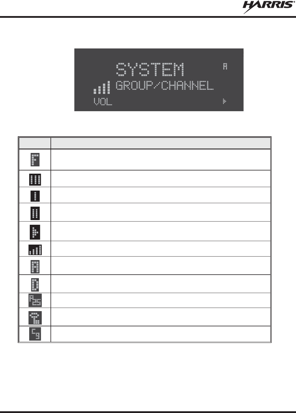
MM-014716-001, Rev. P
80
7.5 RADIO STATUS ICONS
Status icons are indicators that show the various operating characteristics of the radio.
Figure 7-3: Typical Display
Table 7-2: Icons and Descriptions
ICON
DESCRIPTION
Indicates the EDACS system is in Failsoft™ mode (if enabled through
programming).
Indicates selected group or channel is i
n the scan list.
Indicates selected group or channel is programmed as Priority 1 in scan list.
Indicates selected group or channel is programmed as Priority 2 in scan list.
Indicates
scan mode enabled.
Volume bars
– indicate relative volume level.
Indicates the current channel is set up as an analog channel.
Indicates the current channel is set up as a ProVoice channel.
Indicates the current channel is set up as a Project 25 (P25) channel.
Indicates
receiving or transmitting encrypted calls.
Indicates a conventional channel enabled with Channel Guard Function.

MM-014716-001, Rev. P
81
7.6 MESSAGES
During radio operation, various messages are displayed on either line 1 or line 2. Typical messages
include control channel status information, such as system busy or call denied, or messages associated
with the radio's operation, (i.e., volume adjust). These messages are described as follows:
Table 7-3: Radio Messages
MESSAGE
NAME DESCRIPTION
QUEUED
Call Queued
Indicates the system has placed the call in a request queue.
SYS BUSY
System Busy
Indicates the system is busy, no channels are currently available, the queue is full or an
individual call is being attempted to a radio that is currently transmitting.
DENIED
Call Denied
Indicates the radio is not authorized to operate on the selected system.
CC SCAN
Control Channel Scan
Indicates the control channel is lost and the radio has entered the Control Channel Scan mode
to search for the control channel.
WA SCAN
Wide A
rea Scan
Indicates the control channel is lost and the radio has entered the Wide Area Scan mode to
search for a new system (if enabled through programming).
T99 ON
Type 99 Decode ON
Indicates the Type 99 Decode feature is enabled.
T99 OFF
Type 99 Decode OFF
Indicates the Type 99 Decode feature is disabled.
*RXEMER*
Receive Emergency
Indicates an emergency call is being received. This message is flashing on line 2.
*TXEMER*
Transmit Emergency
Indicates an emergency call has been transmitted. This message is flashing on line 2.
VOL=31
Volume Level
Indicates the current volume level. The volume level display ranges from OFF (silent) to 40
(loudest).
UNKNOWN
Caller's ID Not Received
Indicates that an individual call is being received, but the caller's ID was not received.
DATA T/R
Transmit/Receive Data
Indicates the radio is transmitting/receiving a data call.
DATA OFF
Data OFF
Indicates the radio is in the data disabled state. Displayed on line 1.
DATA ON
Data ON
Indicates the radio has been toggled to the data enable state. Displayed for two seconds on
line 1 when toggled to enable state.
SYSC ON
System Scan Features
ON
Indicates the System Scan features are enabled.
SYSC OFF
System Scan Features
OFF
Indicates the System Scan features are disabled.
PA ON
Public Address ON
Indicates that the public address function of the radio is enabled.
PA OFF
Public Address OFF
Momentary (2 seconds) - indicates that public address function of the radio was disabled.
ALRM ON
External Alarm Enabled
Indicates that the external alarm function of the radio is enabled.
ALRM OFF
External Alarm Disabled
Momentary (2 seconds) - indicates that the external alarm function of the radio was disabled.
PVT DIS
Private Mode Disabled
Indicates that private mode is disabled or no encryption key has been programmed for the
selected group/channel or special call.
FRCD PVT
Forced Private
Operation
Indicates that forced private operation has been pre
-programmed into radio.
NO KEY #
Encryption Key Missing
Flashing - indicates that no encryption key or an incorrect encryption key is programmed into
the radio.
BCKL=1-6
Backlight
Indicates the display intensity and keypad backlight level.
GR
Group ID
Indicates that the call is a group call and is followed by the GID of the caller.
ID
Individual ID
Indicates the call is an individual call and the ID number of the caller, example "ID 2725."
WHC=1
Who Has Called
This display indicates the number from the Who Has Called list. Individual calls received but
not responded to are stored in a
Who Has Called
list. This list is accessible by pressing the #
key and then the INDV key after the Individual call has timed out or the Clear button is
pressed. This display is on line 2 and the LID of the caller is displayed on the top line.
Currently the list is not implemented and the display is always WHC=1.

MM-014716-001, Rev. P
82
MESSAGE
NAME DESCRIPTION
PHONE
Phone Call
Displayed when a phone call is received from the site. It is displayed in line 1 of the display.
Line 2 of the display contain
s the display *INDV* when line 1 contains this messag
e. The radio
interprets a received phone call as an individual call.
CONV FS
Conventional Failsoft
Displayed when a failure of the EDACS system occurs. All communication is in conventional
mode.
MENU
Displayed when the menu key is pressed and remains displayed in line 1 until a menu item is
selected.
SYS=1
-64
System = 1
- 64
The system number for the current base station of the system displayed in line 1. It is
displayed in line 2 of the display. Press the system key to obtain this display.
GRP=1
-64
Gr
oup = 1 - 64
The group number of the group displayed in line 2 of display. It is displayed in line 1 of the
display. Press the group key to obtain this display. There are up to 48 groups available (i.e., 3
banks of 16). The maximum number of groups programmed in a radio is determined by the
personality.
INDV=1
-99
Individual = 1
- 99
Indicates which item in the individual call list is being displayed. It is displayed in line 2 of the
display. The name or ID of the item in the list is displayed in line 1 of the display.
PHN=1
-99
Phone = 1
- 99
Indicates which item in the phone list is being displayed. It is displayed in line 2 of the display.
Line 1 of the display is the last 3 characters of the list item contents.
SEL PHN
Select Phone
After pressing the PHN key, selecting an entry from the phone list by typing the entry number
displays this message on Line 1.
SEL INDV
Select Individual ID
Displayed on line 1 when an entry from the individual ID list is selected after pressing the INDV
key. The entry is a number between 1 and 32 inclusive.
SYS ALL
System All Call
Displayed on line 1 to indicate a system all-call has been received.
Ggg
-v.vv
Code Group and
Revision Number
This is code group and revision number that is displayed in line 2 when the menu item
“REVISION” is selected. The ‘gg’ is the group number of the software. The first ‘v’ is the
hardware version and ‘vv’ is the revision of the software.
*PHONE*
Phone Call
Displayed when an initiated phone call is in progress. This is displayed on line 2 of the display.
NO ENTRY
Indicates that there is no data stored in one of the programmable items in either the phone list
or individual call list. The user programmable items are items 1 through 10 in each list.
INV SYS
Invalid System
Displayed when the current system is an invalid type.
CHN=1
-99
Channel = 1
- 99
Displayed on line 1 of the display. This is a conventional channel index displayed when the
group key is pressed.
FIX LIST
Fixed List
The Priority scan list is fixed and cannot be changed using the add or delete keys.
FIXED P1
Fixed Priority 1
The Priority 1 scan channel is fixed and cannot be changed using the add or delete keys.
EM
Emergency
Indicates an emergency has been declared by the LID that follows the display, “EM.” An
example of this is “EM 01201.”
*INDV*
Individual Call
Displayed in line 2 of the display when an individual call is in progress.
*GROUP*
Group Call
Indicates a group call is in progress and is displayed on line 1 of the display.
SPKR ON
External Speaker ON
Displayed when the external speaker is enabled.
SPKR OFF
External Speaker OFF
Displayed when the external speaker is disabled.
BANK=1
-8
The bank of keys that are going to be loaded when the keyloader loads encryption keys. This
is only valid for radios that support VGS, VGE, or DES encryption. It is displayed on line 2 of
the display when the encryption keyloader is connected.
REGR_0x
Dynamic Regroup
Indicates which group in the dynamic regroup operation has been enabled, where “x” is a digit
of 1 to 8.
KEY LOAD
Displayed on line 1 of the display when the encryption keyloader is connected.
KEY ZERO
Displayed on line 2 of the display when the reset and option buttons are pressed
simultaneously for approximately two seconds. The encryption keys are zeroed.
SYS KEY
System Key
Displayed on line 1 of the display in the display key mode of the menu. It is followed in the
second line with a key number “KEY = <1..7>.”
GRP KEY
Group Key
Displayed on line 1 of the display in the display key mode of the menu for trunked systems
only. It is followed in the second line with a key number “KEY = <1..7>.”

MM-014716-001, Rev. P
83
MESSAGE
NAME DESCRIPTION
KEY=1
-7
Displayed on line 2 of the display in the display key mode of the menu for conventional
systems when the “SYS KEY” or “CHN KEY” is displayed in line 1 and for trunked
systems
when the “SYS KEY” or “GRP KEY” is displayed in line 1.
PRIMARY
Displayed on line 1 of the display when the primary keys are enabled.
PRS NAME
Personality Name
Displayed on line 1 of the display under the revision selection of the menu. The personality
name is displayed on line 2 at the same time.
BND SCAN
Band Scan
Only displayed if the P25T system is configured for "EnhancedCC" mode of operation.
When the radio cannot find a Control Channel in either the trunked frequency set or the list of
d
iscovered adjacencies, t
he radio is able to perform a full spectrum frequency scan to find a
new Control Channel.
REGISTER
Displayed when the radio is performing a registration/affiliation on a P25 trunking site.
7.7 ALERT TONES
The XG-75M/M7300 series mobile radio provides audible alert tones to indicate the various operating
conditions. These alert tones can be enabled or disabled through programming.
Table 7-4: Alert Tones
NAME
TONE
DESCRIPTION
Call Originate
One short mid-
pitched tone
Sounds after the PTT button is pressed. Indicates the radio has been assigned a
working channel.
Autokey
One
mid-
pitched
tone
After being placed in a queue or releasing the PTT button prior to a working channel
assignment, the
site calls the radio when a channel becomes available. At this point,
the radio automatically keys the transmitter (autokey) for a short period to hold the
channel. The radio sounds a mid
-
pitched tone when it is clear to talk. Immediately
press the PTT button to keep the assigned channel.
Call Queued
One
high-
pitched
tone
Sounds after pressing the PTT button indicating the system has placed the call request
in the queue. The receiving unit(s) also sound(s) the tone to indicate they will receive a
call shortly.
System Busy
Three low
-
pitched
tones
Sounds if the radio is keyed when the system is busy, if no channels are available for
sending the message, if the call queue is full, or if an individual call is being attempted to
a radio that is transmitting.
Call Denied
One low-pitched
tone
Indicates the radio is not authorized on the system that has been selected.
Carrier
Control Timer
Five short high-
pitched tones
followed by a
long low
-
pitched
tone
Sounds if the programmed time for continuous transmiss
ion is exceeded.
The
transmitter shut
s
down shortly after the alert, interrupting communications. Release and
re
-key the PTT button to maintain communications. This resets
the carrier control timer
and turn
s the transmitter back on.
Key Press
Alert
A shor
t tone
Indicates a key has been pressed. A short low-pitched tone indicates no action was
taken because the key is not active in the current mode.
Page
(P25T Only)
Three high-
pitched tones
In P25 trunked mode, if the receiving radio accepts a page, both the receiving and
transmitting radios emit three high-pitched tones.
Out of Range
One low pitched
tone
Indicates the radio is in Wide Area Scan. The radio periodically beeps when in Wide
Area Scan.
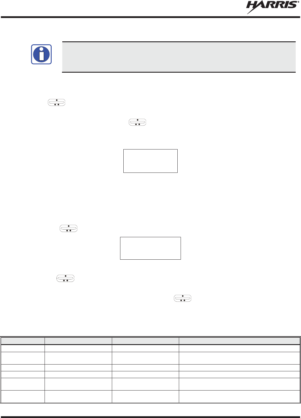
MM-014716-001, Rev. P
84
7.8 MENU
To directly access a
menu, press the correspond
ing button on the control head. For
example, press the
SYS button to enter the System select mode.
Button configuration
may vary depending on radio programming.
The order and specific number of menu items available is configurable through programming. Upon radio
power up, the menu item at the beginning of the menu list is always displayed first. Subsequent access to
the menu function returns the last menu item shown in the display. To enter the menu mode, press
MENU. and CLR are used during the selection process. The radio continues to receive and
transmit normally while in the menu function.
A new item is displayed by using the ramp control to scroll through the list in increasing and
decreasing order. The displayed menu item is made active by pressing MENU.
After entering the menu, the following generic display format appears.
M E N U
Y Y Y Y Y Y Y Y
Line 1 indicates the radio is in the menu. Line 2 indicates the menu item (YYYYYYYY) that is to be
viewed or changed (some menu items provide radio information and do not have changeable parameters).
An example of the menu item selection process and menu item parameter change is detailed below for the
brightness menu item.
1. Press MENU to enter the menu mode.
2. Press the ramp control until the display shows:
M E N U
BACKLGHT
3. Press MENU.
4. Use the ramp control to increase or decrease backlight brightness. Once the desired setting is
reached, press MENU to store the value and return to the normal display.
5. For menu items that display radio information, use to scroll through a list of informational
displays.
The menu items are listed in Table 7-5.
Table 7-5: Menu Item Information
FEATURE
DISPLAY
PARAMETER SETTINGS
COMMENT
Backlight Adjust
Menu Item: BACKLGHT
Sets the backlight level.
Radio Revision
Information
Menu item:
REVISION
Informational displays only; no
user selectable settings.
Selects the information display to view.
Phone Call
Menu item: PHONE
Allows access to the Phone Call Feature.
Individual Call
Menu Item: INDV
Allows access to the Individual Call Feature.
External Alarm
Menu Item:
EXTALARM ON, OFF
EXTALARM replaces the system name on the display as
long as the external alarm feature is enabled.
Public
Address
Men
u item: PUB ADDR ON, OFF
Public Address is toggled ON and OFF.
NOTE

MM-014716-001, Rev. P
85
FEATURE
DISPLAY
PARAMETER SETTINGS
COMMENT
External Speaker
Menu item: EXT SPKR
ON, OFF
External Speaker is toggled ON and OFF.
Encryption Key
Loading
Menu item:
KEYLOAD
Up to 8 banks of 7 keys
Enables the radio to accept the loading of encryption
keys.
Display Current
Encryption Key(s)
Menu item:
DISP KEY
Displays current encryption key number.
Scan
Menu item: SCAN
ON, OFF
Toggles scan function ON or OFF.
Private Mode
Menu Item: PRIVATE
ON, OFF
Toggles private function ON or OFF.
Scan Add
Menu item: SCAN ADD
III, II, I
Adds group or channel to scan list.
Scan Delete
Menu item: SCAN DEL
Deletes group or channel from scan list.
Scan Add/Delete
Menu item:
SCAN A/D
Toggle sequence
III, II, I
Changes present group or channel to next scan choice
in scan list.
Last Scanned
Channel Recall
Menu Item:
SCAN ADD
Changes the selected channel to the last scanned
channel.
Home group or
channel selection
Menu item:
HOME
Changes to the group or channel defined for Home
function.
System select
Menu item: SYS
Displays the system selected.
System and group
selection
Menu item:
S/G 1 – S/G 16
Changes to the System & Group/Channel programmed
for SYSGRP 1-16.
Mute
Menu item:
MUTE ON, OFF
Toggles the mute function ON or OFF to control the
audio output from the selected radio.
No Data
Menu item: NO DATA
ON, OFF
Toggles data feature ON or OFF.
EDACS
Conventional
Priority 1 Scan
Menu item:
ECP1 SCN ON, OFF
Toggles this feature ON or OFF.
Group selection
Menu item: GRP
Displays the group selected.
Status Condition
Menu item:
STATUS
0-9 = (n)umber of pre-
programmed status
Transmits the pre
-programmed status message.
Message Condition
Menu item:
MESSAGE
0-9 = (n)umber of pre-
programmed messages
Transmits the pre
-programmed message.
Feature
Encryption
Display
Menu Item:
FEATURES
Informational displays only; no
user selectable settings
Indicates current features programmed into the radio as
well as certain information required to add features to
the radio.
System Scan
Enable
Menu Item:
SYS SCAN ON, OFF
System Scan features like ProScan are toggled ON and
OFF.
Talkaround feature
Menu item:
TALK ON, OFF
Toggles Talkaround ON or OFF (transmit frequency
changed to receive frequency).
Type 99 Decode
Enable
Menu Item:
T99 EN ON, OFF
Type 99 Decod
e is toggled ON and OFF.
Display GPS
information
Menu Item:
GPS
Informational displays only; no
user selectable settings
Displays GPS Status (On/Off), Latitude, Longitude,
Speed/Direction, and time. See Section 7.38.
Select Mixed
System/Zone
Menu Item:
ZONE
Select a Mixed System Zone.
See Section 7.19.
Display Caller ID
Menu Item:
CALL ID
Informational displays only; no
user selectable settings
Displays the Radio IDs or alias names for the last 10
received calls. See Section 7.20.
View/Modify
Custom Scan List
Menu Item:
CUSTSCAN
Allows you to view and edit a Custom Scan list. See
Section 7.23.7 for more information.
7.9 FEATURE ENCRYPTION DISPLAY
Feature Encryption Display is available through the menu function and, if programmed, appears in the
menu as “FEATURES.” This data indicates current features programmed into the radio as well as
information required to add features to the radio.
Once the feature has been accessed, all normal menu functions work. The user can scroll up or down
through all of the entries.
Feature Encryption Display provides the ability to view, in the order displayed, the following:
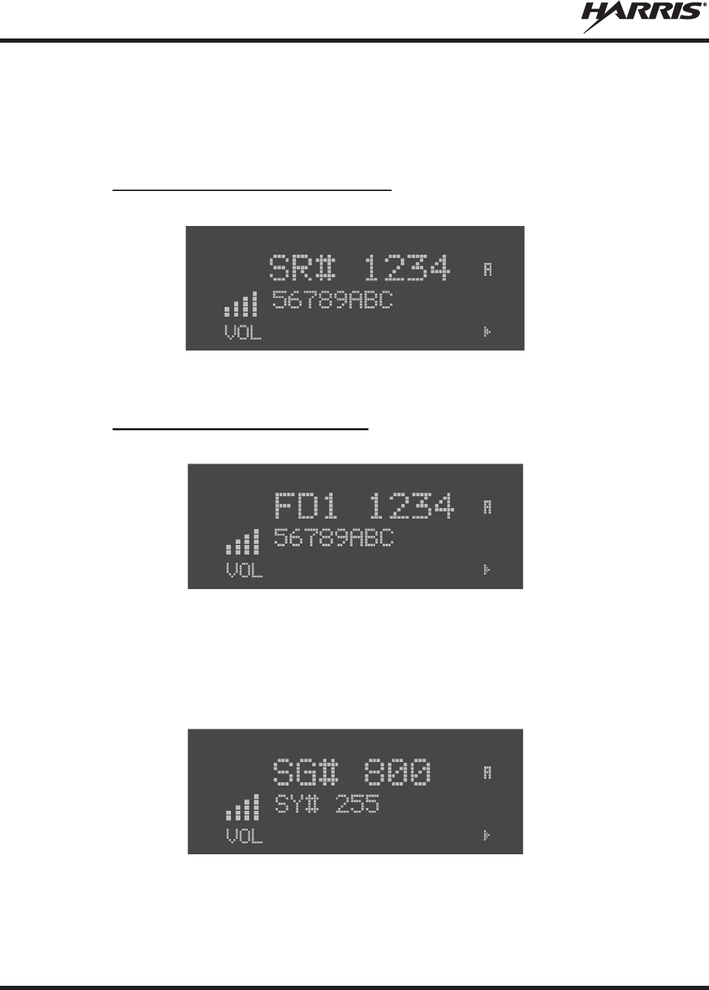
MM-014716-001, Rev. P
86
x Serial number ROM data - serial number of the ROM
x Feature encryption data stream - used to enable features
x Number Fields - defines limits
x Features enabled - displays bit fields of enabled features
7.9.1 Serial Number ROM (12 Hex Digits)
Example:
To enable a feature in a radio, call Harris and provide them with the ROM serial number. The serial
number shown here is for example only.
7.9.2 Feature Encryption Data Stream
Example:
These data streams define the features the user has enabled in his radio and are required by Harris to
enable other features. The data streams shown here are for example only. There are three displays: FD1,
FD2, and FD3. All three are required.
Number Fields
Example:
These number fields show the set limits of the user's radio as:
x SG# XXX - Maximum number of system/groups combination available
x SY# XXX - Maximum trunked system limit
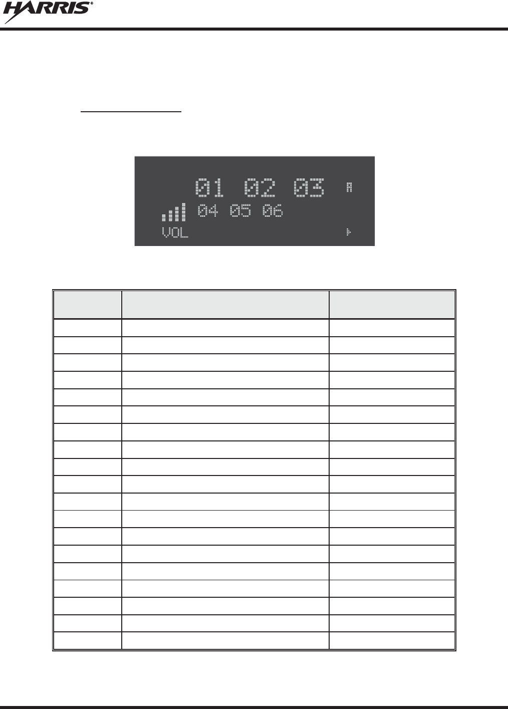
MM-014716-001, Rev. P
87
x CH# XXX - Maximum number of conventional channels available
The user needs to know the limits of the radio before attempting to enable other features. The numbers
shown here are for example only.
7.9.3 Features Enabled
These numbers indicate which features are enabled.
Example:
Table 7-6 lists possible features available in the user's radio.
Table 7-6: Available Feature Numbers
FEATU
RE
NUMBER
POSSIBLE FEATURES STANDARD OR
OPTIONAL
01
Conventional Priority Scan
Standard
04
Group Scan (EDACS and P25 Trunked)
Standard
05
Priority System Scan (EDACS and P25 Trunked)
Optional
06
W
Ascan/ProScan (EDACS and P25 Trunked)
Optional
07
Dynam
ic Regroup Standard
08
EDACS Emergency
Standard
09
Type 99 Encode
Standard
10
Conventional Emergency
Standard
14
DES Encryption
Optional
16
Mobile Data
Optional
17
Status/Message (EDACS and P25 Trunked)
Optional
21
EDACS Security Key (ESK)
Optional
22
ProFile™ (EDACS and P25 Trunked)
Optional
23
Narrowband
Standard
29
ProVoice™
Optional
32
FIPS
-140-2 Optional
33
P25 Common Air Interface
Optional
34
Direct Frequency Entry
Optional
38
Radio TextLink
Optional
MM-014716-001, Rev. P
88
7.10 VOICE ANNUNCIATION
When enabled via programming, the Voice Annunciation feature provides audible feedback for various
radio operations. The radio can be programmed to play an audio message for any or all of the following.
This message can be a pre-recorded (canned) message or a user-recorded message.
x Channel changes
x System changes
x Encryption On/Off
x Noise Cancellation On/Off
x Scan On/Off
x Talkaround On/Off
For more information on configuring the radio for Voice Annunciation, refer to the Voice Annunciation
Feature manual 14221-7200-6110.
7.11 SYSTEM/GROUP/CHANNEL SELECTION
The XG-75M/M7300 SYSTEM/GROUP/CHANNEL knob and the ramp control are
programmable for maximum flexibility. If the SYSTEM/GROUP/CHANNEL knob is assigned to select
groups or channels, then the ramp control is assigned to select systems. If the
SYSTEM/GROUP/CHANNEL knob is assigned to select systems, then the ramp control is
assigned to select groups or channels. System, group, and channel selection is the primary function for
these controls.
Systems or groups can also be selected by pressing SYS or GRP and using the ramp control to
scroll through available options.
7.11.1 System Selection
Several methods, some of which depend on programming, can be used to select a new system. These
procedures are presumed to be starting from the normal receive display.
METHOD 1:
If system selection is programmed to the SYSTEM/GROUP/CHANNEL knob, select a
system by turning the SYSTEM/GROUP/CHANNEL knob to the desired system
position. The display registers the new system name on line 1. If the wrap option
is OFF
and the knob is moved to a position greater than the number of programmed systems, the
highest programmed system remains selected.
METHOD 2:
If system selection is programmed as the primary function of the
ramp control,
select a system by pressing up or down to scroll through the system list. The display
registers the new system name on line 1.
METHOD 3:
Press
SYS to enter the system select mode and use the
ramp control to scroll
through the systems.
7.11.2 Group and Channel Selection
Several methods, some of which depend on programming, can be used to select a new group or channel.
These procedures assume starting from the normal receive display.
MM-014716-001, Rev. P
89
METHOD 1:
If group selection is programmed to the SYSTEM/GROUP/CHANNEL knob, select a
group by turning the SYSTEM/GROUP/CHANNEL knob to the desired group. The
display registers the new group name on line 2. If the wrap option is OFF and the knob
is moved to a position greater than the number of programmed groups, the highest
programmed group remains selected.
METHOD 2:
If group selection is programmed as the primary function of the
ramp control,
select a group by pressing up or down, to scroll through the group list. The display
registers the new group name on line 2.
METHOD 3:
Press
GRP to enter the group select mode and use the ramp control to
scroll
through different groups.
METHOD 4:
Press the key programmed for Channel Entry (must be programmed to a button using
RPM R10B or later). Enter the channel number. Entering a number greater than the
maximum number of entries will select the last channel. Channel changes made with
the knob are made with respect to the manually entered channel.
7.12 LAST SYSTEM/GROUP/CHANNEL RECALL
This feature, enabled through programming, allows the user to recall the last selected system/group after
an emergency or home function or system/group key function. For example, if the Home button (pre-
programmed) is pressed, the radio goes to the designated Home system/group or channel. If the Home
button is pressed again, the radio returns to the previous system/group or channel. At this time, the user
can toggle between the Home system/group or channel and the previous system/group or channel. The
operation is the same for the SG1-SG16 buttons.
7.13 ENCRYPTION
The XG-75M/M7300 mobile radio supports AES and DES encryption. When operating on a group or
channel programmed for encryption, all transmissions are private and the radio receives clear and private
signals. is displayed when encryption is enabled. If the selected group or channel is programmed for
auto-select capability, the mode may be toggled between encrypted and unencrypted by pressing the
MENU key, and then selecting the PRIVATE menu option. Radios programmed for forced encryption do
not allow a change of the transmit mode.
7.13.1 Displaying the Currently Used Cryptographic Key Number
To display the cryptographic key currently in use for either the system encryption key (for special call
such as individual, phone, all, agency or fleet) or the group/channel key (for group or conventional calls),
perform the following procedure (Not Available on Conventional radios):
1. Press the MENU button.
2. Use to select DISP KEY. Then press the MENU button.
3. Then use to toggle between displaying the system key or the group/channel key.

MM-014716-001, Rev. P
90
Table 7-7: Current Cryptographic Key Display
ENCRYPTION KEY
DISPLAYED
MESSAGE DISPLAYED
System
"SYS KEY"
"KEY = 1"
Group/Channel
"GRP KEY"/"CHN KEY"
"KEY = 2"/KEY = 2"
7.13.2 Key Zero
All cryptographic keys can be zeroed (erased from radio memory) by pressing and holding the
CLR/CLEAR button, and while still pressing this button, press and hold the OPT/OPTION button. Press
both buttons for 2 seconds. A series of warning beeps begins at the start of this 2-second period and then
switches to a solid tone after the keys have been zeroed. The display indicates KEY ZERO.
If the cryptographic key(s) are zeroed, one or more keys must be transferred from the Key Loader into the
radio before private communications can continue. Refer to Key Manager TQS3416 Administration and
Software Release Notes for further information.
7.13.3 Receive an Encrypted Call
When receiving, the radio automatically switches between clear or encrypted operation. If the
transmission being received is an encrypted transmission, it is decrypted, the receiver unsquelches, and
the message is heard in the speaker. The selected group or channel must be programmed for encryption
and the correct cryptographic key must be loaded into the radio for this to occur.
7.13.4 Transmit an Encrypted Call
1. Select the desired group or channel.
2. Enable encryption by pressing the MENU button and then selecting the PRIVATE menu option, or
press the button on the control head that has been programmed for PRIVATE.
x If the last state of the radio was encryption enabled, then encryption is enabled on power up. In
addition, encryption is enabled if forced operation has been programmed in the radio
x If a group or channel is not programmed for encryption, PVT DIS is displayed if an attempt is
made to enable encryption. It is not possible to operate on this group/channel in encrypted mode.
x If the radio is programmed for forced encryption mode, FRCD PVT is displayed if an attempt is
made to disable encryption. It is not possible to transmit on this group/channel in clear mode.
x If the radio does not have the correct encryption key loaded, NO KEY # is displayed and the call
does not transmit.
3. Continue with standard transmission procedures. An access tone is heard when the PTT button is
pressed.
7.13.5 Emergencies on Encrypted Group
The radio can be programmed to allow emergency calls to be transmitted in the clear when the radio does
not have the key, or has an invalid key for the encrypted group in emergency.

MM-014716-001, Rev. P
91
7.14 MACRO KEY OPERATION
Macro key operation permits the user to accomplish a series of keystrokes with a single "macro"
keystroke. Up to ten (10) macro keys can be defined, each capable of executing up to twenty (20)
keystrokes, to any pushbutton input (i.e., keypad keys, buttons, etc.). Each macro key can be pre-
programmed to activate when pressed or when released. A macro key can also be pre-programmed to
change the keystroke sequence the next time the macro key is activated. For detail operation and
assignment of macro keys, contact your system administrator.
7.15 RECEIVE A CALL
1. Turn the radio on by rotating the POWER ON-OFF/VOLUME knob clockwise (out of detent). A
short alert signal (if enabled through programming) indicates the radio is ready to use.
2. The display shows the last selected or the power up (depending on programming) system and
group/channel names. If the radio is unable to obtain a control channel, line 2 shows CC SCAN.
3. Adjust the volume to the desired level.
4. Select the desired system and group/channel.
5. The radio is now ready to receive calls.
6. When the radio receives a call, it unmutes on the assigned working channel and the BSY indicator
comes on. Line 1 shows GR followed by the logical ID number (if received) of the unit sending the
message, or the associated name if the ID number is found in the individual call list.
7.16 TRANSMIT A CALL
1. Turn the radio on and set the POWER ON-OFF/VOLUME knob to the desired volume level. Select
the desired system and group/channel.
2. Ensure that conventional channels are not busy by pressing the CLR button to briefly disable any
channel decoding and unmute the receiver, or observe the unlit BSY indicator. If the Channel Busy
Lockout feature is programmed for the selected channel, the radio does not transmit when the channel
is busy.
3. Press and hold the PTT button.
4. When the working channel is assigned, TX and BSY indicators are turned ON and a short beep is
sounded indicating communication can begin.
If two or more tones, or a high
-pitched tone, are
heard the system may be busy and the
call request has been placed in queue or the request has been denied for some reason.
Refer to the Section
7.7 for more details.
5. Hold the microphone approximately 2 inches from the mouth and speak in a normal voice.
6. Release the PTT button when the transmission is complete and listen for a reply.
7.17 CONVENTIONAL FAILSOFT (EDACS)
In the unlikely event of an EDACS system failure, communications can take place in conventional failsoft
mode. The radio is automatically directed to a communications channel set up for this purpose. During
this mode of operation, the control unit displays CONV FS in the alphanumeric display. An increase in
NOTE

MM-014716-001, Rev. P
92
activity on the channel during conventional failsoft operation may be noticed, so be careful not to transmit
until the channel is clear.
Operation during conventional failsoft is the same as operation on a conventional system, except that it is
not possible to select a communications channel, or use emergency and special call. When trunking is
restored, the radio is automatically returned to normal operation.
Emergency and Special Call are not operational during conventional failsoft. In
addition, the
GRP control does not operate.
7.18 EMERGENCY OPERATION
The radio’s emergency behavior varies depending on programming. When an emergency is declared,
scanning stops and only restarts after the emergency is cleared.
7.18.1 Receive an Emergency Call
When receiving an emergency call from the selected group and system, an alert beep sounds and the BSY
indicator illuminates. The message *RXEMER* flashes in the display on line 2 until the emergency
condition is cleared. Follow standard emergency procedures.
7.18.2 Declare an Emergency
To send an emergency call to the selected system and group (or on an optionally pre-programmed
emergency group), proceed as follows:
1. Press and hold the red emergency button for approximately one second. (This time is programmable
and could be longer or shorter. Check with the system administrator.) The radio transmits an
emergency call request with the radio ID until an emergency channel assignment is received.
2. When the working channel assignment is received, the radio sounds a single beep (Autokey alert
tone) indicating it is ready for voice transmission. *TXEMER* flashes on line 2 in the display until
the emergency is cleared.
3. Press PTT and speak into the microphone in a normal voice.
4. Release PTT when the transmission is complete and listen for a reply.
5. The emergency can be cleared by pressing and holding the CLR button followed by pressing the red
emergency button then releasing both buttons.
NOTE

MM-014716-001, Rev. P
93
7.19 MIXED SYSTEM ZONES
A Zone is a grouping of analog conventional channels, P25 conventional channels, and/or P25T or P25C
talkgroups. Mixed System Zones are defined in RPM and can be comprised of any combination of
channels/groups from multiple systems as long as the system definitions share the same WACN/System
ID. If a Mixed System Zone is not configured in RPM, it will not appear on the radio. Up to 50 Mixed
System Zones can be defined.
To select a Mixed System Zone:
1. Press MENU.
2. Scroll through menu and select ZONE.
3. Select the desired Mixed System Zone.
Alternately, the System/Group/Channel knob or a button on the radio can be programmed to scroll
through available Mixed System Zones.
When scan is enabled on a system in a Mixed System Zone, the radio continues to display the zone name
or system name per the current radio mode (system/zone). When toggling scan ON/OFF, there is no
change one line 1 of the radio display. If it is showing system name, it continues to show system name; if
it is showing zone name, it continues to show the zone name during scanning.
7.20 CALLER ID
This feature allows you to view the caller ID or alias for up to the last 10 received calls. Received calls
include Group, Announcement, Phone, Patch, SimulSelect, Agency, Fleet, and MDC.
1. Press MENU and scroll through menu to select CALL ID. Alternately, a button can be programmed
to access the CALL ID list.
2. Scroll through available entries. The most recent call is displayed at the top of the list. “NO
ENTRY” is displayed if there are no entries.
3. Caller ID or “NO ENTRY” is displayed for 10 seconds. Press the Clear button to exit the Caller ID
list.
The Caller ID list is cleared when power is cycled on the radio.
7.21 STEALTH MODE
Press the button programmed for Stealth Mode operation to toggle Stealth Mode on or off. During Stealth
Mode, all buttons are disabled except PTT, the button programmed for Stealth operation, Emergency, and
Nuisance delete. The radio will receive and transmit when Stealth Mode is enabled.
The radio can be configured to disable any or all of the following during Stealth Mode:
x LCD display
x LED
x Backlight
x Side/alert tones
Stealth Mode can be configured to persist through a power cycle.

MM-014716-001, Rev. P
94
7.22 SYSTEM SCAN OPERATION (EDACS AND P25 TRUNKED)
The radio can be programmed with the following System Scan features. These features are automatically
enabled upon radio power up. A key or menu option is also defined to allow the System Scan features to
be toggled during radio operation. This is covered in the Menu Selection and Pre-Programmed Keypad
Key sections. The System Scan state is maintained through system changes but defaults to ON at power
up.
7.22.1 Wide Area System Scan (WA Scan)
The XG-75M/M7300 Series mobile radio can be programmed for Wide Area System Scan operation for
multi-site applications. Upon the loss of the currently selected system's control channel, radios can be
programmed to automatically scan the control channels of other systems. If a new control channel is
found, the radio switches to the new system and sounds an alert tone. The amount of time before the
radio enters Control Channel Scan after losing the control channel is configurable in RPM.
7.22.2 ProScan™
The radio can be programmed for ProScan™ system scan operation for multi-site applications depending
on the version of radio flash code. ProScan provides the radio with the ability to select a new system for
the radio to communicate on, when the selected system drops below a predefined level. This is
accomplished by enabling each radio to analyze the signal quality of its current control channel and
compare it with the signal quality of the control channel for each site in its adjacency scan list. The signal
quality metric used for the ProScan algorithm is based on a combination of both Received Signal Strength
Indicator [RSSI] and Control Channel Verification [CCV] measurements. When the selected system’s
signal quality level degrades below a pre-programmed level, the radio begins to look for a better control
channel. Once a control channel that exceeds the pre-programmed parameters is found, the radio changes
to the new system and emits a tone. If the control channel is completely lost, the radio enters Wide Area
System Scanning and searches the programmed adjacent systems until a suitable control channel is found.
7.22.3 Priority System Scan
The radio can also be programmed for Priority System Scan. (To ensure that this feature operates
correctly, the control channel of the priority system must be located on channel one unless you are using
the ProScan algorithm.) The priority system is the desired or preferred system. While receiving the
control channel of the selected system, the radio periodically leaves the selected system and searches for
the control channel of the priority system at a programmable rate. The programmable rate is defined by
the value in the Priority Scan Time control, unless the ProScan algorithm is enabled as explained below.
This priority scan timer is reset each time the PTT button is pressed or when a call is received. If the
priority system control channel is found, or meets the predefined ProScan criteria, the radio automatically
switches to the priority system.
7.22.4 When Wide Area System Scan is Enabled
If the radio cannot find the control channel of the selected system and begins Wide Area System Scan, the
radio only scans for the priority system control channel if the priority system is in the WA Scan list.
7.22.5 When ProScan Is Enabled
The radio monitors the priority system and switches to the priority system if the priority system meets the
criteria defined in the “ProScan Options” dialog box. If ProScan is enabled, the rate at which the radio
scans for the priority system is defined by the System Sample Time control.

MM-014716-001, Rev. P
95
7.22.6 Menu Selection
Press MENU and then use the ramp control to scroll through the selections until SYS SCAN is
displayed. Then press MENU to toggle the System Scan state. The SYSC ON or SYSC OFF display
message is displayed for two seconds to show the new state.
7.22.7 Pre-Programmed Keypad Key
Press the pre-programmed key and the SYSC ON or SYSC OFF display message is displayed for two
seconds to show the new state.
7.23 SCAN OPERATION
Only groups or channels that are part of the radio's scan list are scanned. Groups/channels are added to the
scan list on a per system basis through programming, the radio keypad, or both, dependent upon
programming. This scan list can be changed by the user from the keypad, unless programmed otherwise.
Each system's scan list is retained in memory when the radio is turned off. The XG-75M/M7300 Series
mobile radio can also be programmed to provide Trunked Priority Group Scan capability, which operates
similar to priority scan in Conventional mode.
The following is a description of programmable scan features that should be helpful in understanding the
scan operation of the radio:
Scan Hang Time - the delay time the radio waits before resuming scan after the push-to-talk is released
or after the carrier has dropped a channel.
TX Select - the group the radio transmits on while scanning. The radio is programmed to transmit on
either the scanned group or the selected group.
Scan List (privileges) - this feature allows or prohibits scan list changes by the user.
P1 Programming - priority group programming is accomplished by one (and only one) of three methods:
x From the keypad, where the Priority programming is not fixed and does not follow the selected
channel.
x Priority 1 group programming follows the selected channel.
x Priority 1 group programming is fixed during PC programming and cannot be changed by the user.
P1 Always Scan - determines if the Priority 1 Group is always scanned, regardless of the scan state set by
the user.
7.23.1 Add Groups or Channels to a Scan List
1. With scan operation turned off, select the desired group channel to add to the selected scan list.
2. Press (+) or (-) with to display the current priority status of the group on line 1 for a time-out
period.
3. While the status is displayed, press (+) with to add the group/channel to the scan list. is
displayed.
4. Press (+) with a second time to set the group/channel to Priority 2. is displayed.
MM-014716-001, Rev. P
96
5. Press (+) with a third time to set the group/channel to Priority 1. is displayed in column 1,
line 1.
The priority level selection sequence only advances the group to the next higher priority level and stops at
priority level 1. To select a lower priority level, the group/channel must be deleted from the scan list and
then added back to the scan list. Each new group/channel added to the scan list starts at the lowest
priority. If the Priority 1 and Priority 2 group/channel are already set and a new group/channel is assigned
as Priority 1 or Priority 2, the previously assigned group/channel changes to non-priority scanning.
7.23.2 Delete Groups or Channels from a Scan List
1. With scan operation turned off, select the desired group/channel to delete from the selected scan list.
2. Press (+) or (-) with . The current scan status of the group/channel is displayed for a time-out
period.
3. Press (-) with to delete the group from the scan list. , or turns off. Any group/channel
that is not in a scan list shows a “blank” when it is the selected group/channel.
7.23.3 Nuisance Delete
A group/channel can also be deleted from the scan list, if it is not the currently selected group/channel, by
pressing (-) with during scan operation while the radio is displaying the unwanted group/channel.
The group/channel is deleted from the scan list in the same manner as if using the steps above. Deletions
performed in this manner do not remain deleted if the radio is turned off and back on.
7.23.4 Turn Scan On
1. Toggle scan operation by pressing SCAN. The SCAN indicator turns on when the radio is scanning.
Scanning stop
s while the microphone is off-hook if th
e hookswitch feature is enabled
through programming.
2. When a group on the scan list receives a channel assignment, the radio unmutes on the assigned
channel, the BSY indicator comes on and the received scan group is displayed.
x The radio continues scanning if a new group/channel is selected when scan is on.
x Pressing the PTT button when scan is on causes the radio to transmit on the displayed
group/channel or on the currently selected group depending on programming.
x Pressing up with when scan is on causes the radio to recall the scanned group/channel that
was last received. This group/channel is recalled for a period equal to the scan hang time.
NOTE

MM-014716-001, Rev. P
97
7.23.5 Priority Group/Channel Scanning
When scan is enabled and the Priority 1 and Priority 2 groups/channels have been identified, the radio
listens to calls on those groups/channels and the selected group/channel. While receiving a scanned call,
the radio continues to monitor the selected Priority 1 and Priority 2 group/channel and drops the call if the
selected group/channel or other higher priority call becomes active. During a Priority 2 call, the radio
continues to monitor for a Priority 1 group call.
The radio monitors for Agency and Fleet calls that correspond to the Agency and Fleet associated with
the Priority 1 and Priority 2 groups. Priority Agency and Fleet calls are indicated by displaying AGENCY
or FLEET on the System line of the display and associated Priority 1 or 2 group on the Group line of the
display.
7.23.6 Turn Scan Off
Turn scan operation off by pressing SCAN. The radio resumes operation on the selected group/channel.
7.23.7 Mixed Zone Scan
The Mixed Zone Scan (MZS) feature gives the user the capability to scan based on a custom scan list that
is assigned at the system level. The Custom Scan (CS) list can contain System and Channel/Group
configurations across P25 Trunk, P25 Conventional, and Analog Systems. When a Custom Scan List is
defined on a P25T system, the radio can scan P25T, P25C and Analog systems. When defined on a P25C
or Analog system, the radio only scans conventional channels. MZS also gives the user the capability to
scan beyond the selected system group set.
x P25T Scan
When a custom scan list is assigned to a P25T system, the user has the ability to scan P25T, P25C,
and Analog groups/channels. All P25T systems must have the same WACN, System ID, and Unit ID
to be added to the custom scan list.
x P25C and Analog Scan
When a custom scan lists is assigned to a P25C or Analog System, the user has the ability to scan
P25C and Analog channels. P25T systems are ignored.
7.23.7.1 Custom Scan List Selection
The Custom Scan List is assigned at the System level. Scanning protocols (Custom Scan, System Scan,
and Conventional Priority Scan) are mutually exclusive. Once a custom scan list is assigned to a system,
when you enable scan, you are scanning the channel/groups defined in the custom scan list. A Custom
Scan List can be assigned to a system through RPM only. The radio supports up to 10 Custom Scan lists,
with up to 50 channels/groups in each.
7.23.7.2 View Custom Scan Lists
Scan must be off to view a Custom Scan List.
1. From the radio menu, select CUSTSCAN.
NOTE
MM-014716-001, Rev. P
98
2. Select the desired group/channel from the Custom Scan list. Options available for each
channel/group include:
x View the channel’s/group’s scan priority.
x Delete the channel/group from the scan list.
x Nuisance delete the channel/group.
3. Press the Option button to back up one display; press the Clear button to return to the home screen.
7.23.7.3 Edit Custom Scan Lists
Scan must be off to edit a Custom Scan List.
1. From the radio menu, select CUSTSCAN.
2. Select EDIT LST.
3. Select the desired system from the list.
4. Select the desired channel group. Scroll through available options:
x Add the channel/group to the scan list.
x Change the channel’s/group’s scan priority.
x Delete the channel/group from the scan list.
x Nuisance delete the channel/group.
5. Press the Option button to back up one display; press the Clear button to return to the home screen.
7.24 INDIVIDUAL CALLS (EDACS AND P25 MODES)
7.24.1 Receive and Respond to an Individual Call
When the radio receives an individual call, it unmutes on the assigned working channel and turns on the
BSY indicator. Line 1 shows “ID” followed by the logical ID number of the radio sending the message,
or the associated name if the ID number is found in the individual call list. The individual call indicator
displays *INDV* on line 2. The radio can be programmed to ring when an individual call is received. If
enabled, the ring begins five seconds after the caller unkeys and continues until the PTT button, the CLR
button, or IND is pressed.
Hookswitch functions the same as
CLR key in I-
CALL, phone call, and menu modes.
If a response is made to the call prior to the programmed call-back time-out, the call is directed to the
originating unit. If a response is not made before the call-back time-out, the radio returns to normal
receive mode, but * WHC * is displayed. If the caller's ID is not received, UNKNOWN displays for the
duration of the call and there is no call-back hang time.
NOTE
NOTE
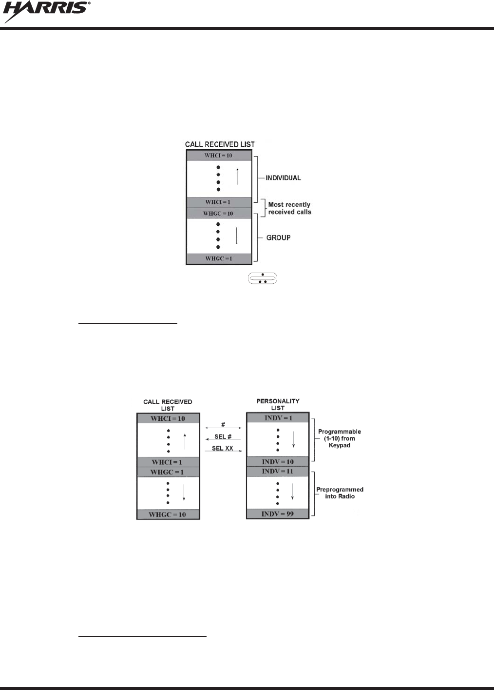
MM-014716-001, Rev. P
99
To respond after the call-back time-out, press the IND key. The radio's display shows the callers ID on the
first line and WHCI=1 on the second line. Pressing the PTT button at this point initiates an individual call
back to the original caller. (If the last call was a group call, the display shows WHCG=1. Pressing the
PTT button places the call as an individual call.)
The radio stores the IDs of the last 10 callers in the Calls Received List as shown. Individual calls are
stored in the top half of the list (1-10) and group calls are stored in the bottom half of the list (1-10). The
most recent call is stored in position 1, the second most recent call is stored in position 2, etc.
To access the list, press the IND key twice. Use to scroll through the list. Press the MENU key to
display the time elapsed since the call was received.
7.24.2 Call Storage Lists
There are two lists available for call storage in the radio; the calls received list (1-10) and the personality
list (1-99 as defined by the user). When the individual call mode is entered by pressing IND, the calls
received list is available. The user can toggle to the personality list by selecting any key other than DIS or
toggle between the two lists by pressing the IND key. If wrap is enabled, the calls received list wraps on
itself and not into the other list.
The saved call list shows all ten storage locations. If no calls have been received, the saved call list is
empty and the pre-stored list is available upon entering the individual call mode.
When in the saved call list, pressing MENU toggles the time stamp ON and OFF. The time stamp
indicates how long ago the call was received. The display indicates this information as HH:MM:SS where
HH = hours, MM = minutes, and SS = seconds.
When in the pre-stored list, pressing MENU toggles the logical identification (LID) ON and OFF.
7.24.3 Send an Individual Call
The following procedures describe how to initiate and complete an individual call:

MM-014716-001, Rev. P
100
1. To select a previously stored individual, select the I-Call mode from the menu or press IND followed
by the ramp control to scroll through the list of stored individuals. While in the individual call
list, the MENU key toggles the display between the call name and the unit ID number. If the
individual is not stored in this list but the individual’s unit ID is known, it can be entered directly
from the keypad.
2. Press the PTT button. The radio performs the necessary signaling to obtain a communication channel.
When the signaling is complete and the radio is clear to transmit, the TX indicator turns ON and the
channel access tone sounds. Line 1 shows the called individual's name if found in the list of stored
individuals or ID followed by the logical ID number of the unit being called. The message *INDV*
displays on line 2. Proceed with the message.
7.25 SCAT™ OPERATION
A SCAT (Single Channel Autonomous Trunking) System operates with the same set of features as a
standard EDACS system. The only significant user change relates to the BSY indicator. Since only one
channel, operating as both control and working channel, exists in a SCAT System, the BSY indicator is
ON when the SCAT channel is in the working channel mode. When the transmission on the channel is
completed, the indicator turns OFF and indicates the return of SCAT control channel signaling.
7.26 TELEPHONE INTERCONNECT CALLS (EDACS AND P25)
7.26.1 Receive a Telephone Interconnect Call
Receiving a telephone interconnect call is identical to receiving an individual call. See the DTMF
Overdial Operation section if access to services requiring "over-dial" is needed. Overdial operations are
available for any special call whether it is an individual call or a telephone interconnect call.
7.26.2 Send a Telephone Interconnect Call
Use the following procedures to initiate and complete a Telephone Interconnect call:
1. To select a previously stored phone number, select phone call mode from the menu, press PHN and
use the ramp control to scroll through the list of stored phone numbers. While in the phone
call list, the MENU key toggles the display between the phone call name and the phone call number.
If the phone number is not stored in this list but the phone number is known, it can be entered directly
from the keypad. If necessary, a pause can be entered by pressing and holding 0-9, (*), or (#) until an
underscore appears in the display.
2. Press and release the PTT button; the radio performs the necessary signaling to obtain a
communication channel. When the signaling is complete and the radio is clear to transmit, the TX
indicator turns on and the channel access tone sounds. Line 1 shows the accompanying name if
selected from the list of stored numbers or the phone number if entered directly. The message
*PHONE* is displayed on line 2. The radio then automatically transmits the programmed number
stored in the special call queue.
3. Telephone ringing is heard. When someone answers the phone, press the PTT button and speak into
the microphone. Release the PTT button to listen to the caller. Unsuccessful interconnect signaling
returns the radio to the normal receive mode and the number remains displayed until the special call is
cleared by pressing the CLR button or the time-out expires or another group or system is selected.
4. To terminate the call, momentarily press the CLR button.

MM-014716-001, Rev. P
101
The XG-75M/M7300 Series mobile radio is capable of half-duplex conversation only.
The caller’s message can only be sent if the PTT button is pressed (the radio is
transmitting) and the caller can only be heard by the person being called when the PTT
is released (the radio is receiving).
7.26.3 DTMF Overdial/Conventional Mode Telephone Interconnect
Once the radio has established a connection to the public telephone system, it may be necessary to "over-
dial" more digits to access banking services, answering machines, credit card calls, or other types of
systems that require DTMF (Dual-Tone Multi-Frequency) access digits. Overdial operation can also be
used to initiate a telephone interconnect call via DTMF signaling if a dial tone has already been accessed
on the system. This is the method that is used for making a telephone interconnect call while operating in
the conventional mode but also functions in trunked mode if a dial tone is directly accessible. Telephone
numbers and other number sequences for overdialing can be stored in the phone list when programming
the radio or stored by the operator in the first ten phone list entries. These numbers are accessed by
pressing PHN.
The following steps are required to dial these numbers:
1. Follow the procedure in Section 7.26.2 to establish a connection to the telephone system or consult
the system administrator for the procedure to access a dial tone on the trunked or conventional
system.
2. Overdial numbers are transmitted using either method as follows:
METHOD 1:
Press and hold PTT while entering the overdial number sequence from the keypad.
This method sends DTMF tones during individual, telephone interconnect, trunked
group, or conventional channel calls. Anytime the PTT button is pressed and held,
the keypad is enabled for DTMF entry.
METHOD 2:
Press
PHN to access
a stored number from the phone list or to directly enter the
overdial digits. Press PTT to send the overdial sequence once. If the number needs to
be transmitted again it must be selected or entered again (this prevents unwanted
numbers from being sent the next time the PTT button is pressed during the call).
This overdial select/entry mode remains active until the call is dropped, cleared, or MENU is pressed. The
overdial select/entry mode can be re-entered if the call is still active by pressing PHN.
7.26.4 Programmable Entries
Individual call ID numbers, telephone numbers and other number sequences for overdialing are stored in
the special call lists when programming the radio. The first ten entry locations of these lists can be
changed by the radio operator. The keypad is used when adding, changing, and storing numbers in these
entry locations.
Use the following procedure to store a number in one of the first ten entries of a special call list:
1. Press IND or PHN to enter the individual call list or the phone call list.
2. Scroll through the list using the ramp control until one of the first ten (10) entries is reached.
NO ENTRY is displayed if the location is empty.
3. Enter the desired number. If necessary, a pause can be entered by pressing and holding 0-9, (*), or (#)
until an underscore appears in the display. The individual call list entries accept up to 5 digits. The
phone call list entries accept a combination of up to 31 digits and pauses.
NOTE
MM-014716-001, Rev. P
102
4. Press and hold MENU until the display changes indicating that the number has been stored.
5. Repeat the steps above if the number stored in an entry location needs to be changed.
7.27 MOBILE DATA (EDACS AND P25 TRUNKED)
The XG-75M/M7300 Series mobile radios, when operating in the EDACS or P25 Trunked configuration,
permit either voice or data calls to be transmitted or received. The radio can handle only one type of call
at a time; however, selection of either data or voice is transparent to the operator. Data communications is
not supported in the conventional mode.
The radio can be connected to a Mobile Data Terminal (MDT) or to a host computer. Any RS-232
compatible device that supports the Radio Data Interface (RDI) protocol (Version 1.91 or greater) can be
connected to the mobile radio. Support for MDTs or host computers is a programmable option per radio.
Additionally, radios programmed for host computers can also be programmed for data only operation (no
voice calls transmitted or received).
Turn power to the radio OFF before connecting or disconnecting any cables, including
the data cable. Also, turn power to the radio OFF when docking or undocking a
connected laptop computer. Failure to turn the power OFF can damage the radio,
requiring service by a Harris approved service center.
7.27.1 Displays
The following is displayed on the control unit during the various states of data mode of operation.
DATA T/R
Displayed on bottom line of display when the radio is transmitting/receiving a data call.
DATA OFF
Displayed on top line of display when the radio is in the data disabled state.
DATA ON
Displayed for two seconds on top line of display when the radio is toggled to the data
enabled state.
7.27.2 Data Off Operation
The radio can be placed in the data disabled state by any of the following methods. When the data state is
disabled, the control unit displays "DATA OFF" on the top line. An ongoing data call is allowed to
complete except when an emergency is declared.
x Removing the microphone from the hookswitch (hookswitch option must be enabled by pre-
programming).
x Declaring an emergency (not to be used unless an actual emergency condition exists). Alert tone
sounds.
x Pressing OPT/OPTION (pre-programmed). Alert tone sounds.
x Selecting the function using the MENU button (pre-programmed).
7.27.3 Data On Operation
The data state is enabled by one of the following (depending on how it was disabled). “DATA ON” is
displayed top line of display for 2 seconds then the display returns to normal.
x Replacing the microphone into the hookswitch (going on-hook). Only valid if the “DATA OFF”
operation was entered by removing the microphone from the hookswitch (going off-hook).
x Clearing an emergency, but valid only if an emergency caused “DATA OFF” operation.
NOTE

MM-014716-001, Rev. P
103
7.27.4 Exiting Data Calls
Under normal conditions, the radio enters the scan lockout mode and returns to the control channel after
completion of a data call (transmit or receive). If, during a data call, one of the following conditions
occurs, the data call is immediately terminated and the radio performs the desired function:
x PTT is activated.
x The PTT is in Public Address Mode.
x An emergency is declared by pressing the pre-programmed emergency button.
x A group or system change is made.
7.27.5 Scan Lockout Mode
Following the transmission or reception of a data call, if scan is enabled, scanning stops temporarily
(duration pre-programmed). During this time the scan LED flashes to indicate that scan is enabled but
temporarily suspended. This mode is normally exited when the pre-programmed time expires; however,
the following actions terminate the scan lockout mode before the timeout is completed.
x The CLR/CLEAR button is pressed.
x PTT is pressed.
x A group or system change is made.
x Enter phone call mode.
x Enter individual call mode.
x A new emergency assignment has been received.
x PTT is pressed in Public Address Mode.
x An emergency is declared or cleared.
x Microphone is removed from hookswitch (off-hook).
x Receiving an individual or phone call.
x Receiving an Agency, Fleet or System All Call.
x Pressing the SCAN button to turn scan ON or OFF.
7.27.6 Data Lockout Mode
The data lockout mode is a pre-programmed mode when the radio does not respond to any data channel
assignments and prevents receive data calls from interrupting voice calls. Transmit data calls are still
initiated when needed by the operator. After a pre-programmed time, the radio responds to receive data
calls; however, the following conditions clear the data lockout mode:
x The CLR/CLEAR button is pressed.
x Transmitting a data call.
x Changing a system.
x An emergency is declared.
x Pressing PTT while in Public Address Mode.
x Turning scan ON with the SCAN button.
7.28 STATUS/MESSAGE OPERATION (EDACS AND P25 TRUNKED)
Status and message operation is possible with either the Scan or System version of the XG-75M/M7300
Series mobile radio unit. The following procedure is applicable for the System version. For operation with

MM-014716-001, Rev. P
104
the Scan version, the four primary keycaps must be reconfigured and pre-programmed for status/message
operation.
7.28.1 Status Operation
Status operation permits the transmission of a pre-programmed status condition to an EDACS or P25
Trunked site.
To send a status condition, press the STS button and then press one of the number buttons (0-9) to select
the pre-programmed status. If no status has been programmed for the selected number button, the radio
displays NO ENTRY and the radio sounds a low tone. A valid selection permits the status text to appear
in the display for a pre-programmed time. After the time-out expires or the MENU button has been
pressed (the MENU button overrides the time-out period), the status is selected and is transmitted to the
site or stored in the radio memory where it can be polled by the site at a future time. If the site receives
the status properly, when transmitted or polled by the site, a high-pitched tone sounds and the keylight
associated with that status remains lit. If the site does not receive the status properly, a low-pitched tone
sounds and the keylight associated with the status blinks.
If an incorrect status is selected or the incorrect number button is pressed, the status can be changed
during the pre-programmed time-out period by pressing another number button. The status selection can
also be cancelled by pressing the CLR button prior to the time-out period.
To view the currently selected status after it has been transmitted, press the STS button. If the status was
not sent successfully to the site, the text associated with the status flashes in the display.
The radio can also be pre-programmed to re-designate the keypad buttons for ST0 thru ST9 to send
status condition. In this configuration the radio status operation operates as previously described except
the STS button is not required. The keylight associated with ST0 thru ST9 indicates which status is
selected.
7.28.2 Message Operation
Message operation permits the transmission of a pre-programmed message text to an EDACS or P25
Trunked site.
To send a message, press the MSG button and then press one of the number buttons (0-9) to select the
pre-programmed message text. If no message text has been programmed for the selected number button,
the radio displays NO ENTRY and a low-pitched tone sounds. A valid selection permits the message text
to appear in the display for a pre-programmed time. After the time-out expires or the MENU button has
been pressed (the MENU button overrides the time-out period), the message text is selected and is
transmitted to the site. If the site receives the message properly when transmitted, a high pitched tone
sounds and the MSG keylight remains lit. If the site does not receive the message properly, a low-pitched
tone sounds and the MSG keylight blinks.
If an incorrect message text is selected or the incorrect number button is pressed, the message text can be
changed during the pre-programmed time-out period by pressing another number button. The message
text selection can also be cancelled by pressing the CLR button prior to the time-out period.
To view the currently selected message text after it has been transmitted, press the MSG button and then
the CLR button prior to the time-out period. If the message text was not sent successfully to the site, the
text associated with the message flashes in the display.

MM-014716-001, Rev. P
105
7.29 EDACS CONVENTIONAL P1 SCAN
This feature permits the radio user to scan a pre-programmed conventional system and channel as a
Priority 1 (P1) channel while the radio is selected for EDACS trunked system. If activity is detected on
the conventional P1 channel, the radio unmutes and remains on this conventional channel for the
programmable hang time. The radio must be pre-programmed to designate a button for scan ON/OFF
operation.
7.30 DYNAMIC REGROUP OPERATION (EDACS)
Dynamic regroup operation permits multiple talk groups (up to eight) to be added to a radio via the
Communications Systems Director (CSD). The radio must be pre-programmed to respond to regrouping.
Dynamic regrouping is not activated in a radio until an activation message is sent by the system manager.
Each radio that receives and acknowledges regrouping instructions is successfully regrouped.
Pressing and holding CLEAR/CLR for 2.5 seconds toggles the user into and out of the dynamic regroup
group set. A double beep sounds for entry or exit. The display indicates REGR_0x where "x" is a digit of
1 to 8 indicating the group when dynamic regroup has been enabled by the user. If the radio is in dynamic
regroup and the user selects a group that has not been regrouped, the display shows NO ENTRY. The
radio is prevented from transmitting and receiving calls in this condition except for scanned groups.
If the pre-programmed group set on the currently selected system contains an EMER/HOME group and
the radio is in dynamic regroup, the radio exits dynamic regroup and declares the emergency on the
HOME group. If no EMER/HOME group is present, the radio declares the emergency on the currently
selected dynamic regroup group.
7.31 PAGE (P25 TRUNKED ONLY)
Page sends a PING message to a radio and functions similar to Individual Call. The following procedures
describe how to initiate and complete a Page.
1. To select a previously stored individual, select PAGE from the menu followed by the ramp
control to scroll through the list of stored individuals. While in the individual call list, the MENU key
toggles the display between the call name and the unit ID number. On System model radios, the
individual’s unit ID can also be entered directly from the keypad.
2. Press the PTT button; the radio performs the necessary signaling on the control channel. On the
calling radio, line 1 shows the called individual's name if found in the list of stored individuals or ID
followed by the logical ID number of the unit being called. If the receiving radio receives the Page
and responds, both radios emits three high-pitched tones. The receiving radio also displays PAGE and
the ID of the calling radio.
7.32 SQUELCH ADJUST (CONVENTIONAL)
In the conventional mode of operation, the squelch can be re-adjusted in the MENU or from a front panel
key on the keypad that has been pre-programmed. A default value of 9, or any user level between 1 and
16, can be selected using programming software. The user can change this setting either of two ways from
the front panel keys.
A value of 16 requires a strong signal to open squelch, a value of 2 requires a very weak
signal to open squelch, and a value of 1 is open squelch.
NOTE

MM-014716-001, Rev. P
106
When the squelch adjust feature is activated, Channel Guard, T99 decode, and Scan are
disabled. When the squelch adjust feature is exited, Channel Guard, T99 decode, and
Scan are restored to their previous states.
7.32.1 Menu Selection
1. Press the MENU key and then use the ramp control to scroll through the selections until
SQUELCH is displayed. Then press MENU again.
2. The display shows SQLCH=xx, where "xx" is the value between 1 and 16.
3. Use the ramp control to scroll through the values. Then press MENU to save the new value
after the display time-out (2 seconds). The displayed value is selected and saved.
4. If the MENU or CLR key is pressed before the time-out, the menu feature exits and the squelch level
is not updated. The original value is restored.
7.32.2 Pre-Programmed Keypad Key
1. Press the pre-programmed key and the display indicates SQLCH=xx, where "xx" is the value
between 1 and 16.
2. Use the ramp control to scroll through the values. Then press MENU to save the new value
or wait for the display time-out (2 seconds). The displayed value is selected and saved.
3. If the CLR key is pressed before the time-out, the squelch level is not updated and the original value
is restored.
7.33 TYPE 99 DECODE (ANALOG CONVENTIONAL)
If the Type 99 Decode Option has been pre-programmed, individual Selective Calling is possible. The
radio can now decode individual, group, or supergroup paging calls. Two sets of Type 99 paging codes
must be pre-programmed into the radio. When the radio decodes an appropriate Type 99 code sequence,
an alert tone and visual indicator is provided to the user. The receiver then operates as a noise squelched
unit until Type 99 is reset. Type 99 decode continues to operate during this noise squelched period. The
appropriate Type 99 alert tone sounds again if it detects a valid two-tone sequence.
Type 99 operation can be reset manually or automatically (pre-programmed). Manual reset is achieved by
briefly pressing CLR, if programmed. Automatic reset, if enabled, occurs after a 30 second interval
following the most recent decode of a Type 99 tone sequence. Hookswitch (pre-programmed) can also
enable or disable Type 99 decode. The pre-programmed key light blinks when Type 99 is disabled by the
hookswitch.
Type 99 decode continues to be active while the radio's CLR button is pressed. This allows the user to
monitor calls and still be alerted when a call is directed to the user. While the user continues to press
CLR, the user hears both calls and all Type 99 tone signals. If CLR is pressed for longer than two (2)
seconds, Type 99 decode is either disabled or re-enabled depending upon its present state.
To check the Type 99 enable status, press the Scan Add/Delete ramp control. The current status of
Type 99 decode is displayed for a time-out period.
If a Horn Alert Option is installed and enabled with the Type 99 Decode Option, the radio can beep the
vehicle horn when a Type 99 call is received. This option permits alerting persons out of the vehicle when
a call is received.
NOTE

MM-014716-001, Rev. P
107
Type 99 is automatically disabled when Scan is enabled.
7.33.1 Menu Selection
Press MENU and then use the ramp control to scroll through the selections until T99 ENAB is
displayed. Then press MENU to toggle the Type 99 decode state. The T99 ON or T99 OFF display
message is displayed for two seconds to show the new state.
7.33.2 Pre-Programmed Keypad Key
Press the pre-programmed key and the T99 ON or T99 OFF display message is displayed for two
seconds to show the new state.
7.34 TALK-AROUND (ANALOG CONVENTIONAL)
Talk-around provides short range, line of sight communications.
1. Make sure the radio is ON and then select the desired conventional system and channel.
2. Press the pre-programmed button to toggle talk-around ON.
3. Ensure that the channel is not busy by pressing CLR/CLEAR to briefly disable any channel decoding
and unmute the receiver or observe the unlit BSY indicator. If the Channel Busy Lockout feature is
programmed for the selected channel, the radio does not transmit when the channel is busy.
4. Press and hold the PTT button. The TX indicator illuminates and a short beep sounds (if pre-
programmed) indicating that communication can begin.
5. Release the PTT button when the transmission is complete and listen for a reply.
6. When the communication is completed, press the pre-programmed button to toggle talk-around OFF.
Or
1. Make sure the radio is ON and then select the desired conventional system and channel.
2. Select TALKARND from the menu to toggle talk-around on and off.
7.35 CONTROL AND STATUS SERVICE
The XG-75M/M7300 supports Control and Status services. These services allow the computer application
to monitor and control a radio. The Control and Status Services can be used from a locally-connected
Mobile Data Terminal (MDT) or a network MDT. In some cases, the radio can support both MDTs
simultaneously. However, priority is given to the local MDT.
The Radio Status Service allows an MDT or Fixed End System (FES) to receive real-time status updates
from a radio. An MDT sends Host Attach/Detach messages to the radio as UDP datagrams destined for
the UDP Service Address and Service UDP Port of the radio. All responses and asynchronous reports are
returned to the address and port of the requesting host. Refer to ECP Control and Status Services Feature
Manual, 14221-7200-6040, for more information on this feature.
NOTE
MM-014716-001, Rev. P
108
7.36 AUDIO PLAYBACK
Every call received by the radio is recorded in internal memory, overwriting the last recorded call. When
the PLAYBACK key is pressed, the last recording is replayed and any future recordings are stopped.
Pressing PLAYBACK again repeats the same recorded call. Pressing and holding the PLAYBACK key
until the tone sounds erases the recording and starts the recording of incoming calls again. If a call is
received while the recorded call is playing, the recorded call continues to play, rather than the received
audio. However, if a call is received and the recorded call is played back in close succession, received
audio could mute call playback. This feature requires RPM R8A and later, and ECP R15A and later.
The PLAYBACK function must be programmed to a button on the control head or
hand
-held controller via RPM.
Front mount
XG-75M/M7300 radios do not support audio playback.
7.37 RADIO TEXTLINK OPERATION
Radio TextLink provides a simple means of exchanging pre-defined, or “canned,” text messages. This
section describes how to send messages if the Radio TextLink feature is enabled.
7.37.1 Send TextLink Messages
1. Press MENU to access the menu.
2. Scroll through menu until SND MAIL is displayed. Press MENU to select.
3. Scroll through the pre-defined messages and press MENU to select to select the desired message.
4. Scroll through the list of available destination IDs and select the desired ID with MENU.
7.37.2 Receive TextLink Messages
Received Messages are listed in the order in which they are received (newest at the top). All messages
include the user LID along with the date and time stored/displayed. The mailbox can hold 16 messages at
a time. If a new Message arrives after the limit is reached, the new message overwrites the oldest
message.
1. After receiving the “You have mail” message, press MENU to access the menu.
2. Scroll through menu until RD MAIL is displayed. Press MENU to select.
3. Scroll through the list of received messages.
4. Selecting a received message with the MENU key will bring up a reply to sender option.
7.37.3 Delete TextLink Messages
Select DEL MAIL with the MENU key to delete ALL messages in the inbox.
NOTE
NOTE

MM-014716-001, Rev. P
109
7.37.4 Display Current Time
Select TIME with the MENU key to retrieve the current date and time.
7.38 VIEW GPS INFORMATION
If the M7300 is equipped with the optional GPS receiver module, you can view your position and satellite
information via the GPS Menu. GPS requires an unobstructed view of the sky and the signal is greatly
diminished inside buildings, tunnels, heavily forested areas, etc. GPS may not work at all under some
conditions, especially in metal enclosures or buildings.
1. Press MENU to access the menu.
2. Scroll through menu until GPS is displayed and press MENU to select.
3. Scroll through available information screens.

MM-014716-001, Rev. P
110
8. BASIC TROUBLESHOOTING
If the radio is not operating properly, check Table 8-1 for likely causes. For additional assistance, contact
a qualified service technician.
Table 8-1: Basic Troubleshooting
SYMPTOM
CAUSE
SOLUTION
Radio will not turn on.
No power.
Test the connection to the vehicle power
supply.
Radio will not turn off.
If in multiple control head
configuration, one of the attached
control heads is still powered up.
Power off all control heads.
Radio will not register or
does not receive
provisioning data.
Bad logon credentials.
Check logon an
d password.
No audio.
Speaker volume is muted.
Increase the volume level.
Poor audio.
Transmitting or receiving in a poor
coverage area or subject to
interference.
Check network connectivity and move to a
better coverage area if possible
. Report the
area
without coverage to an authorized network
technician.
No network connectivity
icon in display.
Radio is out-of-range or cannot
connect with the OpenSky network.
Base station network connection has
failed.
Return to coverage area if possible and wait for
condition to clear
.
Use single
-site trunking or switch to an
alternate channel.
Radio will not transmit.
Radio may be out of coverage area or
may be overheated.
Return to coverage area if possible. If
overheated, let radio cool before retrying
transmissio
n. Report this failure to an
authorized technician.
“Warning: No MRU”
Message.
Radio control head is unable to
communicate with mobile radio unit
(radio transceiver).
Have the radio connections checked by an
authorized technician.
C
ontrol h
ead randomly
changes display.
In multiple control head
configurations, another user is
operating the radio from another
control head.
None
Encrypted calls cannot
be made.
Not authorized to use.
Contact system administrator to request
encryption privileges.
Screen displays:
UNAUTH3
The radio network ID has not been
added to the network.
Contact system administrator.
Screen displays:
NOAUTHV
Radio authentication of the VNIC
failed.
Contact system administrator.
Screen displays:
NOAUTHM
VNIC authentication of the radio
failed.
Contact system administrator.
Screen displays:
NOSUPRT
The voice authentication security
policy is set to only allow
authenticated users.
Contact system administrator.
Encrypted calls cannot
be made.
User not logged in.
Log in (refer to Section
6.15.2).

MM-014716-001, Rev. P
111
9. CUSTOMER SERVICE
9.1 CUSTOMER CARE
If any part of the system equipment is damaged on arrival, contact the shipper to conduct an inspection
and prepare a damage report. Save the shipping container and all packing materials until the inspection
and the damage report are completed. In addition, contact the Customer Care center to make
arrangements for replacement equipment. Do not return any part of the shipment until you receive
detailed instructions from a Harris representative.
Contact the Customer Care center at http://www.pspc.harris.com/CustomerService or:
North America:
Phone Number: 1-800-368-3277
Fax Number: 1-321-409-4393
E-mail: PSPC_CustomerFocus@harris.com
International:
Phone Number: 1-434-455-6403
Fax Number: 1-321-409-4394
E-mail: PSPC_InternationalCustomerFocus@harris.com
9.2 TECHNICAL ASSISTANCE
The Technical Assistance Center's (TAC) resources are available to help with overall system operation,
maintenance, upgrades and product support. TAC is the point of contact when answers are needed to
technical questions.
Product specialists, with detailed knowledge of product operation, maintenance and repair provide
technical support via a toll-free (in North America) telephone number. Support is also available through
mail, fax and e-mail.
For more information about technical assistance services, contact your sales representative, or call the
Technical Assistance Center at:
North America: 1-800-528-7711
International: 1-434-385-2400
Fax: 1-434-455-6712
E-mail: PSPC_tac@harris.com

MM-014716-001, Rev. P
112
10. KEYPAD REMAPPING
If the keys have been remapped to provide new functions, fill in the following template for future reference.
BUTTON
FUNCTION
BUTTON
FUNCTION
Emergency
1
Preset A
2
Preset B
3
Preset C
4
Rocker •
5
Rocker ••
6
Rocker +
7
Rocker -
8
M
ENU
9
OPT/OPTION
*
CLR/CLEAR
0
SCAN
#

MM-014716-001, Rev. P
113
11. RADIO SETUP
RADIO TYPE:
FREQUENCY BAND:
OPERATOR'S NAME:
EMERGENCY GROUP:
SYSTEM NUMBER
SYSTEM NAME
TRK/CNV
GRP/CHN NUMBER
GRP/CHN NAME
USE

MM-014716-001, Rev. P
114
SYSTEM NUMBER
SYSTEM NAME
TRK/CNV
GRP/CHN NUMBER
GRP/CHN NAME
USE

MM-014716-001, Rev. P
115
SYSTEM NUMBER
SYSTEM NAME
TRK/CNV
GRP/CHN NUMBER
GRP/CHN NAME
USE

MM-014716-001, Rev. P
116
SYSTEM NUMBER
SYSTEM NAME
TRK/CNV
GRP/CHN NUMBER
GRP/CHN NAME
USE
12. WARRANTY
Please register this product within 10 days of purchase. Registration validates the warranty coverage, and
enables Harris to contact you in case of any safety notifications issued for this product.
Registration can be made on-line at the Customer Care center webpage:
http://www.pspc.harris.com/Service/Customerservice.aspx.
While on the webpage, please review the applicable battery and/or product warranty literature.

MM-014716-001, Rev. P
117
APPENDIX A - CONFIGURING ENCRYPTION
A.1 ENCYRPTION KEYS
Refer to the following documentation for advanced programming and setup instructions:
x Harris OTAR Overview Manual - MM-008069-001
x Network Key Manager Installation and Configuration Manual - MM-008070-001
x Harris UAS Key Management Application Manual - MM-008068-001
x Harris Key Manager Key Admin Overview and Operation Manual - MM1000019423
x Harris Key Manager Key Loader Overview and Operation Manual - MM1000019424
x Motorola® Key Variable Loader (KVL) Device User's Guide
A.1.1 Create Keys Using Harris Key Admin
Harris Key Admin is part of the Harris Key Manager and is used by the Crypto Officer (CO). The CO
creates a Master Set of keys from which a Distribution Set is produced. Using the Key Admin software,
the CO can save keys into Distribution key files for technicians to use in radios.
1. Select Start Æ
Æ
Programs
Æ
Harris Key Manager
Æ
Harris Key Admin.
2. Select New Master Set, Open, or Import from Security Device. Refer to the Key Admin online
help for more information on creating keys.
3. When finished, create a Distribution Key File. A Distribution Key File is used with the Key Loader to
load key sets into the radio and cannot be edited. Refer to the Key Admin online help for more
information on creating the Distribution Key File.
A.1.2 Load Encryption Keys
A.1.2.1 Load UKEKS with Key Loader and RPM (for OTAR-Enabled Systems)
UKEKs are loaded into Harris OTAR radios using the Key Loader application. Key Loader is a part of
Key Manager.
To load encryption keys:
1. Obtain the UKEK file and Storage Location Number (SLN) Binding Report information from the
Crypto Officer (CO).
Both AES and DES UKEKs can be contained within the same UKEK file.
2. If not already on, power-up the PC that has RPM and the Key Loader applications installed on it, and
start Windows®.
3. Connect the radio to the PC using a serial cable (14002-0143-01).
4. Enter into the Harris Keyload Mode (HKL).
a. Press the radio’s MENU button.
NOTE

MM-014716-001, Rev. P
118
b. Scroll through the menu to select the KEYLOAD option and press the MENU button to
activate.
c. Scroll through and select the HKL option and press the MENU button. The radio can now accept
keys from the Harris Keyloader.
5. Load the UKEK file from the Crypto Officer onto the PC.
6. Run the RPM application and setup the radio’s Personality according the SLN Binding Report
information.
7. Setup the talk groups and the SLN mappings (Talk Group ID to SLN). This includes mapping SLNs
to the “System” keys (PSTN, All Call, etc.).
8. Select Options Æ
Æ
P25 OTAR Options and set the following:
a. The OTAR Message Number Period (MNP) as defined by the System Administrator.
b. The radio’s Individual RSI (from the SLN Bindings Report).
c. The KMF’s RSI (from the SLN Bindings Report).
9. Program the Personality to the radio.
10. Run the Key Loader application.
11. Open the UKEK file loaded in step 5.
12. Select the Target Device type and click the Load button.
13. The Key Loader reads the target device’s identifying information, retrieves a UKEK of the proper
algorithm type from the UKEK file, and downloads the UKEK to the target device at the proper SLN
and keyset with the proper key ID.
14. Click the Finish button to exit the Key Loader application. New UKEKs have are loaded and the
radio is now ready to accept TEKs via OTAR with the trunked radio network.
A.1.2.2 Load Keys Using Harris Key Loader
Harris Key Loader is part of Harris Key Manager and can be used by the Crypto Officer or Technician to
load the keys into the radio.
Refer to the Harris Key Loader online help if additional information is required when performing this
procedure.
1. Connect the radio to the PC using a serial cable.
2. Power on the radio, if not already.
3. Select Start
Æ
Programs
Æ
Harris Key Manager
Æ
Harris Key Loader.
4. At the Key Loader Welcome screen, click Next.
5. Select Load a Distribution Set into one or more devices.
6. Click Next.
7. Browse to the Key File and enter the password.
8. Click Next to validate the password and continue. If the password is incorrect, the screen will display
an error message.
9. Select communication port from the drop-down and click Next.
MM-014716-001, Rev. P
119
10. Select the serial port that you have connected to the radio.
11. Enter into Harris Keyload Mode (HKL).
a. Press the radio’s MENU button.
b. Scroll through the menu to select the KEYLOAD option and press the MENU button to activate.
c. Scroll through and select the HKL option and press the MENU button. The radio can now accept
keys from the Harris Keyloader.
12. Select Radio from the drop-down and click Load.
13. Click Finish.
A.1.2.3 Power on the Motorola KVL Device
1. Connect KVL Device to the radio using cable 14002-0143-10.
Once the KVL
Device
is connected, a keyset is established whether the keys are
loaded or not. You will need to zeroize to bring the
radio to a fully zeroized state.
2. Press the radio’s MENU button.
3. Scroll through the menu to select the KEYLOAD option and press the MENU button to activate.
4. Scroll through and select the KVL option and press the MENU button. The radio can now accept
keys from the KVL Device.
A.1.2.4 Load Keys Using Motorola KVL Device
Type 3 Digital Encryption Standard Output Feedback (DES-OFB) and Advanced Encryption Standard,
256-bit (AES-256), encryption methods are supported. The Type 3 Encryption keys are loaded via a
Motorola Device using Telecommunications Industry Association (TIA)/Project 25 (P25) key fill device
protocol. Make sure that valid keys have been created and stored in the KVL Device before proceeding.
A.1.3 Protected Keys
The Protected Keys feature transfers P25 Voice Keys, from Harris Key Loader to the radio, that have
been wrapped (AES) or encrypted (DES) with Key Protection Keys (KPKs). KPKs are nothing more than
unprotected Key Encryption Keys (KEKs). The KPKs need to be loaded into the radio before the
Protected Keys are loaded. Once loaded into the radio, the KPKs will be used to unwrap (AES) or decrypt
(DES) the Protected Keys.
The radio must be placed into the key loading mode (see Section A.1.2.2) in order to accept the KPKs and
P25 Voice Keys.
NOTE

Public Safety and Professional Communications | www.pspc.harris.com
221 Jefferson Ridge Parkway | Lynchburg, VA USA 24501 | 1-800-528-
7711
Operator’s Manual
MM-012125-
001
Rev. M, Apr
/15
M5300 Series
Mobile Radio
MM-012125-001, Rev. M
2
MANUAL REVISION HISTORY
REV
DATE
REASON FOR CHANGE
-
Sep/07
Initial Release.
A
Feb/08
Updated OpenSky operation.
B
Sep
/08
Added quick buttons, new CH-721 keymap, keypad lock/unlock, error messages,
updated status call and status alert messages.
C
Jul/09
Harris conversion.
D
Apr/10
Added keypad lock/unlock instructions for EDACS and Conventional modes.
E
Dec/10
Updated antenna info, added P25 and encryption.
F
Apr/11
Updated for OTP R17; consolidated EDACS, Conventional, and P25 operation into one
section.
G
Aug/11
Updated antennas, removed reference to ambient light sensor, and minor edits.
H
Oct/12
Added stealth mode, PIN entry, and Control and Status Services.
J
Jul/13
Added Audio Playback. Updated OpenSky operation.
K
Apr/14
Added Radio TextLink and View GPS Information. Updated Data transmit/receive
indications.
L
Oct/14
Updated for XGP R4A – added Voice Annunciation and APPENDIX A.
M
Apr/15
Updated for XGP R5A. Added French safety section.
ACKNOWLEDGEMENT
This device is made under license under one or more of the following US patents: 4,590,473; 4,636,791; 5,148,482;
5,185,796; 5,271,017; 5,377,229; 4,716,407; 4,972,460; 5,502,767; 5,146,497; 5,164,986; 5,185,795; 5,226,084; 5,247,579; ;
5,491,772; 5,517,511; 5,630,011; 5,649,050; 5,701,390; 5,715,365; 5,754,974; 5,826,222; 5,870,405; 6,161,089; and
6,199,037 B1. DVSI claims certain rights, including patent rights under aforementioned U.S. patents, and under other U.S.
and foreign patents and patents pending. Any use of this software or technology requires a separate written license from
DVSI. CREDITS
OpenSky, VIDA, EDACS, assuredcommunications, and Harris are registered trademarks of Harris Corporation. All brand
and product names are trademarks, registered trademarks, or service marks of their respective holders.
AMBE is a registered trademark and IMBE, AMBE+, and AMBE+2 are trademarks of Digital Voice Systems, Inc.
NOTICE!
The material contained herein is subject to U.S. export approval. No export or re-export is permitted without written approval
from the U.S. Government. Rated: EAR99; in accordance with U.S. Dept. of Commerce regulations 15CFR774, Export
Administration Regulations.
Information and descriptions contained herein are the property of Harris Corporation. Such information and descriptions may
not be copied or reproduced by any means, or disseminated or distributed without the express prior written permission of
Harris Corporation, PSPC Business, 221 Jefferson Ridge Parkway, Lynchburg, VA 24501.
Repairs to this equipment should be made only by an authorized service technician or facility designated by the supplier. Any
repairs, alterations or substitutions of recommended parts made by the user to this equipment not approved by the
manufacturer could void the user's authority to operate the equipment in addition to the manufacturer's warranty.
This product conforms to the European Union WEEE Directive
2012/19/EU
. Do not dispose of this product in
a public landfill. T
ake it to a recycling center at the end of its life.
This manual is published by
Harris Corporation
without any warranty. Improvements and changes to this manual necessitated by
typographical errors, inaccuracies of current information, or improvements to
programs and/or equipment, may be made by
Harris
Corporation
at any time and without notice. Such changes will be incorporated into new editions of this manual. No part of this manual
may be reproduced or transmitted in any form or by any means, electronic or mechanical, including photocopying and recording, for any
purpose, without the express written permission of
Harris Corporation.
Copyright © 2007-2015, Harris Corporation. All rights reserved.

MM-012125-001, Rev. M
3
TABLE OF CONTENTS Page
1.
REGULATORY AND SAFETY INFORMATION ............................................................................. 9
1.1 SAFETY SYMBOL CONVENTIONS ......................................................................................... 9
1.2 REGULATORY APPROVALS ................................................................................................. 10
1.2.1 Applicable Type Acceptance/Certification Numbers .................................................... 10
1.3 RADIO FREQUENCY INTERFERENCE ................................................................................. 10
1.3.1 FCC Part 15 ................................................................................................................... 10
1.3.2 Industry Canada ............................................................................................................. 10
1.4 RF ENERGY EXPOSURE AWARENESS AND CONTROL INFORMATION FOR FCC
OCCUPATIONAL USE REQUIREMENTS ............................................................................. 11
1.4.1 Federal Communications Commission Regulations ...................................................... 11
1.5 COMPLIANCE WITH RF EXPOSURE STANDARDS ........................................................... 12
1.5.1 Mobile Antennas ............................................................................................................ 12
1.5.2 Approved Accessories ................................................................................................... 12
1.5.3 Mobile Antennas (Vehicle Installations) ....................................................................... 13
1.5.4 Mobile Antennas (Motorcycle Installations) ................................................................. 17
1.6 OCCUPATIONAL SAFETY GUIDELINES AND SAFETY TRAINING INFORMATION .. 17
1.7 COMMON HAZARDS .............................................................................................................. 18
1.8 SAFE DRIVING RECOMMENDAT IONS ................................................................................ 19
1.9 OPERATING RULES AND REGULATIONS .......................................................................... 19
1.10 OPERATING TIPS ..................................................................................................................... 20
2.
RENSEIGNEMENTS SUR LA RÉGLEMENTATION ET SÉCURITÉ ....................................... 21
2.1 CONVENTIONS SUR LES SYMBOLES DE SÉCURITÉ ....................................................... 21
2.2 CONFORMITÉ À LA RÉGLEMENTATION ........................................................................... 21
2.2.1 Type Applicable Numéros Acceptation / Certification ................................................. 21
2.3 INTERFÉRENCE DES RADIOFRÉQUENCES ....................................................................... 22
2.3.1 Partie 15 de la FCC ........................................................................................................ 22
2.3.2 Industrie Canada ............................................................................................................ 22
2.4 RENSEIGNEMENTS SUR UNE EXPOSITION À L’ÉNERGIE DES RF ............................... 22
2.4.1 Renseignements Sur Le Contrôle Et La Sensibilisation À L’énergie Des RF Pour Les
Exigences D’une Utilisation Professionnelle De La FCC ............................................. 22
2.5 CONFORMITÉ AUX NORMES D’EXPOSITION AUX RF ................................................... 23
2.5.1 Antennes mobiles .......................................................................................................... 24
2.5.2 Accessoires approuvés ................................................................................................... 24
2.5.3 Monté Antennes (véhicule)............................................................................................ 25
2.5.4 Monté Antennes (Motocyclette) .................................................................................... 29
2.6 RENSEIGNEMENTS SUR LA FORMATION SUR LA SANTÉ ET LA SÉCURITÉ AU
TRAVAIL ................................................................................................................................... 29
2.7 DANGERS COURANTS ........................................................................................................... 30
2.8 RECOMMANDATIONS POUR UNE CONDUITE SÉCURITAIRE ....................................... 31
2.9 RÈGLES ET RÉGLEMENTATIONS D'UTILISATION .......................................................... 31
3.
PRODUCT DESCRIPTION ................................................................................................................ 33
4.
CHANGE OPERATING MODE ........................................................................................................ 34
4.1 CHANGE FROM OTP MODE ................................................................................................... 34
4.2 CHANGE TO OTP MODE......................................................................................................... 34
5.
OPENSKY OPERATION .................................................................................................................... 35
5.1 CH-721 FRONT PANEL COMPONENTS ................................................................................ 35

MM-012125-001, Rev. M
4
TABLE OF CONTENTS Page
5.2 POWER UP AND VOLUME CONTROL ................................................................................. 37
5.2.1 Power Up ....................................................................................................................... 37
5.2.2 Volume Control ............................................................................................................. 37
5.3 SELF-TEST ................................................................................................................................. 37
5.4 LOGIN TO THE NETWORK .................................................................................................... 37
5.5 LOG OFF THE NETWORK ....................................................................................................... 38
5.6 TURN THE RADIO OFF ........................................................................................................... 38
5.7 MENU DISPLAY AND CONTROL AREA .............................................................................. 38
5.8 RADIO STATUS ICONS ........................................................................................................... 39
5.9 DWELL DISPLAY ..................................................................................................................... 39
5.10 ERROR MESSAGES .................................................................................................................. 39
5.11 PERSONALITY.......................................................................................................................... 41
5.11.1 Profiles ........................................................................................................................... 41
5.11.2 Talk Groups ................................................................................................................... 42
5.12 ALERT TONES .......................................................................................................................... 43
5.13 BASIC MENU STRUCTURE .................................................................................................... 44
5.14 DUAL-TONE MULTI-FREQUENCY ....................................................................................... 46
5.15 KEYPAD ..................................................................................................................................... 47
5.15.1 Keypad Commands (System Model Control Head) ...................................................... 47
5.15.2 Quick Buttons (System Model Control Head Only) ...................................................... 48
5.15.3 Keypad Lock/Unlock ..................................................................................................... 48
5.15.4 Password Entry .............................................................................................................. 48
5.15.5 DTMF Overdial ............................................................................................................. 49
5.16 CHANGE THE ACTIVE PROFILE ........................................................................................... 49
5.17 ENABLE/DISABLE VOLUME SIDE TONE ............................................................................ 49
5.18 CHECK OR CHANGE THE SELECTED TALK GROUP ....................................................... 49
5.19 ADJUST DISPLAY AND BUTTON BACKLIGHT BRIGHTNESS ........................................ 49
5.20 STEALTH MODE ...................................................................................................................... 50
5.20.1 Enable Stealth Mode ...................................................................................................... 50
5.20.2 Disable Stealth Mode ..................................................................................................... 50
5.21 ADJUST SIDE TONE AUDIO LEVEL ..................................................................................... 50
5.22 CHANGE OPERATING MODE ................................................................................................ 51
5.23 RECEIVE AND TRANSMIT VOICE CALLS .......................................................................... 51
5.23.1 Receive a Voice Call ..................................................................................................... 51
5.23.2 Transmit a Voice Call .................................................................................................... 52
5.24 ADJUST AUDIO TREBLE LEVEL .......................................................................................... 52
5.25 INTERCOM MODE ................................................................................................................... 52
5.26 TALK GROUP LOCK OUT ....................................................................................................... 53
5.26.1 Lock Out a Talk Group .................................................................................................. 53
5.26.2 Unlock a Talk Group ..................................................................................................... 53
5.27 SCANNING ................................................................................................................................ 54
5.27.1 Check or Change Active Scan Mode ............................................................................. 54
5.27.2 Scan Priority .................................................................................................................. 55
5.27.3 Change Priority 1 and Priority 2 Talk Groups ............................................................... 55
5.27.4 Change Priority 3 Talk Groups ...................................................................................... 55
5.28 MAKE SELECTIVE CALLS ..................................................................................................... 55
5.28.1 Manually Dial a Selective Call (System Model Control Head) ..................................... 56
5.28.2 Speed Dial a Selective Call ............................................................................................ 56

MM-012125-001, Rev. M
5
TABLE OF CONTENTS Page
5.28.3 Receive a Selective Call ................................................................................................ 57
5.28.4 Terminate a Selective Call ............................................................................................. 57
5.29 SELECTIVE ALERT .................................................................................................................. 57
5.29.1 Send Selective Alert Messages ...................................................................................... 57
5.29.2 Receive Messages .......................................................................................................... 58
5.29.3 Define Pre-Programmed Messages ................................................................................ 59
5.30 TELEPHONE INTERCONNECT CALLS (SYSTEM MODEL CONTROL HEAD) .............. 59
5.30.1 Place an Interconnect Call ............................................................................................. 59
5.30.2 Receive an Interconnect Call ......................................................................................... 59
5.31 EMERGENCY COMMUNICATIONS ...................................................................................... 60
5.31.1 Declare an Emergency Call or Alert .............................................................................. 60
5.31.2 Silent Emergency ........................................................................................................... 60
5.31.3 Clear an Emergency Call or Alert ................................................................................. 61
5.31.4 Receive an Emergency Call ........................................................................................... 61
5.31.5 Dismiss an Emergency Call ........................................................................................... 62
5.32 ENCRYPTION ........................................................................................................................... 62
5.32.1 Automatic Encryption .................................................................................................... 62
5.32.2 Manual Encryption (System Model) ............................................................................. 63
5.33 PRESET BUTTONS ................................................................................................................... 63
5.34 STATUS MESSAGES ................................................................................................................ 64
5.34.1 Send Status Message via the Keypad (System Model Only) ......................................... 64
5.34.2 Send Status Message via the Menu ............................................................................... 64
5.35 REQUEST TO TALK (RTT) MESSAGES ................................................................................ 64
5.35.1 Send RTT Message via the Keypad (System Model Radios Only) ............................... 65
5.35.2 Send RTT Message via the Menu .................................................................................. 65
5.35.3 Send RTT Automatic Normal Message via the Quick Button ...................................... 65
5.35.4 Send RTT Automatic Priority Message via the Quick Button ...................................... 65
5.36 GPS COORDINATES ................................................................................................................ 65
5.37 SCENE-OF-INCIDENT MODE ................................................................................................. 66
6.
EDACS/CONVENTIONAL/P25 OPERATION ................................................................................ 67
6.1 TURN THE RADIO ON ............................................................................................................. 67
6.2 CH-721 FRONT PANEL COMPONENTS ................................................................................ 67
6.3 KEYPAD LOCK/UNLOCK ....................................................................................................... 69
6.4 PRESET BUTTONS ................................................................................................................... 69
6.5 RADIO STATUS ICONS ........................................................................................................... 69
6.6 MESSAGES ................................................................................................................................ 70
6.7 ALERT TONES .......................................................................................................................... 72
6.8 MENU ......................................................................................................................................... 73
6.9 FEATURE ENCRYPTION DISPLAY ....................................................................................... 75
6.9.1 Serial Number ROM (12 Hex Digits) ............................................................................ 75
6.9.2 Feature Encryption Data Stream .................................................................................... 76
6.9.3 Features Enabled ............................................................................................................ 76
6.10 VOICE ANNUNCIATION ......................................................................................................... 78
6.11 SYSTEM/GROUP/CHANNEL SELECTION............................................................................ 78
6.11.1 System Selection ............................................................................................................ 78
6.11.2 Group and Channel Selection ........................................................................................ 78
6.12 LAST SYSTEM/GROUP/CHANNEL RECALL ....................................................................... 79
6.13 ENCRYPTION ........................................................................................................................... 80

MM-012125-001, Rev. M
6
TABLE OF CONTENTS Page
6.13.1 Displaying the Currently Used Cryptographic Key Number ......................................... 80
6.13.2 Key Zero ........................................................................................................................ 80
6.13.3 Receive an Encrypted Call ............................................................................................. 80
6.13.4 Transmit an Encrypted Call ........................................................................................... 81
6.13.5 Emergencies on Encrypted Group ................................................................................. 81
6.14 MACRO KEY OPERATION ..................................................................................................... 81
6.15 RECEIVE A CALL ..................................................................................................................... 81
6.16 TRANSMIT A CALL ................................................................................................................. 81
6.17 CONVENTIONAL FAILSOFT (EDACS) ................................................................................. 82
6.18 EMERGENCY OPERATION .................................................................................................... 82
6.18.1 Receive an Emergency Call ........................................................................................... 82
6.18.2 Declare an Emergency ................................................................................................... 82
6.19 MIXED SYSTEM ZONES ......................................................................................................... 84
6.20 CALLER ID ................................................................................................................................ 84
6.21 STEALTH MODE ...................................................................................................................... 84
6.22 SYSTEM SCAN OPERATION (EDACS AND P25 TRUNKED) ............................................ 85
6.22.1 Wide Area System Scan (WA Scan) ............................................................................. 85
6.22.2 ProScan™ ...................................................................................................................... 85
6.22.3 Priority System Scan...................................................................................................... 85
6.22.4 When Wide Area System Scan is Enabled .................................................................... 85
6.22.5 When ProScan Is Enabled ............................................................................................. 85
6.22.6 Menu Selection .............................................................................................................. 86
6.22.7 Pre-Programmed Keypad Key ....................................................................................... 86
6.23 SCAN OPERATION................................................................................................................... 86
6.23.1 Add Groups or Channels to a Scan List ......................................................................... 86
6.23.2 Delete Groups or Channels from a Scan List ................................................................ 87
6.23.3 Nuisance Delete ............................................................................................................. 87
6.23.4 Turn Scan On ................................................................................................................. 87
6.23.5 Priority Group/Channel Scanning .................................................................................. 87
6.23.6 Turn Scan Off ................................................................................................................ 88
6.23.7 Mixed Zone Scan ........................................................................................................... 88
6.24 INDIVIDUAL CALLS (EDACS AND P25 MODES) ............................................................... 89
6.24.1 Receive and Respond to an Individual Call ................................................................... 89
6.24.2 Call Storage Lists ........................................................................................................... 90
6.24.3 Send an Individual Call ................................................................................................. 90
6.25 SCAT™ OPERATION ............................................................................................................... 91
6.26 TELEPHONE INTERCONNECT CALLS (EDACS AND P25) ............................................... 91
6.26.1 Receive a Telephone Interconnect Call ......................................................................... 91
6.26.2 Send a Telephone Interconnect Call .............................................................................. 91
6.26.3 DTMF Overdial/Conventional Mode Telephone Interconnect ...................................... 92
6.26.4 Programmable Entries ................................................................................................... 92
6.27 MOBILE DATA ......................................................................................................................... 93
6.27.1 Displays ......................................................................................................................... 93
6.27.2 DATA OFF Operation ................................................................................................... 93
6.27.3 DATA ON Operation .................................................................................................... 93
6.27.4 Exiting Data Calls .......................................................................................................... 94
6.27.5 Scan Lockout Mode ....................................................................................................... 94
6.27.6 Data Lockout Mode ....................................................................................................... 94

MM-012125-001, Rev. M
7
TABLE OF CONTENTS Page
6.28 STATUS/MESSAGE OPERATION (EDACS AND P25 TRUNKED) ..................................... 95
6.28.1 Status Operation ............................................................................................................ 95
6.28.2 Message Operation ........................................................................................................ 95
6.29 EDACS CONVENTIONAL P1 SCAN ...................................................................................... 96
6.30 DYNAMIC REGROUP OPERATION (EDACS) ...................................................................... 96
6.31 PAGE (P25 TRUNKED ONLY) ................................................................................................ 96
6.32 SQUELCH ADJUST (CONVENTIONAL) ............................................................................... 96
6.32.1 Menu Selection .............................................................................................................. 97
6.32.2 Pre-Programmed Keypad Key ....................................................................................... 97
6.33 TYPE 99 DECODE (ANALOG CONVENTIONAL) ................................................................ 97
6.33.1 Menu Selection .............................................................................................................. 98
6.33.2 Pre-Programmed Keypad Key ....................................................................................... 98
6.34 TALK-AROUND (ANALOG CONVENTIONAL) ................................................................... 98
6.35 CONTROL AND STATUS SERVICE ....................................................................................... 98
6.36 AUDIO PLAYBACK ................................................................................................................. 98
6.37 RADIO TEXTLINK OPERATION ............................................................................................ 99
6.37.1 Send TextLink Messages ............................................................................................... 99
6.37.2 Receive TextLink Messages .......................................................................................... 99
6.37.3 Delete TextLink Messages: ........................................................................................... 99
6.37.4 To view the current time: ............................................................................................. 100
6.38 VIEW GPS INFORMATION ................................................................................................... 100
7.
BASIC TROUBLESHOOTING ........................................................................................................ 101
8.
CUSTOMER SERVICE .................................................................................................................... 102
8.1 CUSTOMER CARE ................................................................................................................. 102
8.2 TECHNICAL ASSISTANCE ................................................................................................... 102
8.3 WARRANTY ............................................................................................................................ 102
APPENDIX A
CONFIGURING ENCRYPTION ................................................................................... 103
FIGURES
Figure 5-1: System Model ....................................................................................................................... 35
Figure 5-2: Scan Model ........................................................................................................................... 35
Figure 5-3: Typical Display ..................................................................................................................... 39
Figure 5-4: Personality Structure Example ............................................................................................. 42
Figure 6-1: System Model ....................................................................................................................... 67
Figure 6-2: Scan Model ........................................................................................................................... 68
Figure 6-3: Typical Display ..................................................................................................................... 69
TABLES
Table 1-1: FCC Type Acceptance .......................................................................................................... 10
Table 1-2: Industry Canada Type Acceptance ....................................................................................... 10
Table 1-3: Rated Power and Recommended Minimum Safe Lateral Distance (Vehicle
Installations) .......................................................................................................................... 13
Table 1-4: Rated Power and Recommended Minimum Safe Lateral Distance (Motorcycle
Installation) ........................................................................................................................... 17
Tableau 2-1: FCC Type de Acceptation ................................................................................................. 21
Tableau 2-2: Type de Canada Industrie Acceptation ............................................................................. 22
Tableau 2-3 : Distance latérale sécuritaire minimale recommandée d’une antenne de

MM-012125-001, Rev. M
8
TABLE OF CONTENTS Page
transmission branchée sur une radio mobile ......................................................................... 25
Tableau 2-4: Distance latérale sécuritaire minimale recommandée d’une antenne de
transmission branchée sur une radio Motocyclette ............................................................... 29
Table 5-1: Front Panel Default Controls and Functions .......................................................................... 36
Table 5-2: Icons and Descriptions ........................................................................................................... 39
Table 5-3: M5300 OpenSky Mode Alert Tones ...................................................................................... 43
Table 5-4: Basic Menu Structure ............................................................................................................. 44
Table 5-5: Keypad Function Commands ................................................................................................. 47
Table 5-6: Quick Button Functions ......................................................................................................... 48
Table 5-7: Scan Modes ............................................................................................................................ 54
Table 5-8: Status of Selective Call .......................................................................................................... 56
Table 5-9: Status of Selective Alert ......................................................................................................... 58
Table 6-1: Front Panel Default Controls and Functions .......................................................................... 68
Table 6-2: Icons and Descriptions ........................................................................................................... 69
Table 6-3: Radio Messages ..................................................................................................................... 70
Table 6-4: Alert Tones ............................................................................................................................. 72
Table 6-5: Menu Item Information .......................................................................................................... 74
Table 6-6: Available Feature Numbers ................................................................................................... 77
Table 6-7: Current Cryptographic Key Display ...................................................................................... 80
Table 7-1: Basic Troubleshooting ......................................................................................................... 101
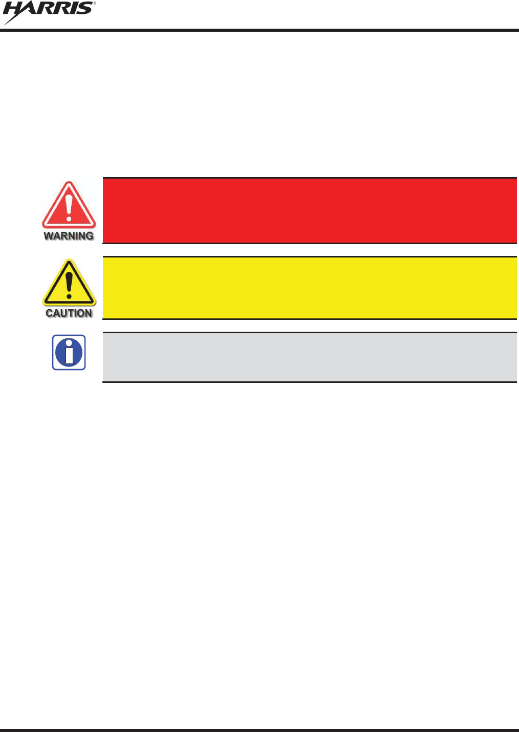
MM-012125-001, Rev. M
9
1. REGULATORY AND SAFETY INFORMATION
1.1 SAFETY SYMBOL CONVENTIONS
The following conventions are used in this manual to alert the user to general safety precautions that must
be observed during all phases of operation, installation, service, and repair of this product. Failure to
comply with these precautions or with specific warnings elsewhere violates safety standards of design,
manufacture, and intended use of the product. Harris assumes no liability for the customer's failure to
comply with these standards.
The WARNING symbol calls attention to a procedure, practice, or the like, which,
if not correctly performed or adhered to, could result in personal injury. Do not
proceed beyond a WARNING symbol until the conditions
identified are fully
understood or met.
The
CAUTION
symbol calls attention to an operating procedure, practice, or the like,
which, if not performed correctly or adhered to, could result in damage to the equipment
or severely degrade equipment perform
ance.
The
NOTE
symbol calls attention to supplemental information, which may improve
system performance or clarify a process or procedure.
NOTE
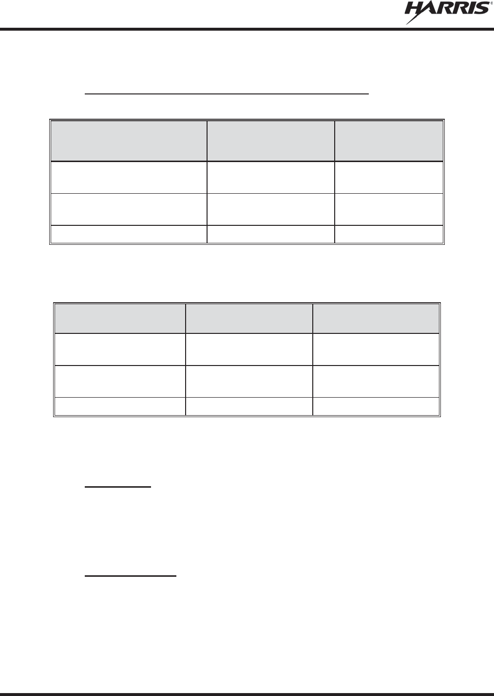
MM-012125-001, Rev. M
10
1.2 REGULATORY APPROVALS
1.2.1 Applicable Type Acceptance/Certification Numbers
Table 1-1: FCC Type Acceptance
RADIO
PART NUMBER FREQUENCY
RANGE/WATTAGE
FCC TYPE
ACCEPTANCE
NUMBER
RU
-144750-061 (
Rev. K or earlier)
764
-806 MHz, 30 Watt
806
-870 MHz, 35 Watt OWDTR-060-E
RU
-144750-
061 (Rev. L or later)
764
-806 MHz, 30 Watt
806
-870 MHz, 35 Watt OWDTR-0132-E
RU
-144750-181
900 MHz, 30 Watt
OWDTR-049-E
Applicable FCC Rules: Part 15, Part 80*, and Part 90
* FCC Part 80 is for 156-162 MHz only.
Table 1-2: Industry Canada Type Acceptance
RADIO
PART NUMBER FREQUENCY
RANGE/WATTAGE
IC TYPE ACCEPTANCE
NUMBER
RU
-144750-061
(Rev. K or earlier)
764
-806 MHz, 30 Watt
806-870 MHz, 35 Watt
3636B-0051
RU
-144750-061
(Rev. L or later)
764
-806 MHz, 30 Watt
806-870 MHz, 35 Watt
3636B-0132
RU-144750-181
900 MHz, 30 Watt
3636B-0049
Applicable Industry Canada Rules: RSS 119; RSS 210
1.3 RADIO FREQUENCY INTERFERENCE
1.3.1 FCC Part 15
This device complies with Part 15 of the FCC Rules. Operation is subject to the following two conditions:
1. This device may not cause harmful interference; and,
2. This device must accept any interference received, including interference that may cause undesired operation.
1.3.2 Industry Canada
This device complies with Industry Canada license-exempt RSS standard(s). Operation is subject to the
following two conditions: (1) this device may not cause interference, and (2) this device must accept any
interference, including interference that may cause undesired operation of the device.
Le présent appareil est conforme aux CNR d'Industrie Canada applicables aux appareils radio exempts de
licence. L'exploitation est autorisée aux deux conditions suivantes : (1) l'appareil ne doit pas produire de
MM-012125-001, Rev. M
11
brouillage, et (2) l'utilisateur de l'appareil doit accepter tout brouillage radioélectrique subi, même si le
brouillage est susceptible d'en compromettre le fonctionnement.
1.4 RF ENERGY EXPOSURE AWARENESS AND CONTROL
INFORMATION FOR FCC OCCUPATIONAL USE REQUIREMENTS
Before using the two-way mobile radio, review the following important RF energy awareness and
control information and operational instructions. Comply with this information and instructions to
ensure compliance with RF exposure guidelines.
This radio is intended for use in occupational/controlled conditions, where users
have full knowledge of their exposure and can exercise control over their exposure
to remain below RF exposure limits. This radio is NOT authorized for general
population, consumer, or any other use.
Changes or modifications not expressly approved by Harris could void the user's
autho
rity to operate the equipment.
This two-way radio uses electromagnetic energy in the radio frequency (RF) spectrum to provide
communications between two or more users over a distance. It uses RF energy or radio waves to send and
receive calls. RF energy is one form of electromagnetic energy. Other forms include, but are not limited
to, electric power, sunlight, and x-rays. RF energy, however, should not be confused with these other
forms of electromagnetic energy, which, when used improperly, can cause biological damage. Very high
levels of x-rays, for example, can damage tissues and genetic material.
Experts in science, engineering, medicine, health, and industry work with organizations to develop
standards for exposure to RF energy. These standards provide recommended levels of RF exposure for
both workers and the general public. These recommended RF exposure levels include substantial margins
of protection. All two-way radios marketed in North America are designed, manufactured, and tested to
ensure they meet government-established RF exposure levels. In addition, manufacturers also recommend
specific operating instructions to users of two-way radios. These instructions are important because they
inform users about RF energy exposure and provide simple procedures on how to control it. Refer to the
following websites for more information on what RF energy exposure is and how to control exposure to
assure compliance with established RF exposure limits:
http://www.fcc.gov/oet/rfsafety/rf-faqs.html
http://www.osha.gov./SLTC/radiofrequencyradiation/index.html
1.4.1 Federal Communications Commission Regulations
Before it was marketed in the United States, the M5300 series two-way mobile radios were tested to
ensure compliance with FCC RF energy exposure limits for two-way mobile radios. When two-way
radios are used as a consequence of employment, the FCC requires users to be fully aware of and able to
control their exposure to meet occupational requirements. Exposure awareness can be facilitated by the
use of a label directing users to specific user awareness information. The radio has an RF exposure
product label. Also, this Product Safety Manual and the applicable Operator’s Manual include
information and operating instructions required to control RF exposure and to satisfy compliance
requirements.
MM-012125-001, Rev. M
12
1.5 COMPLIANCE WITH RF EXPOSURE STANDARDS
The M5300 series two-way mobile radios are designed and tested to comply with a number of national
and international standards and guidelines regarding human exposure to RF electromagnetic energy. The
radios comply with the IEEE and ICNIRP exposure limits for occupational/controlled RF exposure
environment at duty-cycle times of up to 50% (50% transmit, 50% receive) and it is authorized by the
FCC for occupational use. In terms of measuring RF energy for compliance with the FCC exposure
guidelines, each radio’s antenna radiates measurable RF energy only while it is transmitting (talking), not
when it is receiving (listening), or in a standby mode.
The M5300 series two-way mobile radios comply with the following RF energy exposure standards and
guidelines:
x United States Federal Communications Commission (FCC), Code of Federal Regulations; 47
CFR § 2 sub-part J.
x American National Standards Institute (ANSI)/Institute of Electrical and Electronic Engineers (IEEE)
C95.1-2005.
x Institute of Electrical and Electronic Engineers (IEEE) C95.1-2005.
x IC Standard RSS-102, Issue 4, 2010: Spectrum Management and Telecommunications Radio
Standards Specification. Radiofrequency Exposure Compliance of Radiocommunication Apparatus
(All Frequency Bands).
Table 1-3 and Table 1-4 list the recommended minimum safe lateral distances for a
controlled environment and for unaware bystanders in an uncontrolled environment,
from transmitting antennas (i.e., monopoles over a ground plane, or dipoles) at rated
radio power for mobile radios installed in a vehicle. Transmit only when unaware
bystanders are at least the uncontrolled recommended minimum safe lateral distance
away from the transmitting antenna.
Based on the highest radiated RF power and the highest antenna gain in antennas used with M5300 series
radios, the distances listed in Table 1-3 and Table 1-4 are considered as safe distances for controlled and
uncontrolled environments with the M5300 series mobile radios transmitting at a maximum 50% duty
cycle:
1.5.1 Mobile Antennas
The antenna(s) for the radio must be installed in accordance with the antenna installation procedures
presented in the radio’s Installation Manual. Also refer to any special instructions included with the
antenna.
Use only approved/supplied antenna(s) or an approved replacement antenna. Unauthorized antennas,
modifications, or attachments can cause the FCC RF exposure limits to be exceeded.
1.5.2 Approved Accessories
The radio has been tested and meets FCC RF guidelines when used with accessories supplied or
designated for use with it. Use of other accessories may not ensure compliance with the FCC’s RF
exposure guidelines, and may violate FCC regulations. For a list of approved accessories, refer to the
radio’s Installation Manual and/or to the Products and Services Catalog.

MM-012125-001, Rev. M
13
1.5.3 Mobile Antennas (Vehicle Installations)
Table 1-3
: Rated Power and Recommended Minimum Safe Lateral Distance (Vehicle Installations)
MOBILE RADIO
FREQUENCY
SPLIT
ANTENNA
PART NUMBER
ANTENNA DESCRIPTION
RECOMMENDED MINIMUM LATERAL
HUMAN BODY DISTANCE FROM
TRANSMITTING ANTENNA
CONTROLLED
ENVIRONMENT
UNCONTROLLED
ENVIRONMENT
700/800 MHz
AN-125001-002 (mount)
with
AN-225001-001 (element)
700/800
MHz Standard
Rooftop
-Mount; 3
dBd Gain
9.8 Inches
(25 Centimeters)
21.7 Inches
(55 Centimeters)
700/800 MHz
AN-125001-002 (mount)
with
AN-225001-002 (element)
700/800 MHz Standard
Rooftop-Mount;
Elevated-Feed 3 dBd Gain
700/800 MHz
AN-125001-
002 (mount)
with
AN
-225001-
003 (element)
700/800 MHz Standard
Rooftop-
Mount; Elevated-
Feed, No Ground Plane
3 dBd Gain
700/800 MHz
AN-125001-002 (mount)
with
AN-225001-004 (element)
700/800 MHz Standard
Rooftop-Mount;
Low-Profile 2 dBd Gain
700/800 MHz
AN-125001-002 (mount)
with
AN-225001-005 (element)
700/800
MHz Standard
Rooftop
-Mount; 5
dBd Gain
11.8 Inches
(30 Centimeters)
23.6 Inches
(60 Centimeters)
700/800 MHz
AN-125001-004 (mount)
with
AN-225001-001 (element)
700/800 MHz Thick
Rooftop
-Mount; 3
dBd Gain
9.8 Inches
(25 Centimeters)
21.7 Inches
(55 Centimeters)
700/800 MHz
AN-125001-004 (mount)
with
AN-225001-002 (element)
700/800 MHz Thick
Rooftop-
Mount; Elevated-
Feed 3 dBd Gain
9.8 Inches
(25 Centimeters)
21.7 Inches
(55 Centimeters)
700/800 MHz
AN-125001-
004 (mount)
with
AN
-225001-
003 (element)
700/800 MHz Thick
Rooftop-
Mount; Elevated-
Feed, No Ground Plane
3 dBd Gain
700/800 MHz
AN-125001-004 (mount)
with
AN-225001-004 (element)
700/800 MHz Thick
Rooftop
-Mount; Low-
Profile
2 dBd Gain
700/800 M
Hz
AN-125001-004 (mount)
with
AN-225001-005 (element)
700/800 MHz Thick
Rooftop
-Mount; 5
dBd Gain
11.8 Inches
(30 Centimeters)
23.6 Inches
(60 Centimeters)
700/800 MHz
AN-125001-006 (mount)
with
AN-225001-001 (element)
700/800 MHz GPS Combo
Rooftop-Mount; 3
dBd /
5.15 dBi Gain
9.8 Inches
(25 Centimeters)
21.7 Inches
(55 Centimeters)
700/800 MHz
AN-125001-006 (mount)
with
AN-225001-002 (element)
700/800 MHz GPS Combo
Rooftop-Mount;
Elevated-Feed 3 dBd Gain
700/800 MHz
AN-125001-
006 (mount)
with
AN
-225001-
003 (element)
700/800 MHz GPS Combo
Rooftop-
Mount; Elevated-
Feed, No Ground Plane
3 dBd Gain

MM-012125-001, Rev. M
14
Table 1-3
: Rated Power and Recommended Minimum Safe Lateral Distance (Vehicle Installations)
MOBILE RADIO
FREQUENCY
SPLIT
ANTENNA
PART NUMBER
ANTENNA DESCRIPTION
RECOMMENDED MINIMUM LATERAL
HUMAN BODY DISTANCE FROM
TRANSMITTING ANTENNA
CONTROLLED
ENVIRONMENT
UNCONTROLLED
ENVIRONMENT
700/800 MHz
AN-125001-006 (mount)
with
AN-225001-004 (element)
700/800 MHz GPS Combo
Rooftop
-Mount; Low-
Profile
2 dBd Gain
700/800 MHz
AN-125001-006 (mount)
with
AN-225001-005 (element)
700/800 MHz GPS Combo
Rooftop-Mount; 5
dBd /
7.15 dBi Gain
11.8 Inches
(30 Centimeters)
23.6 Inches
(60 Centimeters)
700/800 MHz
AN-125001-008 (mount)
with
AN-225001-001 (element)
700/800 MHz Magnetic
-
Mount; 3 dBd Gain
9.8 Inches
(25 Centimeters)
21.7 Inches
(55 Centimeters)
700/800 MHz
AN-125001-008 (mount)
with
AN-225001-002 (element)
700/800 MHz Magnetic-
Mount;
Elevated-Feed 3 dBd Gain
700/800 MHz
AN-125001-008 (mount)
with
AN-225001-003 (element)
700/800 MHz Magnetic-
Mount; Elevated-
Feed, No
Ground Plane 3 dBd Gain
700/800 MHz
AN-125001-008 (mount)
with
AN-225001-004 (element)
700/800 MHz Magnetic-
Mount;
Low-Profile 2 dBd Gain
700/800 MHz
AN-125001-008 (mount)
with
AN-225001-005 (element)
700/800 MHz Magnetic
-
Mount; 5 dBd Gain 11.8 Inches
(30 Centimeters)
23.6 Inches
(60 Centimeters)
700/800 MHz
STI-Co
CCAS-SB-700
760 - 820 MHz Concealed
Peal-and-
Stick Internal-
Mount; dBi Gain
7.9 Inches
(20 Centimeters)
19.7 Inches
(50 Centimeters)
900 MHz
AN-125001-002 (mount)
with AN-225005-
001
(element)
900 MHz Standard
Rooftop-Mount;
3 dBd Gain
20 inches
(51 centimeters)
44.5 inches
(113 centimeters)
900 MHz
AN-125001-002 (mount)
with
AN-225005-002 (element)
900 MHz Standard
Rooftop-Mount;
Elevated-Feed 3 dBd Gain
900 MHz AN-125001-
002 (mount)
with
AN
-225005-
003 (element)
900 MHz Standard
Rooftop-Mount;
Elevated
-
Feed No Ground-
Plane 3 dBd Gain
900 MHz
AN-125001-002 (mount)
with
AN-225005-004 (element)
900 MHz Standard
Rooftop-Mount;
Low-Profile 2 dBd Gain
900 MHz AN-125001-
002 (mount)
with
AN
-225006-
001 (element)
132 to 960 MHz,
¼-Wavelength*;
Standard Rooftop-
Mount;
0 dBd Gain; Field-Tuned
900 MHz
AN-125001-004 (mount)
with
AN-225005-001 (element)
900 MHz Thick
Rooftop-Mount;
3 dBd Gain
20 inches
(51 centimet
ers)
44.5 inches
(113 centimeters)

MM-012125-001, Rev. M
15
Table 1-3
: Rated Power and Recommended Minimum Safe Lateral Distance (Vehicle Installations)
MOBILE RADIO
FREQUENCY
SPLIT
ANTENNA
PART NUMBER
ANTENNA DESCRIPTION
RECOMMENDED MINIMUM LATERAL
HUMAN BODY DISTANCE FROM
TRANSMITTING ANTENNA
CONTROLLED
ENVIRONMENT
UNCONTROLLED
ENVIRONMENT
900 MHz
AN-125001-004 (mount)
with AN-225005-
002
(element)
900 MHz Thick
Rooftop-Mount;
Elevated-Feed 3 dBd Gain
900 MHz AN-125001-
004 (mount)
with
AN
-225005-
003 (element)
900 MHz Thick
Rooftop-Mount;
Elevated
-Feed No
Ground-
Plane 3 dBd Gain
900 MHz
AN-125001-004 (mount)
with
AN-225005-004 (element)
900 MHz Thick
Rooftop-Mount;
Low-Profile 2 dBd Gain
900 MHz AN-125001-
004 (mount)
with AN-225006-
001
(element)
132 to 960 MHz,
¼-Wavelength*;
Thick Rooftop-Mount;
0 dBd Gain; Field-Tuned
900 MHz
AN-125001-006 (mount)
with
AN-225005-001 (element)
900 MHz GPS Combo
Rooftop-Mount;
3 dBd Gain
20 inches
(51 centimeters)
44.5 inches
(113 centimeters)
900 MHz
AN-125001-006 (mount)
with AN-225005-
002
(element)
900 MHz GPS Combo
Rooftop-Mount;
Elevated-Feed 3 dBd Gain
900 MHz AN-125001-
006 (mount)
with
AN
-225005-
003 (element)
900 MHz GPS Combo
Rooftop-Mount;
Elevated
-
Feed No Ground-
Plane 3 dBd Gain
9.8 Inches
(25 Centimeters)
21.7 Inches
(55 Centimeters)
900 MHz
AN-125001-006 (mount)
with
AN-225005-004 (element)
900 MHz GPS Combo
Rooftop-Mount;
Low-Profile 2 dBd Gain
900 MHz AN-125001-
006 (mount)
with AN-225006-
001
(element)
132 to 960 MHz,
¼-Wavelength*;
GPS Combo Rooftop
-
Mount;
0 dBd Gain; Field-Tuned
900 MHz
AN-125001-008 (mount)
with
AN-225005-001 (element)
900 MHz Magnetic-
Mount
3 dBd Gain
20 inches
(51 centimeters)
44.5 inches
(113 centimeters)
900 MHz
AN-125001-008 (mount)
with
AN-225005-002 (element)
900 MHz Magnetic-
Mount
Elevated-Feed 3
dBd Gain
900 MHz
AN-125001-008 (mount)
with
AN-225005-003 (element)
900 MHz Magnetic-Mount
Elevated
-
Feed No Ground-
Plane 3 dBd Gain
900 MHz
AN-125001-008 (mount)
with
AN-225005-004 (element)
900 MHz Magnetic-
Mount
Low-Profile 2
dBd Gain
900 MHz AN-125001-
008 (mount)
with
AN
-225006-
001 (element)
132 to 960 MHz,
¼-Wavelength*;
Magnetic-Mount;
0 dBd Gain; Field-Tuned
(Table Continued on Next Page)

MM-012125-001, Rev. M
16
Table 1-3
: Rated Power and Recommended Minimum Safe Lateral Distance (Vehicle Installations)
MOBILE RADIO
FREQUENCY
SPLIT
ANTENNA
PART NUMBER
ANTENNA DESCRIPTION
RECOMMENDED MINIMUM LATERAL
HUMAN BODY DISTANCE FROM
TRANSMITTING ANTENNA
CONTROLLED
ENVIRONMENT
UNCONTROLLED
ENVIRONMENT
900 MHz AN102800V1
(Discontinued)
136 – 941 MHz Standard
Rooftop-Mount; ¼-
Wave
Unity-Gain**
20 inches
(51 centimeters)
44.5 inches
(113 centimeters)
900 MHz Astron NMO9000
890 to 950 MHz NMO-Mount
Radome 3 dBi Gain
15.8 inches
(40 centimeters)
34.6 inches
(88 centimeters)
* Element must be trimmed to proper length to minimize antenna system VSWR.
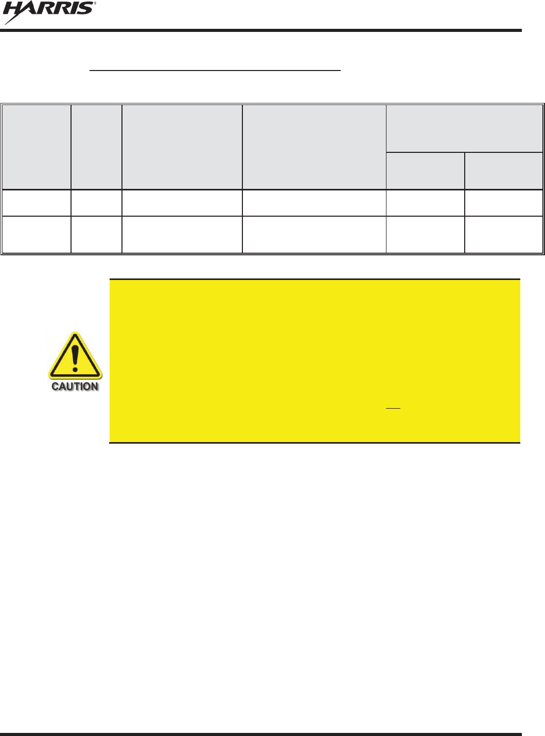
MM-012125-001, Rev. M
17
1.5.4 Mobile Antennas (Motorcycle Installations)
Table 1-4: Rated Power and Recommended Minimum Safe Lateral Distance (Motorcycle Installation)
RF
BAND
MAX. TX
POWER
(WATTS)
ANTENNA
PART NUMBER ANTENNA DESCRIPTION
RECOMMENDED MINIMUM
LATERAL HUMAN BODY
DISTANCE FROM TRANSMITTING
ANTENNA
CONTROLLED
ENVIRONMENT
(Centimeters)
UNCONTROLLED
ENVIRONMENT
(Centimeters)
800 MHz
20
LE
-
OM806HDBKTNCDS
800 MHz Motorcycle-Mount;
3.5 dBd Gain
28 72
700 or 800 MHz
20
AN-125001-006 (mount)
with
AN-225001-003 (element)
700/800 MHz GPS Combo; no-
Ground-Plane (NGP);
3 dBd / 5.15 dBi Gain
50 50
A radio used in a motorcycle installation must be configured with a transmit output
power level less than or equal to the
MAX. TX POWER (WATTS)
specification listed in
Table
1-4
for the respective frequency band and antenna/antenna element. Refer to the
radio’s
Installation Manual for additional information.
When a later
-
design motorcycle installation kit is employed (which uses antenna
element AN
-225001-003 or AN-225002-
004), the coaxial cable between the radio and
the base of the antenna mount cannot be shorter than 44
inches (111.8
centimeters).
Refer to the radio’s
Installation Manual for additional information.
A radio intended for a non
-motorcycle installation should not
be used in a motorcycle
installation unless it is reprogrammed per the procedures presented in the radio’s
Installation Manual
.
1.6 OCCUPATIONAL SAFETY GUIDELINES AND SAFETY TRAINING
INFORMATION
To ensure bodily exposure to RF electromagnetic energy is within the FCC allowable limits for
occupational use. Always adhere to the following basic guidelines:
x The push-to-talk button should only be depressed when intending to send a voice message.
x The radio should only be used for necessary work-related communications.
x The radio should only be used by authorized and trained personnel. It should never be operated by
children.
x Do not attempt any unauthorized modification to the radio. Changes or modifications to the radio may
cause harmful interference and/or cause it to exceed FCC RF exposure limits. Only qualified
personnel should service the radio.
x Always use only authorized accessories (antennas, control heads, speakers/mics, etc.). Use of
unauthorized accessories can cause the FCC RF exposure compliance requirements to be exceeded.
The information listed above provides the user with information needed to make him or her aware of a RF
exposure, and what to do to assure that this radio operates within the FCC exposure limits of this radio.

MM-012125-001, Rev. M
18
1.7 COMMON HAZARDS
The operator of any mobile radio should be aware of certain hazards common to
the operation of vehicular radio transmissions. Possible hazards include but are not
limited to:
x Explosive Atmospheres — Just as it is dangerous to fuel a vehicle while its engine is running, be
sure to turn the radio OFF while fueling the vehicle. If the radio is mounted in the trunk of the
vehicle, DO NOT carry containers of fuel in the trunk.
Areas with potentially explosive atmosphere are often, but not always, clearly marked. Turn the radio
OFF when in any area with a potentially explosive atmosphere. It is rare, but not impossible that the
radio or its accessories could generate sparks.
x Interference To Vehicular Electronic Systems — Electronic fuel injection systems, electronic anti-
skid braking systems, electronic cruise control systems, etc., are typical of the types of electronic
devices that can malfunction due to the lack of protection from radio frequency (RF) energy present
when transmitting. If the vehicle contains such equipment, consult the dealer for the make of vehicle
and enlist his aid in determining if such electronic circuits perform normally when the radio is
transmitting.
x Electric Blasting Caps — To prevent accidental detonation of electric blasting caps, DO NOT use
two-way radios within 1000 feet (305 meters) of blasting operations. Always obey the “Turn Off
Two-Way Radios” (or equivalent) signs posted where electric blasting caps are being used. (OSHA
Standard: 1926.900).
x Radio Frequency Energy — To prevent burns or related physical injury from radio frequency
energy, do not operate the transmitter when anyone outside of the vehicle is within the minimum safe
distance from the antenna as specified in Table 1-3 and Table 1-4. Refer to Section 1.2 for additional
information.
x Vehicles Powered By Liquefied Petroleum (LP) Gas — Radio installation in vehicles powered by
liquefied petroleum gas, where the LP gas container is located in the trunk or other sealed-off space
within the interior of the vehicle, must conform to the National Fire Protection Association standard
NFPA 58. This requires:
¾ The space containing the radio equipment must be isolated by a seal from the space containing
the LP gas container and its fittings.
¾ Outside filling connections must be used for the LP gas container.
¾ The LP gas container space shall be vented to the outside of the vehicle.
x Vehicles Equipped with Airbags — For driver and passenger safety, avoid mounting the radio’s
control head (or any other component) above or near airbag deployment areas. In addition to driver-
side and passenger-side front-impact airbags, some vehicles may also be equipped with side-impact
airbags. For occupant safety, verify the location of all airbags within the vehicle before installing the
radio equipment.
MM-012125-001, Rev. M
19
1.8 SAFE DRIVING RECOMMENDATIONS
The American Automobile Association (AAA) advocates the following key safe driving recommenda-
tions:
x Read the literature on the safe operation of the radio.
x Keep both hands on the steering wheel and the microphone in its hanger whenever the vehicle is in
motion.
x Place calls only when the vehicle is stopped.
x When talking from a moving vehicle is unavoidable, drive in the slower lane. Keep conversations
brief.
x If a conversation requires taking notes or complex thought, stop the vehicle in a safe place and
continue the call.
x Whenever using a mobile radio, exercise caution.
1.9 OPERATING RULES AND REGULATIONS
Two-way radio systems must be operated in accordance with the rules and regulations of the local,
regional, or national government.
In the United States, the M5300 mobile radio must be operated in accordance with the rules and
regulations of the Federal Communications Commission (FCC). Operators of two-way radio equipment
must be thoroughly familiar with the rules that apply to the particular type of radio operation. Following
these rules helps eliminate confusion, assures the most efficient use of the existing radio channels, and
results in a smoothly functioning radio network.
Under U.S. law, operation of an unlicensed radio transmitter within the jurisdiction of
the United States may be punishable by a fine of up to $10,000, imprisonment for up to
two (2) years, or bot
h.
When using a two-way radio, remember these rules:
x It is a violation of FCC rules to interrupt any distress or emergency message. The radio operates in
much the same way as a telephone “party line.” Therefore, always listen to make sure the channel is
clear before transmitting. Emergency calls have priority over all other messages. If someone is
sending an emergency message – such as reporting a fire or asking for help in an accident, do not
transmit unless assistance can be offered.
x The use of profane or obscene language is prohibited by Federal law.
x It is against the law to send false call letters or false distress or emergency messages. The FCC
requires keeping conversations brief and confined to business. Use coded messages whenever
possible to save time.
x Using the radio to send personal messages (except in an emergency) is a violation of FCC rules. Send
only essential messages.
x It is against Federal law to repeat or otherwise make known anything overheard on the radio.
Conversations between others sharing the channel must be regarded as confidential.
MM-012125-001, Rev. M
20
x The FCC requires self-identification at certain specific times by means of call letters. Refer to the
rules that apply to the particular type of operation for the proper procedure.
x No changes or adjustments shall be made to the equipment except by an authorized or certified
electronics technician.
1.10 OPERATING TIPS
The following conditions tend to reduce the effective range of two-way radios and should be avoided
whenever possible:
x Operating the radio in areas of low terrain, or while under power lines or bridges.
x Obstructions such as mountains and buildings.
In areas where transmission or reception is poor, communication improvement may
sometimes be obtained by moving a few yards in another direction, or moving to a
higher elevation.
NOTE
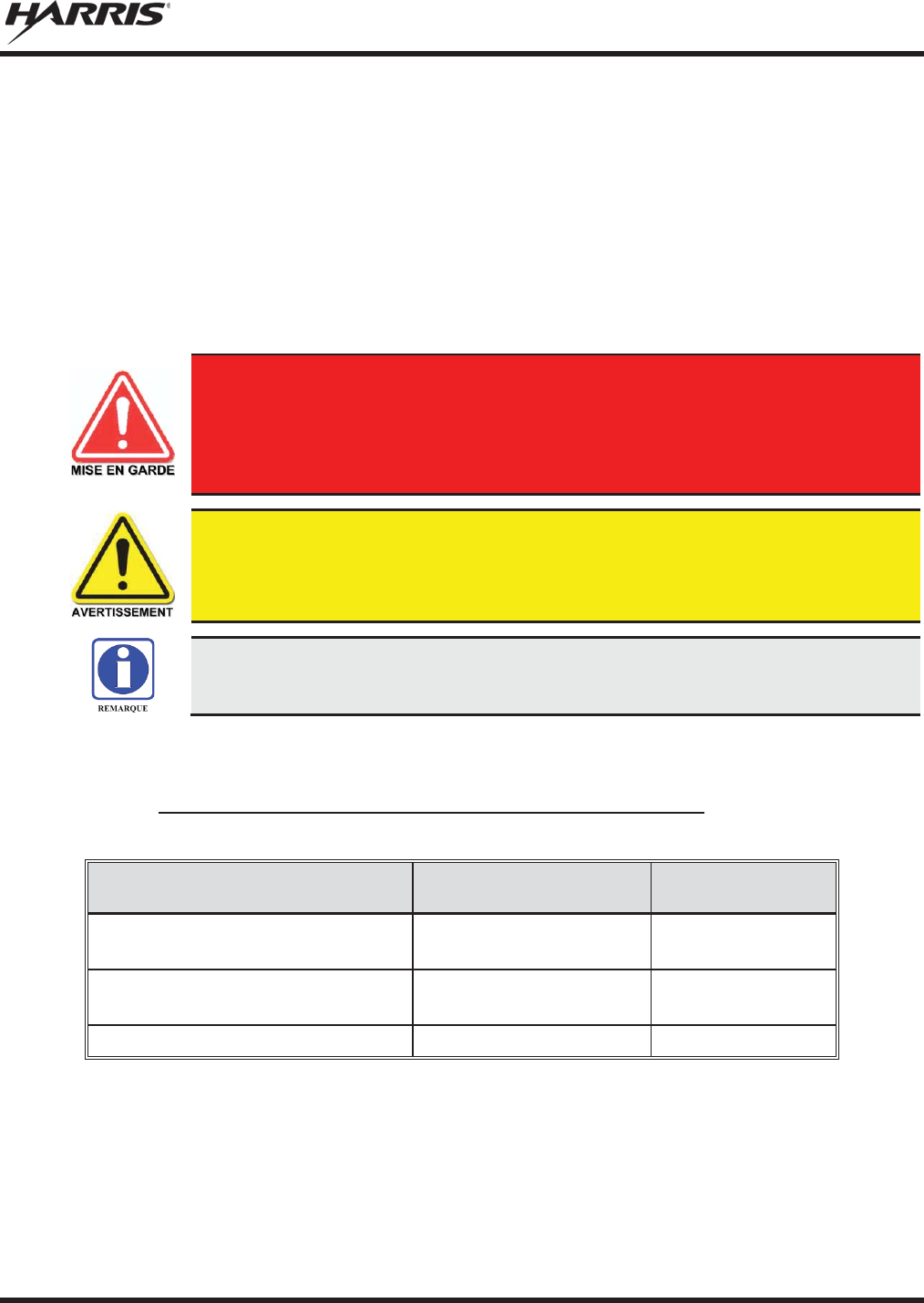
MM-012125-001, Rev. M
21
2. RENSEIGNEMENTS SUR LA RÉGLEMENTATION ET
SÉCURITÉ
2.1 CONVENTIONS SUR LES SYMBOLES DE SÉCURITÉ
Les conventions suivantes sont utilisées dans le présent manuel pour avertir l’utilisateur des précautions
générales de sécurité qui doivent être observées pendant toutes les phases d’opération, d’entretien et de
réparation de ce produit. Le non-respect de ces précautions ou d’avertissements précisés ailleurs enfreint
les normes de sécurité de la conception, de la fabrication et de l’utilisation prévue du produit. Harris
n’assume aucune responsabilité pour le non-respect de ces normes par le client.
Le symbole MISE EN GARDE attire l’attention sur une procédure ou une
pratique qui, si elle n’est pas correctement effectuée ou observée, pourrait
entraîner une blessure personnelle. Ne pas poursuivre au
-
delà d’un symbole de
MISE EN GARDE avant que les conditions identifiées soient complètement
comprises ou satisfaites.
Le symbole
AVERTISSEMENT attire l’attention sur une procédure ou une p
ratique
opérationnelle qui, si elle n’est pas correctement effectuée ou observée, pourrait
entraîner un bris d’équipement ou une importante baisse de rendement de l’équipement.
Le symbole
REMARQUE attire l’attention sur des renseignements supplémenta
ires qui
peuvent améliorer le rendement du système ou clarifier un processus ou une procédure.
2.2 CONFORMITÉ À LA RÉGLEMENTATION
2.2.1 Type Applicable Numéros Acceptation / Certification
Tableau 2-1: FCC Type de Acceptation
NUMÉRO DE PIÈCE
DE LA RADIO FRÉQUENCE
RADIO/WATTAGE
FCC TYPE NOMBRE
ACCEPTATION
RU
-144750-061 (Rev. K or earlier)
764
-806 MHz, 30 Watt
806
-870 MHz, 35 Watt OWDTR-060-E
RU
-144750-061 (Rev. L or later)
764
-806 MHz, 30 Watt
806
-870 MHz, 35 Watt OWDTR-0132-E
RU
-144750-181
900 MHz, 30 Watt
OWDTR-049-E
règles de la FCC applicables: Partie 15, Partie 80*, and Partie 90
* FCC Part 80 est à 156-162 MHz only.
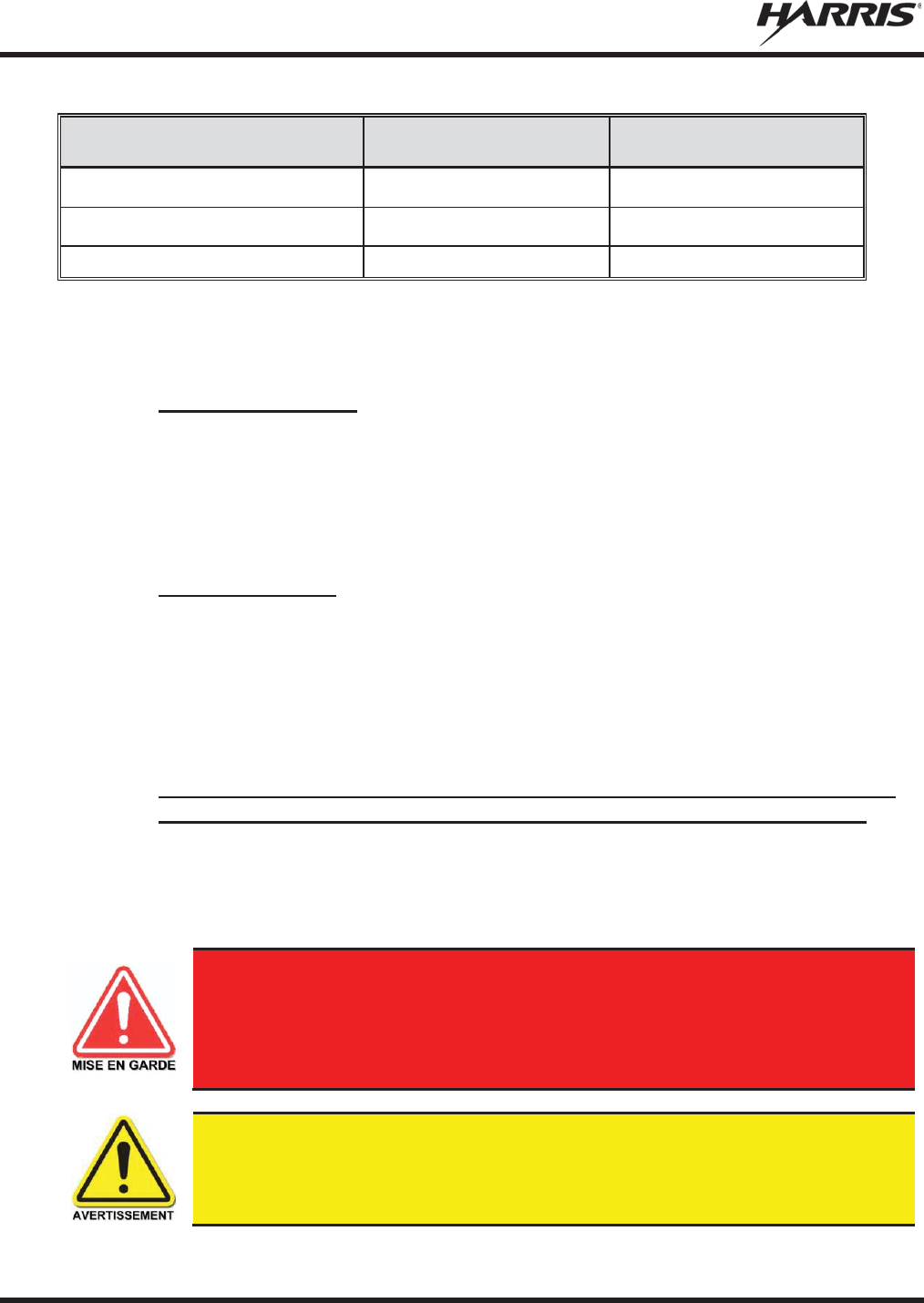
MM-012125-001, Rev. M
22
Tableau 2-2: Type de Canada Industrie Acceptation
NUMÉRO DE PIÈCE
DE LA RADIO FRÉQUENCE
RADIO/WATTAGE
CANADA INDUSTRIE TYPE
NOMBRE ACCEPTATION
RU
-144750-061 (Rev. K or earlier)
764-806 MHz, 30 Watt
806-870 MHz, 35 Watt
3636B-0051
RU
-144750-061 (Rev. L or later)
764-806 MHz, 30 Watt
806-870 MHz, 35 Watt
3636B-0132
RU
-144750-181
900 MHz, 30 Watt
3636B-0049
Reglement applicables d'Industrie Canada: RSS 119; RSS 210
2.3 INTERFÉRENCE DES RADIOFRÉQUENCES
2.3.1 Partie 15 de la FCC
Cet appareil est conforme à la Partie 15 de la réglementation de la FCC. Le fonctionnement est soumis
aux deux conditions suivantes :
1. Cet appareil ne doit pas causer une interférence nuisible; et
2. Cet appareil doit accepter toute interférence reçue, y compris une interférence qui peut causer un
fonctionnement non souhaité.
2.3.2 Industrie Canada
Cet appareil est conforme aux normes RSS exemptées de licence d’Industrie Canada. Le fonctionnement
est soumis aux deux conditions suivantes : (1) cet appareil ne doit pas causer d’interférence et (2) cet
appareil doit accepter toute interférence, y compris une interférence qui peut causer un fonctionnement
non souhaité de l’appareil.
2.4 RENSEIGNEMENTS SUR UNE EXPOSITION À L’ÉNERGIE DES RF
2.4.1 Renseignements Sur Le Contrôle Et La Sensibilisation À L’énergie Des
RF Pour Les Exigences D’une Utilisation Professionnelle De La FCC
Avant d’utiliser les radios mobiles bidirectionnelles, passez en revue les renseignements et les
instructions opérationnelles importants suivants sur le contrôle et la sensibilisation à l’énergie des
RF. Se conformer à ces renseignements et instructions pour assurer la conformité aux directives
d’exposition aux RF.
Cette radio est destinée à être utilisée dans des conditions professionnelles/
contrôlées, où les utilisateurs ont une pleine connaissance de leur exposition et
peuvent exercer un
contrôle sur leur exposition pour rester sous les limites
d’exposition aux RF. Cette radio N’est PAS autorisée pour la population générale,
les consommateurs ou toute autre utilisation.
Des changements ou modifications non expressément approuvés par Harris pourraient
annuler le droit d’utilisation de l’équipement pour l’utilisateur.

MM-012125-001, Rev. M
23
Cette radio bidirectionnelle utilise une énergie électromagnétique dans le spectre des radiofréquences
(RF) pour permettre une communication à distance entre deux utilisateurs ou plus. Elle utilise l’énergie
des RF ou les ondes radio pour envoyer et recevoir des appels. L’énergie des RF est une forme d’énergie
électromagnétique. D’autres formes comprennent, entre autres, l’énergie électrique, la lumière du soleil et
les rayons X. Toutefois, l’énergie des RF ne doit pas être confondue avec ces autres formes d’énergie
électromagnétique qui, lorsque mal utilisées, peuvent causer des dommages biologiques. Par exemple, des
niveaux très élevés de rayons X peuvent endommager les tissus et le matériel génétique.
Des experts en science, en ingénierie, en médecine, en santé et de l’industrie travaillent avec des
organismes pour établir des normes pour l’exposition à l’énergie des RF. Ces normes procurent des
niveaux recommandés d’exposition aux RF autant aux travailleurs qu’au grand public. Ces niveaux
d’exposition aux RF recommandés comprennent d’importantes marges de protection. Toutes les radios
bidirectionnelles commercialisées en Amérique du Nord sont conçues, fabriquées et testées pour s’assurer
qu’elles satisfont les niveaux d’exposition aux RF établis par le gouvernement. Les fabricants
recommandent également des consignes d’utilisation particulières aux utilisateurs de radios
bidirectionnelles. Ces instructions sont importantes, car elles informent les utilisateurs sur l’exposition à
l’énergie des RF et donnent des procédures simples sur la manière de contrôler cette exposition.
Consultez les sites Web suivants (en anglais) pour de plus amples renseignements sur ce qu’est
l’exposition à l’énergie des RF et comment contrôler l’exposition pour assurer la conformité aux limites
d’exposition établies :
http://www.fcc.gov/oet/rfsafety/rf-faqs.html
http://www.osha.gov./SLTC/radiofrequencyradiation/index.html
2.4.1.1 Règlements de la Federal Communications Commission (« Commission fédérale des
communications » aux États-Unis)
Avant d’être mise sur le marché aux États-Unis, la radio mobile bidirectionnelle M5300 a été testée pour
s’assurer de sa conformité aux limites d’exposition à l’énergie des RF de la FCC pour les radios mobiles
bidirectionnelles. Lorsque les radios bidirectionnelles sont utilisées à la suite d’une embauche, la FCC
demande aux utilisateurs de bien connaître et de pouvoir contrôler leur exposition pour satisfaire les
exigences professionnelles. La sensibilisation à l’exposition peut être facilitée par l’utilisation d’une
étiquette qui dirige les utilisateurs vers des renseignements particuliers sur la sensibilisation de
l’utilisateur. La radio possède une étiquette de produit sur l’exposition aux RF. De plus, le Manuel sur la
sécurité du produit et le présent Manuel de l’opérateur comprennent des renseignements et les consignes
d’utilisation nécessaires pour contrôler l’exposition aux RF et pour satisfaire les exigences de conformité.
2.5 CONFORMITÉ AUX NORMES D’EXPOSITION AUX RF
La radio mobile bidirectionnelle M5300 est conçue et testée pour être conforme à un certain nombre de
normes et directives nationales et internationales quant à l’exposition humaine à l’énergie
électromagnétique des RF. Cette radio est conforme aux limites d’exposition de l’IEEE et de la
Commission internationale de protection contre les rayonnements non ionisants pour un environnement
professionnel/contrôlé d’exposition aux RF à des périodes de cycle de service allant jusqu’à 50 % (50 %
de transmission, 50 % de réception) et elle est autorisée par la FCC pour une utilisation professionnelle.
Sur le plan de la mesure de l’énergie des RF pour la conformité aux directives d’exposition de la FCC,
l’antenne de la radio irradie une énergie des RF mesurable seulement lorsqu’elle transmet (parler), et non
lorsqu’elle reçoit (écouter) ou en mode d’attente.
La radio mobile bidirectionnelle M5300 est conforme aux normes et directives d’exposition à l’énergie
des RF suivantes :
x Federal Communications Commission (FCC) américaine, le Code of Federal Regulations; 47 CFR
§ 2 sous-partie J.
MM-012125-001, Rev. M
24
x American National Standards Institute (ANSI)/Institute of Electrical and Electronic Engineers (IEEE)
C95.1-2005.
x Institute of Electrical and Electronic Engineers (IEEE) C95.1-2005.
x IC Standard RSS-102, numéro 4, 2010 : Spectrum Management and Telecommunications Radio
Standards Specification. Radiofrequency Exposure Compliance of Radiocommunication Apparatus
(All Frequency Bands).
Tableau 2-3 par Tableau 2-4 indiquent les distances latérales sécuritaires minimales
recommandées pour un environnement contrôlé et pour les spectateurs ignorants dans
un environnement non contrôlé, d
’antennes de transmission (c.-à-
d., des monopôles sur
un plan de sol, ou des dipôles) à une puissance de radio évaluée pour les radios mobiles
installées dans un véhicule. Ils ne transmettent que lorsque les spectateurs ignorants
sont au moins à la distance latérale sécuritaire minimale recommandée non contrôlée
de l
’antenne de transmission.
Basées sur la puissance des RF irradiées la plus élevée et le gain d’antenne le plus élevé dans les antennes
à utiliser avec le M5300, les distances indiquées dans les Tableau 2-4 (pour une radio de motocyclette),
(pour la M5300 700/800 MHz), et (pour la M5300, 900 MHz) sont considérées comme des distances
sécuritaires pour des environnements contrôlés et non contrôlés avec la radio mobile M5300 qui transmet
à un cycle de service maximal de 50 %.
2.5.1 Antennes mobiles
Les antennes pour la radio doivent être installées conformément aux procédures présentées dans le
Manuel sur la sécurité du produit et dans le Manuel d’installation. L’installation est limitée à un ou des
véhicules motorisés en métal avec des plans au sol appropriés.
Utilisez uniquement les antennes approuvées/fournies ou une antenne de remplacement approuvée. Des
antennes, des modifications ou des accessoires non autorisés peuvent causer un dépassement des limites
d’exposition aux RF de la FCC.
2.5.2 Accessoires approuvés
La radio a été testée et satisfait les directives de RF de la FCC lorsqu’elle est utilisée avec les accessoires
fournis ou conçus pour être utilisés avec elle. L’utilisation d’autres accessoires peut ne pas garantir la
conformité aux directives d’exposition de la FCC et peut enfreindre la réglementation de la FCC. Pour
une liste d’accessoires approuvés, consultez le Manuel d’installation ou le Catalogue de produits et
services de Harris.
Utilisez toujours des accessoires autorisés Harris (antennes, haut
-
parleurs/micros,
etc.). L’utilisation d’accessoires non autorisés peut entraîner un dépassement des
exigences de conformité pour une exposition aux RF professionnelle ou contrôlée
de la FCC.

MM-012125-001, Rev. M
25
2.5.3 Monté Antennes (véhicule)
Tableau 2-3 : Distance latérale sécuritaire minimale recommandée d’
une antenne de transmission
branchée sur une radio mobile
RF
BAND
NUMÉRO DE PIÈCE DE
L’ÉLÉMENT DE
L’ANTENNE
DESCRIPTION DE
L’ANTENNE
DISTANCE MINIMALE RECOMMANDÉE DE
L
’
ANTENNE DE TRANSMISSION POUR LE
CORPS HUMAIN
ENVIRONNEMENT
CONTRÔLÉ
ENVIRONNEMENT NON
CONTRÔLÉ
700/800
MHz
AN
-125001-
002 (monture)
avec
AN
-225001-
001 (élément)
Antenne de toit standard de
700/800
MHz; gain de 3
dBd
25 cm
(9,8 po) 55 cm
(21,7 po)
700/800
MHz
AN
-125001-
002 (monture)
avec
AN
-225001-
002 (élément)
Antenne de toit
standard de
700/800 MHz; point
d’alimentation surélevé, gain
de 3 dBd
700/800
MHz
AN
-125001-
002 (monture)
avec
AN
-225001-
003 (élément)
Antenne de toit standard de
700/800 MHz; point
d’alimentation surélevé, gain
de 3
dBd sans plan de sol
700/800
MHz
AN
-125001-
002 (monture)
avec
AN
-225001-
004 (élément)
Antenne de toit standard de
700/800
MHz; gain de 2
dBd à
profil bas
700/800
MHz
AN
-125001-
002 (monture)
avec
AN
-225001-
005 (élément)
Antenne de toit standard de
700/800
MHz; gain de 5
dBd
30 cm
(11,8 po) 60 cm
(23,6 po)
700/800
MHz
AN
-125001-
004 (monture)
avec
AN
-225001-
001 (élément)
Antenne de toit épais de
700/800
MHz; gain de 3
dBd
25 cm
(9,8 po) 55 cm
(21,7 po)
700/800
MHz
AN
-125001-
004 (monture)
avec
AN
-225001-
002 (élément)
Antenne de toit
épais de
700/800 MHz; point
d’alimentation surélevé, gain
de 3 dBd
700/800
MHz
AN
-125001-
004 (monture)
avec
AN
-225001-
003 (élément)
Antenne de toit épais de
700/800 MHz; point
d’alimentation surélevé, gain
de 3
dBd sans plan de sol
700/800
MHz
AN
-125001-
004 (monture)
avec AN-225001-
004
(élément)
Antenne de toit épais de
700/800
MHz; gain de 2
dBd à
profil bas
700/800
MHz
AN
-125001-
004 (monture)
avec
AN
-225001-
005 (élément)
Antenne de toit épais de
700/800
MHz; gain de 5
dBd
30 cm
(11,8 po) 60 cm
(23,6 po)
700/800
MHz
AN
-125001-
006 (monture)
avec
AN
-225001-
001 (élément)
Combo antenne de toit et GPS
de 700/800
MHz; gain de
3 dBd / 5,15 dBi
25 cm
(9,8 po) 55 cm
(21,7 po)

MM-012125-001, Rev. M
26
Tableau 2-3 : Distance latérale sécuritaire minimale recommandée d’
une antenne de transmission
branchée sur une radio mobile
RF
BAND
NUMÉRO DE PIÈCE DE
L’ÉLÉMENT DE
L’ANTENNE
DESCRIPTION DE
L’ANTENNE
DISTANCE MINIMALE RECOMMANDÉE DE
L
’
ANTENNE DE TRANSMISSION POUR LE
CORPS HUMAIN
ENVIRONNEMENT
CONTRÔLÉ
ENVIRONNEMENT NON
CONTRÔLÉ
700/800
MHz
AN
-125001-
006 (monture)
avec
AN
-225001-
002 (élément)
Combo antenne de toit épais
et GPS de 700/800
MHz; point
d’alimentation surélevé, gain
de 3 dBd
25 cm
(9,8 po) 55 cm
(21,7 po)
700/800
MHz
AN
-125001-
006 (monture)
avec AN-225001-
003
(élément)
Combo antenne de toit et GPS
700/800 MHz; point
d’alimentation surélevé, gain
de 3
dBd sans plan de sol
700/800
MHz
AN
-125001-
006 (monture)
avec
AN
-225001-
004 (élément)
Combo antenne de toit et GPS
de 700/800
MHz; gain de
2 dBd à profil bas
700/800
MHz
AN
-125001-
006 (monture)
avec
AN
-225001-
005 (élément)
Combo antenne de
toit et GPS
de 700/800
MHz; gain de
5 dBd / 7,15 dBi
32 cm
(12,6 po) 72 cm
(28,3 po)
700/800
MHz
AN
-125001-
008 (monture)
avec AN-225001-
001
(élément)
Antenne magnétique de
700/800
MHz; gain de 3
dBd
25 cm
(9,8 po) 55 cm
(21,7 po)
700/800
MHz
AN
-125001-0
08 (monture)
avec
AN
-225001-
002 (élément)
Antenne magnétique de
700/800 MHz; point
d’alimentation surélevé, gain
de 3 dBd
700/800
MHz
AN
-125001-
008 (monture)
avec AN-225001-
003
(élément)
Antenne magnétique de
700/800 MHz; point
d’alimentation surélevé,
gain
de 3
dBd sans plan de sol
700/800
MHz
AN
-125001-
008 (monture)
avec
AN
-225001-
004 (élément)
Antenne magnétique de
700/800
MHz; gain de 2
dBd à
profil bas
700/800
MHz
AN
-125001-
008 (monture)
avec
AN
-225001-
005 (élément)
Antenne à monture
magnét
ique de 700/800
MHz;
gain de 5 dBd
30 cm
(11,8 po) 60 cm
(23,6 po)
700/800
MHz
AN102800V1
(n’est plus vendu)
136 à 941
MHz, ¼ -
longueur
d’onde*; antenne de toit toit
standard; gain de 0 dBd
25 cm
(9,8 po) 55 cm
(21,7 po)
900
MHz
AN-125001-002 (monture)
avec
AN-225005-001 (élément)
Antenne de toit standard de
900 MHz; gain de 3 dBd
51 cm
(20,1 po)
113 centimeters
(44,5 po)
900
MHz
AN-125001-002 (monture)
avec
AN-225005-002 (élément)
Antenne de toit standard de
900
MHz; point d’alimentation
surélevé, gain de 3 dBd
900
MHz
AN
-125001-002
(monture)
avec
AN
-225005-003
(élément)
Antenne de toit standard de
900
MHz; point d’alimentation
surélevé, gain de 3
dBd sans
plan de sol
51 cm
(20,1 po)
113 centimeters
(44,5 po)

MM-012125-001, Rev. M
27
Tableau 2-3 : Distance latérale sécuritaire minimale recommandée d’
une antenne de transmission
branchée sur une radio mobile
RF
BAND
NUMÉRO DE PIÈCE DE
L’ÉLÉMENT DE
L’ANTENNE
DESCRIPTION DE
L’ANTENNE
DISTANCE MINIMALE RECOMMANDÉE DE
L
’
ANTENNE DE TRANSMISSION POUR LE
CORPS HUMAIN
ENVIRONNEMENT
CONTRÔLÉ
ENVIRONNEMENT NON
CONTRÔLÉ
900
MHz
AN-125001-002 (monture)
avec
AN-225005-004 (élément)
Antenne de toit standard de
900 MHz; gain de 2
dBd à
profil bas
900
MHz
AN
-125001-002
(monture)
avec
AN
-225006-001
(élément)
132 à 960 MHz ; ¼ - longueur
d’onde; antenne de toit
standard;gain de 0
dBd;
syntonisé sur place
900
MHz
AN-125001-004 (monture)
avec
AN-225005-001 (élément)
Antenne de toit épais de
900 MHz; gain de 3 dBd
900
MHz
AN-125001-004 (monture)
avec
AN-225005-002 (element)
Antenne de toit épais de
900
MHz; point d’alimentation
surélevé, gain de 3 dBd
900
MHz
AN
-125001-004
(monture)
avec
AN
-225005-003
(élément)
Antenne de toit épais de
900
MHz; point d’alimentation
surélevé, gain de 3
dBd sans
plan de sol
900
MHz
AN-125001-004 (monture)
avec
AN-225005-004 (élément)
Antenne de toit épais de
900 MHz; gain de 2
dBd à
profil bas
900
MHz
AN-125001-004 (monture)
avec
AN-225006-001 (élément)
132 à 960 MHz, ¼ - longueur
d’onde; pour toit épais; gain de
0 dBd; syntonisé sur place
900
MHz
AN-125001-006 (monture)
avec
AN-225005-001 (élément)
Combo antenne de toit et GPS
de 900
MHz; gain de 3
dBd /
5,15 dBi
51 centimeters
(20,1 po)
113 centimeters
(44,5 po)
900
MHz
AN
-125001-006
(monture)
avec
AN
-225005-002
(élément)
Combo antenne de toit épais
et GPS de 900
MHz; point
d’alimentation surélevé, gain
de 3 dBd
900
MHz
AN
-125001-006
(monture)
avec
AN
-225005-003
(élément)
Combo antenne de toit et GPS
900
MHz; point d’alimentation
surélevé, gain de 3
dBd sans
plan de sol
900
MHz
AN-125001-006 (mount)
with
AN-225005-004 (élément)
Combo antenne de toit et GPS
de 700/800
MHz; gain de
2 dBd à profil bas
900
MHz
AN
-125001-006
(monture)
avec
AN
-225006-001
(élément)
132 à 960 MHz, ¼ - longueur
d’onde; support sur le toit à
combo; gain de 0
dBd; champ
syntonisé
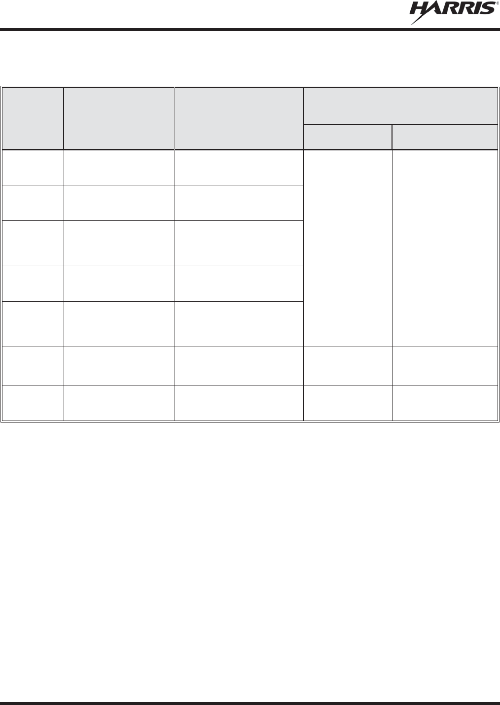
MM-012125-001, Rev. M
28
Tableau 2-3 : Distance latérale sécuritaire minimale recommandée d’
une antenne de transmission
branchée sur une radio mobile
RF
BAND
NUMÉRO DE PIÈCE DE
L’ÉLÉMENT DE
L’ANTENNE
DESCRIPTION DE
L’ANTENNE
DISTANCE MINIMALE RECOMMANDÉE DE
L
’
ANTENNE DE TRANSMISSION POUR LE
CORPS HUMAIN
ENVIRONNEMENT
CONTRÔLÉ
ENVIRONNEMENT NON
CONTRÔLÉ
900
MHz
AN-125001-008 (monture)
avec
AN-225005-001 (element)
Antenne magnétique de
900 MHz; gain de 3 dBd
51 centimeters
(20,1 po)
113 centimeters
(44,5 po)
900
MHz
AN-125001-008 (monture)
avec
AN-225005-002 (élément)
Antenne magnétique de
900
MHz; point d’alimentation
surélevé, gain de 3 dBd
900
MHz
AN
-125001-008
(monture)
avec
AN
-225005-003
(élément)
Antenne magnétique de
700/800 MHz; point
d’alimentation surélevé, gain
de 3 dBd sans plan de sol
900
MHz
AN-125001-008 (monture)
avec
AN-225005-004 (élément)
Antenne magnétique de
900 MHz; gain de 2
dBd à
profil bas
900
MHz
AN
-125001-008
(monture)
avec
AN
-225006-001
(élément)
132 à 960 MHz, ¼ - longueur
d’onde; antenne de toit à
monture magnétique; gain de
0 dBd; syntonisé sur plac
900
MHz
Astron NMO9000
890 to 950 MHz
NMO
-Mount Radome 3
dBi
Gain
40 centimeters
(15,8 po) 88 centimeters
(34,6 po)
900 MH
AN102800V1
(n’est plus vendu)
136 à 941 MHz, ¼ - longueur
d’onde*; antenne de toit toit
standard; gain de 0 dBd
25 cm
(9,8 po) 55 cm
(21,7 po)
* L'élément mené des pièces AN-225006-001 et AN102800V1 doit être ajusté à une longueur adéquate pour minimiser
le ROS du système d'antenne.
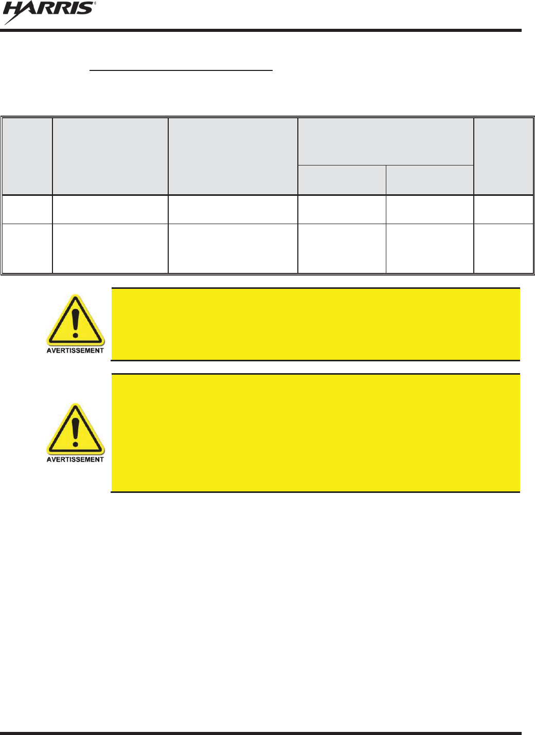
MM-012125-001, Rev. M
29
2.5.4 Monté Antennes (Motocyclette)
Tableau 2-4: Distance latérale sécuritaire minimale recommandée d’une antenne de transmission
branchée sur une radio Motocyclette
RF
BAND
NUMÉRO DE PIÈCE DE
L’ÉLÉMENT DE
L’ANTENNE
DESCRIPTION DE
L’ANTENNE
DISTANCE MINIMALE
RECOMMANDÉE DE L
’
ANTENNE DE
TRANSMISSION POUR LE CORPS
HUMAIN
MAX.
TX
PUISSANCE
(Watts)
ENVIRONNEMENT
CONTRÔLÉ
ENVIRONNEMENT
NON CONTRÔLÉ
800 MHz
LE
-
OM806HDBKTNCDS
800
MHz -
monture; gain de
3.5 dBd 28 cm 72 cm 20
700 or 800
MHz
AN
-125001-
006 (monture)
avec
AN
-225001-
003 (élément)
700/800 MHz; combo
antenne de toit et GPS; point
d’alimentation surélevé, gain
de 3 dBd sans plan de sol
50 cm 50 cm 20
Une radio utilisé dans une installation de motocyclette doit être configuré avec un
niveau de puissance
de sortie d'émission inférieur ou égal au maximum TX
Puissance
(Watts
) spécifications énumérées dans le Tableau 2-4 pour la bande de
fréquence
respective
et l'élément antenne / antenne. Reportez-vous au manuel d'installation
de la
radio
pour des informations supplémentaires.
Quand un kit d'installation de moto plus tard, la conception est employée (qui utilise
élément d'antenne
UN AN-225001-003 ou 225002-004), le câble coaxial
entre la radio
et
la base de la monture d'antenne ne peut pas être plus courte que 44 pouces (
111,8
cm)
. Reportez-vous au manuel d'installation de la radio
pour des informations
supplémentaires
.
Une radio
destinés à une installation non-moto ne doit pas être utilisé
dans une
installation
de moto sauf se il est reprogrammé par les procédures
présentées dans le
Manuel d'installation
de la radio.
2.6 RENSEIGNEMENTS SUR LA FORMATION SUR LA SANTÉ ET LA
SÉCURITÉ AU TRAVAIL
S’assurer que l’exposition physique à l’énergie électromagnétique des RF se situe dans les limites
acceptables de la FCC pour l’utilisation professionnelle. Toujours se conformer aux directives de base
suivantes:
x Le bouton de microphone doit être abaissé seulement lorsque l’on souhaite envoyer un message
vocal.
x La radio doit être utilisée seulement pour les communications nécessaires liées au travail.
x La radio doit être utilisée seulement par du personnel autorisé et formé. Elle ne doit jamais être
utilisée par des enfants.

MM-012125-001, Rev. M
30
x Ne tentez pas d’apporter une modification non autorisée à la radio. Des changements ou des
modifications à la radio peuvent causer une interférence nocive ou entraîner un dépassement des
limites d’exposition aux RF de la FCC. Seul le personnel qualifié doit utiliser la radio.
x Utilisez toujours seulement des accessoires autorisés (antennes, haut-parleurs/micros, etc.).
L’utilisation d’accessoires non autorisés peut entraîner un dépassement des exigences de conformité
pour une exposition aux RF de la FCC.
Les renseignements donnés ci-dessus donnent à l’utilisateur les renseignements nécessaires pour le
sensibiliser à l’exposition aux RF et sur ce qu’il faut faire pour s’assurer que cette radio fonctionne dans
les limites d’exposition de la FCC de cette radio.
2.7 DANGERS COURANTS
L'utilisateur de toute radio mobile doit être informé des dangers courants aux
transmissions par des radios de véhicules.
Les dangers éventuels
comprennent,
sans toutefois s'y limiter
:
x Atmosphères explosives – De la même manière qu'il est dangereux de faire le plein d'essence d'un
véhicule dont le moteur est en marche, s'assurer que la radio est éteinte (position OFF) avant de faire
le plein d'essence. NE PAS transporter de conteneurs de carburant dans le coffre d'un véhicule si la
radio est montée dans celui-ci.
Les zones avec une atmosphère potentiellement explosive sont souvent, mais pas toujours, clairement
signalés. Éteindre la radio (position OFF) dans toutes les zones avec une atmosphère potentiellement
explosive. Il est rare, mais pas impossible, que la radio ou ses accessoires génère des étincelles.
x Interférences avec les systèmes électroniques de véhicules – Les systèmes électroniques à injection
de carburant, les systèmes électroniques de freinage antidérapage, les systèmes électroniques de
régulateur de vitesse, etc., sont des systèmes pouvant mal fonctionner en raison d'une protection
insuffisante contre l'énergie RF présente lors des transmissions. Si le véhicule est équipe de tels
systèmes, consulter le concessionnaire pour obtenir des informations sur la marque du véhicule et
déterminer si de tels circuits électroniques fonctionnent normalement lorsque le radio émet.
x Détonateurs électroniques – Afin d'éviter toute explosion accidentelle des détonateurs électriques,
NE PAS UTILISER les radios émetteur-récepteur à moins de 305 mètres (1 000 pieds) d'une
opération de dynamitage. Respecter toujours les signes d’extinction des radios émetteur-récepteur
affichés dans les endroits où les détonateurs électriques sont utilisés. (norme OSHA : 1926.900)
x Énergie des fréquences radio – Pour prévenir toute brûlure ou toute blessure physique connexe
causée par l'énergie des fréquences radio, ne pas faire fonctionner l'émetteur lorsqu'une personne à
l'extérieur du véhicule est située en deçà de la distance minimale sécuritaire de l'antenne, comme
stipulé à la Section 2.5.
x Véhicules alimentés au gaz de pétrole liquéfié (GLP) – L'installation de radios mobiles dans des
véhicules alimentés au gaz de pétrole liquéfié avec un réservoir GLP dans le coffre ou dans tout autre
espace scellé à l'intérieur du véhicule doit être conforme à la norme NFPA 58 de la National Fire
Protection Association. Exigences :

MM-012125-001, Rev. M
31
¾ L'emplacement qui abrite la radio doit être isolé et scellé de l'emplacement contenant le réservoir
de GLP et ses raccords.
¾ Des raccords de remplissage extérieurs doivent être utilisés pour le réservoir de GLP.
¾ Le réservoir de GLP doit être pourvu d'une évacuation vers l'extérieur du véhicule
x Véhicules équipés de coussins gonflables – Pour la protection du conducteur et celle des passagers,
éviter d'installer les têtes de commandes de la radio (ou tout autre composant) au-dessus ou à
proximité des zones de déploiement de ces coussins gonflables. Outre les coussins gonflables avant
du conducteur et du passager, certains véhicules peuvent aussi être équipés de coussins gonflables
latéraux. Pour la sécurité des occupants, vérifier l'emplacement de tous les coussins gonflables dans le
véhicule avant d'installer équipement radio.
2.8 RECOMMANDATIONS POUR UNE CONDUITE SÉCURITAIRE
Recommandations principales de l'American Automobile Association (AAA) pour une conduite en toute
sécurité :
x Lire la documentation sur la sécurité d'utilisation de la radio.
x Garder les deux mains sur le volant et ranger le microphone dans son support durant la conduite du
véhicule.
x Effectuer un appel seulement lorsque le véhicule est à l'arrêt.
x Si un appel doit être effectué alors que le véhicule est en mouvement, conduire dans la voie la plus
lente. Les conversations doivent être brèves.
x Si une conversation nécessite la prise de notes ou exige une réflexion plus approfondie, arrêter le
véhicule dans un endroit sûr et poursuivre l'appel.
x Toujours utiliser une radio mobile avec prudence.
2.9 RÈGLES ET RÉGLEMENTATIONS D'UTILISATION
Les systèmes de radio émetteur-récepteur doivent être utilisés conformément aux règles et
réglementations du gouvernement local, régional ou national.
Aux États-Unis, la radio mobile M5300 doit être utilisée conformément aux règles et réglementations de
la Commission fédérale des communications (FCC). L'opérateur d'une radio émetteur-récepteur doit être
pleinement familiarisé avec les règles qui s'appliquent au fonctionnement d'une radio de ce type. Le
respect de ces règles aide à éliminer la confusion, garantit une utilisation hautement efficace des canaux
radio existants et assure le bon fonctionnement du réseau radio.
Rappels des règles à suivre lors de l'utilisation d'une radio émetteur-récepteur :
x L'interruption de messages de détresse ou d'urgence constitue une violation des règles de la FCC. Le
fonctionnement de la radio est similaire au fonctionnement d'un téléphone « connexion multipoint ».
Par conséquent, toujours écouter avant d'émettre afin de s'assurer que le canal est libre. Les appels
d'urgence sont prioritaires sur tous les autres messages. Si un message d'urgence est en cours de
transmission (pour signaler un incendie ou demander de l'aide à la suite d'un accident, par exemple),
ne pas émettre de messages sauf pour venir en aide.
x La loi fédérale interdit l'utilisation d'un langage obscène ou blasphématoire.
MM-012125-001, Rev. M
32
x La loi interdit l'envoi de faux indicatifs d'appel ou de faux messages de détresse ou d'urgence. La
FCC exige que vos conversations soient brèves et s'en tiennent au sujet de l'appel. Pour gagner du
temps, utiliser autant que possible des messages codés.
x L'utilisation de la radio pour l'envoi de messages personnels (sauf en cas d'urgence) constitue une
violation des règles de la FCC. Envoyer des messages essentiels uniquement.
x La loi fédérale interdit la répétition ou la diffusion de toute information entendue via les
communications radio. Les conversations entre les utilisateurs qui partagent un même canal doivent
être traitées comme des messages confidentiels.
x La FCC exige que les utilisateurs s'identifient à certains moments au moyen de leur indicatif d'appel.
Se référer aux règles qui s'appliquent au type particulier d'activités pour la bonne procédure à suivre.
x Aucune modification ou aucun ajustement ne doit être fait à l'équipement, sauf par un technicien
électronique autorisé et certifié.
En vertu de la loi des États
-
Unis, l'utilisation d'un émetteur radio sans licence sur le
territoire américain est punissable d'une amende d'un maximum de 10
000
$, d'un
emprisonnement de deux (2) ans au maximum, ou les deux.

MM-012125-001, Rev. M
33
3. PRODUCT DESCRIPTION
Designed to meet the critical demands of utility and public service users, the M5300 mobile provides the
latest in digital radio technology. The M5300 mobile supports multiple operating modes, including
OpenSky® digital trunked operation, Enhanced Digital Access Communications System (EDACS®) or
ProVoiceTM trunked modes, P25 digital trunked mode, P25 digital conventional mode, and analog
conventional mode.
ProVoice,
P25 Trunked, and P25 conventional operation
are not supported on 900 MHz
M5300
radios.
The M5300 uses Time Division Multiple Access (TDMA) technology in the OpenSky mode to allow
multiple users to share a single RF channel. In addition, a single RF channel can support simultaneous
digital voice and data communications.
The M5300 provides integrated voice and data services. Voice operation is provided using a microphone
and speaker included in the radio installation kit. For data transfers, the M5300 is constructed with an
industry-standard RS-232 interface serial port for connecting an optional laptop PC. The PC, not included
with the M5300, provides network connectivity through the standard serial (DCE-type) interface.
The optional Global Positioning System (GPS) receiver module can provide standard GPS formatted data
over the air for vehicle tracking systems.
Data Encryption Standard (DES) and the optional Advanced Encryption Standard (AES) are available for
maximum communications security.
The M5300 radio uses the CH-721 Control Head which is available in two models: System and Scan. The
display is designed to maximize readability and ease of use. The CH-721 utilizes a 3-line 12-character
alphanumeric display with large buttons, volume knob, and channel knob, providing a user-friendly
interface.
The CH-721 control head can be mounted with the radio (front mount) or it can be mounted and operated
remotely. For remote mount installations configured with a CH-721 control head, all normal radio
operations and interfaces can be handled via the control head connected to the radio unit via a 3-wire
Controller Area Network (CAN) cable. Two control heads may be attached to a radio. Each control head
provides a serial access point for data and any one (only one at a time) can be connected to a data device
such as a personal computer.
Where multiple control heads are connected or where a dash-mount radio is installed with an additional
remote control head, the following features are available from each position:
x Outgoing voice calls can be initiated. Either control head can initiate a call but only one can talk at a
time. The other connected control head hears both sides of the conversation.
x Incoming and outgoing audio can be heard. (Outgoing audio is not broadcast at the source position.)
x Independent audio control is available.
x Radio settings such as talk group, Scan Mode etc., can be controlled. (Any connected control head
can override the radio settings of another connected control head.)
x Comfort settings, such as volume and display brightness that are applicable to the individual control
head can be adjusted and cannot be overridden by another control head.
x An optional intercom function is available between control units. Audio is broadcast to ALL
connected control heads.
NOTE

MM-012125-001, Rev. M
34
4. CHANGE OPERATING MODE
4.1 CHANGE FROM OTP MODE
To change from OTP operating mode to EDACS, P25, Conventional (ECP/XGP):
1. Use , CLR, or OPT to cycle through the menu until the “Mode Menu” appears in the bottom
line of the display.
2. Use to choose an available mode. Press MENU and confirm (Y/N) with and press
MENU again.
3. Press the MENU button to confirm.
Or
Preset button C can be configured via programming to reboot the radio into a particular application mode.
Or
Quick Button command 1# transitions the radio to ECP/XGP mode. If ECP/XGP mode is not loaded in
the radio, the radio displays “No App.”
4.2 CHANGE TO OTP MODE
1. Scroll through available systems until OpenSky is displayed.
2. After a few seconds, the radio transitions to OTP mode.
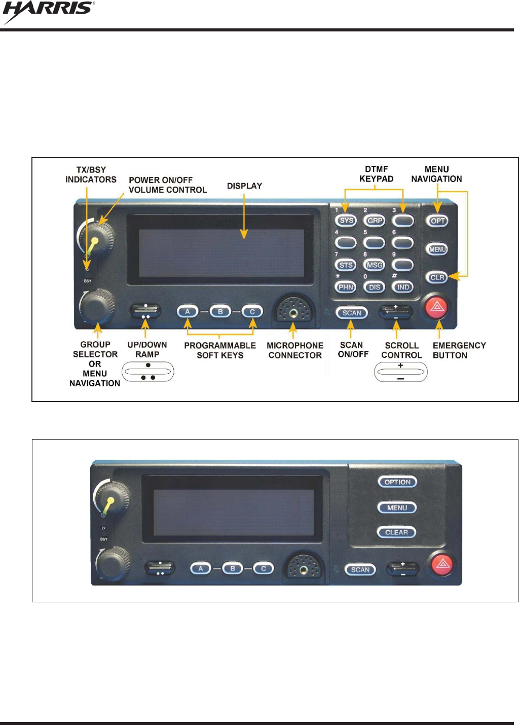
MM-012125-001, Rev. M
35
5. OPENSKY OPERATION
5.1 CH-721 FRONT PANEL COMPONENTS
The front panel of the control head includes a dot matrix display, controls for menu navigation, an
emergency button, three pre-set buttons, a power button/rotary volume dial, and a microphone connector.
In addition, the system model control head features a DTMF keypad. Table 5-1 lists all default front panel
controls and their functions.
Figure 5-1: System Model
Figure 5-2: Scan Model
The buttons on the front panel are backlit for operation in low ambient light. Some buttons also flash to
provide feedback of various operating conditions.
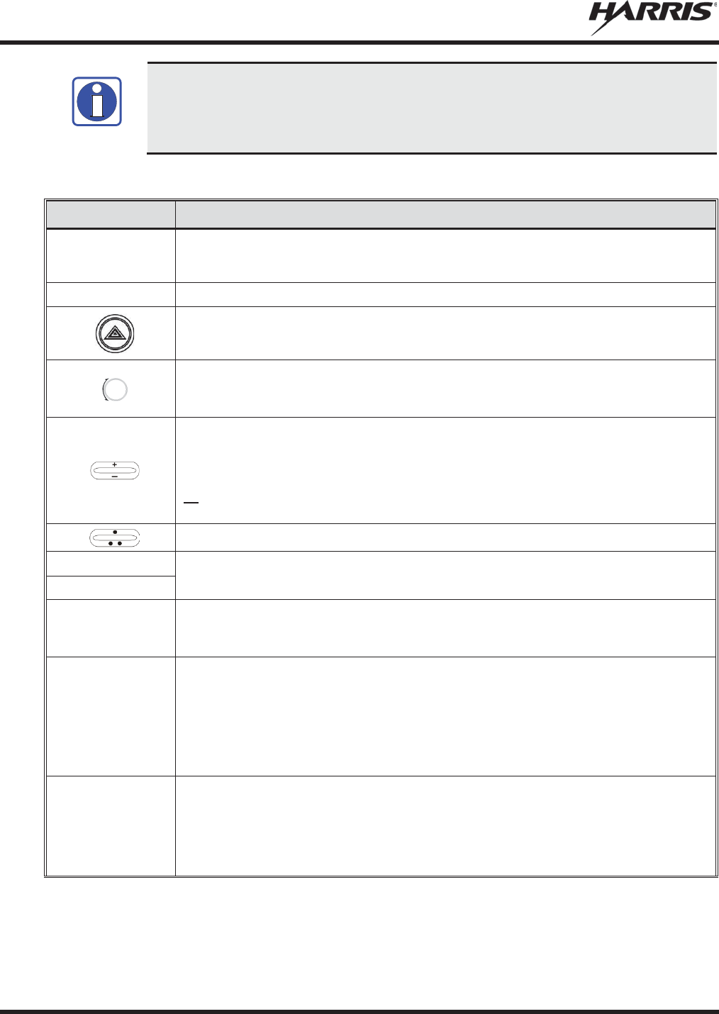
MM-012125-001, Rev. M
36
Button function may vary depending upon
radio programming. Any non-
DTMF button
can be configured to
various functions via the at**chkeymap command. Refer to t
he AT
command manual (MM
-016649-001) for all possible events. Table 5-1
describes the
default configuration.
Table 5-1: Front Panel Default Controls and Functions
PART
FUNCTION
Power On
-
Off/Volume Control
K
nob
Turn knob clockwise to power on the radi
o and increase volume.
Turn counter
-clockwise to decrease volume and power off the radio.
Mic
Connection
Connection for hand
-held, hands-free, speaker-mic, headset, or programming cable.
If enabled through programming, the emergency button sends an emergency and opens
voice communication on the currently selected talk group or the default emergency talk group
(depending upon how the system is defined).
While in the dwell display, scrolls through available talk groups.
Scrolls through selections withi
n the active menu (available talk groups, pre-
programmed
speed dial numbers, canned alert messages, etc.).
IF ENABLED VIA PROGRAMMING
, w
hile in the dwell display, scrolls through available talk
group
.
Scrolls through selections within the active menu (a
vailable talk groups, pre-
programmed
speed dial numbers, canned alert messages, etc.).
Or
Increases and decreases the display brightness.
IF ENABLED VIA PROGRAMMING
, scrolls through available menu items.
OPT/OPTION
Scrolls through available menu item
s.
CLR/CLEAR
MENU
Press to activate the current selection. In some cases, this is not necessary as the last
selection automatically activate
s after a short period.
Also exits Stealth Mode.
Display Area
Menu selections and messages.
Network Connectivit
y icon.
RSSI Indicator.
Current Volume Level icon.
Volume represented numerically within the display (0 = Muted, 40 = Loudest).
User may select which one of several dwell displays the radio uses.
Pre-
Set Buttons
A, B, & C
These buttons are used to store and recall user-selectable parameters such as Scan Mode,
selected profile, selected talk group, and priority talk group. Different parameters can be
stored at each of the three different pre
-set buttons.
Preset button C can be configured via programming to reboot the radio into a particular
application mode. Contact your system administrator to determine if this feature is enabled in
your radio.
NOTE

MM-012125-001, Rev. M
37
PART
FUNCTION
SCAN
Toggles the Scan Mode ON/OFF.
x
If the Scan Mode is Normal and the Scan Mode is toggled Off, when the Scan Mo
de is
toggled On the Scan Mode is set to Normal.
x
If the Scan Mode is Fixed and the Scan Mode is toggled Off when the Scan Mode is
toggled On the Scan Mode is set to Fixed.
x
If the Scan Mode is Off when the radio boots up when the Scan Mode is toggled On the
Scan Mode is set to Normal.
5.2 POWER UP AND VOLUME CONTROL
5.2.1 Power Up
1. Rotate the Power On-Off/Volume Control knob clockwise to power on the radio. The display
illuminates when the radio powers up.
2. Wait for the power-up sequence to complete, which takes approximately ten (10) seconds.
During this time, if enabled for auto registration, the radio is provisioned with a customized user
personality designed for the user’s specific needs by the OpenSky network administrator.
If this personality contains encrypted talk groups or if the user is authorized for, and intends to use,
manual encryption, User Login must be performed. This requires a system model control head so that
the User ID and password can be entered.
3. When provisioning is complete, the radio displays the Dwell Display.
If User Login is required, the bottom line of the Dwell Display flashes the message “Pls Login.”
5.2.2 Volume Control
Turn the Power On-Off/Volume Control knob clockwise to increase the volume and counter-clockwise to
decrease the volume. The radio sounds a tone to indicate the current volume level.
5.3 SELF-TEST
After power-up, the M5300 radio undergoes a multi-function automatic registration procedure. As many
as sixteen (16) possible radio profiles are downloaded to the radio from the network in response to the
User’s ID.
5.4 LOGIN TO THE NETWORK
Login occurs either automatically (auto registration) if the radio has a valid registration or, if enabled and
authorized for encryption (Section 5.32), requires the user to enter a User ID and password.
If encryption is enabled and authorized on the radio, the user is prompted to “Pls Login” with the *1 login
command, a User ID, and password [System Model Control Head required].
1. Press *1 (Login command).
2. Enter the full 10-digit User ID.
3. Press the # key.
4. Enter the password.
MM-012125-001, Rev. M
38
x If the radio is configured for alpha-numeric passwords and the password has consecutive
duplicate numbers (“MES33” for example), enter # between the consecutive duplicate numbers
so the radio does not interpret the entry as a letter (“D” in this example).
x If the radio is configured for numeric-only passwords, do not enter # between duplicated
numbers.
5. Press the # key twice for alphanumeric passwords or once for numeric-only passwords.
The User ID may be remembered from the previous login. (Refer to Section 5.5 for further details
regarding log off commands.) The password is established before the radio is put into operation. Contact
the local OpenSky network administrator for more information.
If necessary, contact radio system administration personnel for login assistance and/or
radio
-specific login instructions.
5.5 LOG OFF THE NETWORK
The *0## command de-registers the radio. Typically, this is automatically performed when powering
down the radio. Using this method, the User ID is remembered by the radio so only the password is
needed at next login. Manually log off by pressing *0## (requires System Model control head).
5.6 TURN THE RADIO OFF
To turn the radio off, rotate the Power On-Off/Volume Control knob counter-clockwise. In multiple
control head installations, turning off the last powered-up control head also automatically turns off the
radio.
If enabled via programming, several user-selected radio settings (i.e., Scan Mode, pre-set buttons, and
side tone levels) are maintained for the next operational session. At the next radio power-up, maintained
settings automatically restore, along with the network personality settings. In multiple control head
installations, settings are maintained for each control head position.
If power is abruptly disconnected from the radio prior to executing the correct turn-off
procedure, user
-selected radio settings and last-
tuned channel information are lost. This
can extend the time required for the radio to register with the network upon the
subsequent power
-up.
5.7 MENU DISPLAY AND CONTROL AREA
Following power-up, the radio display shows the default talk group (Figure 5-3). , OPT/OPTION,
or CLR/CLEAR changes the display to the next available menu. In many cases, the dwell display
automatically re-appears after no menu buttons are pressed for a short period of time (between 10 and 30
seconds). For some menus such as the GPS and User ID menus, this does not occur unless the menu
up/down buttons are pressed.
When the dwell display is active, it changes to reflect the current profile, received talk group/caller ID
(when available), or channel if the channel menu is enabled. The second line of dwell menu changes
when the user presses the MENU button.
The radio’s display is highly interactive. It responds in the top and bottom text lines as the user presses
the menu buttons to scroll through the menu loop and the entries for each menu.
NOTE
NOTE
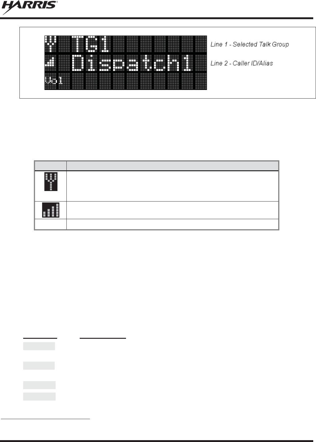
MM-012125-001, Rev. M
39
Figure 5-3: Typical Display
5.8 RADIO STATUS ICONS
Status Icons indicate the various operating characteristics of the radio. The icons show operating modes
and conditions (see Table 5-2). The location of icons on the display may vary depending on configuration.
Table 5-2: Icons and Descriptions
ICON
DESCRIPTION
Antenna
Indicates data registration.
Volume bars
– above VOL text indicates relative volume level.
RSSI bars appear to the right of the antenna icon.
5.9 DWELL DISPLAY
When not engaged in menu selection, the first two lines of the display default to the user-defined display,
known as the “dwell display.” The top line indicates the currently selected talk group. The second line
displays the currently selected profile, caller ID/alias1, received talk group, and current channel name.
Press the MENU button to scroll through and view one of these second line options.
5.10 ERROR MESSAGES
This section lists and describes the error messages that may be displayed by the M5300 during OpenSky
operation.
MESSAGE
DESCRIPTION
NOAUT01
Unspecified MDIS error. If condition persists in strong signal conditions, contact
your system administrator.
MDENIED
Unspecified MDIS error. If condition persists in strong signal conditions, contact
your system administrator.
UNAUTH3
Unauthorized IP. The radio network ID has not been added to network.
UNAUTH4
Bad authentication. If condition persists in strong signal conditions, contact your
system administrator.
1 Alias is a logical ID name such as “J_Smith.” The name corresponds to a user ID such as 003-542-0001.

MM-012125-001, Rev. M
40
MESSAGE
DESCRIPTION
UNAUTH5
Unsupported authentication. If condition persists in strong signal conditions, contact
your system administrator.
MDISBSY
The MDIS is busy. If condition persists in strong signal conditions, contact your
system administrator.
DUP IP
Duplicate IP.
BADIKEY
Invalid infrastructure public key sequence number (IPKSN).
BADEKEY
Invalid end-system public key sequence number (EPKSN).
UNK MES
Unknown mobile end system (MES). If condition persists in strong signal conditions,
contact your system administrator.
NOAUT05
MDIS failed mutual authentication. If condition persists in strong signal conditions,
contact your system administrator.
BADMDIS
MDIS failed mutual authentication. If condition persists in strong signal conditions,
contact your system administrator.
MDS BSY
MDIS busy – retry.
UNK DOM
Unknown home domain. If condition persists in strong signal conditions, contact
your system administrator.
KEYSYNC
Mismatched key sequence number.
UNK ALG
Unknown/unsupported encryption algorithm.
BADSIZE
Unsupported MDIS key size.
NOAUT11
MES failed data mutual authentication. If condition persists in strong signal
conditions, contact your system administrator.
NOAUT12
No response from MDIS. If condition persists in strong signal conditions, contact
your system administrator.
NOREPLY
No SME response from MDIS. If condition persists in strong signal conditions,
contact your system administrator.
VDENIED
Unspecified VNIC error.
If condition
persists in strong signal conditions, contact
your system administrator.
BAD VID
Invalid voice user ID. Check User ID. If correct, contact your system administrator.
HOM DWN
The Home VNIC is down. Retry. If error continues, contact your system
administrator.
SRV BSY
The serving VNIC is busy (congested).
MAX USR
The maximum number of users are already registered with the specified user ID.
OpenSky allows one User ID to log onto the network using up to three different
radios. Use *0## command or power do
wn one of the other radios to de-
register the
radio.
NAS BSY
The system cannot provision MES because of an administrative process.
NOAUTHM
The MES failed voice mutual authentication. If a valid radio displays this error,
contact TAC.

MM-012125-001, Rev. M
41
MESSAGE
DESCRIPTION
NOSUPRT
The MES ca
nnot support the required provision.
If condition persists in strong signal
conditions, contact your system administrator.
NOAUTHV
VNIC does not support or failed mutual authentication. If condition persists in strong
signal conditions, contact your system administrator.
PLS LOGIN
If enabled and auth
orized for encryption
, the radio requires the user to enter a User
ID and password. Login with keypad.
BAD PWD
Indicates an invalid password has been entered. Verify the password and re-enter.
OVER_TEMP
The
radio may be too hot. The radio ceases
transmitting if it exceeds an operational
temperature threshold. Let the radio cool before attempting to transmit. Report this
failure to an authorized technician.
No App
ECP/XGP mode is unavailable (not programmed).
NO PRIV
Missing required privilege.
NO SYNC
No forward
-
channel sync (weak or no coverage). If condition persists in strong signal
conditions, contact your system administrator.
No Access
Incoming encrypted voice cannot be decrypted. If condition persists in strong signal
conditions, contact your system administrator.
NO REG
Not registered with MDIS, VNIC, or both.
Locked Out
Another control head is actively using the user interface.
DISABLED
Function disabled (e.g., function invalid in current context).
5.11 PERSONALITY
As illustrated in Figure 5-4, a personality defines the profiles and talk groups available to the user. It is
the structuring of a collection of profiles and privileges established by the OpenSky network administrator
to provide the user with a comprehensive set of profiles to communicate effectively with the necessary
talk groups or individuals.
Personalities are stored on the network and downloaded over-the-air to the radio. This process is called
“provisioning.” Provisioning occurs at radio power-up and at user log-in. Each personality can contain up
to sixteen (16) profiles and each profile can contain up to sixteen talk groups.
5.11.1 Profiles
As stated above, each profile can contain up to sixteen (16) talk groups. A profile also defines the radio’s
emergency behavior. All transmissions are made on the selected talk group (displayed on the top line of
the dwell display). The user can change the selected talk group to any of the other talk groups within the
profile.
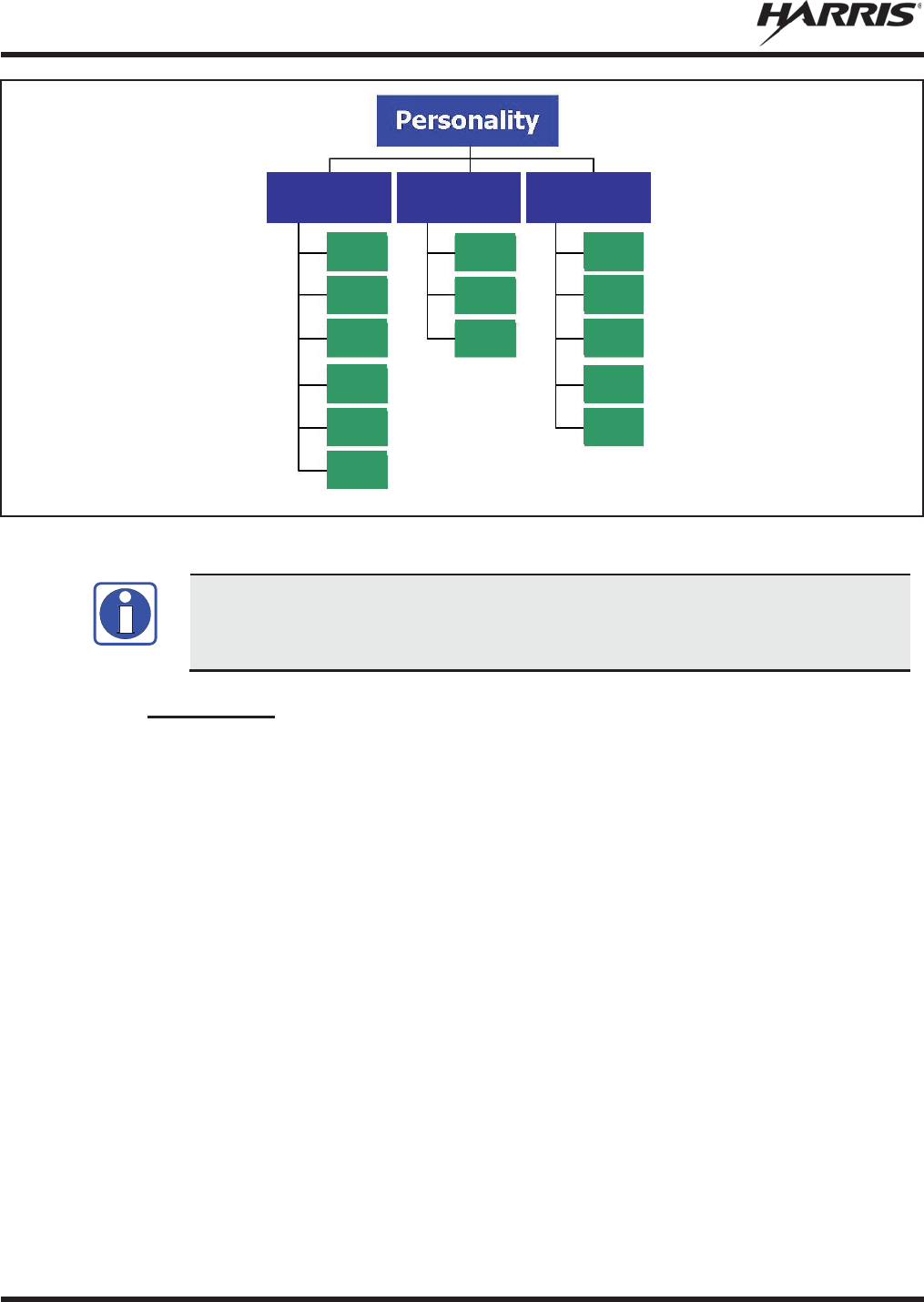
MM-012125-001, Rev. M
42
Figure 5-4: Personality Structure Example
If Global Profile is enabled by the system administrator, the number of available talk
groups to scan doubles.
5.11.2 Talk Groups
A talk group represents a set of users that regularly need to communicate with one another. There can be
any number of authorized users assigned to a talk group. Talk groups are established and organized by the
OpenSky network administrator. An OpenSky talk group is similar to a channel within a conventional FM
radio system.
TG a
TG b
TG c
TG x
TG y
TG z
TG d
TG e
TG f
TG a
TG d
TG g
TG h
TG i
TG = Talk Group
Profile 1
Profile 2
Profile 3
NOTE

MM-012125-001, Rev. M
43
5.12 ALERT TONES
The M5300 radio also provides audible Alert Tones or “beeps” to indicate the various operating
conditions (see Table 5-3).
Table 5-3: M5300 OpenSky Mode Alert Tones
NAME
TONE
DESCRIPTION
Call Queued
1 low tone/2 high tones
Call queued for processing.
Call Denied
3 short beeps
Radio is out of coverage area or requested talk group
is active.
Grant (or Go
-
Ahead)
1 short beep
Sounds when resources become available for a call
request placed in the queue (if enabled) upon channel
access.
If the radio roams to another site while transmitting,
then it auto rekeys and begins transmitting on that
tower. It gives a second grant tone to let the user
know they have roamed.
Priority Bump
1 short tone
Stopped current incoming call in favor of higher-
priority incoming call.
Call Removed
1 long low
-
pitched tone
Notifies the user access to the channel has been lost
(out of co
verage area or pre-empted by higher-
priority
call).
Selective Alert
Received
1 short tone, 2 short
beeps, 1 short tone
Only played once to indicate a selective alert has
been received.
Emergency Tone
3 long tones
Sounds when an emergency is declared.
Emergency
Cleared
1 long low
-
pitched tone
Sounds when an emergency is cleared.
Volume
1 short tone
Reflects current volume level.
Selective Call Ring
A
ringing tone similar to a
telephone
Ringing is repeated every four seconds until the call is
accepted or rejected by the radio being called or until
the network drops the call if unanswered after one
minute.
PSTN Ring
1 medium
-
pitch repeating
tone
Two ring tone - one generated by the radio when
there is an incoming telephone call or an outgoing
telephone call attempt is waiting for the telephone
interconnect gateway equipment to dial the Public
Switched Telephone Network (PSTN). The second
ring tone sounds when the gateway equipment has
dialed the number.
Roam
2 short tones, 1 high
-
pitched and 1 low
-
pitched
Sounds when the radio transitions from one base
station site to another while transmitting voice.
Out of Range
Tri
-tone beep
If enabled via programming, sounds when the radio is
not within operational range with base station.
Priority Bump
Sin
gle medium mid-
pitched tone.
Sounds when the current received call is preempted
by a higher priority call.
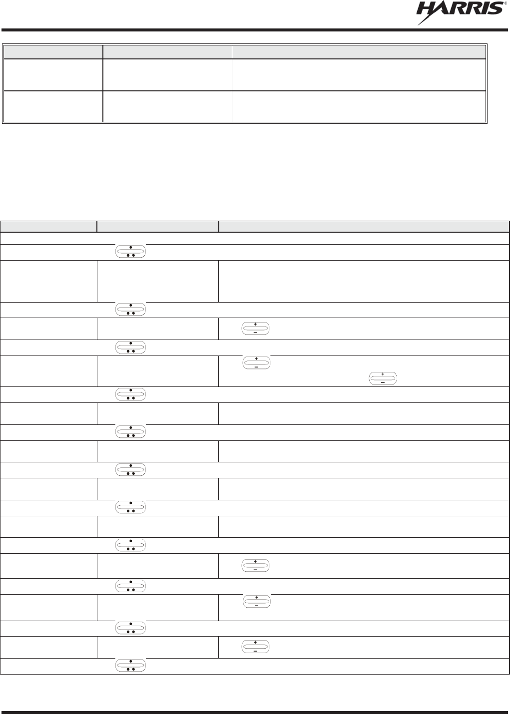
MM-012125-001, Rev. M
44
NAME
TONE
DESCRIPTION
Site Found Tone
Three short high
-
pitched
tones.
Sounds when the selected site is found using the Site
Lock Menu.
Site Not Found
Tone
Three short hi
gh-
pitched
tones.
Sounds when the selected site is not found using the
Site Lock Menu.
5.13 BASIC MENU STRUCTURE
Table 5-4 illustrates the basic M5300 OpenSky menu structure. Menu items vary depending upon system
programming, radio hardware, and optional configurations. All menus except the dwell display menu can
be turned off by network administration personnel.
Table 5-4: Basic Menu Structure
MENU NAME
RADIO DISPLAYS
USAGE NOTES
To/From Dwell Display
, CLR, or OPT
Engineering Display
bit-error rates,
RSSI data, sync status,
current channel and
registration status
Displays radio system connection data. For engineering use.
, CLR, or OPT
Silent Emergency
“SilentEmerg”
Use
to toggle Silent Emergency “On” or “Off.”
, CLR, or OPT
Operating Mode
“App Mode”
Use
to choose an available mode (OTP, ECP/XGP
, or OCF).
Press MENU and confirm (Y/N) with and press MENU again.
, CLR, or OPT
GPS Fix “GPS Fix”
Radio’s current GPS latitude and longitude position scrolls across top
line of the display. Applies to GPS-equipped radios only.
, CLR, or OPT
User ID “User ID”
User’s identification/name scrolls across top line of the display (if
programmed).
, CLR, or OPT
IP Address “IP Address”
Radio’s Internet Protocol (IP) address scrolls across top line of the
display.
, CLR, or OPT
Station Identification
“Station ID”
Station’s identification/name scrolls across top line of the display (if
programmed).
, CLR, or OPT
Stealth Mode “StealthMenu”
Use
to turn Stealth Mode “On.”
, CLR, or OPT
Treble Level “Treble Menu”
Use
to choose speaker/headset treble level (LOW, MEDIUM,
MEDHIGH, or HIGH). Press Select to return to dwell display.
, CLR, or OPT
Display Brightness
“Bright Menu”
Use
to dim or brighten. Press MENU
to return to dwell display.
, CLR, or OPT
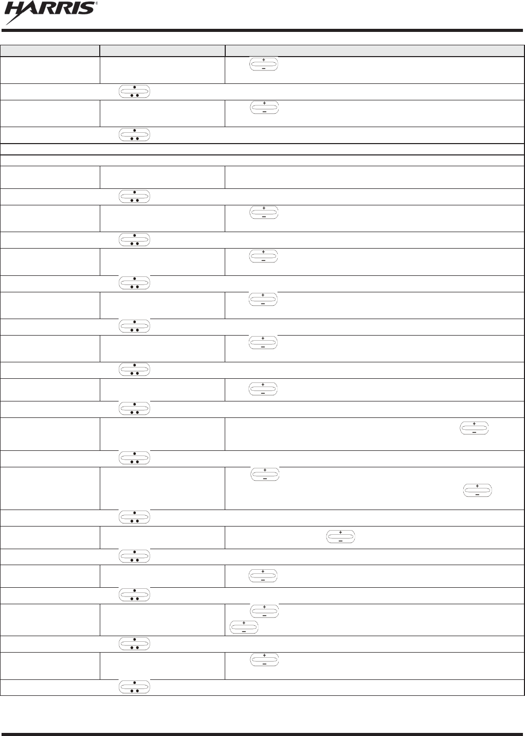
MM-012125-001, Rev. M
45
MENU NAME
RADIO DISPLAYS
USAGE NOTES
Side Tone Level
“Side Menu”
Use
to choose side tone level (Off, Low, Med, or High). Press
MENU to return to dwell display.
, CLR, or OPT
Intercom “INTERCOM”
Use
to turn intercom “On” or “Off.” Press MENU
to return to
dwell display.
, CLR, or OPT
See Next Page
See Previous Page
Selected Channel
“ChannelMenu”
Allows the user to display and change the current channel. Press
MENU to return to dwell display.
, CLR, or OPT
Scan Mode “ScnModeMenu”
Use
to select Scan Mode
(Normal, No Scan, or Fixed). Press
MENU to return to dwell display.
, CLR, or OPT
Talk group
Lock Out
“LockOutMenu”
Use
to choose a talk group for locking/unlocking. Press
MENU
to toggle “<” on (locked out) and off.
, CLR, or OPT
Priority 1
Talk group
“Priority1”
Use
to choose new priority talk group. Press MENU
to return to
dwell display.
, CLR, or OPT
Priority 2
Talk group
“Priority2”
Use
to choose new priority talk group. Press MENU
to return to
dwell display.
, CLR, or OPT
Emergency Dismiss
“EmgDismiss”
Use
to choose emergency talk group. Press MENU
to dismiss.
, CLR, or OPT
Alerts Received
“AlertsRcvd”
or oldest message
“No alerts” or alert message text scrolls in display. Use
to view
messages.
, CLR, or OPT
Alert Destination
“AlertDest”
Use
to choose a speed-dial number. Press MENU
to go to
“AlertMsg” menu. Scroll through canned messages with
.
Press
MENU to send message and return to dwell display.
, CLR, or OPT
Status LED “Status LED”
Press
MENU, then use
to turn the TX/RX LED “On” or “Off.”
, CLR, or OPT
Client Mode “Client Mode”
Use
to choose Client Mode (Network or SOI).
, CLR, or OPT
Speed Dial “SpeedDial”
Use
to choose a speed-dial number. Press MENU
, then use
to select canned message.
, CLR, or OPT
Profile Selection
“ProfileMenu”
Use
to choose an available profile. Press MENU
to return to
dwell display.
, CLR, or OPT
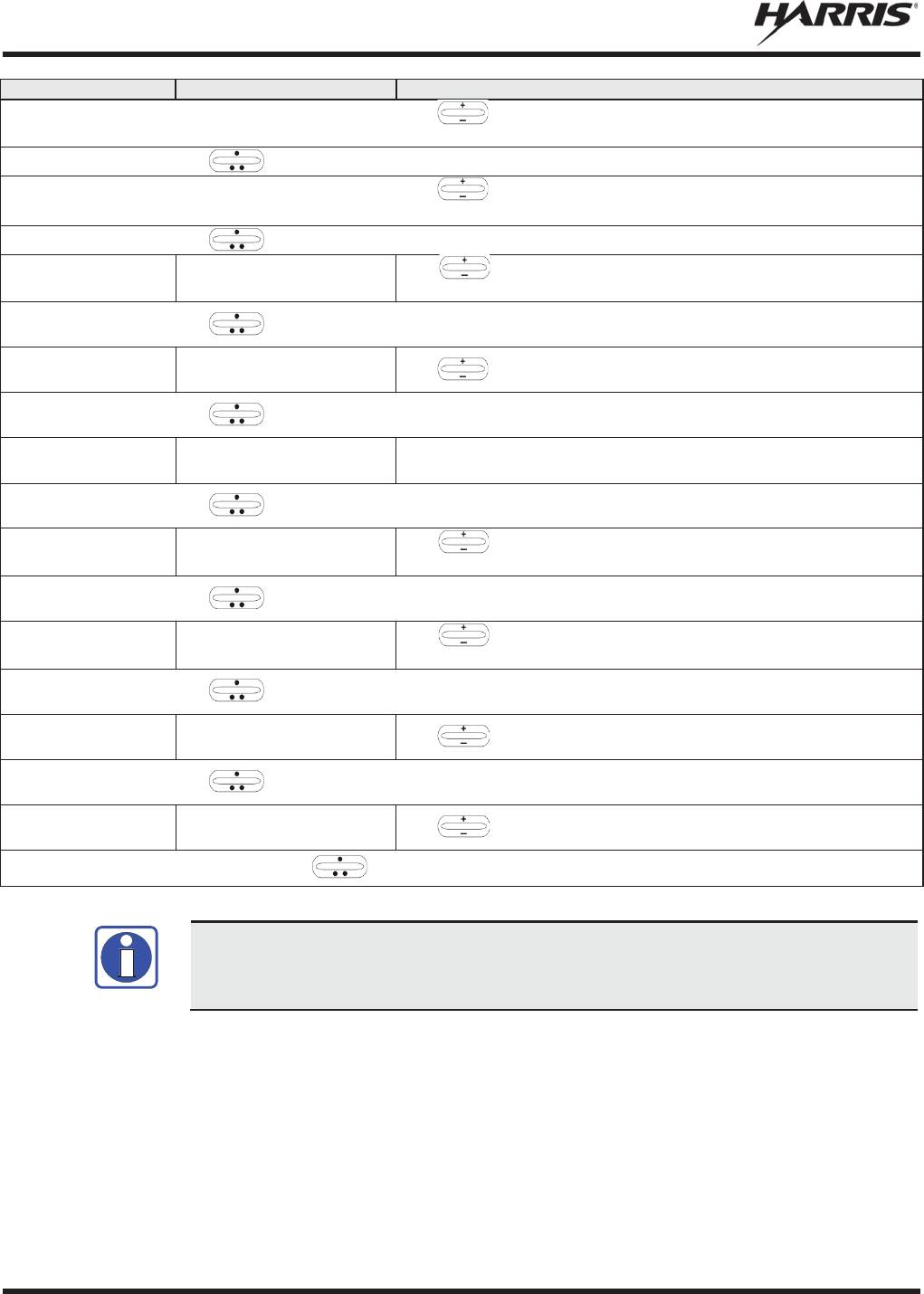
MM-012125-001, Rev. M
46
MENU NAME
RADIO DISPLAYS
USAGE NOTES
Request to Talk
Message
“RTT Msg”
Use
to scroll through available messages. Press MENU to
send the selected message.
, CLR, or OPT
Status Message
“Status Msg”
Use
to scroll through available messages. Press MENU
to send
the selected message.
, CLR, or OPT
Talk group Selection
“TalkGrpMenu”
Use
to choose a talk group in current profile. Press
MENU to
return to dwell display.
, CLR, or OPT
Site Lock “Site Lock”
Use
to scroll through sites. Press MENU to select site.
, CLR, or OPT
OTP Software Version
“Software Ver”
Displays OTP software version
Press MENU
to return to dwell display.
, CLR, or OPT
RF Diagnostics
“Diagnostics”
Use
to scroll through RF diagnostics displays. Press
MENU to
reset RF diagnostics counters.
, CLR, or OPT
Priority 3 Talk Group
“Priority 3”
Use
to choose Priority 3 talk group. Press MENU
to toggle “<”
on (selected) and off.
, CLR, or OPT
Public Address
“PA”
Use
to scroll to turn Public Address ON and OFF.
, CLR, or OPT
External Speaker
“SPKR SEL”
Use
to scroll to turn the External Speaker ON and OFF.
Use , CLR, or OPT to scroll through menus.
Menus vary depending upon system programming, radio hardware, and optional
configurations.
5.14 DUAL-TONE MULTI-FREQUENCY
Dual-Tone Multi-Frequency (DTMF) is the system used by touch-tone telephones. DTMF assigns a
specific tone frequency to each key so a microprocessor can easily identify its activation. The radio
supports DTMF with a system model control head (Figure 5-1). This allows for specific tasks such as
entering a user ID and password, or Selective Calling.
When a key on the DTMF keypad is pressed, the DTMF tone is played through the radio’s speaker.
NOTE
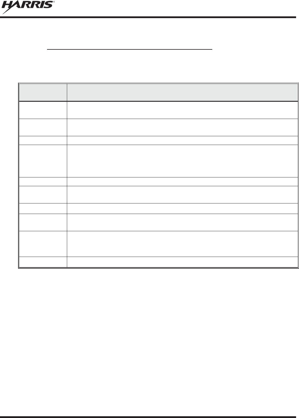
MM-012125-001, Rev. M
47
5.15 KEYPAD
5.15.1 Keypad Commands (System Model Control Head)
To perform a command from the keypad, press the * key followed by one of the pre-set function keys as
follows:
Table 5-5: Keypad Function Commands
KEYPAD
COMMAND
FUNCTION
*0
Log off command:
*0## (logs the user off the system). See page 38
for additional
information.
*1
Login command:
*1<User ID> # <Password> #
(required for encryption). See page
37
for additional information.
*2
Status Message: *2 <0...9> #.
*4
Enter Scene of Incident Mode (SOI) on specified channel and band:
*4#<
ccc>#<bb># where ccc is the SOI channel number and bb
is the number assigned
to each frequency band.
Press *40# to exit SOI mode.
*5
RTT Message: *5 <0...9> #.
*7
Initiate Selective Alert command:
*7<Target ID>#[Choose Message]#
. See page 57
for additional information.
*8
Radio-to-Radio Call command:
*8<Selective call number># (PTT to dial).
*9
Public Switched Telephone Network (PSTN) Call command:
*9 <telephone
number
># (PTT to dial). See page 59 for additional information.
*32
Begin Manual Encryption command:
*32<Pre-Determined Encryption Key >#
1
– 16 digit encryption key for 128 bit encryption; 17 –
32 digit encryption key for 256
bit encryption. See page 62 for additional information.
*33
End Manual Encryption command
: *33#
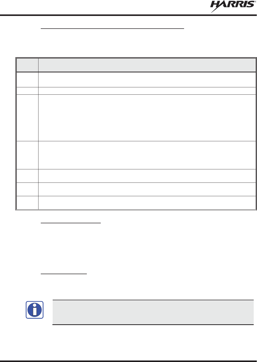
MM-012125-001, Rev. M
48
5.15.2 Quick Buttons (System Model Control Head Only)
Quick Keys are a two-button sequence that gives the radio user quick access to certain menu items. Quick
keys act as a toggle function.
Table 5-6: Quick Button Functions
QUICK
KEYS
FUNCTION
1#
Transition to ECP/XGP mode.
If ECP/XGP is not loaded in the radio, the radio displays “No App.”
2#
Stealth Mode On/Off.
3#
Scan Mode On/Off.
x
If the Scan Mode is Normal when the Scan Mode is toggled Off, the Scan Mode is
Normal
when toggled On again.
x
If the Scan Mode is Fixed when the Scan Mode is toggled Off, the Scan Mode is Fixed
when Scan Mode is toggled On again.
x
If the Scan Mode is Off when the radio boots up, the Scan Mode is Normal when Scan
Mode is toggled On.
4#
Lights/Tones On/Off.
This turns the TX/RX LEDs and Side Tones On/Off.
If the radio is in Stealth mode, this quick button is disabled since the user is not able to turn on
the light/tones in Stealth Mode.
5#
This quick key sequence is used to set the current active profile to the default profile in the
personality as defined in the UAS.
7#
This quick key sequence is used to transmit the RTT Automatic Normal Message to the
console.
8#
This quick key sequence is used to transmit the RTT Automatic Priority Message to the
console.
5.15.3 Keypad Lock/Unlock
To lock or unlock the keypad:
1. Press the MENU button.
2. While the MENU button is pressed, within one second press the OPTION button.
3. A brief message is displayed on the 2nd line of the display (Kypd Lck, Kypd Unlck).
5.15.4 Password Entry
Password entry requires a system model control head. Password characters are encrypted on the display
using symbols to indicate the entry. The encryption symbols for each entry appears in the display as they
are scrolled through, for example: '-' and '+'. Press the # key twice to complete the entry process.
If the password is wrong, the radio does not successfully register with the network for
wide area voice reception. The radio can still be used in single
-site mode.
NOTE

MM-012125-001, Rev. M
49
5.15.5 DTMF Overdial
Using the keypad on a System Model, the radio can transmit DTMF tones corresponding to
numbers/characters 0 - 9, *, and # on the keypad. To overdial numbers/characters, transmit by pressing
and holding the PTT button and then press the corresponding keys (one at a time) on the keypad.
5.16 CHANGE THE ACTIVE PROFILE
The radio can store up to sixteen (16) standard profiles, one of which is the currently active profile. To
change the currently active profile:
1. Scroll through the menu until “ProfileMenu” is displayed.
2. Use to scroll through the list of available profiles.
3. The profile becomes active when selected for longer than two (2) seconds, when the MENU is
pressed, or when the menu is changed.
5.17 ENABLE/DISABLE VOLUME SIDE TONE
The Volume Side Tone sounds when adjusting the volume control.
To enable or disable this tone:
1. Power off the radio.
2. Press and hold the B button while turning the radio on.
5.18 CHECK OR CHANGE THE SELECTED TALK GROUP
Each profile stored in the radio can have up to sixteen (16) talk groups. One talk group within the
currently active profile is set as the “selected talk group.” For the radio user, the selected talk group is
typically the focus of most voice transmissions and receptions. There are two ways to change the selected
talk group:
First Method:
1. Scroll through the menu until “TalkGrpMenu” appears on the bottom line of the display. The
currently selected talk group appears in the top line of the display.
2. Use to scroll through the available list of talk groups in the active profile. This list is
determined by the OpenSky network administrator.
Second Method:
From the dwell display, use the talk group selection knob or to scroll through the available list of
talk groups in the active profile.
5.19 ADJUST DISPLAY AND BUTTON BACKLIGHT BRIGHTNESS
1. Scroll through the menu until “Bright Menu” appears.
2. Use to increase or decrease brightness. Display and button backlight brightness immediately
dims or brightens.
Or
If enabled via programming, the control increases/decreases brightness.

MM-012125-001, Rev. M
50
5.20 STEALTH MODE
For some users, it is important to be able to turn off the radio’s display lights, button backlighting, volume
and side tones, but not the radio traffic. For example, in covert operations, lights and sounds could
inadvertently expose an otherwise unobservable radio user. For this purpose, the radio has a Stealth
feature that disables the radio display light, indicator light, and audible side tones.
When Stealth Mode is on, the radio continues to scan the programmed list of talk groups and the user can
key-up on the selected talk group. All buttons are disabled except for PTT, Emergency, 2# and MENU.
Since the screen is blank the user cannot see the result of other button presses.
5.20.1 Enable Stealth Mode
1. Scroll through the menu until “StealthMenu” appears.
2. To immediately turn Stealth Mode on, press (+) or (-) with .
Or
Press quick button command 2# on the System Model control head.
5.20.2 Disable Stealth Mode
To turn Stealth Mode off, press quick button command 2# or the MENU button on the radio’s front panel.
5.21 ADJUST SIDE TONE AUDIO LEVEL
The radio sounds confirming tones called “side tones” when its buttons are pressed. Most users find this
audible confirmation helpful when navigating the menus. Side tone audio level can be adjusted or turned
completely off using the “Side Menu.”
For covert operations, it may be necessary to turn off side tones. For safety’s sake, turning off the radio
during covert operations is not recommended.
To temporarily disable the side tones that could expose the user’s presence and position, use the menu
buttons to access the “Side Menu” and select “Off” from the menu choices.
If the radio is operating properly but side tones are not heard when the menu buttons are pressed, the side
tones are probably turned off. To turn them back on, access the “Side Tone” menu and select a setting
other than “off.”
Use the following procedure to set side tone level:
1. Scroll through the menu until the “Side Menu” appears in the bottom line of the display.
2. Use to change to the desired level (Off, Low, Medium, and High). To turn side tones
completely off, use the “Off” setting.
MM-012125-001, Rev. M
51
5.22 CHANGE OPERATING MODE
1. Scroll through the menu until “App Mode” appears in the bottom line of the display.
2. Use to choose an available mode. Press MENU and confirm (Y/N) with and press
MENU again.
Or
Preset button C can be configured via programming to reboot the radio into a particular application mode.
Or
Quick Button command 1# transitions the radio to ECP/XGP mode. If ECP/XGP mode is not loaded in
the radio, the radio displays “No App.”
5.23 RECEIVE AND TRANSMIT VOICE CALLS
As soon as the radio completes the startup/login/provision/self-test sequence and registers on the
OpenSky network, voice calls from talk groups in the active profile are audible.
5.23.1 Receive a Voice Call
The
Alias/User ID/Talk Group
name are only displayed if that dwell display option is
selected
using the MENU button. For example if the user sets
the dwell display option
to profile, the profile continue
s to be displayed when a call is received.
No action is required to receive a voice call. The display responds to incoming voice calls as follows:
x When the dwell display is set to received talk group, the Scan Mode is Normal or Fixed:
a. If the received talk group matches the selected talk group, then the alias (if available) or user ID
of the incoming caller is displayed.
b. If the received talk group does not match the selected talk group, then the received talk group
name is displayed.
x When the dwell display is set to received talk group and the Scan Mode is None, the radio only
receives voice on its selected talk group. When the call is received, the alias (if available) or the user
ID of the incoming caller is displayed.
x When the dwell display is not set to received talk group, then there is no display indication of an
incoming call.
A radio receiving a System All Call displays “All Call” instead of the ali
as.
A radio
not transmitting on a
talk group in emergency status drops
all other calls to scan into
an
All Call.
Refer to Section 5.27 for detailed information on talk group scanning. Refer to Section 5.32 for detailed
information regarding sending and receiving encrypted calls.
NOTE
NOTE
MM-012125-001, Rev. M
52
5.23.2 Transmit a Voice Call
Transmit a voice call as follows:
1. Turn the radio on.
2. If required, login to the network using a user ID and password (see Section 5.4).
3. Select the desired talk group for transmitting on.
4. Press and hold the Push-to-Talk (PTT) button on the hand-held microphone, pause for a moment,
and then speak normally. For maximum clarity, hold the microphone approximately 2 inches from the
mouth and do not shout or whisper into it. If the call is queued by the network, wait for the grant tone
to sound before speaking.
5. Release the PTT button when finished speaking.
Refer to Section 5.32 for detailed information regarding sending and receiving encrypted calls.
5.24 ADJUST AUDIO TREBLE LEVEL
The tone of received signals can be adjusted using the radio’s “Treble Menu” as follows:
1. Scroll through the menu until “Treble Menu” appears. The radio’s current treble level setting
indicates in the top line of the display. There are four levels available: low, medium, medium-high,
and high.
2. Use to increase or decrease treble level.
3. Press the MENU button or wait a few seconds to return to the Dwell Display.
5.25 INTERCOM MODE
The optional intercom mode gives users at multiple control heads connected to the same radio the ability
to communicate with each other without transmitting over-the-air. Turn intercom mode on and off using
the “INTERCOM” menu as follows:
1. Scroll through the available menu items until “INTERCOM” appears in the display.
2. Use to toggle between “On” and “Off.”
When intercom mode is turned on:
x Incoming voice calls override intercom communications for the duration of the voice call. The radio
and associated control heads remain in intercom mode and intercom communications resume when
the voice call ends.
x “TG: INTERCOM” appears in the control head’s display when talking on the intercom. This indicates
microphone audio is not sent out on the selected talk group; rather, it remains localized between the
radio control positions (i.e., the control heads connected to the mobile radio).
x If a call exists on the currently selected talk group when a PTT button is pressed at one of the control
heads, “TG: in use” appears in the display to indicate intercom mic audio cannot preempt the call on
the talk group.
A user at a radio with only one control head/front panel can turn intercom mode on. In
this case, pressing the microph
one’s PTT button does NOT
send microphone audio
anywhere.
CAUTION
MM-012125-001, Rev. M
53
5.26 TALK GROUP LOCK OUT
There are two ways of focusing voice communications by suppressing calls from talk groups in the
currently active profile:
1. No Scan. By turning scan off (selecting “No Scan” via the “ScnModeMenu”), only the selected talk
group is audible.
2. Lock Out. By locking out selected talk groups, the “chatter” of the locked out talk groups cannot be
heard. This focuses the user’s scanning resources to calls only on desired talk groups.
Talk group lock out is a scan-related feature. With lock out, one or more talk groups in the active profile
can be temporarily disabled from being scanned. Calls are not received on locked-out talk groups. Lock
out settings are not retained between profile changes or when the radio is power cycled.
Lock out is a listening (receive) function and only blocks received calls on locked out
talk groups. Lock out does not affect transmit capability. The above methods do not
apply to recent emergency lock outs.
Only talk groups in the active profile can be locked out, since they are the only talk groups whose voice
calls can be heard on the radio.
P1
, P2, and P3 talk groups cannot be locked out.
The default emergency and emergency-capable talk groups can be locked out if they are NOT in an
emergency state. If a talk group is locked out and is subsequently changed to the currently selected talk
group, it is automatically unlocked by the radio so the user can hear calls on the talk group. The radio may
be configured so all talk groups are automatically locked out by default. In this case, they must be
manually unlocked, if desired.
5.26.1 Lock Out a Talk Group
1. Scroll through the menu until “LockOutMenu” appears in the bottom line of the display. The name of
a talk group in the currently active profile appears in the top line.
2. Use to scroll through the list of talk groups, if any, until the desired talk group for lock out
appears in the top line of the display.
3. Press the MENU button to lock out the displayed talk group. A less than symbol (<) appears next to
the talk group’s name.
4. Repeat steps 2 and 3, as needed, to lock out additional talk groups.
The dwell display re-appears a few seconds after button presses end.
While scrolling through talk groups in the active profile, the only talk groups that appear in the
“LockOutMenu” are those in the active profile.
5.26.2 Unlock a Talk Group
1. Scroll through the menu until “LockOutMenu” appears in the bottom line of the display. The name of
a talk group in the currently active profile appears in the top line.
NOTE
NOTE
MM-012125-001, Rev. M
54
2. Use to scroll through the list of talk groups, if any, until the talk group desired for unlocking
appears in the top line of the display. A less-than symbol (“<”) appears next to the name of a talk
group that is currently locked out.
3. Press the MENU button to unlock the talk group. The less-than symbol (“<”) next to the name of the
talk group disappears. The dwell display appears as soon as the radio acknowledges the selection.
x
Changing the active profile removes any lock outs you have made.
x
Turning off the radio removes any lock outs you have made.
5.27 SCANNING
Three scanning modes are available for the radio, but only one can be active at any time. Changing the
scanning mode changes the way the radio scans voice calls for all of profiles in the radio personality, no
matter which profile is or becomes active.
As described in Table 5-7, the choice of scanning mode changes the span of communications with all the
talk groups in the radio’s profiles, but does not affect interaction with the talk groups.
Table 5-7: Scan Modes
SCAN
MODE
EXPLANATION
No Scan
Eliminates distractions.
Full communications (transmit and receive) on selected talk group.
No calls rec
eived from other talk groups.
Normal
(Default)
The user can scan all talk groups in the active profile that are not locked out as long as
there is demand on the site.
Priority (P1
, P2, and P3) groups are user selectable.
Receive calls from more than one
talk group, if available from the current site.
Allows dragging of the selected talk group, P1, P2,
P3,
and default emergency talk
groups to the site on which the radio is registered. (If other calls are available at the site,
they also can be heard but th
ey are not be actively dragged.)
The default emergency talk group, as well as any emergency
-
enabled talk groups, is only
dragged if it is in emergency mode.
Fixed
Functions the same as Normal Scan Mode, except the priority groups are fixed to the
selected
profile’s pre-defined P1 and P2 groups (configured via the UAS).
5.27.1 Check or Change Active Scan Mode
The currently active Scan Mode does not appear in the dwell display. To check it, access
“ScnModeMenu” and observe it in the top line of the display. To change the active Scan Mode:
1. Scroll through the menu until “ScnModeMenu” appears in the display.
2. Use to scroll through the scan options until the desired mode appears. See Table 5-7.
Or
Use the quick button option 3#.
NOTE

MM-012125-001, Rev. M
55
5.27.2 Scan Priority
The following lists the scanning priority order (from highest to lowest):
x System All Call
x Selected talk group in emergency state
x Default emergency group in emergency state
x Selected talk group
x Emergency capable group in emergency state
x Priority 1 talk group
x Priority 2 talk group
x Priority 3 talk group
x Other (non-priority)
5.27.3 Change Priority 1 and Priority 2 Talk Groups
Follow this procedure to set talk groups in the current profile as the Priority 1 or Priority 2 talk group:
1. Scroll through the menu until “Priority1” or “Priority2” appears in the bottom line of the display
(Priority 1 group has higher priority than the Priority 2 group. The talk group currently set as the
priority talk group appears in the top line of the display.
2. Use to select a new priority talk group.
3. Press the MENU button to set the newly selected talk group as the priority talk group.
5.27.4 Change Priority 3 Talk Groups
Follow this procedure to set talk groups in the current profile as Priority 3 talk groups:
1. Scroll through the menu until “Priority 3” appears in the bottom line of the display. The name of a
talk group in the currently active profile appears in the top line.
2. Use to scroll through the list of talk groups, if any, until the desired talk group for Priority 3
appears in the top line of the display.
3. Press the MENU button to select/deselect the displayed talk group as a Priority 3 talk group. A less
than symbol (<) appears next to the talk group’s name.
4. Repeat steps 2 and 3, as needed, to select/deselect additional talk groups.
5.28 MAKE SELECTIVE CALLS
Selective calling is a feature that allows two radio units to obtain and utilize an independent voice path for
a private call. Radios can be configured to both initiate and receive Selective Calls or to only receive
Selective Calls.
In the OpenSky system, a source radio can be configured to initiate Selective Calls through a pre-
programmed list in memory. This method uses the “speed dial list” set up by the OpenSky network
administrator and provisioned as part of the registration process.
In addition, a properly equipped source radio can initiate a Selective Call to any radio in the system by
entering the ten-digit voice user ID (which looks like a telephone number) of the target device. Entering a
MM-012125-001, Rev. M
56
Selective Call number without using the speed dial feature requires a system model control head (Figure
5-1). See Section 5.14 for more detail.
Selective calls are terminated if an emergency
is declared. The network limits
Selective
Call
s to ten (10) minutes maximum.
Table 5-8 lists and defines the messages that may be displayed by the radio during a Selective Call.
Table 5-8: Status of Selective Call
STATUS
MESSAGE
DEFINITION
Busy
Peer is involved in another selective/PSTN call.
Disconnect
Selective/PSTN call was terminated for unknown reason.
Network Err
Selective/PSTN call cannot continue because of an unspecified network error.
Reject
Peer or this user declined request to establish selective/PSTN call.
Unavailable
Peer cannot be reached for selective/PSTN call.
Calling
Calling peer (i.e., for selective or PSTN calls).
Connecting
Establishing selective/PSTN call with peer.
Hangup
Peer or this user terminated selective/PSTN call.
Lim 10 min
Selective/PSTN call limited to 10 minutes.
Timing Out
Selective/PSTN call has 10 seconds remaining before limit is reached (shown for 5
seconds).
Sel Call
Selective call is active.
5.28.1 Manually Dial a Selective Call (System Model Control Head)
1. Press *8 on the keypad.
2. Enter the number of the radio to be called (e.g., 027-001-0006). If the region number (first 3 digits;
027 in this example) is the same as this radio’s region number, these digits do not need to be entered.
Likewise, if the region and agency numbers (first 6 digits; 027-001 in this example) are the same as
this radio’s numbers, these digits do not need to be entered. Leading zeros can also be ignored.
3. Press and release the # key.
4. Wait approximately two (2) seconds.
5. Press and release the PTT button to initiate the Selective Call request. When the called party accepts
the call, press PTT again and begin speaking.
5.28.2 Speed Dial a Selective Call
Speed dial numbers are defined and provisioned by the OpenSky network administrator
and cannot be manually entered into the radio by the user. Contact the administrator if
changes to the speed dial list are required.
1. Scroll through the menu until “SpeedDial” appears in the bottom line of the display.
2. Using , scroll through the pre-programmed speed-dial numbers until the desired number
appears in the display.
NOTE
NOTE

MM-012125-001, Rev. M
57
3. Press and release the PTT button to ring the other user.
a. The ring tone is sounded.
b. If the other user accepts the call, the called user’s alias appears in the initiating caller’s display.
The two are now in a private call until one ends the call, the call is terminated due to an initiated
emergency, or the maximum time limit of ten (10) minutes is reached.
4. To end the call, press the # button or (-) using .
5.28.3 Receive a Selective Call
When someone calls in from another radio using the Selective Call function, a ring sounds in the speaker
and/or headset. Press up or down using or any number key to accept an incoming Selective Call.
Press the microphone’s PTT button when speaking (transmitting) to the caller.
Press the # button or (-) using to reject an incoming Selective Call.
A Selective Call is interrupted if an emergency is declared on a monitored talk group.
5.28.4 Terminate a Selective Call
Press the # button or (-) using to terminate an incoming Selective Call.
5.29 SELECTIVE ALERT
Selective alert messaging is an OTP feature allowing one of up to eight (8) pre-programmed text
messages (refer to Section 5.29.3) to be sent from one radio to another. The user specifies a destination
radio’s User ID, selects one of the pre-programmed text messages, and then transmits it to the destination
radio. The message delivery system adds time-of-day information and forwards the message to the
destination (receiving) radio. The sending radio receives a brief message noting the status of the
transmission. Refer to Table 5-9 for a list of possible status messages.
The first few characters of a message are part of the message text entered when the message is
programmed. This programming is performed by the system or network administration personnel.
Messages successfully received by the destination radio are stored until deleted or until the radio is power
cycled.
5.29.1 Send Selective Alert Messages
The destination radio’s User ID can be selected via the menu or via the keypad on the system model
control head.
Menu Button Method:
1. Scroll through the menu until “AlertDest” (Alert Destination) appears in the bottom line of the
display. The current speed dial number scrolls on the top line.
2. Use to change to a different speed-dial number.
3. When the desired speed-dial number appears, press the MENU button to activate the selection.
4. Choose and send the message.
Keypad Method (System Model Control Head):
To select the destination radio’s User ID using the keypad, perform the following:

MM-012125-001, Rev. M
58
1. Press *7 on the keypad. “AlertDest” appears in the display.
2. Enter the number of the destination radio (e.g., 027-001-0006) using the DTMF keypad. If the region
number (first 3 digits; 027 in this example) is the same as this radio’s region number, these digits do
not need to be entered. Likewise, if the region and agency numbers (first 6 digits; 027-001 in this
example) are the same as this radio’s numbers, these digits do not need to be entered. Leading zeros
can also be ignored. Refer to Section 5.14.
3. Press the # key to enter the number.
Choose and Send the Message
After specifying the destination radio’s User ID (Section 5.29.1), the radio automatically allows you to
choose a message. The current message scrolls across the top line of the display. To choose a message:
1. Scroll through the message list using . The next available message in the list is displayed.
Pause between each arrow button press to observe the entire message as it scrolls across the top line
of the display.
2. To select and send the displayed message, press the MENU button, or press the # button on the
keypad.
3. The status of the sent message is momentarily displayed (Table 5-9).
Table 5-9: Status of Selective Alert
STATUS MESSAGE
DEFINITION
Alert Sent
Alert message successfully sent to target.
Delivered
Alert message passed to network.
Delivering
Delivering alert message to target.
New alert
New alert message received.
No alerts
No alerts are available.
Busy
VNIC congested and cannot deliver message at
the current time.
Dest Down
Destination home VNIC down.
Ignored
Destination is either non-responsive or does not
care to respond.
Inv Option
Distribution option is invalid.
Not Reg
Destination is not registered.
Partial
Not all destination ESN instances reachable.
Unauth Alrt
Unauthorized service function; initiator is not
authorized to send the selected service message.
Unknown Msg
Unknown status received from VNIC.
Unreachable
Alert destination cannot be reached.
5.29.2 Receive Messages
When a selective alert message is received by a radio, a four-beep tone (one low, two high, and one low)
is heard and “New alert” flashes until the new message is read. Up to eight (8) received messages are
stored. If another message is received, the first (oldest) message is automatically deleted to make room for
new incoming messages.

MM-012125-001, Rev. M
59
Display Received Messages
1. Scroll through the menu until “AlertsRecvd” (Alerts Received) appears in the bottom line of the
display. “No alerts” or the last received (newest) message appears in the display. It is preceded by the
time the message was received, and the sender’s name/alias.
2. View other received messages using .
3. To delete the message currently being viewed, press the MENU button.
Delete Received Messages
To delete a received message:
1. Display the message.
2. Delete the message by pressing the MENU button.
3. Confirm the deletion by pressing the MENU button again.
5.29.3 Define Pre-Programmed Messages
All selective alert messages are pre-defined by the radio system’s maintenance personnel. These messages
are sometimes referred to as “canned” messages. Custom selective alert messages cannot be created by
the radio user. The entire selective alert message can include up to 99 text characters.
5.30 TELEPHONE INTERCONNECT CALLS (SYSTEM MODEL CONTROL
HEAD)
5.30.1 Place an Interconnect Call
If the radio system is equipped with Public Switched Telephone Network (PSTN) interconnect
equipment, telephone calls can be made from the M5300 using this procedure:
1. Press the * 9 keys.
2. Enter the telephone number. Ignore dashes/spaces and precede the number with any required access
digits such as a 1 for long distance.
3. Press the # key.
4. Wait a few seconds and then press and release the mic’s PTT button to initiate the call. An initial ring
tone plays indicating call initiation. Once the gateway picks up the call, another ring tone sounds.
5. When the caller answers, press the PTT button when speaking and release it to listen to the caller.
6. To hang-up, press the # button or (-) using .
5.30.2 Receive an Interconnect Call
When receiving an Interconnect Call, a ring sounds in the speaker and/or headset. Press up or down using
or any number key to accept an incoming Interconnect Call. Press the microphone’s PTT button
when speaking (transmitting) to the caller.
Press the # button or (-) using to reject an incoming Interconnect Call.

MM-012125-001, Rev. M
60
5.31 EMERGENCY COMMUNICATIONS
The M5300 mobile radio can transmit both emergency voice calls and emergency alerts over the entire
network. OpenSky handles emergency calls and alerts with the highest priority.
For critical voice communications, an emergency call can be raised on the default talk group or the
currently selected talk group by “declaring” an emergency on the talk group. The exact talk group is
determined by the currently active profile. After successfully declaring an emergency on a talk group, the
declaring radio’s microphone remains “hot” for a predetermined amount of time. In other words, the radio
transmits audio for a period of time even when the microphone’s PTT button is not pressed. An
emergency talk group is provided greater priority and infinite hang-time by the radio system’s
infrastructure. Hang-time is the maximum duration of quiet time between transmissions on the talk group
before the infrastructure assets are automatically taken away. Because an emergency call is handled on a
talk group, it is received by all radios and consoles monitoring the talk group.
An emergency alert is a data message sent by the radio to the MIS console (or any console capable of
receiving it). It identifies the radio declaring the emergency, and the radio’s location (if the radio is
equipped with a GPS receiver). Voice audio is not automatically transmitted during the emergency if the
administrator configures the radio for alert notification only.
5.31.1 Declare an Emergency Call or Alert
1. Press the red emergency button on the radio to enter emergency mode. The emergency is raised after
the emergency raise delay [default is one (1) second].
x If the active profile of the unit initiating the emergency is configured for Emergency Alert, the
emergency alert signal is sent to registered alert servers, such as the dispatcher console.
x If the active profile of the unit initiating the emergency is configured for Emergency Call, the
talkgroup is placed into emergency status notifying other radios and the emergency alert signal is
sent to the dispatcher console.
x If the emergency behavior of the active profile is Current, the active, selected voice group
becomes the default emergency voice group.
x If the emergency behavior of the active profile is Default, the radio moves to the default
emergency voice group of the profile and this talk group becomes the select talk group.
2. The display alternates between “Emergency” and whatever option is selected for the 2nd line of the
dwell display.
If the attempt is unsuccessful, “E-PEND” flashes periodically and a retry is queued for 10 seconds. If
unsuccessful because of lost sync, retry occurs immediately upon reacquiring sync. On each retry attempt,
radio temporarily displays “E-RETRY.” This process repeats until the emergency is successfully
declared.
5.31.2 Silent Emergency
When this feature is enabled and an emergency call or alert is declared by pressing the emergency button,
the radio does not play a tone and displays an abbreviated emergency message (default is EBA). This
feature is enabled or disabled via programming or via the menu.
If the Silent Emergency feature is enabled or disabled via programming, the setting
survive
s power cycle. Enable/Disable selection via the menu does
NOT survive power
cycle and the enable/disable state revert
s to the programmed setting at power up.
NOTE
MM-012125-001, Rev. M
61
5.31.3 Clear an Emergency Call or Alert
Check with the system administrator to ensure that the radio is programmed to allow an
emergency to be cleared.
If enabled via programming, clear an emergency by:
1. Pressing and holding the CLR/CLEAR button and simultaneously pressing the emergency button.
2. After the Emergency Cleared Tone sounds, release both buttons.
If the radio is in
Stealth Mode, clearing the emergency takes the radio out of
Stealth Mode.
5.31.4 Receive an Emergency Call
Upon receiving an emergency call declared by another radio:
x An emergency tone sounds in the radio’s speaker/headset (three short high-pitched beeps).
x “EMERGENCY” flashes in the display if the radio is not in Stealth Mode. When receiving voice in
an active emergency, the flashing “EMERGENCY” is inhibited so that the alias of the sender can be
seen.
x On receiving radios with the emergency talk group selected, the alias of the sending party is displayed
for 5 seconds during the open-mic period, then the word “Emergency” flashes on the second line of
the display and continues until the emergency state ends.
x If Scan Mode is set to “No Scan” and the emergency was declared on the selected talk group, audio
on the emergency talk group is heard in the speaker/headset. See page 54 for additional information
on “No Scan” operation.
x If Scan Mode is set to “No Scan” and the emergency was declared on a talk group other than the
selected talk group, the emergency talk group (identified by an “*”) must be selected before audio on
it is heard in the speaker/headset.
x If Scan Mode is set to “Normal” and the emergency was declared on the selected talk group, the
selected/emergency talk group’s name remains in the top line of the display. Audio on the emergency
talk group is heard in the speaker/headset.
x If Scan Mode is set to “Normal” and the emergency was declared on a talk group other than the
selected talk group, the emergency talk group’s name appears in the bottom line of the display. Audio
on the emergency talk group is heard in the speaker/headset.
x The declaring radio's alias appears in the bottom line of the display when the emergency talk group is
selected.
x An emergency call can be dismissed as described in the following section.
A radio declaring an emergency on a talk group has a “hot” mic time period of typically
ten (10) seconds just
after it declares the emergency. This time period may be adjusted
by system or network administration personnel on a per radio basis.
NOTE
NOTE
NOTE
MM-012125-001, Rev. M
62
5.31.5 Dismiss an Emergency Call
An emergency is dismissed for a configurable amount of time only (default = 5 minutes).
To ignore an emergency call declared by another radio user:
1. Scroll through the menu until “EmgDismiss” appears in the display.
2. Press until the talk group in the emergency state appears, as indicated by an asterisk (*)
following the talk group’s name.
3. Press the MENU button.
The emergency dismiss timer is cleared when the emergency is cleared.
5.32 ENCRYPTION
In the OpenSky network, both data and voice use a 128-bit or 256-bit key encryption standard published
by the Federal Information Processing Service (FIPS), called Advanced Encryption Standard (AES). AES
is approved by the U.S. Department of Commerce for encryption of classified materials.
When encryption is enabled on the network, data is encrypted from the MDIS to the Mobile End System
(MES) (e.g., M5300 mobile radio). This form of encryption provides air-link security.
Voice encryption is handled either automatically or manually. Automatic encryption is initiated through
the Unified Administration Server (UAS) for a specific talk group and requires nothing from the user.
Manual encryption is initiated by two or more radio users and requires system model control heads. Both
methods of encryption are discussed in the following sections.
5.32.1 Automatic Encryption
For automatic encryption, a network administrator selects the talk group to be encrypted at the interface to
the UAS. Once the talk groups have been selected and identified as secure, credentials for key generation
are generated automatically by the system and provisioned to authorized users. This process requires that
authorized users login to the network and be authenticated. Encryption keys require no manual handling
and are never sent “in the clear” over any network interface or air-link.
1. “Pls Login” appears displayed in the bottom line of the dwell display.
2. Login normally using the keypad on a system model control head to enter User ID and Password.
If a user is engaged in a call on a talk group encrypted at the network administrator level, “Secure Call”
appears in the bottom line of the dwell display if the user is logged in to that talk group.
If a secure call is in progress elsewhere and the user has not logged in, the bottom of the dwell display
alternates between “No Access” and the alias of the radio that is currently engaged in the secure call.
R
adios can be programmed to automatically login and enable encryption.
NOTE
NOTE
NOTE
MM-012125-001, Rev. M
63
5.32.2 Manual Encryption (System Model)
Two or more users can manually encrypt a call, if enabled, without an established encrypted talk group. A
pre-determined key is required at each radio.
The key must be pre
-
determined by the users prior to making a manually encrypted call
on a talk group and is entered into the radio using the keypad. For 128 bit encryption, this
key is between 1 and 16 digits. For 256 bit encryption, this key is between
17 and 32
digits.
If two communicating radios have different (manually
-
defined) keys, receive audio at
each radio sounds garbled.
With manual encryption enabled, unencrypted radio users on the talk group can still make standard voice
(unencrypted) calls on the talk group. However, if an unencrypted user attempts to transmit on the talk
group when one of the encrypted users is already transmitting on the talk group, the unencrypted radio
sounds a deny tone and “No Access” appears in the display. Also, the encrypted user can hear standard
unencrypted calls, but cannot respond while still manually encrypted.
Do
not
set a talk group for manual encryption if it has been set for encryption by the
network administration personnel.
Perform the following to transmit or receive manually encrypted calls:
1. Press *32 on the keypad.
2. Enter the key (1 – 16 digits for 128 bit encryption; 17 – 32 digits for 256 bit encryption).
3. Press the # key.
4. To end manual encryption, press *33#.
If a user is engaged in a call on a talk group that has been manually encrypted at the radio level, the user
sees “Secure Call” on the bottom of the dwell display.
If a secure (encrypted) call is in progress, and the user has not entered the key, the bottom of the dwell
display alternates between “No Access” and the alias of the radio that is currently engaged in the secure
call.
Once the user has terminated manual encryption, “UnSecure” appears temporarily in the bottom line of
the dwell display.
5.33 PRESET BUTTONS
The front panel contains three buttons labeled A, B, and C. By holding one of these buttons down for
approximately three (3) seconds, the following current information is saved to the function of that button:
x Currently selected Priority 1, Priority 2, and Priority 3 talk groups
x Currently selected profile
x Currently selected talk group
x Lock outs
x Scan state
x Intercom mode
NOTE
CAUTION

MM-012125-001, Rev. M
64
After changing systems, groups, scan state, etc., simply press the preset button to restore the settings.
Presets are saved and restored to/from non-volatile memory. Changing the User ID (login in as a different
user) clears the presets since they are stored on a per-user basis. Changing control heads does not recall
presets for the previous control head.
Preset button C can be configured via programming to reboot the radio into a particular
application mode, toggle the external speaker OFF/ON, toggle the Public Address
OFF/ONN
,
or toggle the Selective Call Alert. Contact your system administrator to
determine if this feature is enabled in your radio.
5.34 STATUS MESSAGES
If enabled via programming, the radio can transmit a pre-programmed status message. Section 8.30.1
describes how to send a status message via the keypad and Section 8.30.2 describes how to send a status
message via the menu.
5.34.1 Send Status Message via the Keypad (System Model Only)
1. Press *2 <0…9> # on the keypad.
2. A Status message can be associated with each key (0 – 9). This text is displayed on the first line of the
display when the key is pressed until another key is pressed.
x If no messages have been configured, “No Messages” is displayed.
x If a message is not assigned to a key, “No Entry” is displayed for the keypad sequence.
x You can press multiple keys to select the desired Status message.
3. The # key terminates the keypad sequence and sends the currently selected status message. If no
messages have been configured or no message is associated with the key, no message is sent and an
error tone is played.
Press the * key to cancel the keypad sequence.
5.34.2 Send Status Message via the Menu
1. Scroll through the menu until “Status Msg” appears and press MENU. If no messages have been
configured, “No Messages” is displayed.
2. Scroll through the available messages using . The configured Status message is displayed on
the 1st line of the display.
3. Press the MENU button to send the currently selected message. If no messages have been configured,
no message is sent and an error tone sounds.
Press up or down with to cancel status message selection.
5.35 REQUEST TO TALK (RTT) MESSAGES
If enabled via programming, the RTT message feature allows you to send either a short service message
to the VNIC. Section 5.35.1 describes how to send an RTT message via the keypad and Section 5.35.2
describes how to send an RTT message via the menu. Note that only one RTT message can be
programmed into the radio.
NOTE
MM-012125-001, Rev. M
65
5.35.1 Send RTT Message via the Keypad (System Model Radios Only)
1. Press *5 <0…9> # on the keypad. The key associated with the RTT message (0-9) is configured via
programming.
2. This message is displayed on the first line of the display when the key is pressed until another key is
pressed.
x If no message has been configured, “No Message” is displayed.
x If a message is not assigned to the key, “No Entry” is displayed for the keypad sequence.
3. The # key terminates the keypad sequence and sends the currently selected RTT message. If no
message has been configured or no message is associated with the key, no message is sent and an
error tone is played.
Press the * key to cancel the keypad sequence.
5.35.2 Send RTT Message via the Menu
1. Scroll through the menu until “RTT Msg” appears and press MENU. If no message has been
configured, “No Messages” is displayed.
2. Use to select message. The configured RTT message is displayed on the 1st line of the display.
3. Press the MENU button to send the currently selected message. If no message has been configured,
no message is sent and an error tone sounds.
Press to cancel RTT message selection.
5.35.3 Send RTT Automatic Normal Message via the Quick Button
Press 7# buttons to send RTT Automatic Normal Message to the console.
5.35.4 Send RTT Automatic Priority Message via the Quick Button
Press 7# buttons to send RTT Automatic Priority Message to the console.
5.36 GPS COORDINATES
The radio’s current latitude and longitude coordinates may be displayed using the “GPS” menu. The
following procedure assumes a GPS antenna is connected to the radio and it is receiving adequate signals
from GPS satellites:
1. Scroll through the menu until the “GPS” menu appears in the bottom line of the display. Current GPS
coordinate latitude and longitude data continuously scrolls in the top line of the display in a
degrees:minutes:seconds format.
2. Use to change to another menu.
If the internal GPS receiver’s data is expired (30 minutes or more) or unavailable, the
radio uses the serving base station’s coordinates [GPS (Site) is displayed]. The GPS Menu
also indicates if the data is aged (2 minutes or more)
[GPS (Aged) is displayed].
NOTE
MM-012125-001, Rev. M
66
5.37 SCENE-OF-INCIDENT MODE
The Scene-of-Incident mode (SOI) is user-selectable. The SOI mode provides local repeater function (V-
TAC) with no network connection.
When operating in the SOI mode, the radio is disconnected from the
OpenSky
network.
Therefore, communications with radios and dispatch personnel on the network is not
possible.
Enter SOI Mode Manually Entering the Channel:
1. Scroll through the menu until the Client Mode menu appears.
2. Using , scroll until SOI is displayed.
3. Press the MENU button to confirm mode selection.
4. Using , scroll until “Manual Select Chan” is displayed and press MENU.
5. Using , scroll to edit the right-most digit and press MENU to advance to the next digit. Repeat
until the desired channel is entered.
6. The radio then prompts the user to edit the band. Use to edit the number assigned to the
frequency band and press MENU to confirm and enter the SOI mode.
Use the Client Mode menu to return to normal operation (Network Mode). The personality and profile in
use at the time the radio entered SOI mode is restored.
Enter SOI Mode Selecting Pre-Programmed Channel:
1. Scroll through the menu until the Client Mode menu appears.
2. Using , scroll until SOI is displayed.
3. Press MENU to confirm mode selection.
4. Using , scroll through a list of pre-programmed channels.
5. Press MENU to confirm channel and enter SOI mode.
Use the Client Mode menu to return to normal operation (Network Mode). The personality and profile in
use at the time the radio entered SOI mode is restored.
Enter SOI Mode (System Model Only):
1. Press *4#.
2. The radio prompts for the channel. Enter the channel number and press # to confirm channel.
3. The radio prompts for the band. Enter the number assigned for the desired frequency band and press #
to confirm.
4. The radio reverts to the dwell display.
If accepted, you are switched off the network and communicate locally through the V-TAC.
Press *40# or use the Client Mode menu to return to normal operation (Network Mode). The personality
and profile in use at the time the radio entered SOI mode is restored.
CAUTION
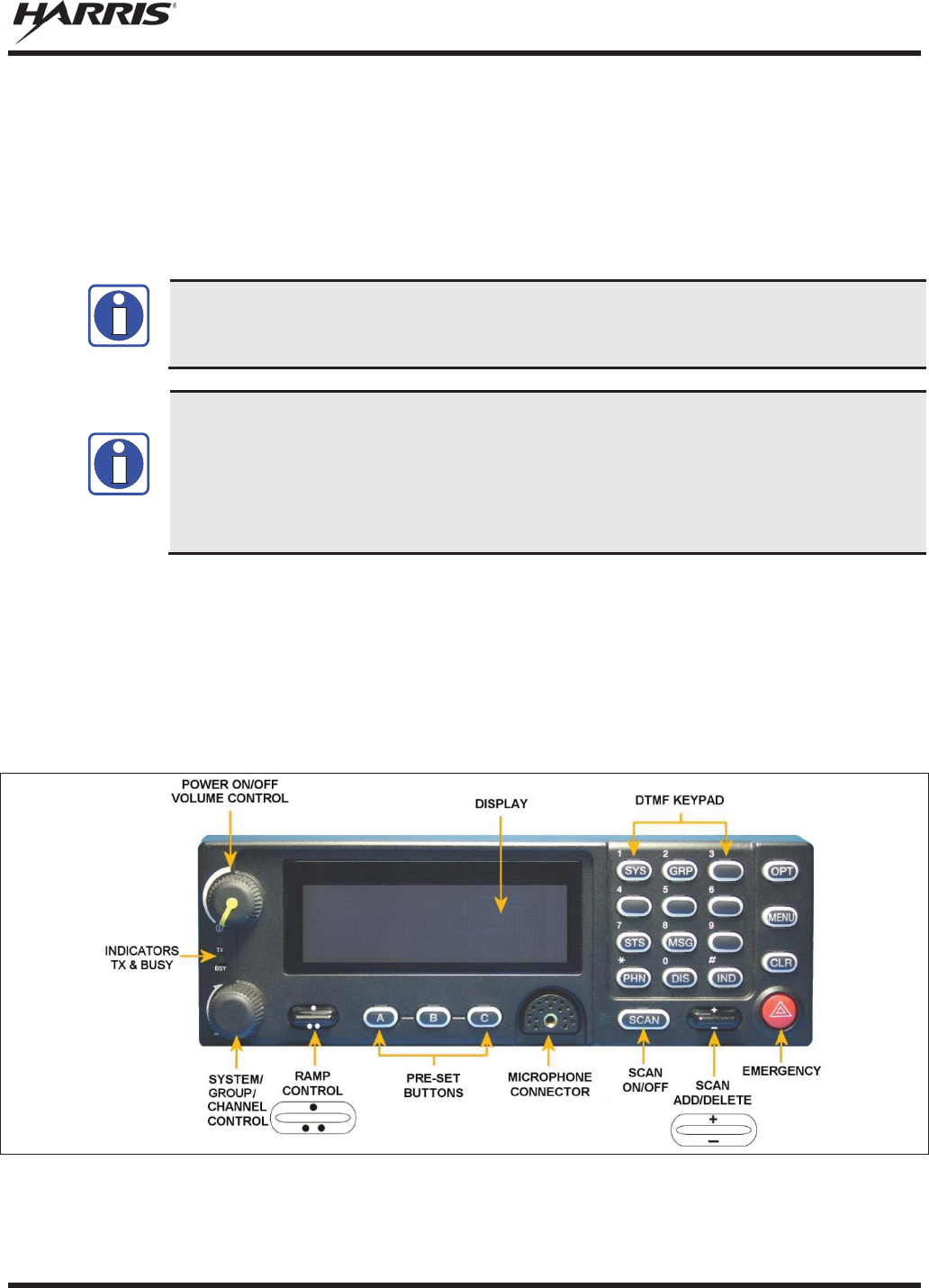
MM-012125-001, Rev. M
67
6. EDACS/CONVENTIONAL/P25 OPERATION
6.1 TURN THE RADIO ON
Rotate the POWER ON/OFF/VOLUME knob clockwise, out of detent to turn the radio on. A short beep
(if enabled through programming) indicates the radio is ready for operation. The display indicates, if
programmed, the last selected system name on line one and the last selected group or channel name on
line two.
The radio can be programmed to require the entry of a PIN in order to operate the radio.
Check with your System Administrator if you forget your PIN. As the PIN is entered, an
asterisk is displayed for each digit. The actual value is not displayed.
In the trunked environment, CC SCAN will be displayed if communication with the system's
control channel cannot be established. This may occur if, for example, the radio is out of
range of the trunking site. It may be necessary to move to another location or select another
trunking system to re
-
establish the control channel link for trunked mode operations. CC
S
CAN is displayed on the group line until a control channel is accessed.
The length of time
before the radio enters CC Scan after losing communication with the Control Channel is
configurable in RPM.
6.2 CH-721 FRONT PANEL COMPONENTS
The front panel of the control head includes a dot matrix display, controls for menu navigation, an
emergency button, three pre-set buttons, a Power On/Off/Volume Control knob, and a microphone
connector. In addition, the system model control head features a DTMF keypad.
Table 6-1 lists all default front panel controls and their functions. All functions and controls of the Scan
radio operate the same as the corresponding functions and controls on the System radio.
Figure 6-1: System Model
NOTE
NOTE
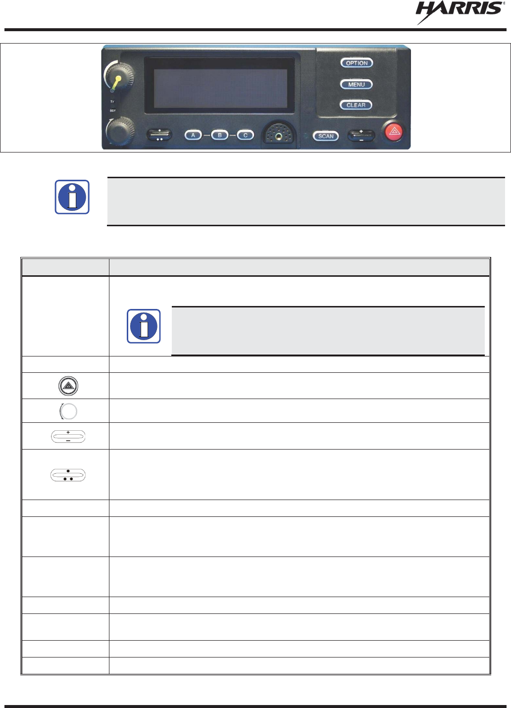
MM-012125-001, Rev. M
68
Figure 6-2: Scan Model
Button function may vary depending upon
radio programming.
Table 6-1: Front Panel Default Controls and Functions
PART FUNCTION
Power On
-
Off/Volume
Control knob
Turn knob clockwise to power on the radio and increase volume.
Turn counter
-clockwise to decrease volume and power off the radio.
The radio can be programmed to require the
entry of a PIN in order to
operate the radio. Check with your System Administrator if you forget your
PIN. As the PIN is entered, an asterisk is displayed for each digit. The actual
value is not displayed.
Mic
Connection
Connection for hand
-held, hands-free, speaker-mic, or headset.
The Emergency button declares an emergency if enabled through programming.
This rotary switch selects the systems or groups/channels, depending upon programming.
This rocker type button is used to display the current SCAN status for a group/channel and
then add or delete the group/channel from the system scan list.
The primary function of this rocker type button is to scroll through the System list or the
Group/Channel list depending upon programming.
The secondary function is to increment or decrement items within a list (phone list for
example).
OPT/OPTION
Toggle a PC programmable feature ON and OFF.
CLR/CLEAR
Exits the current operation or entry mode.
In Conventional mode, pressing this button unmutes the receiver so activity on the selected
channel can be monitored.
MENU
Primary function
-
access the menu list. This is a list of additional features that are not
available directly from the keypad.
Secondary function
- activate a selected item within a list, similar to an enter key.
SCAN
Toggles scan operation ON and OFF.
Pre-
Set buttons
A, B, C
Used to store and recall user
-selectable parameters.
SYS
Used to enter the System select mode.
GRP
Used to enter the Group select mode.
NOTE
NOTE
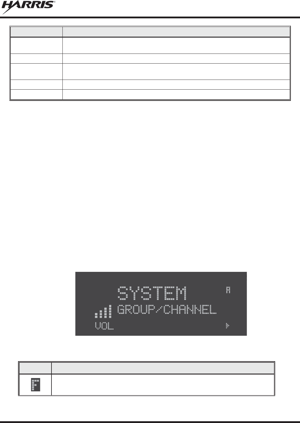
MM-012125-001, Rev. M
69
PART
FUNCTION
STS
Permits the transmis
sion of a pre-
programmed status message to an EDACS or P25 Trunked
site.
MSG
Permits the transmission of a pre
-
programmed message to an EDACS or P25 Trunked site.
PHN
Used to place telephone calls through the radio by selecting the interconnect special call
function.
DIS
Used to show the key ID and whether or not it is valid or available.
IND
Used to call an individual or make an all
-call by selecting the individual call function.
6.3 KEYPAD LOCK/UNLOCK
Scroll through the menu until “KEY LOCK” is displayed and press MENU to lock the keypad
Press MENU and OPTION to unlock the keypad.
6.4 PRESET BUTTONS
Any button on the control head can be programmed as a preset button. When programmed as a preset
button, press and hold that button for approximately three (3) seconds to store the following information
to the function of that button:
x Currently selected Priority 1, Priority 2, and Priority 3 talk groups
x Currently selected talk group
x Scan state
After changing systems, groups, or scan state, simply press the preset button to restore these settings.
Presets are saved and restored to/from non-volatile memory. Changing control heads does not recall
presets for the previous control head.
6.5 RADIO STATUS ICONS
Status icons are indicators that show the various operating characteristics of the radio.
Figure 6-3: Typical Display
Table 6-2: Icons and Descriptions
ICON
DESCRIPTION
Indicates the EDACS system is in Failsoft™ mode (if enabled through
programming).
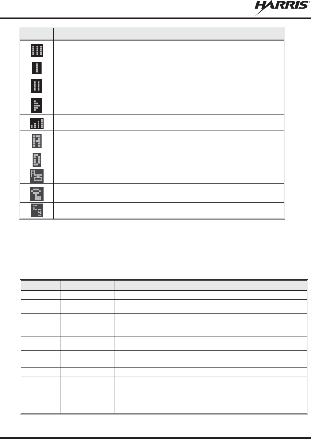
MM-012125-001, Rev. M
70
ICON
DESCRIPTION
Indicates selected group or channel is in scan list.
Indicates selected group or channel is programmed as Priority 1 in scan list.
Indicates selected group or channel is programmed as Priority 2 in scan list.
Indicates
Scan Mode enabled.
Volume bars
– indicate relative volume level.
Indicates the current channel is set up as an analog channel.
Indicates the current channel is set up as a ProVoice channel.
Indicates the current channel is set up as a
Project 25 (P25) channel.
Indicates
receiving or transmitting Encrypted Calls.
Indicates a conventional channel enabled with Channel Guard Function.
6.6 MESSAGES
During radio operation, various messages are displayed on either line 1 or line 2. Typical messages
include control channel status information, such as system busy or call denied, or messages associated
with the radio's operation, (i.e., volume adjust). These messages are described as follows:
Table 6-3: Radio Messages
MESSAGE
NAME DESCRIPTION
QUEUED
Call Queued
Indicates the system has placed the call in a request queue.
SYS BUSY
System Busy
Indicates the system is busy, no channels are currently available, the queue is full, or
an individual call is being attempted to a radio that is currently transmitting.
DENIED
Call Denied
Indicates the radio is not authorized to operate on the selected system.
CC SCAN
Control Channel Scan
Indicates the control channel is lost and the radio has entered the Control Channel
Scan mode to search for the control channel.
WA SCAN
Wide Area Scan
Indicates the control channel is lost and the radio has entered the Wide Area Scan
mode to search for a new system (if enabled through programming).
T99 ON
Type 99 Decode ON
Indicates the Type 99 Decode feature is enabled.
T99 OFF
Type 99 Decode OFF
Indicates the Type 99 Decode feature is disabled.
*RXEMER*
Receive Emergency
Indicates an emergency call is being received. This message is flashing on line 2.
*TXEMER*
Transmit Emergency
Indicates an emergency call has been transmitted. This message is flashing on line 2.
VOL=31
Volume Level
Indicates the current volume level. The volume level display ranges from OFF (silent)
to 40 (loudest).
UNKNOWN
Caller's ID Not
Received
Indicates that an individual call is being received, but the caller's ID was not received.

MM-012125-001, Rev. M
71
MESSAGE
NAME DESCRIPTION
DATA T/R
Transmit/Receive
Data
Indicates the radio is transmitting
/receiving a data call.
DATA OFF
Data OFF
Indicates the radio is in the data disabled state. Displayed on line 1.
DATA ON
Data ON
Indicates the radio has been toggled to the data enable state. Displayed for two
seconds on line 1 when toggled to enable state.
SYSC ON
System Scan
Features ON
Indicates the System Scan features are enabled.
SYSC OFF
System Scan
Features OFF
Indicates the System Scan features are disabled.
PA ON
Public Address ON
Indicates that the public address function of the radio is enabled.
PA OFF
Public Address OFF
Momentary (2 seconds) - indicates that public address function of the radio was
disabled.
ALRM ON
External Alarm
Enabled
Indicates that the external alarm function of the radio is enabled.
ALRM OFF
External Alarm
Disabled
Momentary (2 seconds) - indicates that the external alarm function of the radio was
disabled.
PVT DIS
Private Mode
Disabled
Indicates that private mode is disabled or no encryption key has been programmed for
the selected group/channel or special call.
FRCD PVT
Forced Private
Operation
Indicates that forced private operation has been pre
-programmed into radio.
NO KEY #
Encryption Key
Missing
Flashing - indicates that no encryption key or an incorrect encryption key is
programmed into the radio.
BCKL=1-6
Backlight
Indicates the display intensity and keypad backlight level.
GR
Group ID
Indicates that the call is a group call and is followed by the GID of the caller.
ID
Individual ID
Indicates the call is an individual call and the ID number of the caller, example "ID
2725."
WHC=1
Who Has Called
This display indicates the number from the Who Has Called list. Individual calls
received but not responded to are stored in a
Who Has Called
list. This list is
accessible by pressing the # key and then the INDV key after the Individual call has
timed out or the Clear button is pressed. This display is on line 2 and the LID of the
caller is displayed on the top line. Currently the list is not implemented and the display
is always WHC=1.
PHONE
Phone Call
Displayed when a phone call is received from the site. It is displayed in line 1 of the
display. Line 2 o
f the display contains
the display *INDV* when line 1 contains this
message. The radio interprets a received phone call as an individual call.
CONV FS
Conventional Failsoft
Displayed when a failure of the EDACS system occurs. All communication is in
conventional mode.
MENU
Displayed when the menu key is pressed and remains displayed in line 1 until a menu
item is selected.
SYS=1
-64
System = 1
- 64
The system number for the current base station of the system displayed in line 1. It is
displayed in line 2 of the display. Press the system key to obtain this display.
GRP=1
-64
Group = 1
- 64
The group number of the group displayed in line 2 of display. It is displayed in line 1 of
the display. Press the group key to obtain this display. There are up to 48 groups
available (i.e.
,
3 banks of 16). The maximum number of groups programmed in a radio
is determined by the personality.
INDV=1
-99
Individual = 1
- 99
Indicates which item in the individual call list is being displayed. It is displayed in line 2
of the display. The name or ID of the item in the list is displayed in line 1 of the
display.
PHN=1
-99
Phone = 1
- 99
Indicates which item in the phone list is being displayed. It is displayed in line 2 of the
display. Line 1 of the display is the last 3 characters of the list item contents.
SEL PHN
Select Phone
After pressing the PHN key, selecting an entry from the phone list by typing the entry
number displays this message on Line 1.
SEL INDV
Select Individual ID
Displayed on line 1 when an entry from the individual ID list is selected after pressing
the INDV key. The entry is a number between 1 and 32 inclusive.

MM-012125-001, Rev. M
72
MESSAGE
NAME DESCRIPTION
SYS ALL
System All Call
Displayed on line 1 to indicate a system all-call has been received.
Ggg
-v.vv
Code Group and
Revision Number
This is code group and revision number that is displayed in line 2 when the menu item
“REVISION” is selected. The ‘gg’ is the group number of the software. The first ‘v’ is
the hardware version and ‘vv’ is the revision of the software.
*PHONE*
Phone Call
Displayed when an initiated phone call is in progress. This is displayed on line 2 of the
display.
NO ENTRY
Indicates that there is no data stored in one of the programmable items in either the
phone list or individual call list. The user programmable items are items 1 through 10
in each list.
INV SYS
Invalid System
Displayed when the current system is an invalid type.
CHN=1
-99
Channel = 1
- 99
Displayed on line 1 of the display. This is a conventional channel index displayed
when the group key is pressed.
FIX LIST
Fixed List
The Priority scan list is fixed and cannot be changed using the add or delete keys.
FIXED P1
Fixed Priority 1
The Priority 1 scan channel is fixed and cannot be changed using the add or delete
keys.
EM
Emergency
Indicates an emergency has been declared by the LID that follows the display, “EM.”
An example of this is “EM 01201.”
*INDV*
Individual Call
Displayed in line 2 of the display when an individual call is in progress.
*GROUP*
Group Call
Indicates a group call is in progress and is displayed on line 1 of the display.
SPKR ON
External Speaker ON
Displayed when the external speaker is enabled.
SPKR OFF
External Speaker
OFF
Displayed when the external speaker is disabled.
BANK=1
-8
The bank of keys that are going to be loaded when the keyloader loads encryption
keys. This is only valid for radios that support VGS, VGE, or DES encryption. It is
displayed on line 2 of the display when the encryption keyloader is connected.
REGR_0x
Dynamic Regroup
Indicates which group in the dynamic regroup operation has been enabled, where “x”
is a digit of 1 to 8.
KEY LOAD
Displayed on line 1 of the display when the encryption keyloader is connected.
KEY ZERO
Displayed on line 2 of the display when the reset and option buttons are pressed
simultaneously for approximately two seconds. The encryption keys are zeroed.
SYS KEY
System Key
Displayed on line 1 of the display in the display key mode of the menu. It is followed in
the second line with a key number “KEY = <1..7>.”
GRP KEY
Group Key
Displayed on line 1 of the display in the display key mode of the menu for trunked
systems only. It is followed in the second line with a key number “KEY = <1..7>.”
KEY=1
-7
Displayed on line 2 of the display in the display key mode of the menu for
conventional systems when the “SYS KEY” or “CHN KEY” is displayed in line 1 and
for trunked systems when the “SYS KEY” or “GRP KEY” is displayed in line 1.
PRIMARY
Displayed on line 1 of the display when the primary keys are enabled.
PRS NAME
Personality Name
Displayed on line 1 of the display under the revision selection of the menu. The
personality name is displayed on line 2 at the same time.
BND SCAN
Band Scan
Only displayed if the P25T system is configured for "EnhancedCC" mode of
operation.
When the radio cannot
find a Control Channel in either the trunked
frequency set or the list of discovered adjacencies
, t
he radio is able to perform a full
spectrum frequency scan to find a new Control Channel.
REGISTER
Displayed when the radio is performing a registration/affiliation on a P25 trunking site.
6.7 ALERT TONES
The M5300 series mobile radio also provides audible alert tones or “beeps” to indicate the various
operating conditions. These alert tones can be enabled or disabled through programming.
Table 6-4: Alert Tones
NAME
TONE
DESCRIPTION
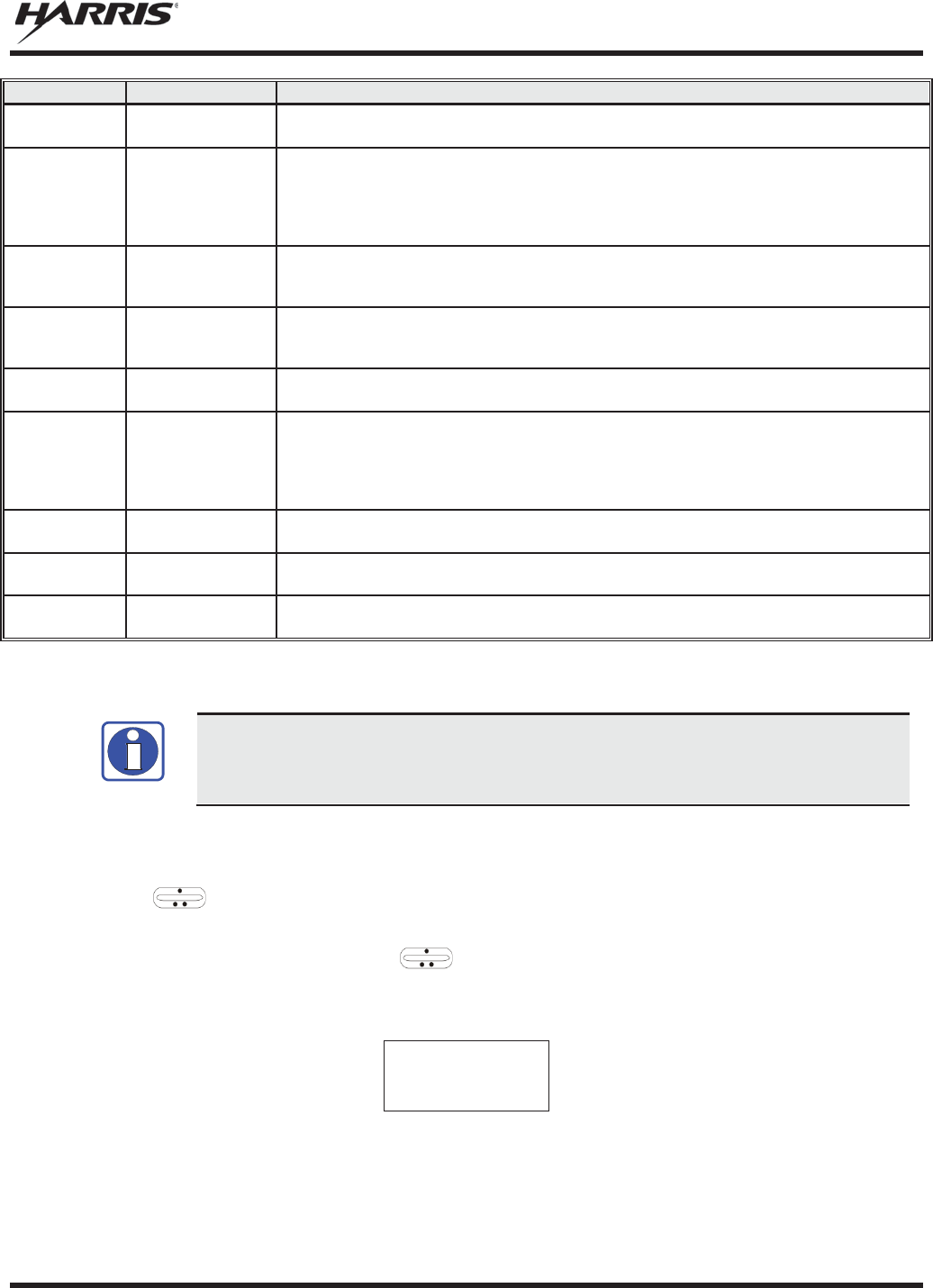
MM-012125-001, Rev. M
73
NAME
TONE
DESCRIPTION
Call Originate
One short mid-
pitched tone
Sounds after keying the radio (Push-To-Talk button is pressed). Indicates the radio has
been assigned a working channel.
Autokey
One
mid-pitch
ed
tone
After being placed in a queue or releasing the PTT button prior to a working channel
assignment, the site calls the radio when a channel becomes available. At this point,
the radio automatically keys the transmitter (autokey) for a short period to
hold the
channel. The radio sounds a mid
-
pitched tone when it is clear to talk. Immediately
press the PTT button to keep the assigned channel.
Call Queued
One
high-
pitched
tone
Sounds after pressing the PTT button indicating the system has placed the call request
in the queue. The receiving unit(s) also sound(s) the tone to indicate they will receive a
call shortly.
System Busy
Three low
-
pitched
tones.
Sounds if the radio is keyed when the system is busy, if no channels are available for
sending the message, if the call queue is full, or if an individual call is being attempted to
a radio that is transmitting.
Call Denied
One low-pitched
tone
Indicates the radio is not authorized on the system that has been selected.
Carrier
Control Timer
Five short high-
pitched warning
tones followed by
a long low
-
pitched tone
Sounds if the programmed time for continuous transmission is exceeded.
The
transmitter shut
s
down shortly after the alert, interrupting communications. Release and
re
-key the PTT button to maintain communications. This resets
the carrier control timer
and turn
s the transmitter back on.
Key Press
Alert
One
short tone
Indicates a key has been pressed. A short low-pitched tone indicates no action was
taken because the key is not active in the current mode.
Page
(P25T Only)
Three high-
pitched tones
In P25 trunked mode, if the receiving radio accepts a page, both the receiving and
transmitting radios emit three high-pitched tones.
Out of Range
One low pitched
tone
Indicates the radio is in Wide Area Scan. The radio periodically beeps when in Wide
Area Scan.
6.8 MENU
To directly access a
menu
, press the corresponding button on the control head. For
example, press the
SYS button to enter the System select mode.
Button configuration
may vary depending
on radio programming.
The order and specific number of menu items available is configurable through programming. Upon radio
power up, the menu item at the beginning of the menu list is always displayed first. Subsequent access to
the menu function returns the last menu item shown in the display. To enter the menu mode, press
MENU. and CLR are used during the selection process. The radio continues to receive and
transmit normally while in the menu function.
A new item is displayed by using the ramp control to scroll through the list in increasing and
decreasing order. The displayed menu item is made active by pressing MENU.
After entering the menu, the following generic display format appears.
M E N U
Y Y Y Y Y Y Y Y
Line 1 indicates the radio is in the menu. Line 2 indicates the menu item (YYYYYYYY) that is to be
viewed or changed (some menu items provide radio information and do not have changeable parameters).
NOTE
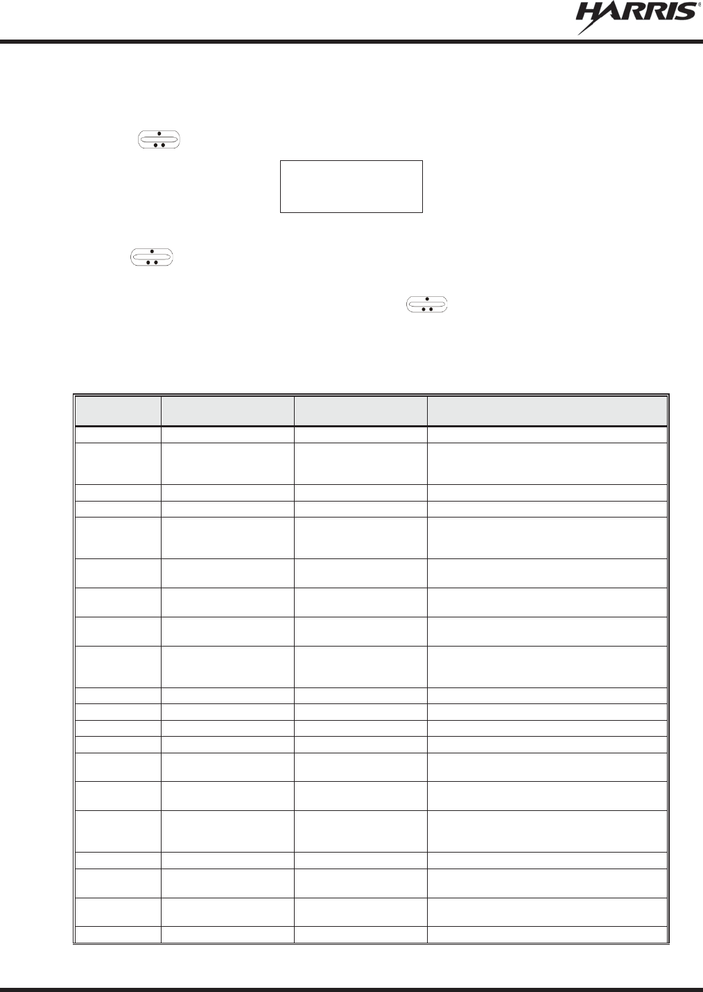
MM-012125-001, Rev. M
74
An example of the menu item selection process and menu item parameter change is detailed below for the
brightness menu item.
1. Press MENU to enter the menu mode.
2. Press the ramp control until the display shows:
M E N U
BACKLGHT
3. Press MENU.
4. Use the ramp control to increase or decrease backlight brightness. Once the desired setting is
reached, press MENU to store the value and return to the normal display.
5. For menu items that display radio information, use to scroll through a list of informational
displays.
The menu items are listed in Table 6-5.
Table 6-5: Menu Item Information
FEATURE
DISPLAY
PARAMETER
SETTINGS
COMMENT
Backlight Adjust
Menu Item: BACKLGHT
Sets the backlight level.
Radio Revision
Information
Menu item:
REVISION
Informational displays
only; no user selectable
settings.
Selects the information display to view.
Phone Call
Menu item: PHONE
Allows access to the Phone Call Feature.
Individual Call
Menu Item: INDV
Allows access to the Individual Call Feature.
External Alarm
Menu Item:
E
XTALARM
ON, OFF
EXTALARM replaces the system name on the
display as long as the external alarm feature is
enabled.
Public
Address
Menu item: PUB ADDR
ON, OFF
Public Address is toggled ON and OFF.
External
Speaker
Menu item: EXT SPKR
ON, OFF
External Spe
aker is toggled ON and OFF.
Encryption Key
Loading
Menu item: KEYLOAD
Up to 8 banks of 7 keys
Enables the radio to accept the loading of
encryption keys.
Display Current
Encryption
Key(s)
Menu item:
DISP KEY
Displays current encryption key number.
Scan
Menu item: SCAN
ON, OFF
Toggles scan function ON or OFF.
Private Mode
Menu Item: PRIVATE
ON, OFF
Toggles private function ON or OFF.
Scan Add
Menu item: SCAN ADD
S, 2 or 1
Adds group or channel to scan list.
Scan Delete
Menu item: SCAN DEL
Deletes group or channel from scan list.
Scan
Add/Delete
Menu item: SCAN A/D
Toggle sequence
S, 2, 1
Changes present group or channel to next scan
choice in scan list.
Last Scanned
Channel Recall
Menu Item: SCAN ADD
Changes the selected channel to the last
scanned channel.
Home group or
channel
selection
Menu item:
HOME
Changes to the group or channel defined for
Home function.
System select
Menu item: SYS
Displays the system selected.
System and
group selection
Menu item:
S/G 1 – S/G 16
Changes to the System & Group/Channel
programmed for SYSGRP 1-16.
Mute
Menu item:
MUTE ON, OFF
Toggles the mute function ON or OFF to control
the audio output from the selected radio.
No Data
Menu item: NO DATA
ON, OFF
Toggles data feature ON or OFF.
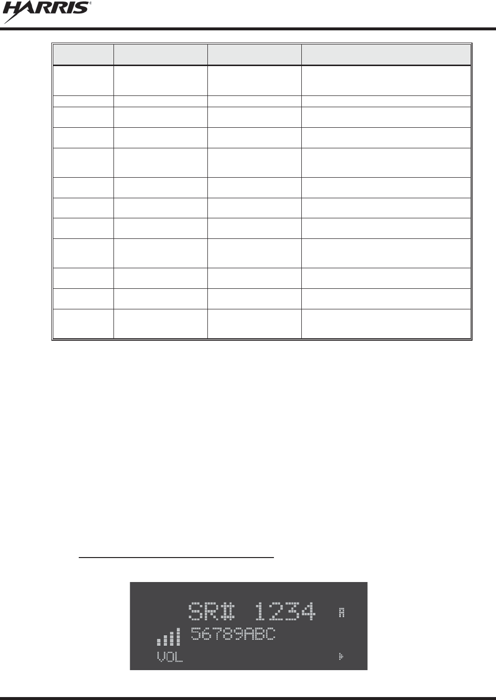
MM-012125-001, Rev. M
75
FEATURE
DISPLAY
PARAMETER
SETTINGS
COMMENT
EDACS
Conventional
Priority 1 Scan
Menu item:
ECP1
SCN
ON, OFF
Toggles this feature ON or OFF.
Group selection
Menu item: GRP
Displays the group selected.
Status Condition
Menu item:
STATUS
0-9 = (n)umber of pre-
programmed status
Transmits the pre-programmed status
message.
Message
Condition
Menu item: MESSAGE
0-9 = (n)umber of pre-
programmed messages
Transmits the pre
-programmed message.
Feature
Encryption
Display
Menu Item: FEATURES
Informational displays
only; no user selectable
settings
Indicates current features programmed into the
radio as well as certain information required to
add features to the radio.
System Scan
Enable
Menu Item: SYS SCAN
ON, OFF
System Scan features like ProScan are toggled
ON and OFF.
Talkaround
feature
Menu item:
TALK ON, OFF
Toggles Talkaround ON or OFF (transmit
frequency changed to receive frequency).
Type 99 Decode
Enable
Menu Item:
T99 EN ON, OFF
Type 99 Decode is toggled ON and OFF.
Display
GPS
info
rmation
Menu Item:
GPS
Displays GPS Status (On/Off), Latitude,
Longitude, Speed/Dir
ection, and time.
See
Section 6.38 for more information.
Select Mixed
System/Zone
Menu Item:
ZONE
Select a Mixed System Zone.
Display Caller
ID
Menu Item:
CALL ID
Displays the Radio IDs or alias names for the
last 10 received calls.
View/Modify
Custom Scan
List
Menu Item: CUSTSCAN
Allows you to view and edit a Custom Scan list.
See Section
6.23.7 for more information.
6.9 FEATURE ENCRYPTION DISPLAY
Feature Encryption Display is available through the menu function and, if programmed, appears in the
menu as “FEATURES.” This data indicates current features programmed into the radio as well as
information required to add features to the radio.
Once the feature has been accessed, all normal menu functions work. The user can scroll up or down
through all of the entries.
Feature Encryption Display provides the ability to view, in the order displayed, the following:
x Serial number ROM data - serial number of the ROM
x Feature encryption data stream - used to enable features
x Number Fields - defines limits
x Features enabled - displays bit fields of enabled features
6.9.1 Serial Number ROM (12 Hex Digits)
Example:
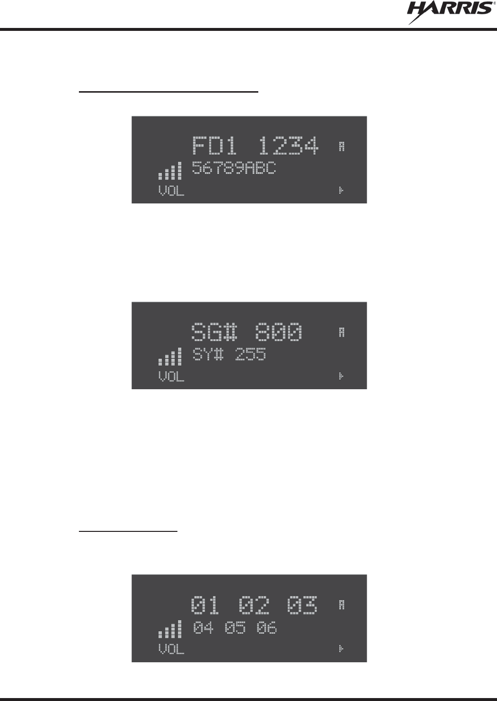
MM-012125-001, Rev. M
76
To enable a feature in a radio, call Harris and they will ask for the ROM serial number. The serial number
shown here is for example only.
6.9.2 Feature Encryption Data Stream
Example:
These data streams define the features the user has enabled in his radio and are required by Harris to
enable other features. The data streams shown here are for example only. There are three displays: FD1,
FD2, and FD3. All three are required.
Number Fields
Example:
These number fields show the set limits of the user's radio as:
x SG# XXX - Maximum number of system/groups combination available
x SY# XXX - Maximum trunked system limit
x CH# XXX - Maximum number of conventional channels available
The user needs to know the limits of his radio before attempting to enable other features. The numbers
shown here are for example only.
6.9.3 Features Enabled
These numbers indicate which features are enabled.
Example:

MM-012125-001, Rev. M
77
Table 6-6 lists possible features available in the user's radio.
Table 6-6: Available Feature Numbers
FEATURE
NUMBER
POSSIBLE FEATURES
STANDARD OR
OPTIONAL
01
Conventional Priority Scan
Standard
04
Group Scan (EDACS and P25 Trunked)
Standard
05
Priority System Scan (EDACS and P25 Trunked)
Optional
06
W
Ascan/ProScan (EDACS and P25 Trunked)
Optional
07
Dynamic Regroup
Standard
08
EDACS Emergenc
y Standard
09
Type 99 Encode
Standard
10
Conventional Emergency
Standard
14
DES Encryption
Optional
16
Mobile Data
Optional
17
Status/Message (EDACS and P25 Trunked)
Optional
21
EDACS Security Key (ESK)
Optional
22
ProFile™ (EDACS and P25 Trunked)
Optional
23
Narrowband
Standard
29
ProVoice™
Optional
32
FIPS
-140-2 Optional
33
P25 Common Air Interface
Optional
34
Direct Frequency Entry
Optional
38
Radio TextLink
Optional

MM-012125-001, Rev. M
78
6.10 VOICE ANNUNCIATION
When enabled via programming, the Voice Annunciation feature provides audible feedback for various
radio operations. The radio can be programmed to play an audio message for any or all of the following.
This message can be a pre-recorded (canned) message or a user-recorded message.
x Channel changes
x System changes
x Encryption On/Off
x Noise Cancellation On/Off
x Scan On/Off
x Talkaround On/Off
For more information on configuring the radio for Voice Annunciation, refer to the Voice Annunciation
Feature manual, 14221-7200-6110.
6.11 SYSTEM/GROUP/CHANNEL SELECTION
The M5300 SYSTEM/GROUP/CHANNEL knob and the ramp control are programmable for
maximum flexibility. If the SYSTEM/GROUP/CHANNEL knob is assigned to select groups or channels,
then the ramp control is assigned to select systems. If the SYSTEM/GROUP/CHANNEL knob is
assigned to select systems, then the ramp control is assigned to select groups or channels. System,
group, and channel selection is the primary function for these controls.
Systems or groups can also be selected by pressing SYS or GRP and using the ramp control to
scroll through available options.
6.11.1 System Selection
Several methods, some of which depend on programming, can be used to select a new system. These
procedures are presumed to be starting from the normal receive display.
METHOD 1:
If system selection is programmed to the SYSTEM/GROUP/CHANNEL knob, select a
system by turning the SYSTEM/GROUP/CHANNEL knob to the desired system
position. The display registers the new system name on line 1. If the wrap option is OFF
and the knob is moved to a position greater than the number of programmed systems, the
highest programmed system remains selected.
METHOD 2:
If system selection is programmed as the primary function of the
ramp control,
select a system by pressing up
or down to scroll through the system list. The display
registers the new system name on line 1.
METHOD 3:
Press
SYS to enter the system select mode and use the
ramp control to scroll
through the systems.
6.11.2 Group and Channel Selection
Several methods, some of which depend on programming, can be used to select a new group or channel.
These procedures assume starting from the normal receive display.

MM-012125-001, Rev. M
79
METHOD 1:
If group selection is programmed to the SYSTEM/GROUP/CHANNEL knob, select a
group by turning the SYSTEM/GROUP/CHANNEL knob to the desired group. The
display registers the new group name on line 2. If the wrap option is OFF and the knob
is moved to a position greater than the number of programmed groups, the highest
programmed group remains selected.
METHOD 2:
If group selection is programmed as the primary function of the
ramp control,
select a group by pressing up or down, to scroll through the group list. The display
registers the new group name on line 2.
METHOD 3:
Press
GRP to enter the group select mode and use the ramp control to
scroll
through different groups.
METHOD 4:
Press the key programmed for Channel Entry (must be programmed to a button using
RPM R10B or later). Enter the channel number. Entering a number greater than the
maximum number of entries will select the last channel. Channel changes made with
the knob are made with respect to the manually entered channel.
6.12 LAST SYSTEM/GROUP/CHANNEL RECALL
This feature, enabled through programming, allows the user to recall the last selected system/group after
an emergency or home function or system/group key function. For example, if the Home button (pre-
programmed) is pressed, the radio goes to the designated Home system/group or channel. If the Home
button is pressed again, the radio returns to the previous system/group or channel. At this time, the user
can toggle between the Home system/group or channel and the previous system/group or channel. The
operation is the same for the SG1-SG16 buttons.
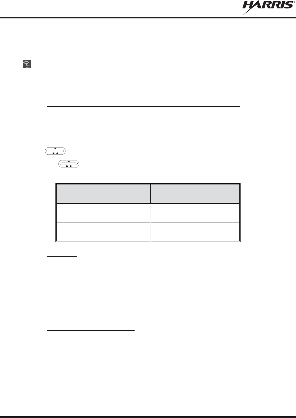
MM-012125-001, Rev. M
80
6.13 ENCRYPTION
The M5300 mobile radio supports AES and DES encryption. When operating on a group or channel
programmed for encryption, all transmissions are private and the radio receives clear and private signals.
is displayed when encryption is enabled. If the selected group or channel is programmed for auto-
select capability, the mode may be toggled between encrypted and unencrypted by pressing the MENU
key, and then selecting the PRIVATE menu option. Radios programmed for forced encryption do not
allow a change of the transmit mode.
6.13.1 Displaying the Currently Used Cryptographic Key Number
To display the cryptographic key currently in use for either the system encryption key (for special call
such as individual, phone, all, agency or fleet) or the group/channel key (for group or conventional calls),
perform the following procedure:
1. Press the MENU button.
2. Use to select DISP KEY. Then press the MENU button.
3. Then use to toggle between displaying the system key or the group/channel key.
Table 6-7: Current Cryptographic Key Display
ENCRYPTION KEY
DISPLAYED
MESSAGE DISPLAYED
System
"SYS KEY"
"KEY = 1"
Group/Channel
"GRP KEY"/"CHN KEY"
"KEY = 2"/KEY = 2"
6.13.2 Key Zero
All cryptographic keys can be zeroed (erased from radio memory) by pressing and holding the
CLR/CLEAR button, and while still pressing this button, press and hold the OPT/OPTION button. Press
both buttons for 2 seconds. A series of warning beeps begins at the start of this 2-second period and then
switches to a solid tone after the keys have been zeroed. The display indicates KEY ZERO.
If the cryptographic key(s) are zeroed, one or more keys must be transferred from the Key Loader into the
radio before private communications can continue. Refer to Key Manager TQS3416 Administration and
Software Release Notes for further information.
6.13.3 Receive an Encrypted Call
When receiving, the radio automatically switches between clear or encrypted operation. If the
transmission being received is an encrypted transmission, it is decrypted, the receiver unsquelches, and
the message is heard in the speaker. The selected group or channel must be programmed for encryption
and the correct cryptographic key must be loaded into the radio for this to occur.

MM-012125-001, Rev. M
81
6.13.4 Transmit an Encrypted Call
1. Select the desired group or channel.
2. Enable encryption by pressing the MENU button and then selecting the PRIVATE menu option, or
press the button on the control head that has been programmed for PRIVATE.
x If the last state of the radio was encryption enabled, then encryption is enabled on power up. In
addition, encryption is enabled if forced operation has been programmed in the radio
x If a group or channel is not programmed for encryption, PVT DIS is displayed if an attempt is
made to enable encryption. It is not possible to operate on this group/channel in encrypted mode.
x If the radio is programmed for forced encryption mode, FRCD PVT is displayed if an attempt is
made to disable encryption. It is not possible to transmit on this group/channel in clear mode.
x If the radio does not have the correct encryption key loaded, NO KEY # is displayed and the call
does not transmit.
3. Continue with standard transmission procedures. An access tone is heard when the PTT button is
pressed.
6.13.5 Emergencies on Encrypted Group
The radio can be programmed to allow emergency calls to be transmitted in the clear when the radio does
not have the key, or has an invalid key for the encrypted group in emergency.
6.14 MACRO KEY OPERATION
Macro key operation permits the user to accomplish a series of keystrokes with a single "macro"
keystroke. Up to ten (10) macro keys can be defined, each capable of executing up to twenty (20)
keystrokes, to any pushbutton input (i.e., keypad keys, buttons, etc.). Each macro key can be pre-
programmed to activate when pressed or when released. A macro key can also be pre-programmed to
change the keystroke sequence the next time the macro key is activated. For detail operation and
assignment of macro keys, contact your system administrator.
6.15 RECEIVE A CALL
1. Turn the radio on by rotating the POWER ON-OFF/VOLUME knob clockwise (out of detent). A
short alert signal (if enabled through programming) indicates the radio is ready to use.
2. The display shows the last selected or the power up (depending on programming) system and
group/channel names. If the radio is unable to obtain a control channel, line 2 shows CC SCAN.
3. Adjust the volume to the desired level.
4. Select the desired system and group/channel.
5. The radio is now ready to receive calls.
6. When the radio receives a call, it unmutes on the assigned working channel and the BSY indicator
comes on. Line 1 shows GR followed by the logical ID number (if received) of the unit sending the
message, or the associated name if the ID number is found in the individual call list.
6.16 TRANSMIT A CALL
1. Turn the radio on and set the POWER ON-OFF/VOLUME knob to the desired volume level. Select
the desired system and group/channel.
MM-012125-001, Rev. M
82
2. Ensure that conventional channels are not busy by pressing the CLR button to briefly disable any
channel decoding and unmute the receiver, or observe the unlit BSY indicator. If the Channel Busy
Lockout feature is programmed for the selected channel, the radio does not transmit when the channel
is busy.
3. Press and hold the PTT button.
4. When the working channel is assigned, the TX and BSY indicators are turned ON and a short beep is
sounded indicating communication can begin.
If two or more tones
(or a high-pitched tone) are heard,
the system may be busy and
the call request has been placed in queue or the request has been denied for some
reason. Refer t
o the Section 6.7 for more details.
5. Hold the microphone approximately 2 inches from the mouth and speak in a normal voice.
6. Release the PTT button when the transmission is complete and listen for a reply.
6.17 CONVENTIONAL FAILSOFT (EDACS)
In the unlikely event of a failure of the EDACS system, communications can take place in conventional
failsoft mode. The radio is automatically directed to a communications channel set up for this purpose.
During this mode of operation, the control unit displays CONV FS in the alphanumeric display. An
increase in activity on the channel during conventional failsoft operation may be noticed, so be careful not
to transmit until the channel is clear.
Operation during conventional failsoft is the same as operation on a conventional system, except that it is
not possible to select a communications channel, or use emergency and special call. When trunking is
restored, the radio is automatically returned to normal operation.
Emergency and Special Call are not operational during conventional failsoft. In
addition, the
GRP control does not operate.
6.18 EMERGENCY OPERATION
The radio's emergency behavior varies depending on programming. When an emergency is declared,
scanning stops and only restarts after the emergency is cleared.
6.18.1 Receive an Emergency Call
When receiving an emergency call from the selected group and system, an alert beep sounds and the BSY
indicator illuminates. The message *RXEMER* flashes in the display on line 2 until the emergency
condition is cleared. Follow standard emergency procedures.
6.18.2 Declare an Emergency
To send an emergency call to the selected system and group (or on an optionally pre-programmed
emergency group), proceed as follows:
1. Press and hold the red emergency button for approximately one second. (This time is programmable
and could be longer or shorter. Check with the system administrator.) The radio transmits an
emergency call request with the radio ID until an emergency channel assignment is received.
NOTE
NOTE

MM-012125-001, Rev. M
83
2. When the working channel assignment is received, the radio sounds a single beep (Autokey alert
tone) indicating it is ready for voice transmission. *TXEMER* flashes on line 2 in the display until
the emergency is cleared.
3. Press PTT and speak into the microphone in a normal voice.
4. Release PTT when the transmission is complete and listen for a reply.
5. The emergency can be cleared by pressing and holding the CLR button followed by pressing the red
emergency button then releasing both buttons.

MM-012125-001, Rev. M
84
6.19 MIXED SYSTEM ZONES
A Zone is a grouping of analog conventional channels, P25 conventional channels, and/or P25T or P25C
talkgroups. Mixed System Zones are defined in RPM and can be comprised of any combination of
channels/groups from multiple systems as long as the system definitions share the same WACN/System
ID. If a Mixed System Zone is not configured in RPM, it will not appear on the radio. Up to 50 Mixed
System Zones can be defined.
To select a Mixed System Zone:
1. Press MENU.
2. Scroll through menu and select ZONE.
3. Select the desired Mixed System Zone.
Alternately, the System/Group/Channel knob or a button on the radio can be programmed to scroll
through available Mixed System Zones.
When scan is enabled on a system in a Mixed System Zone, the radio continues to display the zone name
or system name per the current radio mode (system/zone). When toggling scan ON/OFF, there is no
change one line 1 of the radio display. If it is showing system name, it continues to show system name; if
it is showing zone name, it continues to show the zone name during scanning.
6.20 CALLER ID
This feature allows you to view the caller ID or alias for up to the last 10 received calls. Received calls
include Group, Announcement, Phone, Patch, SimulSelect, Agency, Fleet, and MDC.
1. Press MENU and scroll through menu to select CALL ID. Alternately, a button can be programmed
to access the CALL ID list.
2. Scroll through available entries. The most recent call is displayed at the top of the list. “NO
ENTRY” is displayed if there are no entries.
3. Caller ID or “NO ENTRY” is displayed for 10 seconds. Press the Clear button to exit the Caller ID
list.
The most recent call is displayed at the top of the list. The Caller ID list is cleared when power is cycled
on the radio.
6.21 STEALTH MODE
Press the button programmed for Stealth Mode operation to toggle Stealth Mode on or off. During Stealth
Mode, all buttons are disabled except PTT, the button programmed for Stealth operation, Emergency, and
Nuisance delete. The radio will receive and transmit when Stealth Mode is enabled.
The radio can be configured to disable any or all of the following during Stealth Mode:
x LCD display
x LED
x Backlight
x Side/alert tones

MM-012125-001, Rev. M
85
Stealth Mode can be configured to persist through a power cycle.
6.22 SYSTEM SCAN OPERATION (EDACS AND P25 TRUNKED)
The radio can be programmed with the following System Scan features. These features are automatically
enabled upon radio power up. A key or menu option is also defined to allow the System Scan features to
be toggled during radio operation. The System Scan state is maintained through system changes but
defaults to ON at power up.
6.22.1 Wide Area System Scan (WA Scan)
The M5300 Series mobile radio can be programmed for wide area system scan operation for multi-site
applications. Upon the loss of the currently selected system's control channel, radios can be programmed
to automatically scan the control channels of other systems. If a new control channel is found, the radio
switches to the new system and sounds an alert tone. The amount of time before the radio enters Control
Channel Scan after losing the control channel is configurable in RPM.
6.22.2 ProScan™
The radio can be programmed for ProScan™ system scan operation for multi-site applications depending
on the version of radio flash code. ProScan provides the radio with the ability to select a new system for
the radio to communicate on, when the selected system drops below a predefined level. This is
accomplished by enabling each radio to analyze the signal quality of its current control channel and
compare it with the signal quality of the control channel for each site in its adjacency scan list. The signal
quality metric used for the ProScan algorithm is based on a combination of both Received Signal Strength
Indicator (RSSI) and Control Channel Verification (CCV) measurements. When the selected system’s
signal quality level degrades below a pre-programmed level, the radio begins to look for a better control
channel. Once a control channel that exceeds the pre-programmed parameters is found, the radio changes
to the new system and emits a tone. If the control channel is completely lost, the radio enters Wide Area
System Scanning and searches the programmed adjacent systems until a suitable control channel is found.
6.22.3 Priority System Scan
The radio can also be programmed for Priority System Scan. (To ensure that this feature operates
correctly, the control channel of the priority system must be located on channel one unless you are using
the ProScan algorithm.) The priority system is the desired or preferred system. While receiving the
control channel of the selected system, the radio periodically leaves the selected system and searches for
the control channel of the priority system at a programmable rate. The programmable rate is defined by
the value in the Priority Scan Time control, (unless the ProScan algorithm is enabled as explained below).
This priority scan timer is reset each time the PTT button is pressed or when a call is received. If the
priority system control channel is found, or meets the predefined ProScan criteria, the radio automatically
switches to the priority system.
6.22.4 When Wide Area System Scan is Enabled
If the radio cannot find the control channel of the selected system and begins Wide Area System Scan, the
radio only scans for the priority system control channel if the priority system is in the WA Scan list.
6.22.5 When ProScan Is Enabled
The radio monitors the priority system and switches to the priority system if the priority system meets the
criteria defined in the “ProScan Options” dialog box. If ProScan is enabled, the rate at which the radio
scans for the priority system is defined by the System Sample Time control.

MM-012125-001, Rev. M
86
6.22.6 Menu Selection
Press MENU and then use the ramp control to scroll through the selections until SYS SCAN is
displayed. Then press MENU to toggle the System Scan state. The SYSC ON or SYSC OFF display
message is displayed for two seconds to show the new state.
6.22.7 Pre-Programmed Keypad Key
Press the pre-programmed key and the SYSC ON or SYSC OFF display message is displayed for two
seconds to show the new state.
6.23 SCAN OPERATION
Only groups or channels that are part of the radio's scan list are scanned. Groups/channels are added to the
scan list on a per system basis through programming, the radio keypad, or both, dependent upon
programming. This scan list can be changed by the user from the keypad, unless programmed otherwise.
Each system's scan list is retained in memory when the radio is turned off. The M5300 Series mobile
radio can also be programmed to provide Trunked Priority Group Scan capability, which operates similar
to priority scan in Conventional mode.
The following is a description of programmable scan features that should be helpful in understanding the
scan operation of the radio:
Scan Hang Time - the delay time the radio waits before resuming scan after the push-to-talk is released
or after the carrier has dropped a channel.
TX Select - the group the radio transmits on while scanning. The radio is programmed to transmit on
either the scanned group or the selected group.
Scan List (privileges) - this feature allows or prohibits scan list changes by the user.
P1 Programming - priority group programming is accomplished by one (and only one) of three methods:
x From the keypad, where the Priority programming is not fixed and does not follow the selected
channel.
x Priority 1 group programming follows the selected channel.
x Priority 1 group programming is fixed during PC programming and cannot be changed by the user.
P1 Always Scan - determines if the Priority 1 Group is always scanned, regardless of the scan state set by
the user.
6.23.1 Add Groups or Channels to a Scan List
1. With scan operation turned off, select the desired group channel to add to the selected scan list.
2. Press (+) or (-) with to display the current priority status of the group on line 1 for a time-out
period.
3. While the status is displayed, press (+) with to add the group/channel to the scan list. is
displayed.
4. Press (+) with a second time to set the group/channel to Priority 2. is displayed.
5. Press (+) with a third time to set the group/channel to Priority 1. is displayed in column 1,
line 1.
MM-012125-001, Rev. M
87
The priority level selection sequence only advances the group to the next higher priority level and stops at
priority level 1. To select a lower priority level, the group/channel must be deleted from the scan list and
then added back to the scan list. Each new group/channel added to the scan list starts at the lowest
priority. If the Priority 1 and Priority 2 group/channel are already set and a new group/channel is assigned
as Priority 1 or Priority 2, the previously assigned group/channel changes to non-priority scanning.
6.23.2 Delete Groups or Channels from a Scan List
1. With scan operation turned off, select the desired group/channel to delete from the selected scan list.
2. Press (+) or (-) with . The current scan status of the group/channel is displayed for a time-out
period.
3. Press (-) with to delete the group from the scan list. , or turns off. Any group/channel
that is not in a scan list shows a “blank” when it is the selected group/channel.
6.23.3 Nuisance Delete
A group/channel can also be deleted from the scan list, if it is not the currently selected group/channel, by
pressing (-) with during scan operation while the radio is displaying the unwanted group/channel.
The group/channel is deleted from the scan list in the same manner as if using the steps above. Deletions
performed in this manner do not remain deleted if the radio is turned off and back on.
6.23.4 Turn Scan On
1. Toggle scan operation by pressing SCAN. The SCAN indicator turns on when the radio is scanning.
Scanning stop
s while the microphone is off-hook if the hoo
kswitch feature is enabled
through programming.
2. When a group on the scan list receives a channel assignment, the radio unmutes on the assigned
channel, the BSY indicator comes on and the received scan group is displayed.
x The radio continues scanning if a new group/channel is selected when scan is on.
x Pressing the PTT button when scan is on causes the radio to transmit on the displayed
group/channel or on the currently selected group depending on programming.
x Pressing up with when scan is on causes the radio to recall the scanned group/channel that
was last received. This group/channel is recalled for a period equal to the scan hang time.
6.23.5 Priority Group/Channel Scanning
When scan is enabled and the Priority 1 and Priority 2 groups/channels have been identified, the radio
listens to calls on those groups/channels and the selected group/channel. While receiving a scanned call,
the radio continues to monitor the selected Priority 1 and Priority 2 group/channel and drops the call if the
selected group/channel or other higher priority call becomes active. During a Priority 2 call, the radio
continues to monitor for a Priority 1 group call.
The radio monitors for Agency and Fleet calls that correspond to the Agency and Fleet associated with
the Priority 1 and Priority 2 groups. Priority Agency and Fleet calls are indicated by displaying AGENCY
or FLEET on the System line of the display and associated Priority 1 or Priority 2 group on the Group
line of the display.
NOTE
MM-012125-001, Rev. M
88
6.23.6 Turn Scan Off
Turn scan operation off by pressing SCAN. The radio resumes operation on the selected group/channel.
6.23.7 Mixed Zone Scan
The Mixed Zone Scan (MZS) feature gives the user the capability to scan based on a custom scan list that
is assigned at the system level. The Custom Scan (CS) list can contain System and Channel/Group
configurations across P25 Trunk, P25 Conventional, and Analog Systems. When a Custom Scan List is
defined on a P25T system, the radio can scan P25T, P25C and Analog systems. When defined on a P25C
or Analog system, the radio only scans conventional channels. MZS also gives the user the capability to
scan beyond the selected system group set.
x P25T Scan
When a custom scan list is assigned to a P25T system, the user has the ability to scan P25T, P25C,
and Analog groups/channels. All P25T systems must have the same WACN, System ID, and Unit ID
to be added to the custom scan list.
x P25C and Analog Scan
When a custom scan lists is assigned to a P25C or Analog System, the user has the ability to scan
P25C and Analog channels. P25T systems are ignored.
6.23.7.1 Custom Scan List Selection
The Custom Scan List is assigned at the System level. Scanning protocols (Custom Scan, System Scan,
and Conventional Priority Scan) are mutually exclusive. Once a custom scan list is assigned to a system,
when you enable scan, you are scanning the channel/groups defined in the custom scan list. A Custom
Scan List can be assigned to a system through RPM only.
The radio supports up to 10 Custom Scan lists, with up to 50 channels/groups in each.
6.23.7.2 View Custom Scan Lists
Scan must be off to view a Custom Scan List.
1. From the radio menu, select CUSTSCAN.
2. Select the desired group/channel from the Custom Scan list. Options available for each
channel/group include:
x View the channel’s/group’s scan priority.
x Delete the channel/group from the scan list.
x Nuisance delete the channel/group.
3. Press the Option button to back up one display; press the Clear button to return to the home screen.
NOTE
MM-012125-001, Rev. M
89
6.23.7.3 Edit Custom Scan Lists
Scan must be off to edit a Custom Scan List.
1. From the radio menu, select CUSTSCAN.
2. Select EDIT LST.
3. Select the desired system from the list.
4. Select the desired channel group. Scroll through available options:
x Add the channel/group to the scan list.
x Change the channel’s/group’s scan priority.
x Delete the channel/group from the scan list.
x Nuisance delete the channel/group.
5. Press the Option button to back up one display; press the Clear button to return to the home screen.
6.24 INDIVIDUAL CALLS (EDACS AND P25 MODES)
6.24.1 Receive and Respond to an Individual Call
When the radio receives an individual call, it unmutes on the assigned working channel and turns on the
BSY indicator. Line 1 shows “ID” followed by the logical ID number of the radio sending the message,
or the associated name if the ID number is found in the individual call list. The individual call indicator
displays *INDV* on line 2. The radio can be programmed to ring when an individual call is received. If
enabled, the ring begins five seconds after the caller unkeys and continues until the PTT button, the CLR
button, or IND is pressed.
Hookswitch functions the same as
CLR key in I-Call
, phone call, and menu modes.
If a response is made to the call prior to the programmed call-back time-out, the call is directed to the
originating unit. If a response is not made before the call-back time-out, the radio returns to normal
receive mode, but * WHC * is displayed. If the caller's ID is not received, UNKNOWN displays for the
duration of the call and there is no call-back hang time.
To respond after the call-back time-out, press the IND key. The radio's display shows the callers ID on the
first line and WHCI=1 on the second line. Pressing the PTT button at this point initiates an individual call
back to the original caller. (If the last call was a group call, the display shows WHCG=1. Pressing the
PTT button places the call as an individual call.)
The radio stores the IDs of the last 10 callers in the Calls Received List as shown. Individual calls are
stored in the top half of the list (1-10) and group calls are stored in the bottom half of the list (1-10). The
most recent call is stored in position 1, the second most recent call is stored in position 2, etc.
NOTE
NOTE
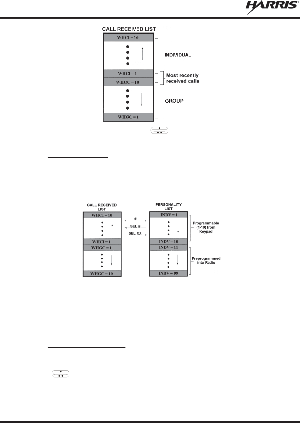
MM-012125-001, Rev. M
90
To access the list, press the IND key twice. Use to scroll through the list. Press the MENU key to
display the time elapsed since the call was received.
6.24.2 Call Storage Lists
There are two lists available for call storage in the radio, the calls received list (1-10) and the personality
list (1-99 as defined by the user). When the individual call mode is entered by pressing IND, the calls
received list is available. The user can toggle to the personality list by selecting any key other than DIS or
toggle between the two lists by pressing the IND key. If wrap is enabled, the calls received list wraps on
itself and not into the other list.
The saved call list shows all ten storage locations. If no calls have been received, the saved call list is
empty and the pre-stored list is available upon entering the individual call mode.
When in the saved call list, pressing MENU toggles the time stamp ON and OFF. The time stamp
indicates how long ago the call was received. The display indicates this information as HH:MM:SS where
HH = hours, MM = minutes and SS = seconds.
When in the pre-stored list, pressing MENU toggles the Logical IDentification (LID) ON and OFF.
6.24.3 Send an Individual Call
The following procedures describe how to initiate and complete an individual call.
1. To select a previously stored individual, select the I-Call mode from the menu or press IND followed
by the ramp control to scroll through the list of stored individuals. While in the individual call
list, the MENU key toggles the display between the call name and the unit ID number. If the
individual is not stored in this list but the individual’s unit ID is known, it can be entered directly
from the keypad.
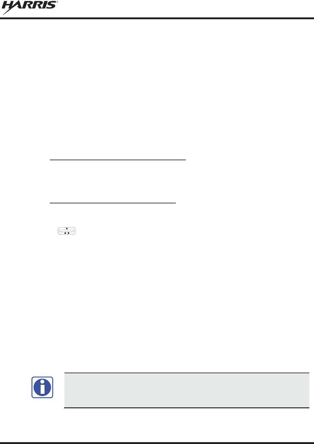
MM-012125-001, Rev. M
91
2. Press the PTT button. The radio performs the necessary signaling to obtain a communication channel.
When the signaling is complete and the radio is clear to transmit, the TX indicator turns ON and the
channel access tone sounds. Line 1 shows the called individual's name if found in the list of stored
individuals or ID followed by the logical ID number of the unit being called. The message *INDV*
displays on line 2. Proceed with the message.
6.25 SCAT™ OPERATION
A SCAT (Single Channel Autonomous Trunking) System operates with the same set of features as a
standard EDACS system. The only significant user change relates to the BSY indicator. Since only one
channel, operating as both control and working channel, exists in a SCAT System, the BSY indicator is
ON when the SCAT channel is in the working channel mode. When the transmission on the channel is
completed, the indicator turns OFF and indicates the return of SCAT control channel signaling.
6.26 TELEPHONE INTERCONNECT CALLS (EDACS AND P25)
6.26.1 Receive a Telephone Interconnect Call
Receiving a telephone interconnect call is identical to receiving an individual call. See the DTMF
Overdial Operation section if access to services requiring "over-dial" is needed. Overdial operations are
available for any special call whether it is an individual call or a telephone interconnect call.
6.26.2 Send a Telephone Interconnect Call
Use the following procedures to initiate and complete a Telephone Interconnect call:
1. To select a previously stored phone number, select phone call mode from the menu, press PHN and
use the ramp control to scroll through the list of stored phone numbers. While in the phone
call list, the MENU key toggles the display between the phone call name and the phone call number.
If the phone number is not stored in this list but the phone number is known, it can be entered directly
from the keypad. If necessary, a pause can be entered by pressing and holding 0-9, (*), or (#) until an
underscore appears in the display.
2. Press and release the PTT button; the radio performs the necessary signaling to obtain a
communication channel. When the signaling is complete and the radio is clear to transmit, TX
indicator turns on and the channel access tone sounds. Line 1 shows the accompanying name if
selected from the list of stored numbers or the phone number if entered directly. The message
*PHONE* is displayed on line 2. The radio then automatically transmits the programmed number
stored in the special call queue.
3. Telephone ringing is heard. When someone answers the phone, press the PTT button and speak into
the microphone. Release the PTT button to listen to the caller. Unsuccessful interconnect signaling
returns the radio to the normal receive mode and the number remains displayed until the special call is
cleared by pressing the CLR button or the time-out expires or another group or system is selected.
4. To terminate the call, momentarily press the CLR button.
The M5300 Series mobile radio is capable of half-duplex conversation only. The
caller’s message can only be sent if the PTT button is pressed (the radio is
transmitting) and the caller can only be heard by the person being called when the PTT
is released (the radio is receiving).
NOTE

MM-012125-001, Rev. M
92
6.26.3 DTMF Overdial/Conventional Mode Telephone Interconnect
Once the radio has established a connection to the public telephone system, it may be necessary to "over-
dial" more digits to access banking services, answering machines, credit card calls or other types of
systems that require DTMF (Dual-Tone Multi-Frequency) access digits. Overdial operation can also be
used to initiate a telephone interconnect call via DTMF signaling if a dial tone has already been accessed
on the system. This is the method that is used for making a telephone interconnect call while operating in
the conventional mode but also functions in trunked mode if a dial tone is directly accessible. Telephone
numbers and other number sequences for overdialing can be stored in the phone list when programming
the radio or stored by the operator in the first ten phone list entries. These numbers are accessed by
pressing PHN.
The following steps are required to dial these numbers:
1. Follow the procedure in Section 6.26.2 to establish a connection to the telephone system or consult
the system administrator for the procedure to access a dial tone on the trunked or conventional
system.
2. Overdial numbers are transmitted using either method as follows:
METHOD 1:
Press and hold PTT while entering the overdial number sequence from the keypad.
This method sends DTMF tones during individual, telephone interconnect, trunked
group, or conventional channel calls. Anytime the PTT button is pressed and held,
the keypad is enabled for DTMF entry.
METHOD 2:
Press
PHN to access
a stored number from the phone list or to directly enter the
overdial digits. Press PTT to send the overdial sequence once. If the number needs to
be transmitted again it must be selected or entered again (this prevents unwanted
numbers from being sent the next time the PTT button is pressed during the call).
This overdial select/entry mode remains active until the call is dropped, cleared, or MENU is pressed. The
overdial select/entry mode can be re-entered if the call is still active by pressing PHN.
6.26.4 Programmable Entries
Individual call ID numbers, telephone numbers and other number sequences for overdialing are stored in
the special call lists when programming the radio. The first ten entry locations of these lists can be
changed by the radio operator. The keypad is used when adding, changing, and storing numbers in these
entry locations.
Use the following procedure to store a number in one of the first ten entries of a special call list:
1. Press IND or PHN to enter the individual call list or the phone call list.
2. Scroll through the list using the ramp control until one of the first ten (10) entries is reached.
NO ENTRY is displayed if the location is empty.
3. Enter the desired number. If necessary, a pause can be entered by pressing and holding 0-9, (*), or (#)
until an underscore appears in the display. The individual call list entries accept up to 5 digits. The
phone call list entries accept a combination of up to 31 digits and pauses.
4. Press and hold MENU until the display changes indicating that the number has been stored.
5. Repeat the steps above if the number stored in an entry location needs to be changed.
MM-012125-001, Rev. M
93
6.27 MOBILE DATA
The M5300 Series mobile radios permit either voice or data calls to be transmitted or received. The radio
can handle only one type of call at a time; however, selection of either data or voice is transparent to the
operator.
The mobile radios can be connected to Mobile Data Terminals (MDT) or to a host computer. Any RS-232
compatible device that supports the Radio Data Interface (RDI) protocol (Version 1.91 or greater) can be
connected to the mobile radio. Support for MDTs or host computers is a programmable option per radio.
Additionally, radios programmed for host computers can also be programmed for data only operation (no
voice calls transmitted or received).
Turn power to the radio OFF before connecting or disconnecting any cables, including
the data cable. Also, turn power to the radio OFF when docking or undocking a
connected laptop computer. Failure to turn
the power OFF can damage the radio,
requiring service by a Harris approved service center.
6.27.1 Displays
The following is displayed on the control unit during the various states of data mode of operation.
DATA T/R
Displayed on bottom line of display when the radio is transmitting/receiving a data call.
DATA OFF
Displayed on top line of display when the radio is in the data disabled state.
DATA ON
Displayed for two seconds on top line of display when the radio is toggled to the data
enabled state.
6.27.2 DATA OFF Operation
The radio can be placed in the data disabled state by any of the following methods. When the data state is
disabled, the control unit displays "DATA OFF" on the top line. An ongoing data call is allowed to
complete except when an emergency is declared.
x Removing the microphone from the hookswitch (hookswitch option must be enabled by pre-
programming).
x Declaring an emergency (not to be used unless an actual emergency condition exists). Alert tone
sounds.
x Pressing the OPT/OPTION (pre-programmed). Alert tone sounds.
x Selecting the function using the MENU button (pre-programmed).
6.27.3 DATA ON Operation
The data state is enabled by one of the following (depending on how it was disabled). “DATA ON” is
displayed top line of display for 2 seconds then the display returns to normal.
x Replacing the microphone into the hookswitch (going on-hook). Only valid if the “DATA OFF”
operation was entered by removing the microphone from the hookswitch (going off-hook).
x Clearing an emergency, but valid only if an emergency caused “DATA OFF” operation.
NOTE

MM-012125-001, Rev. M
94
6.27.4 Exiting Data Calls
Under normal conditions, the radio enters the scan lockout mode and returns to the control channel after
completion of a data call (transmit or receive). If, during a data call, one of the following conditions
occurs, the data call is immediately terminated and the radio performs the desired function:
x The PTT is activated.
x The PTT is in Public Address Mode.
x An emergency is declared by pressing the pre-programmed emergency button.
x A group or system change is made.
6.27.5 Scan Lockout Mode
Following the transmission or reception of a data call, if scan is enabled, scanning stops temporarily
(duration pre-programmed). During this time the scan LED flashes to indicate that scan is enabled but
temporarily suspended. This mode is normally exited when the pre-programmed time expires; however,
the following actions terminate the scan lockout mode before the timeout is completed:
x The CLR/CLEAR button is pressed.
x PTT is pressed.
x A group or system change is made.
x Enter phone call mode.
x Enter individual call mode.
x A new emergency assignment has been received.
x PTT is pressed in Public Address Mode.
x An emergency is declared or cleared.
x Microphone is removed from hookswitch (off-hook).
x Receiving an individual or phone call.
x Receiving an Agency, Fleet, or System All Call.
x Pressing the SCAN button to turn scan ON or OFF.
6.27.6 Data Lockout Mode
The data lockout mode is a pre-programmed mode when the radio does not respond to any data channel
assignments and prevents receive data calls from interrupting voice calls. Transmit data calls are still
initiated when needed by the operator. After a pre-programmed time, the radio responds to receive data
calls; however, the following conditions clear the data lockout mode:
x The CLR/CLEAR button is pressed.
x Transmitting a data call.
x Changing a system.
x An emergency is declared.
x Pressing PTT while in Public Address Mode.
x Turning scan ON with the SCAN button.

MM-012125-001, Rev. M
95
6.28 STATUS/MESSAGE OPERATION (EDACS AND P25 TRUNKED)
Status and message operation is possible with either the Scan or System version of the M5300 Series
mobile radio unit. The following procedure is applicable for the System version. For operation with the
Scan version, the four primary keycaps must be reconfigured and pre-programmed for status/message
operation.
6.28.1 Status Operation
Status operation permits the transmission of a pre-programmed status condition to the EDACS or P25
Trunked site.
To send a status condition, press the STS button and then press one of the number buttons (0-9) to select
the pre-programmed status. If no status has been programmed for the selected number button, the radio
displays NO ENTRY and the radio sounds a low tone. A valid selection permits the status text to appear
in the display for a pre-programmed time. After the time-out expires or the MENU button has been
pressed (the MENU button overrides the time-out period), the status is selected and is transmitted to the
site or stored in the radio memory where it can be polled by the site at a future time. If the site receives
the status properly, when transmitted or polled by the site, a high-pitched tone sounds and the keylight
associated with that status remains lit. If the site does not receive the status properly, a low-pitched tone
sounds and the keylight associated with the status blinks.
If an incorrect status is selected or the incorrect number button is pressed, the status can be changed
during the pre-programmed time-out period by pressing another number button. The status selection can
also be cancelled by pressing the CLR button prior to the time-out period.
To view the currently selected status after it has been transmitted, press the STS button. If the status was
not sent successfully to the site, the text associated with the status flashes in the display.
The radio can also be pre-programmed to re-designate the keypad buttons for ST0 thru ST9 to send
status condition. In this configuration the radio status operation operates as previously described except
the STS button is not required. The keylight associated with ST0 thru ST9 indicates which status is
selected.
6.28.2 Message Operation
Message operation permits the transmission of a pre-programmed message text to an EDACS or P25
Trunked site.
To send a message, press the MSG button and then press one of the number buttons (0-9) to select the
pre-programmed message text. If no message text has been programmed for the selected number button,
the radio displays NO ENTRY and a low-pitched tone sounds. A valid selection permits the message text
to appear in the display for a pre-programmed time. After the time-out expires or the MENU button has
been pressed (the MENU button overrides the time-out period), the message text is selected and is
transmitted to the site. If the site receives the message properly when transmitted, a high pitched tone
sounds and the MSG keylight remains lit. If the site does not receive the message properly, a low-pitched
tone sounds and the MSG keylight blinks.
If an incorrect message text is selected or the incorrect number button is pressed, the message text can be
changed during the pre-programmed time-out period by pressing another number button. The message
text selection can also be cancelled by pressing the CLR button prior to the time-out period.
To view the currently selected message text after it has been transmitted, press the MSG button and then
the CLR button prior to the time-out period. If the message text was not sent successfully to the site, the
text associated with the message flashes in the display.
MM-012125-001, Rev. M
96
6.29 EDACS CONVENTIONAL P1 SCAN
This feature permits the radio user to scan a pre-programmed conventional system and channel as a
Priority 1 (P1) channel while the radio is selected for EDACS trunked system. If activity is detected on
the conventional P1 channel, the radio unmutes and remains on this conventional channel for the
programmable hang time. The radio must be pre-programmed to designate a button for scan ON/OFF
operation.
6.30 DYNAMIC REGROUP OPERATION (EDACS)
Dynamic regroup operation permits multiple talk groups (up to eight) to be added to a radio via the
Communications Systems Director (CSD). The radio must be pre-programmed to respond to regrouping.
Dynamic regrouping is not activated in a radio until an activation message is sent by the system manager.
Each radio that receives and acknowledges regrouping instructions is successfully regrouped.
Pressing and holding CLEAR/CLR for 2.5 seconds toggles the user into and out of the dynamic regroup
group set. A double beep sounds for entry or exit. The display indicates REGR_0x where "x" is a digit of
1 to 8 indicating the group when dynamic regroup has been enabled by the user. If the radio is in dynamic
regroup and the user selects a group that has not been regrouped, the display shows NO ENTRY. The
radio is prevented from transmitting and receiving calls in this condition except for scanned groups.
If the pre-programmed group set on the currently selected system contains an EMER/HOME group and
the radio is in dynamic regroup, the radio exits dynamic regroup and declares the emergency on the
HOME group. If no EMER/HOME group is present, the radio declares the emergency on the currently
selected dynamic regroup group.
6.31 PAGE (P25 TRUNKED ONLY)
Page sends a PING message to a radio and functions similar to Individual Call. The following procedures
describe how to initiate and complete a Page.
1. To select a previously stored individual, select PAGE from the menu, followed by the ramp
control to scroll through the list of stored individuals. While in the individual call list, the MENU key
toggles the display between the call name and the unit ID number. On System model radios, the
individual’s unit ID can also be entered directly from the keypad.
2. Press the PTT button; the radio performs the necessary signaling on the control channel. On the
calling radio, line 1 shows the called individual's name if found in the list of stored individuals or ID
followed by the logical ID number of the unit being called. If the receiving radio receives the Page
and responds, both radios emits three high-pitched tones. The receiving radio also displays PAGE and
the ID of the calling radio.
6.32 SQUELCH ADJUST (CONVENTIONAL)
In the conventional mode of operation, the squelch can be re-adjusted in the MENU or from a front panel
key on the keypad that has been pre-programmed. A default value of 9, or any user level between 1 and
16, can be selected using programming software. The user can change this setting either of two ways from
the front panel keys.
A value of 16 requires a strong signal to open squelch, a value of 2 requires a very weak
signal to open squelch, and a value of 1 is open squelch.
NOTE
MM-012125-001, Rev. M
97
When the squelch adjust feature is activated, Channel Guard, T99 decode, and Scan are
disabled. When the squelch adjust feature is exited, Channel Guard, T99 decode, and
Scan are restored to the
ir previous states.
6.32.1 Menu Selection
1. Press the MENU key and then use the ramp control to scroll through the selections until
SQUELCH is displayed. Then press MENU again.
2. The display shows SQLCH=xx, where "xx" is the value between 1 and 16.
3. Use the ramp control to scroll through the values. Then press the MENU key to save the new
value after the display time-out (2 seconds). The displayed value is selected and saved.
4. If the MENU or CLR key is pressed before the time-out, the menu feature exits and the squelch level
is not updated. The original value is restored.
6.32.2 Pre-Programmed Keypad Key
1. Press the pre-programmed key and the display indicates SQLCH=xx, where "xx" is the value
between 1 and 16.
2. Use the ramp control to scroll through the values. Then press MENU to save the new value
or wait for the display time-out (2 seconds). The displayed value is selected and saved.
3. If the CLR key is pressed before the time-out, the squelch level is not updated and the original value
is restored.
6.33 TYPE 99 DECODE (ANALOG CONVENTIONAL)
If the Type 99 Decode Option has been pre-programmed, individual Selective Calling is possible. The
radio can now decode individual, group, or supergroup paging calls. Two sets of Type 99 paging codes
must be pre-programmed into the radio. When the radio decodes an appropriate Type 99 code sequence,
an alert tone and visual indicator is provided to the user. The receiver then operates as a noise squelched
unit until Type 99 is reset. Type 99 decode continues to operate during this noise squelched period. The
appropriate Type 99 alert tone sounds again if it detects a valid two-tone sequence.
Type 99 operation can be reset manually or automatically (pre-programmed). Manual reset is achieved by
briefly pressing CLR, if programmed. Automatic reset, if enabled, occurs after a 30 second interval
following the most recent decode of a Type 99 tone sequence. Hookswitch (pre-programmed) can also
enable or disable Type 99 decode. The pre-programmed key light blinks when Type 99 is disabled by the
hookswitch.
Type 99 decode continues to be active while the radio's CLR button is pressed. This allows the user to
monitor calls and still be alerted when a call is directed to the user. While the user continues to press
CLR, the user hears both calls and all Type 99 tone signals. If CLR is pressed for longer than two (2)
seconds, Type 99 decode is either disabled or re-enabled depending upon its present state.
To check the Type 99 enable status, press the Scan Add/Delete ramp control. The current status of
Type 99 decode is displayed for a time-out period.
If a Horn Alert Option is installed and enabled with the Type 99 Decode Option, the radio can beep the
vehicle horn when a Type 99 call is received. This option permits alerting persons out of the vehicle when
a call is received.
NOTE

MM-012125-001, Rev. M
98
Type 99 is automatically disabled when Scan is enabled.
6.33.1 Menu Selection
Press MENU and then use the ramp control to scroll through the selections until T99 ENAB is
displayed. Then press MENU to toggle the Type 99 decode state. The T99 ON or T99 OFF display
message is displayed for two seconds to show the new state.
6.33.2 Pre-Programmed Keypad Key
Press the pre-programmed key and the T99 ON or T99 OFF display message is displayed for two
seconds to show the new state.
6.34 TALK-AROUND (ANALOG CONVENTIONAL)
Talk-around provides short range, line of sight communications.
1. Make sure the radio is ON and then select the desired conventional system and channel.
2. Press the pre-programmed button to toggle talk-around on.
3. Ensure that the channel is not busy by pressing CLR/CLEAR to briefly disable any channel decoding
and unmute the receiver or observe the unlit BSY indicator. If the Channel Busy Lockout feature is
programmed for the selected channel, the radio does not transmit when the channel is busy.
4. Press and hold the PTT button. The TX indicator illuminates and a short beep sounds (if pre-
programmed) indicating that communication can begin.
5. Release the PTT button when the transmission is complete and listen for a reply.
6. When the communication is completed, press the pre-programmed button to toggle the talk-around
function off.
Or
1. Make sure the radio is ON and then select the desired conventional system and channel.
2. Select TALKARND from the menu to toggle talk-around on and off.
6.35 CONTROL AND STATUS SERVICE
The M5300 supports Control and Status services. These services allow the computer application to
monitor and control a radio. The Control and Status Services can be used from a locally-connected
Mobile Data Terminal (MDT) or a network MDT. In some cases, the radio can support both MDTs
simultaneously. However, priority is given to the local MDT.
The Radio Status Service allows an MDT or Fixed End System (FES) to receive real-time status updates
from a radio. An MDT sends Host Attach/Detach messages to the radio as UDP datagrams destined for
the UDP Service Address and Service UDP Port of the radio. All responses and asynchronous reports are
returned to the address and port of the requesting host. Refer to the Control and Status Services Technical
Reference Guide, 14221-1700-5000, for more information on this feature.
6.36 AUDIO PLAYBACK
Every call received by the radio is recorded in internal memory, overwriting the last recorded call. When
NOTE
MM-012125-001, Rev. M
99
the PLAYBACK key is pressed, the last recording is replayed and any future recordings are stopped.
Pressing PLAYBACK again repeats the same recorded call. Pressing and holding the PLAYBACK key
until the tone sounds erases the recording and starts the recording of incoming calls again. If a call is
received while the recorded call is playing, the recorded call continues to play, rather than the received
audio. However, if a call is received and the recorded call is played back in close succession, received
audio could mute call playback. This feature requires RPM R8A and later, and ECP R15A and later.
The PLAYBACK function must be programmed to a button on the control head or hand-
held controller via RPM.
Front mount M5300 radios do not support audio playback.
6.37 RADIO TEXTLINK OPERATION
Radio TextLink provides a simple means of exchanging pre-defined, or “canned,” text messages. This
section describes how to send messages if the Radio TextLink feature is enabled.
6.37.1 Send TextLink Messages
1. Press MENU to access the menu.
2. Scroll through menu until SND MAIL is displayed. Press MENU to select.
3. Scroll through the pre-defined messages and press MENU to select to select the desired message.
4. Scroll through the list of available destination IDs and select the desired ID with MENU.
6.37.2 Receive TextLink Messages
Received Messages are listed in the order in which they are received (newest at the top). All messages
include the user LID along with the date and time stored/displayed. The mailbox can hold 16 messages at
a time. If a new Message arrives after the limit is reached, the new message overwrites the oldest
message.
When a new Radio TextLink message is received, RCV TXT is displayed on the top line of the display
and the incoming message scrolls underneath.
To view all received messages:
1. Press MENU to access the menu.
2. Scroll through menu until RD MAIL is displayed. Press MENU to select.
3. Scroll through the list of received messages.
4. Selecting a received message with the MENU key will bring up a reply to sender option.
6.37.3 Delete TextLink Messages:
Select DEL MAIL with the MENU key to delete ALL messages in the inbox.
NOTE
NOTE

MM-012125-001, Rev. M
100
6.37.4 To view the current time:
Select TIME with the MENU key to retrieve the current date and time.
6.38 VIEW GPS INFORMATION
If the M5300 is equipped with the optional GPS receiver module, you can view your position and satellite
information via the GPS Menu. GPS requires an unobstructed view of the sky and the signal is greatly
diminished inside buildings, tunnels, heavily forested areas, etc. GPS may not work at all under some
conditions, especially in metal enclosures or buildings.
1. Press MENU to access the menu.
2. Scroll through menu until GPS is displayed and press MENU to select.
3. Scroll through available information screens.

MM-012125-001, Rev. M
101
7. BASIC TROUBLESHOOTING
If the radio is not operating properly, check Table 7-1 for likely causes. For additional assistance, contact
a qualified service technician.
Table 7-1: Basic Troubleshooting
SYMPTOM CAUSE SOLUTION
Radio will not turn on.
No power.
Test the connection to the vehicle power supply.
Radio will not turn off.
If in multiple control head configuration,
one of the attached control heads is still
powered up.
Power off all control heads.
Radio will not register or
does not receive
provisioning data.
Bad l
ogon credentials.
Check logon and password.
No audio.
Speaker volume is muted.
Increase the volume level.
Poor audio.
Transmitting or receiving in a poor
coverage area or subject to interference.
Check network connectivity and move to a better
coverage a
rea if possible.
Report the area without
coverage to an authorized network technician.
No network connectivity
icon in display.
Radio is out-of-range or cannot connect
with the OpenSky network.
Base station network connection has
failed.
Return to coverage area if possible and wait for
condition to clear
.
Use single
-site trunking or switch to an alternate
channel.
Radio will not transmit.
Radio may be out of coverage area or may
be overheated.
Return to coverage area if possible. If overheated, let
radio
cool before retrying transmission.
Report this
failure to an authorized technician.
Radio will not transmit
(transmit indicator does not
flash).
Radio may be experiencing low voltage.
The M5300 will cease to transmit if the voltage drops
below 8.5 volts
. Have the battery checked by an
authorized technician.
Radio powers off for no
apparent reason.
Radio may be experiencing very low
voltage.
The M5300 automatically powers down when voltage
drops below +5.0 volts. Have the battery checked by
an authorized technician.
“Warning: No MRU”
Message.
Radio control head is unable to
communicate with mobile radio unit (radio
transceiver).
Have the radio connections checked by an authorized
technician.
C
ontrol head randomly
changes display.
In multiple control head configurations,
another user is operating the radio from
another control head.
None
.
Screen displays:
UNAUTH3
The radio network ID has not been added
to the network.
Contact system administrator.
Screen displays:
NOAUTHV
Radio authentication of the VNIC
failed.
Contact system administrator.
Screen displays:
NOAUTHM
VNIC authentication of the radio failed.
Contact system administrator.
Screen displays:
NOSUPRT
The voice authentication security policy is
set to only allow authenticated users.
Contact sys
tem administrator.

MM-012125-001, Rev. M
102
8. CUSTOMER SERVICE
8.1 CUSTOMER CARE
If any part of the system equipment is damaged on arrival, contact the shipper to conduct an inspection
and prepare a damage report. Save the shipping container and all packing materials until the inspection
and the damage report are completed. In addition, contact the Customer Care center to make
arrangements for replacement equipment. Do not return any part of the shipment until you receive
detailed instructions from a Harris representative.
Contact the Customer Care center at http://www.pspc.harris.com/CustomerService or:
North America:
Phone Number: 1-800-368-3277
Fax Number: 1-321-409-4393
E-mail: PSPC_CustomerFocus@harris.com
International:
Phone Number: 1-434-455-6403
Fax Number: 1-321-409-4394
E-mail: PSPC_InternationalCustomerFocus@harris.com
8.2 TECHNICAL ASSISTANCE
The Technical Assistance Center's (TAC) resources are available to help with overall system operation,
maintenance, upgrades and product support. TAC is the point of contact when answers are needed to
technical questions.
Product specialists, with detailed knowledge of product operation, maintenance and repair provide
technical support via a toll-free (in North America) telephone number. Support is also available through
mail, fax and e-mail.
For more information about technical assistance services, contact your sales representative, or call the
Technical Assistance Center at:
North America: 1-800-528-7711
International: 1-434-385-2400
Fax: 1-434-455-6712
E-mail: PSPC_tac@harris.com
8.3 WARRANTY
Please register this product within 10 days of purchase. Registration validates the warranty coverage, and
enables Harris to contact you in case of any safety notifications issued for this product.
Registration can be made on-line at the Customer Care center webpage:
http://www.pspc.harris.com/Service/Customerservice.aspx.
While on the webpage, please review the applicable battery and/or product warranty literature.

MM-012125-001, Rev. M
103
APPENDIX A CONFIGURING ENCRYPTION
Refer to the following documentation for advanced programming and setup instructions:
x Harris OTAR Overview Manual - MM-008069-001
x Network Key Manager Installation and Configuration Manual - MM-008070-001
x Harris UAS Key Management Application Manual - MM-008068-001
x Harris Key Manager Key Admin Overview and Operation Manual - MM1000019423
x Harris Key Manager Key Loader Overview and Operation Manual - MM1000019424
x Motorola® Key Variable Loader (KVL) Device User's Guide
A.1 CREATE KEYS USING HARRIS KEY ADMIN
Harris Key Admin is part of the Harris Key Manager and is used by the Crypto Officer (CO). The CO
creates a Master Set of keys from which a Distribution Set is produced. Using the Key Admin software,
the CO can save keys into Distribution key files for technicians to use in radios.
1. Select Start Æ
Æ
Programs
Æ
Harris Key Manager
Æ
Harris Key Admin.
2. Select New Master Set, Open, or Import from Security Device. Refer to the Key Admin online
help for more information on creating keys.
3. When finished, create a Distribution Key File. A Distribution Key File is used with the Key Loader to
load key sets into the radio and cannot be edited. Refer to the Key Admin online help for more
information on creating the Distribution Key File.
A.2 LOAD ENCRYPTION KEYS
A.2.1 Load UKEKS with Key Loader and RPM (for OTAR-Enabled Systems)
UKEKs are loaded into Harris OTAR radios using the Key Loader application. Key Loader is a part of
Key Manager.
To load encryption keys:
1. Obtain the UKEK file and Storage Location Number (SLN) Binding Report information from the
Crypto Officer (CO).
Both AES and DES UKEKs can be contained within the same UKEK file.
2. If not already on, power-up the PC that has RPM and the Key Loader applications installed on it, and
start Windows®.
3. Connect the radio to the PC using a serial cable (14002-0143-01).
4. Enter into the Harris Keyload Mode (HKL).
a. Press the radio’s MENU button.
b. Scroll through the menu to select the KEYLOAD option and press the MENU button to
activate.
NOTE

MM-012125-001, Rev. M
104
c. Scroll through and select the HKL option and press the MENU button. The radio can now accept
keys from the Harris Keyloader.
5. Load the UKEK file from the Crypto Officer onto the PC.
6. Run the RPM application and setup the radio’s Mission Plan according the SLN Binding Report
information.
7. Setup the talk groups and the SLN mappings (Talk Group ID to SLN). This includes mapping SLNs
to the “System” keys (PSTN, All Call, etc.).
8. Select Options Æ
Æ
P25 OTAR Options and set the following:
a. The OTAR Message Number Period (MNP) as defined by the System Administrator.
b. The radio’s Individual RSI (from the SLN Bindings Report).
c. The KMF’s RSI (from the SLN Bindings Report).
9. Program the Mission Plan to the radio.
10. Run the Key Loader application.
11. Open the UKEK file loaded in step 5.
12. Select the Target Device type and click the Load button.
13. The Key Loader reads the target device’s identifying information, retrieves a UKEK of the proper
algorithm type from the UKEK file, and downloads the UKEK to the target device at the proper SLN
and keyset with the proper key ID.
14. Click the Finish button to exit the Key Loader application. New UKEKs have are loaded and the
radio is now ready to accept TEKs via OTAR with the trunked radio network.
A.2.2 Load Keys Using Harris Key Loader
Harris Key Loader is part of Harris Key Manager and can be used by the Crypto Officer or Technician to
load the keys into the radio.
Refer to the Harris Key Loader online help if additional information is required when performing this
procedure.
1. Connect the radio to the PC using a serial cable.
2. Power on the radio, if not already.
3. Select Start
Æ
Programs
Æ
Harris Key Manager
Æ
Harris Key Loader.
4. At the Key Loader Welcome screen, click Next.
5. Select Load a Distribution Set into one or more devices.
6. Click Next.
7. Browse to the Key File and enter the password.
8. Click Next to validate the password and continue. If the password is incorrect, the screen will display
an error message.
9. Select communication port from the drop-down and click Next.
10. Select the serial port that you have connected to the radio.
11. Enter into Harris Keyload Mode (HKL).
MM-012125-001, Rev. M
105
a. Press the radio’s MENU button.
b. Scroll through the menu to select the KEYLOAD option and press the MENU button to activate.
c. Scroll through and select the HKL option and press the MENU button. The radio can now accept
keys from the Harris Keyloader.
12. Select Radio from the drop-down and click Load.
13. Click Finish.
A.2.3 Power on the Motorola KVL Device
1. Connect KVL Device to the radio using cable 14002-0143-01.
Once the
KVL Device
is connected, a keyset is established whether the keys are
loaded or not. You will need to zeroize to bring the
radio to a fully zeroized state.
2. Press the radio’s MENU button.
3. Scroll through the menu to select the KEYLOAD option and press the MENU button to activate.
4. Scroll through and select the KVL option and press the MENU button. The radio can now accept
keys from the KVL Device.
A.2.4 Load Keys Using Motorola KVL Device
Type 3 Digital Encryption Standard Output Feedback (DES-OFB) and Advanced Encryption Standard,
256-bit (AES-256), encryption methods are supported. The Type 3 Encryption keys are loaded via a
Motorola Device using Telecommunications Industry Association (TIA)/Project 25 (P25) key fill device
protocol. Make sure that valid keys have been created and stored in the KVL Device before proceeding.
A.3 PROTECTED KEYS
The Protected Keys feature transfers P25 Voice Keys, from Harris Key Loader to the radio, that have
been wrapped (AES) or encrypted (DES) with Key Protection Keys (KPKs). KPKs are nothing more than
unprotected Key Encryption Keys (KEKs). The KPKs need to be loaded into the radio before the
Protected Keys are loaded. Once loaded into the radio, the KPKs will be used to unwrap (AES) or decrypt
(DES) the Protected Keys.
The radio must be placed into the key loading mode (see Section A.2.2) in order to accept the KPKs and
P25 Voice Keys.
NOTE

MM-012125-001, Rev. M
106
Harris Corporation, Public Safety and Professional Communications (PSPC) Business continually evaluates its
technical publications for completeness, technical accuracy, and organization. You can assist in this process by
submitting your comments and suggestions to the following:
Harris Corporation fax your comments to: 1-434-455-6851
PSPC Business or
Technical Publications e-mail us at: PSPC_TechPubs@harris.com
221 Jefferson Ridge Parkway
Lynchburg, VA 24501

Public Safety and Professional Communications | www.pspc.harris.com
221 Jefferson Ridge Parkway | Lynchburg, VA USA 24501 | 1-800-528-
7711

Product Safety Manual
MM-014763-001
Rev. N, Mar/15
This manual contains important safety information regarding specific absorption rate
(SAR) and RF exposure limits included in United States and international standards.
Read the
information in this manual before operating your radio.
M5300, M7300, and XG-75M
Series Mobile Radios
(S
Rea
the
his m
SAR)
d
l contains i
nd RF exposure
information in th
mpor
limits
is ma
tant safety i
included
nua
nfor

MM-014763-001, Rev. N
2
MANUAL REVISION HISTORY
REV.
DATE
REASON FOR CHANGE
L
Apr
/13
Revised regulatory information
and related publications. Removed installation
information (see publication MM
-014763-400).
M
Oct
/13
Added support for XG
-75M.
N
Mar/15
Revised to include model
RU-144750-061 (Rev. L) and French translations.
Harris Corporation, Public Safety and Professional Communications (PSPC) Business, continually evaluates its technical
publications for completeness, technical accuracy, and organization. You can assist in this process by submitting your
comments and suggestions to the following:
Harris Corporation fax your comments to: 1-434-455-6851
PSPC Business or
Technical Publications e-mail us at: PSPC_TechPubs@harris.com
221 Jefferson Ridge Parkway
Lynchburg, VA 24501 ACKNOWLEDGEMENT
This device is made under license under one or more of the following US patents: 4,590,473; 4,636,791; 5,148,482;
5,185,796; 5,271,017; 5,377,229; 4,716,407; 4,972,460; 5,502,767; 5,146,497; 5,164,986; 5,185,795; 5,226,084; 5,247,579;
5,491,772; 5,517,511; 5,630,011; 5,649,050; 5,701,390; 5,715,365; 5,754,974; 5,826,222; 5,870,405; 6,161,089; and
6,199,037 B1. DVSI claims certain rights, including patent rights under aforementioned U.S. patents, and under other U.S.
and foreign patents and patents pending. Any use of this software or technology requires a separate written license from
DVSI. CREDITS
Harris and assuredcommunications are registered trademarks of Harris Corporation.
All other brand and product names are trademarks, registered trademarks, or service marks of their respective holders.
NOTICE!
The material contained herein is subject to U.S. export approval. No export or re-export is permitted without written
approval from the U.S. Government. Rated: EAR99 in accordance with U.S. Dept. of Commerce regulations 15CFR774,
Export Administration Regulations.
Information and descriptions contained herein are the property of Harris Corporation. Such information and descriptions may
not be copied or reproduced by any means, or disseminated or distributed without the express prior written permission of
Harris Corporation, PSPC Business, 221 Jefferson Ridge Parkway, Lynchburg, VA 24501.
The voice coding technology embodied in this product is protected by intellectual property rights including patent rights,
copyrights, and trade secrets of Digital Voice Systems, Inc. The user of this technology is explicitly prohibited from
attempting to decompile, reverse engineer, or disassemble the Object Code, or in any other way convert the Object Code into
human-readable form.
Repairs to this equipment should be made only by an authorized service technician or facility designated by the supplier. Any
repairs, alterations or substitutions of recommended parts made by the user to this equipment not approved by the
manufacturer could void the user's authority to operate the equipment in addition to the manufacturer's warranty.
This product conforms to the European Union WEEE Directive 20
12/19/EU
. Do not dispose of this product in a
public landfill. Take it to a recycling center at the end of its life.
This manual is published by Harris Corporation without any warranty. Improvements and changes to this manual necessitated by typographical errors,
inaccuracies of current information, or improvements to programs and/or equipment, may be made by
Harris Corporation at any time and
without notice.
Such changes will be incorporated into new editions of this manual. No part of this manual may be reproduced or transmitted in any form or by any means,
electronic or mechanical, including photocopying and recording, for any purpose, withou
t the express written permission of
Harris Corporation.
Copyright © 2008 – 2013, 2015, Harris Corporation

MM-014763-001, Rev. N
3
TABLE OF CONTENTS
Section Page
1 REGULATORY AND SAFETY INFORMATION .................................................................... 5
1.1 SAFETY SYMBOL CONVENTIONS ................................................................................................. 5
1.2 REGULATORY APPROVALS ........................................................................................................... 6
1.2.1 Applicable Type Acceptance/Certification Numbers ............................................................. 6
1.3 RADIO FREQUENCY INTERFERENCE ........................................................................................... 7
1.3.1 FCC Part 15 ............................................................................................................................ 7
1.3.2 Industry Canada ...................................................................................................................... 7
1.4 RF ENERGY EXPOSURE AWARENESS AND CONTROL INFORMATION FOR FCC
OCCUPATIONAL USE REQUIREMENTS........................................................................................ 7
1.4.1 Federal Communications Commission Regulations ............................................................... 8
1.5 COMPLIANCE WITH RF EXPOSURE STANDARDS ...................................................................... 8
1.5.1 Mobile Antennas .................................................................................................................... 9
1.5.2 Approved Accessories ............................................................................................................ 9
1.5.3 Mobile Antennas (Vehicle Installations) .............................................................................. 10
1.5.4 Mobile Antennas (Motorcycle Installations) ........................................................................ 15
1.6 OCCUPATIONAL SAFETY GUIDELINES AND SAFETY TRAINING INFORMATION ........... 16
1.7 COMMON HAZARDS ...................................................................................................................... 16
1.8 SAFE DRIVING RECOMMENDATIONS ........................................................................................ 17
1.9 OPERATING RULES AND REGULATIONS .................................................................................. 17
1.10 OPERATING TIPS ............................................................................................................................. 18
2 RENSEIGNEMENTS SUR LA RÉGLEMENTATION ET SÉCURITÉ ............................... 19
2.1 CONVENTIONS SUR LES SYMBOLES DE SÉCURITÉ ................................................................ 19
2.2 CONFORMITÉ À LA RÉGLEMENTATION ................................................................................... 20
2.2.1 Type Applicable Numéros Acceptation / Certification ........................................................ 20
2.3 INTERFÉRENCE DES RADIOFRÉQUENCES ................................................................................ 21
2.3.1 Partie 15 de la FCC ............................................................................................................... 21
2.3.2 Industrie Canada ................................................................................................................... 21
2.4 RENSEIGNEMENTS SUR UNE EXPOSITION À L’ÉNERGIE DES RF ........................................ 21
2.4.1 Renseignements Sur Le Contrôle Et La Sensibilisation À L’énergie Des RF Pour Les
Exigences D’une Utilisation Professionnelle De La FCC .................................................... 21
2.5 CONFORMITÉ AUX NORMES D’EXPOSITION AUX RF ............................................................ 22
2.5.1 Antennes mobiles ................................................................................................................. 23
2.5.2 Accessoires approuvés .......................................................................................................... 23
2.5.3 Monté Antennes (véhicule) .................................................................................................. 24
2.5.4 Monté Antennes (Motocyclette) ........................................................................................... 31
2.6 RENSEIGNEMENTS SUR LA FORMATION SUR LA SANTÉ ET LA SÉCURITÉ AU
TRAVAIL ........................................................................................................................................... 32
2.7 DANGERS COURANTS ................................................................................................................... 32
2.8 RECOMMANDATIONS POUR UNE CONDUITE SÉCURITAIRE ............................................... 33
2.9 RÈGLES ET RÉGLEMENTATIONS D'UTILISATION ................................................................... 33
3 OPTIONS AND ACCESSORIES ............................................................................................... 35
4 RELATED PUBLICATIONS ..................................................................................................... 35
5 CUSTOMER SERVICE .............................................................................................................. 36
5.1 CUSTOMER CARE ........................................................................................................................... 36
5.2 TECHNICAL ASSISTANCE ............................................................................................................. 36
5.3 TECH-LINK .......................................................................................................................................... 36

MM-014763-001, Rev. N
4
TABLE OF CONTENTS
Section Page
6 WARRANTY REGISTRATION ................................................................................................ 37
LIST OF TABLES
Page
Table 2-1: FCC Type Acceptance ......................................................................................................................... 6
Table 2-2: Industry Canada Type Acceptance ....................................................................................................... 6
Table 2-3: Rated Power and Recommended Minimum Safe Lateral Distance (Vehicle Installations) ............... 10
Table 2-4: Rated Power and Recommended Minimum Safe Lateral Distance (Motorcycle Installation) ........... 15
Tableau 2-1: FCC Type de Acceptation .............................................................................................................. 20
Tableau 2-2: Type de Canada Industrie Acceptation ........................................................................................... 20
Tableau 2-3 : Distance latérale sécuritaire minimale recommandée d’une antenne de transmission branchée
sur une radio mobile ..................................................................................................................... 24
Tableau 2-4: Distance latérale sécuritaire minimale recommandée d’une antenne de transmission branchée
sur une radio Motocyclette ........................................................................................................... 31
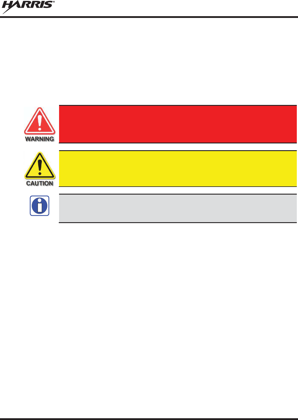
MM-014763-001, Rev. N
5
1 REGULATORY AND SAFETY INFORMATION
1.1 SAFETY SYMBOL CONVENTIONS
The following conventions are used in this manual to alert the user to general safety precautions that must
be observed during all phases of operation, installation, service, and repair of this product. Failure to
comply with these precautions or with specific warnings elsewhere violates safety standards of design,
manufacture, and intended use of the product. Harris Corporation assumes no liability for the customer's
failure to comply with these standards.
The WARNING symbol calls attention to a procedure, practice, or the like, which,
if not correctly performed or adhered to, could result in personal injury. Do not
proceed beyond a WARNING symbol until the conditions identified are fully
understood or met.
The
CAUTION
symbol calls attention to an operating procedure, practice, or the like,
which, if not performed correctly or adhered to, could result in damage to the equipment
or severely degrade equipment performance.
The
NOTE symbol calls attention to supplementa
l information, which may improve
system performance or clarify a process or procedure.
NOTE

MM-014763-001, Rev. N
6
1.2 REGULATORY APPROVALS
1.2.1 Applicable Type Acceptance/Certification Numbers
Table 1-1: FCC Type Acceptance
RADIO
PART NUMBER FREQUENCY
RANGE/WATTAGE
FCC TYPE
ACCEPTANCE
NUMBER
RU
-144750-041
136
-174 MHz, 50 Watt
OWDTR-055-E
RU
-144750-051
136
-
174 MHz, 110 Watt
OWDTR-056-E
RU
-144750-021
378
-430 MHz, 50 Watt
OWDTR-061-E
RU-144750-031
440-512 MHz, 50 Watt
OWDTR-062-E
14018-0010-01
330-380 MHz, 40 Watt
N/A1
RU
-144750-061 Rev. K or
earlier)
764
-806 MHz, 30 Watt
806
-870 MHz, 35 Watt
OWDTR-060-E
RU
-144750-061
(Rev. L or later)
764
-806 MHz, 30 Watt
806
-870 MHz, 35 Watt
OWDTR-0132-
E
RU
-144750-181
900 MHz, 30 Watt
OWDTR-049-E
Applicable FCC Rules: Part 15, Part 80*, and Part 90
* FCC Part 80 is for 156-162 MHz only.
Table 1-2: Industry Canada Type Acceptance
RADIO
PART NUMBER
FREQUENCY
RANGE/WATTAGE
IC TYPE ACCEPTANCE
NUMBER
RU
-144750-041
136
-174 MHz, 50 Watt
3636B-0055
RU
-144750-051
136
-
174 MHz, 110 Watt
3636B-0056
RU
-144750-021
378
-430 MHz, 50 Watt
3636B-0061
RU
-144750-031
440
-512 MHz, 50 Watt
3636B-0062
14018
-0010-01
330
-
380 MHz, 40 Watt
N/A
1
RU
-144750-061
(Rev.
K or earlier)
764
-806 MHz, 30 Watt
806
-870 MHz, 35 Watt
3636B-0051
RU
-144750-061
(Rev. L or later)
764
-806 MHz, 30 Watt
806
-870 MHz, 35 Watt
3636B-0132
RU
-144750-181
900 MHz, 30 Watt
3636B-0049
Applicable Industry Canada Rules: RSS 119; RSS 210
1 The 14018-0010-01 model is not sold or used in North America.
MM-014763-001, Rev. N
7
1.3 RADIO FREQUENCY INTERFERENCE
1.3.1 FCC Part 15
This device complies with Part 15 of the FCC Rules. Operation is subject to the following two conditions:
1. This device may not cause harmful interference; and,
2. This device must accept any interference received, including interference that may cause undesired
operation.
1.3.2 Industry Canada
This device complies with Industry Canada license-exempt RSS standard(s). Operation is subject to the
following two conditions: (1) this device may not cause interference, and (2) this device must accept any
interference, including interference that may cause undesired operation of the device.
Le présent appareil est conforme aux CNR d'Industrie Canada applicables aux appareils radio exempts de
licence. L'exploitation est autorisée aux deux conditions suivantes : (1) l'appareil ne doit pas produire de
brouillage, et (2) l'utilisateur de l'appareil doit accepter tout brouillage radioélectrique subi, même si le
brouillage est susceptible d'en compromettre le fonctionnement.
1.4 RF ENERGY EXPOSURE AWARENESS AND CONTROL
INFORMATION FOR FCC OCCUPATIONAL USE REQUIREMENTS
Before using the two-way mobile radio, review the following important RF energy awareness and
control information and operational instructions. Comply with this information and instructions to
ensure compliance with RF exposure guidelines.
This radio is intended for use in occupational/controlled conditions, where users
have full knowledge of their exposure and can exercise control over their exposure
to
remain below RF exposure
limits. This radio is NOT authorized for general
population, consumer, or any other use.
Changes or modifications not ex
pressly approved by Harris
could void the user's
authority to operate the equipment.
This two-way radio uses electromagnetic energy in the radio frequency (RF) spectrum to provide
communications between two or more users over a distance. It uses RF energy or radio waves to send and
receive calls. RF energy is one form of electromagnetic energy. Other forms include, but are not limited
to, electric power, sunlight, and x-rays. RF energy, however, should not be confused with these other
forms of electromagnetic energy, which, when used improperly, can cause biological damage. Very high
levels of x-rays, for example, can damage tissues and genetic material.
Experts in science, engineering, medicine, health, and industry work with organizations to develop
standards for exposure to RF energy. These standards provide recommended levels of RF exposure for
both workers and the general public. These recommended RF exposure levels include substantial margins

MM-014763-001, Rev. N
8
of protection. All two-way radios marketed in North America are designed, manufactured, and tested to
ensure they meet government-established RF exposure levels. In addition, manufacturers also recommend
specific operating instructions to users of two-way radios. These instructions are important because they
inform users about RF energy exposure and provide simple procedures on how to control it. Refer to the
following websites for more information on what RF energy exposure is and how to control exposure to
assure compliance with established RF exposure limits:
http://www.fcc.gov/oet/rfsafety/rf-faqs.html
http://www.osha.gov./SLTC/radiofrequencyradiation/index.html
1.4.1 Federal Communications Commission Regulations
Before it was marketed in the United States, the M5300, M7300, and XG-75M series two-way mobile
radios were tested to ensure compliance with FCC RF energy exposure limits for two-way mobile radios.
When two-way radios are used as a consequence of employment, the FCC requires users to be fully aware
of and able to control their exposure to meet occupational requirements. Exposure awareness can be
facilitated by the use of a label directing users to specific user awareness information. The radio has an
RF exposure product label. Also, this Product Safety Manual and the applicable Operator’s Manual
include information and operating instructions required to control RF exposure and to satisfy compliance
requirements.
1.5 COMPLIANCE WITH RF EXPOSURE STANDARDS
The M5300, M7300, and XG-75M series two-way mobile radios are designed and tested to comply with a
number of national and international standards and guidelines regarding human exposure to RF
electromagnetic energy. The radios comply with the IEEE and ICNIRP exposure limits for
occupational/controlled RF exposure environment at duty-cycle times of up to 50% (50% transmit, 50%
receive) and it is authorized by the FCC for occupational use. In terms of measuring RF energy for
compliance with the FCC exposure guidelines, each radio’s antenna radiates measurable RF energy only
while it is transmitting (talking), not when it is receiving (listening), or in a standby mode.
The M5300, M7300, and XG-75M series two-way mobile radios comply with the following RF energy
exposure standards and guidelines:
x United States Federal Communications Commission (FCC), Code of Federal Regulations; 47
CFR § 2 sub-part J.
x American National Standards Institute (ANSI)/Institute of Electrical and Electronic Engineers (IEEE)
C95.1-2005.
x Institute of Electrical and Electronic Engineers (IEEE) C95.1-2005.
x IC Standard RSS-102, Issue 4, 2010: Spectrum Management and Telecommunications Radio
Standards Specification. Radiofrequency Exposure Compliance of Radiocommunication Apparatus
(All Frequency Bands).
Table
1-3 and Table 1-4 list the recommended minimum safe lateral distances
for a
controlled environment and for unaware bystanders in an uncontrolled environment,
from transmitting antennas (i.e., monopoles over a ground plane, or dipoles) at rated
radio power for mobile radios installed in a vehicle. Transmit only when unaware
bystanders are at least the uncontrolled recommended minimum
safe
lateral distance
away from the transmitting antenna.

MM-014763-001, Rev. N
9
Based on the highest radiated RF power and the highest antenna gain in antennas used with M5300,
M7300, and XG-75M series radios, the distances listed in Table 1-3 and Table 1-4 are considered as safe
distances for controlled and uncontrolled environments with the M5300, M7300, and XG-75M series
mobile radios transmitting at a maximum 50% duty cycle:
1.5.1 Mobile Antennas
The antenna(s) for the radio must be installed in accordance with the antenna installation procedures
presented in the radio’s Installation Manual. Also refer to any special instructions included with the
antenna.
Use only approved/supplied antenna(s) or an approved replacement antenna. Unauthorized antennas,
modifications, or attachments can cause the FCC RF exposure limits to be exceeded.
1.5.2 Approved Accessories
The radio has been tested and meets FCC RF guidelines when used with accessories supplied or
designated for use with it. Use of other accessories may not ensure compliance with the FCC’s RF
exposure guidelines, and may violate FCC regulations. For a list of approved accessories, refer to the
radio’s Installation Manual and/or to the Products and Services Catalog.

MM-014763-001, Rev. N
10
1.5.3 Mobile Antennas (Vehicle Installations)
Table 1-3: Rated Power and Recommended Minimum Safe Lateral Distance
(Vehicle Installations)
MOBILE RADIO
FREQUENCY
SPLIT
ANTENNA
PART NUMBER
ANTENNA DESCRIPTION
RECOMMENDED MINIMUM LATERAL
HUMAN BODY DISTANCE FROM
TRANSMITTING ANTENNA
CONTROLLED
ENVIRONMENT
UNCONTROLLED
ENVIRONMENT
VHF (50 W)
AN-225002-001
136 to 174
MHz, 0
dBd Gain
24.8 Inches
(63 Centimeters)
55.1 Inches
(140 Centimeters)
VHF (50 W)
AN-225006-001
132 to 960
MHz, 0
dBd Gain*
VHF (50 W)
AN-225002-003
136 to 174
MHz, 3 dBd
Gain*
35.0 Inches
(89 Centimeters)
78.0 Inches
(198 Centimeters)
VHF (50 W)
AN-225002-004 136 to 174 MHz, 2.4
dBd
Gain* 32.7 Inches
(83 Centimeters)
72.8 Inches
(185 Centimeters)
VHF (110 W)
AN-225002-001
136 to 174
MHz, 0
dBd Gain
36.6 Inches
(93
Centimeters)
81.9 Inches
(208 Centimeters)
VHF (110 W)
AN-225006-001
132 to 960
MHz, 0
dBd Gain*
VHF (110 W)
AN-225002-003
136 to 174
MHz, 3
dBd Gain*
52.0 Inches
(132 Centimeters)
115.7 Inches
(294 Centimeters)
VHF (110 W)
AN-225002-004 136 to 174 MHz, 2.4
dBd
Gain* 48.4 Inches
(123 Centimeters)
107.9 Inches
(274 Centimeters)
UHF
–
L (50 W)
AN-125001-
001 (mount)
with
AN
-225003-
001 (element)
378 to 430
MHz Standard
Rooftop
-Mount; 0
dBd Gain
21.3 Inches
(54 Centimeters)
47.2 Inches
(120 Centimeters)
UHF
–
L (50 W)
AN-125001-
001 (mount)
with
AN
-225003-
004 (element)
378 to 430
MHz Standard
Rooftop
-Mount; Low-
Profile
0 dBd Gain
UHF
–
L (50 W)
AN-125001-
003 (mount)
with
AN
-225003-
001 (element)
378 to 430 MHz Thick
Rooftop
-Mount; 0 dBd
Gain
UHF
–
L (50 W)
AN-125001-
003 (mount)
with
AN
-225003-
004 (element)
378 to 430
MHz Thick
Rooftop
-Mount; Low-
Profile
0 dBd Gain
UHF
–
L (50 W)
AN-125001-
005 (mount)
with
AN
-225003-
001 (element)
378 to 430 MHz
GPS Combo, Standard
Rooftop
-Mount; 0
dBd Gain
UHF
–
L (50 W)
AN-125001-
005 (mount)
with
AN
-225003-
004 (element)
378 to 430 MHz
GPS Combo, Standard
Rooftop
-Mount; Low-
Profile
0 dBd Gain
UHF
–
L (50 W)
AN-125001-
007 (mount)
with
AN
-225003-
001 (element)
378 to 430
MHz Magnetic-
Mount;
0 dBd Gain
UHF
–
L (50 W)
AN-125001-
007 (mount)
with
AN
-225003-
004 (element)
378 to 430
MHz Magnetic-
Mount;
Low-Profile 0
dBd Gain
(Table Continued on Next Page)

MM-014763-001, Rev. N
11
Table 1-3: Rated Power and Recommended Minimum Safe Lateral Distance
(Vehicle Installations)
MOBILE RADIO
FREQUENCY
SPLIT
ANTENNA
PART NUMBER
ANTENNA DESCRIPTION
RECOMMENDED MINIMUM LATERAL
HUMAN BODY DISTANCE FROM
TRANSMITTING ANTENNA
CONTROLLED
ENVIRONMENT
UNCONTROLLED
ENVIRONMENT
UHF
–
H (50 W)
AN-125001-001 (mount)
with
AN-225004-001 (element)
450 to 512 MHz
Standard Rooftop-
Mount;
0 dBd Gain
20 Inches
(51 Centimeters)
45 Inches
(114 Centimeters)
UHF
–
H (50 W)
AN-125001-001 (mount)
with
AN-225004-004 (element)
450 to 512 MHz
Standard Rooftop-
Mount;
Low-Profile 0 dBd Gain
UHF
–
H (50 W)
AN-125001-003 (mount)
with
AN-225004-001 (element)
450 to 512 MHz
Thick Rooftop-Mount;
0 dBd Gain
UHF
–
H (50 W)
AN-125001-003 (mount)
with
AN-225004-004 (element)
450 to 512 MHz
Thick Rooftop-Mount;
Low-Profile 0 dBd Gain
UHF
–
H (50 W)
AN-125001-005 (mount)
with
AN-225004-001 (element)
450 to 512 MHz
GPS Combo, Standard
Rooftop-Mount; 0 dBd Gain
UHF
–
H (50 W)
AN-125001-
005 (mount)
with
AN
-225004-
004 (element)
450 to 512 MHz
GPS Combo, Standard
Rooftop
-Mount; Low-
Profile
0 dBd Gain
UHF
–
H (50 W)
AN-125001-007 (mount)
with
AN-225004-001 (element)
450 to 512 MHz
Magnetic-Mount;
0 dBd Gain
UHF
–
H (50 W)
AN-125001-007 (mount)
with
AN-225004-004 (element)
450 to 512 MHz
Magnetic
-Mount; Low-
Profile
0 dBd Gain
700/800 MHz
AN-125001-002 (mount)
with
AN-225001-001 (element)
700/800
MHz Standard
Rooftop
-Mount; 3
dBd Gain
9.8 Inches
(25 Centimeters)
21.7 Inches
(55 Centimeters)
700/800 MHz
AN-125001-002 (mount)
with
AN-225001-002 (element)
700/800 MHz Standard
Rooftop-Mount;
Elevated-Feed 3 dBd Gain
700/800 MHz
AN-125001-
002 (mount)
with
AN
-225001-
003 (element)
700/800 MHz Standard
Rooftop-
Mount; Elevated-
Feed, No Ground Plane
3 dBd Gain
700/800 MHz
AN-125001-002 (mount)
with
AN-225001-004 (element)
700/800 MHz Standard
Rooftop-Mount;
Low-Profile 2 dBd Gain
700/800 MHz
AN-125001-002 (mount)
with
AN-225001-005 (element)
700/800
MHz Standard
Rooftop
-Mount; 5
dBd Gain
11.8 Inches
(30 Centimeters)
23.6 Inches
(60 Centimeters)
700/800 MHz
AN-125001-004 (mount)
with
AN-225001-001 (element)
700/800 MHz Thick
Rooftop
-Mount; 3
dBd Gain
9.8 Inches
(25 Centimeters)
21.7 Inches
(55 Centimeters)
(Table Continued on Next Page)

MM-014763-001, Rev. N
12
Table 1-3: Rated Power and Recommended Minimum Safe Lateral Distance
(Vehicle Installations)
MOBILE RADIO
FREQUENCY
SPLIT
ANTENNA
PART NUMBER
ANTENNA DESCRIPTION
RECOMMENDED MINIMUM LATERAL
HUMAN BODY DISTANCE FROM
TRANSMITTING ANTENNA
CONTROLLED
ENVIRONMENT
UNCONTROLLED
ENVIRONMENT
700/800 MHz
AN-125001-004 (mount)
with
AN-225001-002 (element)
700/800 MHz Thick
Rooftop-
Mount; Elevated-
Feed 3 dBd Gain
9.8 Inches
(25 Centimeters)
21.7 Inches
(55 Centimeters)
700/800 MHz
AN-125001-
004 (mount)
with
AN
-225001-
003 (element)
700/800 MHz Thick
Rooftop-
Mount; Elevated-
Feed, No Ground Plane
3 dBd Gain
700/800 MHz
AN-125001-004 (mount)
with
AN-225001-004 (element)
700/800 MHz Thick
Rooftop
-Mount; Low-
Profile
2 dBd Gain
700/800 MHz
AN-125001-004 (mount)
with
AN-225001-005 (element)
700/800 MHz Thick
Rooftop
-Mount; 5
dBd Gain
11.8 Inches
(30 Centimeters)
23.6 Inches
(60 Centimeters)
700/800 MHz
AN-125001-006 (mount)
with
AN-225001-001 (element)
700/800 MHz GPS Combo
Rooftop-Mount; 3
dBd /
5.15 dBi Gain
9.8 Inches
(25 Centimeters)
21.7 Inches
(55 Centimeters)
700/800 MHz
AN-125001-006 (mount)
with
AN-225001-002 (element)
700/800 MHz GPS Combo
Rooftop-Mount;
Elevated-Feed 3 dBd Gain
700/800 MHz
AN-125001-
006 (mount)
with
AN
-225001-
003 (element)
700/800 MHz GPS Combo
Rooftop-
Mount; Elevated-
Feed, No Ground Plane
3 dBd Gain
700/800 MHz
AN-125001-006 (mount)
with
AN-225001-004 (element)
700/800 MHz GPS Combo
Rooftop
-Mount; Low-
Profile
2 dBd Gain
700/800 MHz
AN-125001-006 (mount)
with
AN-225001-005 (element)
700/800 MHz GPS Combo
Rooftop-Mount; 5
dBd /
7.15 dBi Gain
11.8 Inches
(30 Centimeters)
23.6 Inches
(60 Centimeters)
700/800 MHz
AN-125001-008 (mount)
with
AN-225001-001 (element)
700/800 MHz Magnetic
-
Mount; 3 dBd Gain
9.8 Inches
(25 Centimeters)
21.7 Inches
(55 Centimeters)
700/800 MHz
AN-125001-008 (mount)
with
AN-225001-002 (element)
700/800 MHz Magnetic-
Mount;
Elevated-Feed 3 dBd Gain
700/800 MHz
AN-125001-008 (mount)
with
AN-225001-003 (element)
700/800 MHz Magnetic-
Mount; Elevated-
Feed, No
Ground Plane 3 dBd Gain
700/800 MHz
AN-125001-008 (mount)
with
AN-225001-004 (element)
700/800 MHz Magnetic-
Mount;
Low-Profile 2 dBd Gain
700/800 MHz
AN-125001-008 (mount)
with
AN-225001-005 (element)
700/800 MHz Magnetic
-
Mount; 5 dBd Gain 11.8 Inches
(30 Centimeters)
23.6 Inches
(60 Centimeters)
(Table Continued on Next Page)

MM-014763-001, Rev. N
13
Table 1-3: Rated Power and Recommended Minimum Safe Lateral Distance
(Vehicle Installations)
MOBILE RADIO
FREQUENCY
SPLIT
ANTENNA
PART NUMBER
ANTENNA DESCRIPTION
RECOMMENDED MINIMUM LATERAL
HUMAN BODY DISTANCE FROM
TRANSMITTING ANTENNA
CONTROLLED
ENVIRONMENT
UNCONTROLLED
ENVIRONMENT
700/800 MHz
STI-Co
CCAS-SB-700
760 - 820 MHz Concealed
Peal-and-
Stick Internal-
Mount; dBi Gain
7.9 Inches
(20 Centimeters)
19.7 Inches
(50 Centimeters)
900 MHz
AN-125001-002 (mount)
with AN-225005-
001
(element)
900 MHz Standard
Rooftop-Mount;
3 dBd Gain
20 inches
(51 centimeters)
44.5 inches
(113 centimeters)
900 MHz
AN-125001-002 (mount)
with
AN-225005-002 (element)
900 MHz Standard
Rooftop-Mount;
Elevated-Feed 3 dBd Gain
900 MHz AN-125001-
002 (mount)
with
AN
-225005-
003 (element)
900 MHz Standard
Rooftop-Mount;
Elevated
-Feed No
Ground-
Plane 3 dBd Gain
900 MHz
AN-125001-002 (mount)
with
AN-225005-004 (element)
900 MHz Standard
Rooftop-Mount;
Low-Profile 2 dBd Gain
900 MHz AN-125001-
002 (mount)
with
AN
-225006-
001 (element)
132 to 960 MHz,
¼-Wavelength*;
Standard Rooftop-
Mount;
0 dBd Gain; Field-Tuned
900 MHz
AN-125001-004 (mount)
with
AN-225005-001 (element)
900 MHz Thick
Rooftop-Mount;
3 dBd Gain
20 inches
(51 centimeters)
44.5 inches
(113 centimeters)
900 MHz
AN-125001-004 (mount)
with AN-225005-
002
(element)
900 MHz Thick
Rooftop-Mount;
Elevated-Feed 3 dBd Gain
900 MHz AN-125001-
004 (mount)
with
AN
-225005-
003 (element)
900 MHz Thick
Rooftop-Mount;
Elevated
-
Feed No Ground-
Plane 3 dBd Gain
900 MHz
AN-125001-004 (mount)
with
AN-225005-004 (element)
900 MHz Thick
Rooftop-Mount;
Low-Profile 2 dBd Gain
900 MHz AN-125001-
004 (mount)
with AN-225006-
001
(element)
132 to 960 MHz,
¼-Wavelength*;
Thick Rooftop-Mount;
0 dBd Gain; Field-Tuned
900 MHz
AN-125001-006 (mount)
with
AN-225005-001 (element)
900 MHz GPS Combo
Rooftop-Mount;
3 dBd Gain
20 inches
(51 centimeters)
44.5 inches
(113 centimeters)
900 MHz
AN-125001-006 (mount)
with AN-225005-
002
(element)
900 MHz GPS Combo
Rooftop-Mount;
Elevated-Feed 3 dBd Gain
(Table Continued on Next Page)

MM-014763-001, Rev. N
14
Table 1-3: Rated Power and Recommended Minimum Safe Lateral Distance
(Vehicle Installations)
MOBILE RADIO
FREQUENCY
SPLIT
ANTENNA
PART NUMBER
ANTENNA DESCRIPTION
RECOMMENDED MINIMUM LATERAL
HUMAN BODY DISTANCE FROM
TRANSMITTING ANTENNA
CONTROLLED
ENVIRONMENT
UNCONTROLLED
ENVIRONMENT
900 MHz AN-125001-
006 (mount)
with
AN
-225005-
003 (element)
900 MHz GPS Combo
Rooftop-Mount;
Elevated
-
Feed No Ground-
Plane 3 dBd Gain
9.8 Inches
(25 Centimeters)
21.7 Inches
(55 Centimeters)
900 MHz
AN-125001-006 (mount)
with
AN-225005-004 (element)
900 MHz GPS Combo
Rooftop-Mount;
Low-Profile 2 dBd Gain
900 MHz AN-125001-
006 (mount)
with AN-225006-
001
(element)
132 to 960 MHz,
¼-Wavelength*;
GPS Combo Rooftop
-
Mount;
0 dBd Gain; Field-Tuned
900 MHz
AN-125001-008 (mount)
with
AN-225005-001 (element)
900 MHz Magnetic-
Mount
3 dBd Gain
20 inches
(51 centimeters)
44.5 inches
(113 centimeters)
900 MHz
AN-125001-008 (mount)
with
AN-225005-002 (element)
900 MHz Magnetic-
Mount
Elevated-Feed 3
dBd Gain
900 MHz
AN-125001-008 (mount)
with
AN-225005-003 (element)
900 MHz Magnetic-Mount
Elevated
-
Feed No Ground-
Plane 3 dBd Gain
900 MHz
AN-125001-008 (mount)
with
AN-225005-004 (element)
900 MHz Magnetic-
Mount
Low-Profile 2
dBd Gain
900 MHz AN-125001-
008 (mount)
with
AN
-225006-
001 (element)
132 to 960 MHz,
¼-Wavelength*;
Magnetic-Mount;
0 dBd Gain; Field-Tuned
900 MHz AN102800V1
(Discontinued)
136 – 941 MHz Standard
Rooftop-Mount; ¼-
Wave
Unity-Gain**
20 inches
(51 centimeters)
44.5 inches
(113 centimeters)
900 MHz Astron NMO9000
890 to 950 MHz NMO-Mount
Radome 3 dBi Gain
15.8 inches
(40 centimeters)
34.6 inches
(88 centimeters)
* Element must be trimmed to proper length to minimize antenna system VSWR.
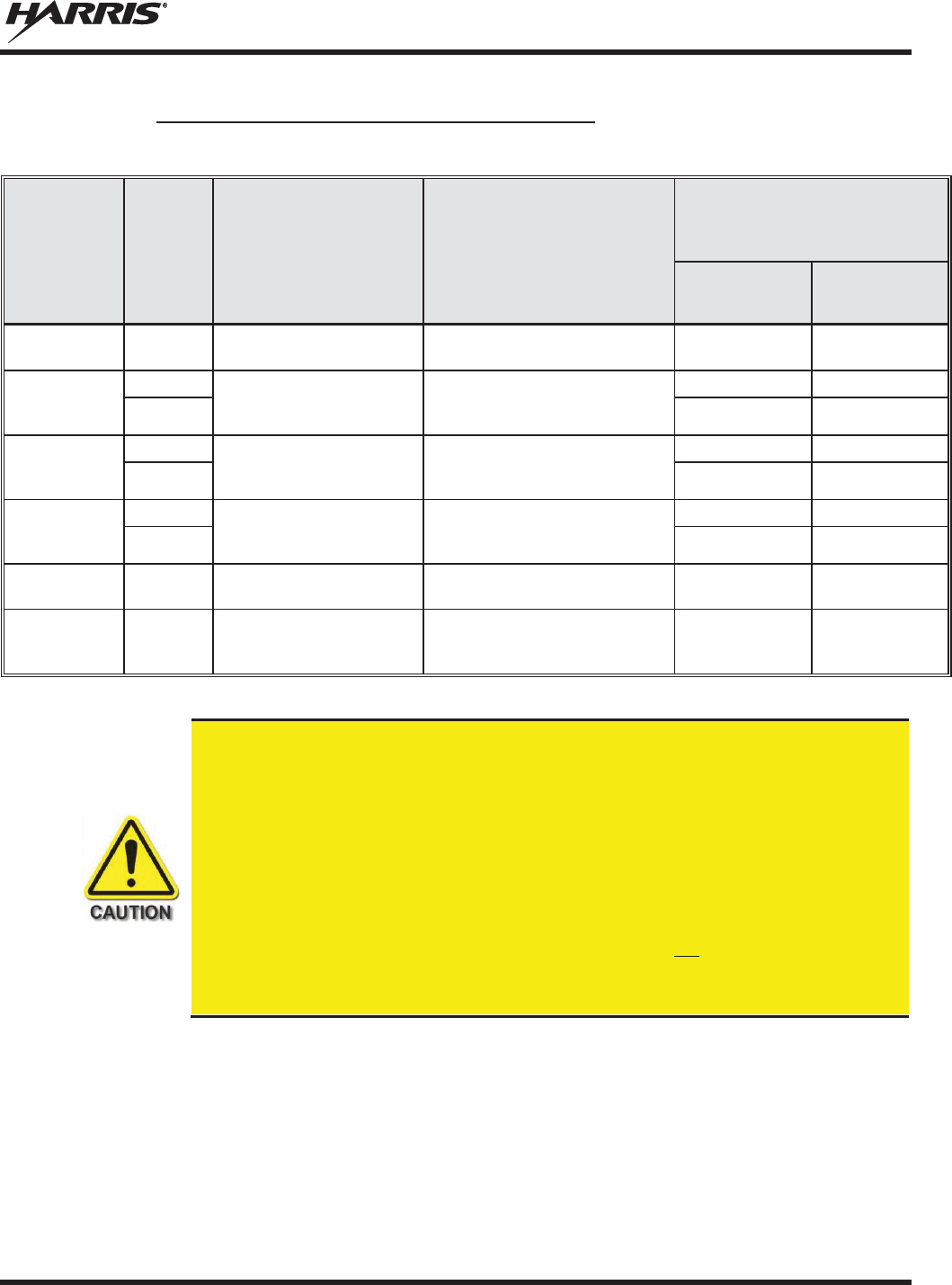
MM-014763-001, Rev. N
15
1.5.4 Mobile Antennas (Motorcycle Installations)
Table 1-4: Rated Power and Recommended Minimum Safe Lateral Distance (Motorcycle Installation)
RF
BAND
MAX. TX
POWER
(WATTS)
ANTENNA
PART NUMBER ANTENNA DESCRIPTION
RECOMMENDED MINIMUM
LATERAL HUMAN BODY
DISTANCE FROM TRANSMITTING
ANTENNA
CONTROLLED
ENVIRONMENT
(Centimeters)
UNCONTROLLED
ENVIRONMENT
(Centimeters)
VHF 20
LE-
OM150K.125/TNC
136 to 174 MHz Motorcycle-
Mount; 2.5 dBd Gain
53 118
VHF
18
AN-125001-005 (mount)
with
AN-225002-004 (element)
136 to 174 MHz GPS Combo;
No-Ground-
Plane (NGP);
2.4 dBd Gain
50
—
3.6
— 50
UHF- L
43
AN-125001-005 (mount)
with
AN-225003-005 (element)
378 to 430 MHz GPS Combo,
No
-Ground-Plane (NGP), 0
dBd
Gain
50
—
8.5
— 50
UHF - H
47
AN-125001-005 (mount)
with
AN-225004-005 (element)
450 to 512 MHz GPS Combo,
No
-Ground-Plane (NGP), 0
dBd
Gain
50
—
9.5
— 50
800 MHz
20
LE
-
OM806HDBKTNCDS
800 MHz Motorcycle-Mount;
3.5 dBd Gain
28 72
700 or 800 MHz
20
AN-125001-006 (mount)
with
AN-225001-003 (element)
700/800 MHz GPS Combo; no-
Ground-Plane (NGP);
3 dBd / 5.15 dBi Gain
50 50
A radio used in a motorcycle installation must be configured with a transmit output
power level less than or equal to the
MAX. TX POWER (WATTS)
specification listed in
Table
1-4
for the respective frequency band and antenna/antenna element. Refer to the
radio’s
Installation Manual for additional information.
When
a later-design motorcycle
installation kit is employed (which uses antenna
element AN
-225001-003 or AN-225002-
004), the coaxial cable between the radio and
the base of the antenna mount cannot be shorter than 44
inches (111.8
centimeters).
Refer to the radio’s
Installation Manual for additional information.
A radio intended for a non
-motorcycle installation should not
be used in a motorcycle
installation unless it is reprogrammed per the procedures presented in the radio’s
Installation Manual
.

MM-014763-001, Rev. N
16
1.6 OCCUPATIONAL SAFETY GUIDELINES AND SAFETY TRAINING
INFORMATION
To ensure bodily exposure to RF electromagnetic energy is within the FCC allowable limits for
occupational use. Always adhere to the following basic guidelines:
x The push-to-talk button should only be depressed when intending to send a voice message.
x The radio should only be used for necessary work-related communications.
x The radio should only be used by authorized and trained personnel. It should never be operated by
children.
x Do not attempt any unauthorized modification to the radio. Changes or modifications to the radio may
cause harmful interference and/or cause it to exceed FCC RF exposure limits. Only qualified
personnel should service the radio.
x Always use only authorized accessories (antennas, control heads, speakers/mics, etc.). Use of
unauthorized accessories can cause the FCC RF exposure compliance requirements to be exceeded.
The information listed above provides the user with information needed to make him or her aware of a RF
exposure, and what to do to assure that this radio operates within the FCC exposure limits of this radio.
1.7 COMMON HAZARDS
The operator of any mobile radio should be aware of certain hazards common to
the operation of vehicular radio transmissions. Possible hazards include but are not
limited to:
x Explosive Atmospheres — Just as it is dangerous to fuel a vehicle while its engine is running, be
sure to turn the radio OFF while fueling the vehicle. If the radio is mounted in the trunk of the
vehicle, DO NOT carry containers of fuel in the trunk.
Areas with potentially explosive atmosphere are often, but not always, clearly marked. Turn the radio
OFF when in any area with a potentially explosive atmosphere. It is rare, but not impossible that the
radio or its accessories could generate sparks.
x Interference To Vehicular Electronic Systems — Electronic fuel injection systems, electronic anti-
skid braking systems, electronic cruise control systems, etc., are typical of the types of electronic
devices that can malfunction due to the lack of protection from radio frequency (RF) energy present
when transmitting. If the vehicle contains such equipment, consult the dealer for the make of vehicle
and enlist his aid in determining if such electronic circuits perform normally when the radio is
transmitting.
x Electric Blasting Caps — To prevent accidental detonation of electric blasting caps, DO NOT use
two-way radios within 1000 feet (305 meters) of blasting operations. Always obey the “Turn Off
Two-Way Radios” (or equivalent) signs posted where electric blasting caps are being used. (OSHA
Standard: 1926.900).
x Radio Frequency Energy — To prevent burns or related physical injury from radio frequency
energy, do not operate the transmitter when anyone outside of the vehicle is within the minimum safe
distance from the antenna as specified in Table 1-3 and Table 1-4. Refer to Section 1.2 for additional
information.

MM-014763-001, Rev. N
17
x Vehicles Powered By Liquefied Petroleum (LP) Gas — Radio installation in vehicles powered by
liquefied petroleum gas, where the LP gas container is located in the trunk or other sealed-off space
within the interior of the vehicle, must conform to the National Fire Protection Association standard
NFPA 58. This requires:
¾ The space containing the radio equipment must be isolated by a seal from the space containing
the LP gas container and its fittings.
¾ Outside filling connections must be used for the LP gas container.
¾ The LP gas container space shall be vented to the outside of the vehicle.
x Vehicles Equipped with Airbags — For driver and passenger safety, avoid mounting the radio’s
control head (or any other component) above or near airbag deployment areas. In addition to driver-
side and passenger-side front-impact airbags, some vehicles may also be equipped with side-impact
airbags. For occupant safety, verify the location of all airbags within the vehicle before installing the
radio equipment.
1.8 SAFE DRIVING RECOMMENDATIONS
The American Automobile Association (AAA) advocates the following key safe driving recommenda-
tions:
x Read the literature on the safe operation of the radio.
x Keep both hands on the steering wheel and the microphone in its hanger whenever the vehicle is in
motion.
x Place calls only when the vehicle is stopped.
x When talking from a moving vehicle is unavoidable, drive in the slower lane. Keep conversations
brief.
x If a conversation requires taking notes or complex thought, stop the vehicle in a safe place and
continue the call.
x Whenever using a mobile radio, exercise caution.
1.9 OPERATING RULES AND REGULATIONS
Two-way radio systems must be operated in accordance with the rules and regulations of the local,
regional, or national government.
In the United States, the XG-75M/M7300 mobile radio must be operated in accordance with the rules and
regulations of the Federal Communications Commission (FCC). Operators of two-way radio equipment
must be thoroughly familiar with the rules that apply to the particular type of radio operation. Following
these rules helps eliminate confusion, assures the most efficient use of the existing radio channels, and
results in a smoothly functioning radio network.
Under U.S. law, operation of an unlicensed radio transmitter within the jurisdiction of
the United States may be punishable by a fine of up to $10,000, imprisonment for up to
two (2) years, or both.
When using a two-way radio, remember these rules:
MM-014763-001, Rev. N
18
x It is a violation of FCC rules to interrupt any distress or emergency message. The radio operates in
much the same way as a telephone “party line.” Therefore, always listen to make sure the channel is
clear before transmitting. Emergency calls have priority over all other messages. If someone is
sending an emergency message – such as reporting a fire or asking for help in an accident, do not
transmit unless assistance can be offered.
x The use of profane or obscene language is prohibited by Federal law.
x It is against the law to send false call letters or false distress or emergency messages. The FCC
requires keeping conversations brief and confined to business. Use coded messages whenever
possible to save time.
x Using the radio to send personal messages (except in an emergency) is a violation of FCC rules. Send
only essential messages.
x It is against Federal law to repeat or otherwise make known anything overheard on the radio.
Conversations between others sharing the channel must be regarded as confidential.
x The FCC requires self-identification at certain specific times by means of call letters. Refer to the
rules that apply to the particular type of operation for the proper procedure.
x No changes or adjustments shall be made to the equipment except by an authorized or certified
electronics technician.
1.10 OPERATING TIPS
The following conditions tend to reduce the effective range of two-way radios and should be avoided
whenever possible:
x Operating the radio in areas of low terrain, or while under power lines or bridges.
x Obstructions such as mountains and buildings.
In areas where transmission or reception is poor, communication improvement may
sometimes be obtained by moving a few yards in another direction, or moving to a
higher elevation.
NOTE
MM-014763-001, Rev. N
19
2 RENSEIGNEMENTS SUR LA RÉGLEMENTATION ET
SÉCURITÉ
2.1 CONVENTIONS SUR LES SYMBOLES DE SÉCURITÉ
Les conventions suivantes sont utilisées dans le présent manuel pour avertir l’utilisateur des précautions
générales de sécurité qui doivent être observées pendant toutes les phases d’opération, d’entretien et de
réparation de ce produit. Le non-respect de ces précautions ou d’avertissements précisés ailleurs enfreint
les normes de sécurité de la conception, de la fabrication et de l’utilisation prévue du produit. Harris
n’assume aucune responsabilité pour le non-respect de ces normes par le client.
Le symbole MISE EN GARDE attire l
’
attention sur une procédure ou une
pratique qui, si elle n
’est pa
s correctement effectuée ou observée, pourrait
entraîner une blessure personnelle. Ne pas poursuivre au
-delà d’
un symbole de
MISE EN GARDE avant que les conditions identifiées soient complètement
comprises ou satisfaites.
Le symbole
AVERTISSEMENT attire l’
attention sur une procédure ou une pratique
opérationnelle qui, si elle n
’
est pas correctement effectuée ou observée, pourrait
entraîner un bris d
’équipement ou une importante baisse de rendement de l’
équipement.
Le symbole
REMARQUE attire l’
attention sur des renseignements supplémentaires qui
peuvent améliorer le rendement du système ou clarifier un processus ou une procédure.
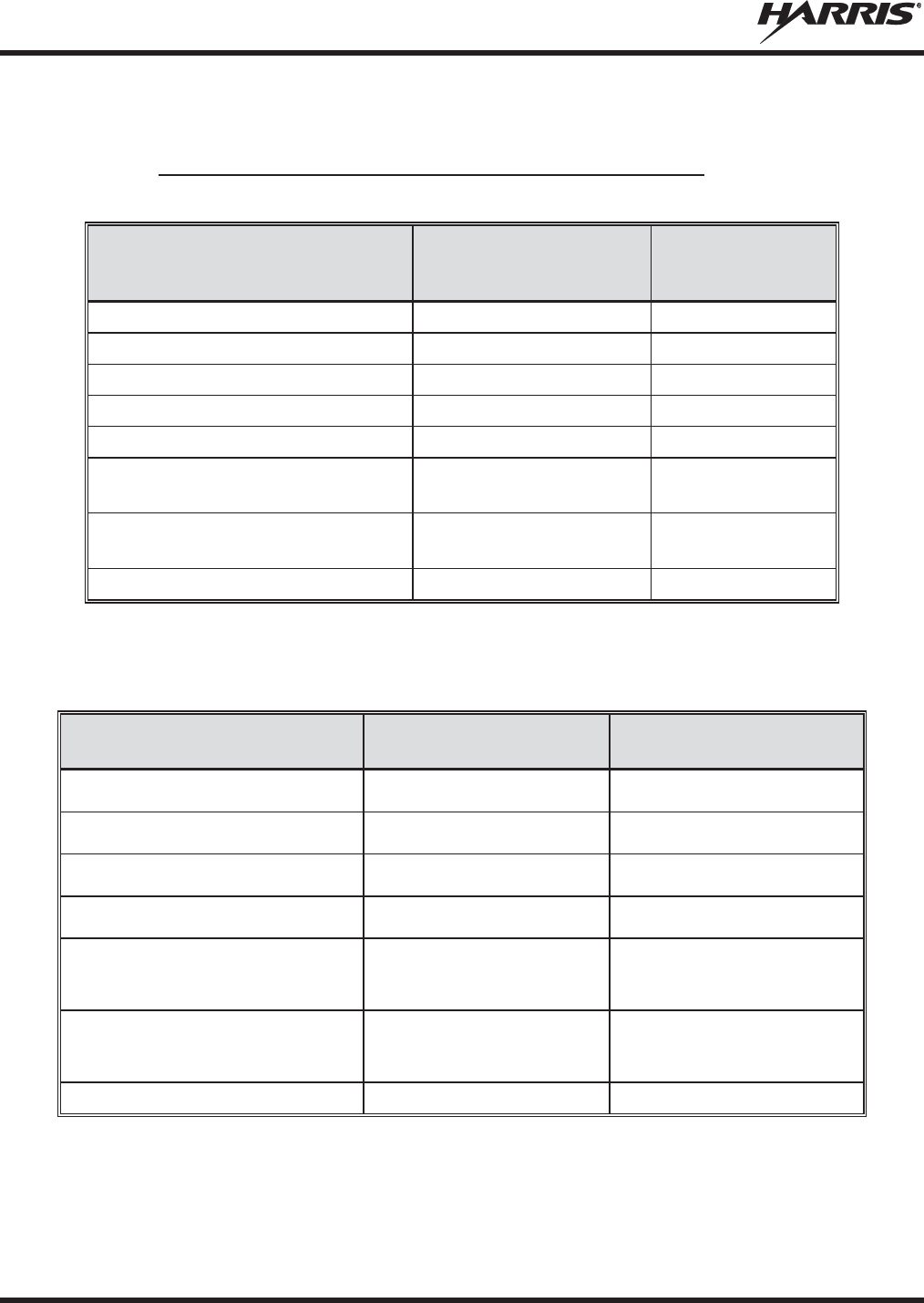
MM-014763-001, Rev. N
20
2.2 CONFORMITÉ À LA RÉGLEMENTATION
2.2.1 Type Applicable Numéros Acceptation / Certification
Tableau 2-1: FCC Type de Acceptation
NUMÉRO DE PIÈCE
DE LA RADIO FRÉQUENCE
RADIO/WATTAGE
FCC TYPE
NOMBRE
ACCEPTATION
RU
-144750-041
VHF
136-
174 MHz, 50 Watt
OWDTR-055-E
RU
-144750-051
VHF
136-
174 MHz, 110 Watt
OWDTR-056-E
RU
-144750-021
UHF
-L 378-
430 MHz, 50 Watt
OWDTR-061-E
RU
-144750-031
UHF
-H 440-
512 MHz, 50 Watt
OWDTR-062-E
14018
-0010-01
330
-380 MHz, 40 Watt N/R
RU
-144750-061 (Rev. K or earlier)
764
-806 MHz, 30 Watt
806
-870 MHz, 35 Watt OWDTR-060-E
RU
-144750-061 (Rev. L or later)
764
-806 MHz, 30 Watt
806
-870 MHz, 35 Watt OWDTR-0132-
E
RU
-144750-181
900 MHz, 30 Watt
OWDTR-049-E
règles de la FCC applicables: Partie 15, Partie 80*, and Partie 90
* FCC Part 80 est à 156-162 MHz only.
Tableau 2-2: Type de Canada Industrie Acceptation
NUMÉRO DE PIÈCE
DE LA RADIO
FRÉQUENCE
RADIO/WATTAGE
CANADA INDUSTRIE TYPE
NOMBRE ACCEPTATION
RU
-144750-041
VHF
136-
174 MHz, 50 Watt
3636B-0055
RU
-144750-051
VHF
136-
174 MHz, 110 Watt
3636B-0056
RU
-144750-021
UHF
-L 378-
430 MHz, 50 Watt
3636B-0061
RU
-144750-031
UHF
-H 440-
512 MHz, 50 Watt
3636B-0062
RU
-144750-061 (Rev. K or earlier)
764
-806 MHz, 30 Watt
806
-870 MHz, 35 Watt 3636B-0051
RU
-144750-061 (Rev. L or later)
764
-806 MHz, 30 Watt
806
-870 MHz, 35 Watt 3636B-0132
RU
-144750-181
900 MHz, 30 Watt
3636B-0049
Reglement applicables d'Industrie Canada: RSS 119; RSS 210
MM-014763-001, Rev. N
21
2.3 INTERFÉRENCE DES RADIOFRÉQUENCES
2.3.1 Partie 15 de la FCC
Cet appareil est conforme à la Partie 15 de la réglementation de la FCC. Le fonctionnement est soumis
aux deux conditions suivantes :
1. Cet appareil ne doit pas causer une interférence nuisible; et
2. Cet appareil doit accepter toute interférence reçue, y compris une interférence qui peut causer un
fonctionnement non souhaité.
2.3.2 Industrie Canada
Cet appareil est conforme aux normes RSS exemptées de licence d’Industrie Canada. Le fonctionnement
est soumis aux deux conditions suivantes : (1) cet appareil ne doit pas causer d’interférence et (2) cet
appareil doit accepter toute interférence, y compris une interférence qui peut causer un fonctionnement
non souhaité de l’appareil.
2.4 RENSEIGNEMENTS SUR UNE EXPOSITION À L’ÉNERGIE DES RF
2.4.1 Renseignements Sur Le Contrôle Et La Sensibilisation À L’énergie Des
RF Pour Les Exigences D’une Utilisation Professionnelle De La FCC
Avant d’utiliser les radios mobiles bidirectionnelles, passez en revue les renseignements et les
instructions opérationnelles importants suivants sur le contrôle et la sensibilisation à l’énergie des
RF. Se conformer à ces renseignements et instructions pour assurer la conformité aux directives
d’exposition aux RF.
Cette radio est destinée à être utilisée dans des conditions professionnelles/
contrôlées, où
les utilisateurs ont une pleine connaissance de leur exposition et
peuvent exercer un contrôle sur leur exposition pour rester sous les limites
d
’exposition aux RF. Cette radio N’
est PAS autorisée pour la population générale,
les consommateurs ou toute
autre utilisation.
Des changements ou modifications non expressément approuvés par Harris pourraient
annuler le droit d
’utilisation de l’équipement pour l’utilisateur.
Cette radio bidirectionnelle utilise une énergie électromagnétique dans le spectre des radiofréquences
(RF) pour permettre une communication à distance entre deux utilisateurs ou plus. Elle utilise l’énergie
des RF ou les ondes radio pour envoyer et recevoir des appels. L’énergie des RF est une forme d’énergie
électromagnétique. D’autres formes comprennent, entre autres, l’énergie électrique, la lumière du soleil et
les rayons X. Toutefois, l’énergie des RF ne doit pas être confondue avec ces autres formes d’énergie
électromagnétique qui, lorsque mal utilisées, peuvent causer des dommages biologiques. Par exemple, des
niveaux très élevés de rayons X peuvent endommager les tissus et le matériel génétique.
Des experts en science, en ingénierie, en médecine, en santé et de l’industrie travaillent avec des
organismes pour établir des normes pour l’exposition à l’énergie des RF. Ces normes procurent des
niveaux recommandés d’exposition aux RF autant aux travailleurs qu’au grand public. Ces niveaux
d’exposition aux RF recommandés comprennent d’importantes marges de protection. Toutes les radios

MM-014763-001, Rev. N
22
bidirectionnelles commercialisées en Amérique du Nord sont conçues, fabriquées et testées pour s’assurer
qu’elles satisfont les niveaux d’exposition aux RF établis par le gouvernement. Les fabricants
recommandent également des consignes d’utilisation particulières aux utilisateurs de radios
bidirectionnelles. Ces instructions sont importantes, car elles informent les utilisateurs sur l’exposition à
l’énergie des RF et donnent des procédures simples sur la manière de contrôler cette exposition.
Consultez les sites Web suivants (en anglais) pour de plus amples renseignements sur ce qu’est
l’exposition à l’énergie des RF et comment contrôler l’exposition pour assurer la conformité aux limites
d’exposition établies :
http://www.fcc.gov/oet/rfsafety/rf-faqs.html
http://www.osha.gov./SLTC/radiofrequencyradiation/index.html
2.4.1.1 Règlements de la Federal Communications Commission (« Commission
fédérale des communications » aux États-Unis)
Avant d’être mise sur le marché aux États-Unis, la radio mobile bidirectionnelle XG-75M/M7300 a été
testée pour s’assurer de sa conformité aux limites d’exposition à l’énergie des RF de la FCC pour les
radios mobiles bidirectionnelles. Lorsque les radios bidirectionnelles sont utilisées à la suite d’une
embauche, la FCC demande aux utilisateurs de bien connaître et de pouvoir contrôler leur exposition pour
satisfaire les exigences professionnelles. La sensibilisation à l’exposition peut être facilitée par
l’utilisation d’une étiquette qui dirige les utilisateurs vers des renseignements particuliers sur la
sensibilisation de l’utilisateur. La radio possède une étiquette de produit sur l’exposition aux RF. De plus,
le Manuel sur la sécurité du produit et le présent Manuel de l’opérateur comprennent des renseignements
et les consignes d’utilisation nécessaires pour contrôler l’exposition aux RF et pour satisfaire les
exigences de conformité.
2.5 CONFORMITÉ AUX NORMES D’EXPOSITION AUX RF
La radio mobile bidirectionnelle XG-75M/M7300 est conçue et testée pour être conforme à un certain
nombre de normes et directives nationales et internationales quant à l’exposition humaine à l’énergie
électromagnétique des RF. Cette radio est conforme aux limites d’exposition de l’IEEE et de la
Commission internationale de protection contre les rayonnements non ionisants pour un environnement
professionnel/contrôlé d’exposition aux RF à des périodes de cycle de service allant jusqu’à 50 % (50 %
de transmission, 50 % de réception) et elle est autorisée par la FCC pour une utilisation professionnelle.
Sur le plan de la mesure de l’énergie des RF pour la conformité aux directives d’exposition de la FCC,
l’antenne de la radio irradie une énergie des RF mesurable seulement lorsqu’elle transmet (parler), et non
lorsqu’elle reçoit (écouter) ou en mode d’attente.
La radio mobile bidirectionnelle XG-75M/M7300 est conforme aux normes et directives d’exposition à
l’énergie des RF suivantes :
x Federal Communications Commission (FCC) américaine, le Code of Federal Regulations; 47 CFR
§ 2 sous-partie J.
x American National Standards Institute (ANSI)/Institute of Electrical and Electronic Engineers (IEEE)
C95.1-2005.
x Institute of Electrical and Electronic Engineers (IEEE) C95.1-2005.
x IC Standard RSS-102, numéro 4, 2010 : Spectrum Management and Telecommunications Radio
Standards Specification. Radiofrequency Exposure Compliance of Radiocommunication Apparatus
(All Frequency Bands).
MM-014763-001, Rev. N
23
Tableau
2-3 par Tableau 2-4
indiquent les distances latérales sécuritaires minimales
recommandées pour un environnement contrôlé et pour les spectateurs ignorants dans
un environnement non contrôlé, d
’antennes de transmission (c.-à-
d., des monopôles sur
un plan de sol, ou des dipôles) à une puissance de radio évaluée pour les radios mobiles
installées dans un véhicule. Ils ne transmettent que lorsque les spectateurs ignorants
sont au moins à la distance latérale sécuritaire minimale recommandée non contrôlée de
l’
antenne de transmission.
Basées sur la puissance des RF irradiées la plus élevée et le gain d’antenne le plus élevé dans les antennes
à utiliser avec le M5300/M7300/XG-75M, les distances indiquées dans les Tableau 2-4 (pour une radio de
motocyclette), Tableau 2-3 (pour la M7300/XG-75M, 136 à 174 MHz, 50-Watt), (pour la M7300/XG-
75M, 136 à 174 MHz, 110-Watt), (pour la M7300/XG-75M, 378 à 512 MHz), (pour la
M5300/M7300/XG-75M, 700/800 MHz), et (pour la M5300, 900 MHz) sont considérées comme des
distances sécuritaires pour des environnements contrôlés et non contrôlés avec la radio mobile
M5300/M7300/XG-75M qui transmet à un cycle de service maximal de 50 %.
2.5.1 Antennes mobiles
Les antennes pour la radio doivent être installées conformément aux procédures présentées dans le
Manuel sur la sécurité du produit et dans le Manuel d’installation. L’installation est limitée à un ou des
véhicules motorisés en métal avec des plans au sol appropriés.
Utilisez uniquement les antennes approuvées/fournies ou une antenne de remplacement approuvée. Des
antennes, des modifications ou des accessoires non autorisés peuvent causer un dépassement des limites
d’exposition aux RF de la FCC.
2.5.2 Accessoires approuvés
La radio a été testée et satisfait les directives de RF de la FCC lorsqu’elle est utilisée avec les accessoires
fournis ou conçus pour être utilisés avec elle. L’utilisation d’autres accessoires peut ne pas garantir la
conformité aux directives d’exposition de la FCC et peut enfreindre la réglementation de la FCC. Pour
une liste d’accessoires approuvés, consultez le Manuel d’installation ou le Catalogue de produits et
services de Harris.
Utilisez toujours des accessoires autorisés Harris (antennes, haut
-
parleurs/micros,
etc.). L
’utilisation d’
accessoires non autorisés peut entraîner un dépassement des
exigences de conformité pour une exposition aux RF professionnelle ou contrôlée
de la FCC.

MM-014763-001, Rev. N
24
2.5.3 Monté Antennes (véhicule)
Tableau 2-3 : Distance latérale sécuritaire minimale recommandée d’une antenne de transmissio
n
branchée sur une radio mobile
RF
BAND
NUMÉRO DE PIÈCE DE
L’ÉLÉMENT DE
L’ANTENNE
DESCRIPTION DE
L’ANTENNE
DISTANCE MINIMALE RECOMMANDÉE DE
L
’
ANTENNE DE TRANSMISSION POUR LE
CORPS HUMAIN
ENVIRONNEMENT
CONTRÔLÉ
ENVIRONNEMENT NON
CONTRÔLÉ
VHF (50 W)
AN-225002-001
136 à 174
MHz, gain de 0
dBd
63 cm
(24,8 po) 140 cm
(55,1 po)
VHF (50 W)
AN-225006-001
132 à 960
MHz, gain de 0
dBd
VHF (50 W)
AN-225002-003
136 à 174
MHz, gain de 3
dBd
89 cm
(35,0 po)
198 cm
(78,0 po)
VHF (50 W)
AN-225002-004 136 à 174
MHz, gain de
2,4 dBd 83 cm
(32,7 po) 185 cm
(72,8 po)
VHF (110 W)
AN-225002-001
136 à 174
MHz, gain de 0
dBd
93 cm
(36,6 po) 208 cm
(81,9 po)
VHF (110 W)
AN-225006-001
132 à 960
MHz, gain de 0
dBd
VHF (110 W)
AN-225002-003
136 à 174
MHz, gain de 3
dBd
132 cm
(52,0 po)
294 cm
(115,7 po)
VHF (110 W)
AN-225002-004 136 à 174
MHz, gain de
2,4 dBd 123 cm
(48,4 po) 274 cm
(107,9 po)
UHF-L
AN
-125001-
001 (monture)
avec
AN
-225003-
001 (élément)
378 à 430
MHz; antenne de
toit standard; gain de 0
dBd
54 cm
(21,3 po) 120 cm
(47,2 po)
UHF-L
AN
-125001-
001 (monture)
avec
AN
-225003-
004 (élément)
378 à 430
MHz; antenne de
toit standard; gain de 0
dBd;
profil bas
UHF-L
AN
-125001-
003 (monture)
avec
AN
-225003-
001 (élément)
378 à 430
MHz; antenne de
toit épais de; gain de 0
dBd
UHF-L
AN
-125001-
003 (monture)
avec
AN
-225003-
004 (élément)
378 à 430
MHz; antenne de
toit épais de; gain de 0
dBd;
profil bas
UHF-L
AN
-125001-
005 (monture)
avec
AN
-225003-
001 (élément)
378 à 430
MHz; combo
antenne de toit épais et; gain
de 0 dBd
UHF-L
AN
-125001-
005 (monture)
avec
AN
-225003-
004 (élément)
378 à 430
MHz; combo
antenne de toit épais et; gain
de 0 dBd; profil bas
UHF-L
AN
-125001-
007 (monture)
avec
AN
-225003-
001 (élément)
378 à 430
MHz; montage
magnétique; gain de 0
dBd
(Suite du tableau à la page suivante)
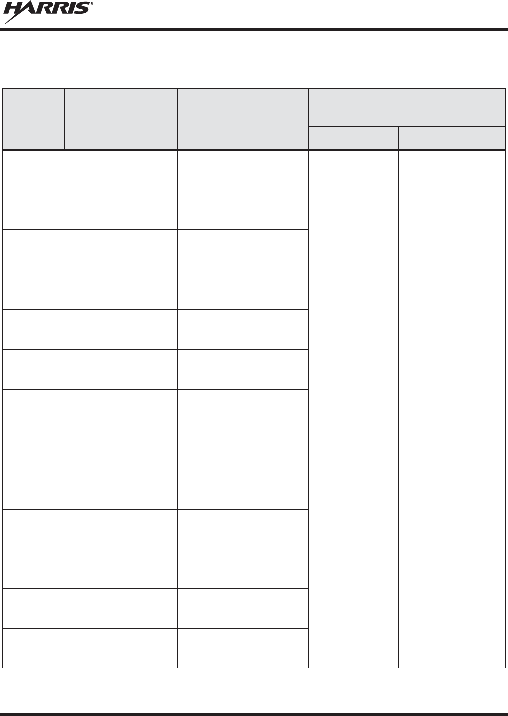
MM-014763-001, Rev. N
25
Tableau 2-3 : Distance latérale sécuritaire minimale recommandée d’une antenne de transmissio
n
branchée sur une radio mobile
RF
BAND
NUMÉRO DE PIÈCE DE
L’ÉLÉMENT DE
L’ANTENNE
DESCRIPTION DE
L’ANTENNE
DISTANCE MINIMALE RECOMMANDÉE DE
L
’
ANTENNE DE TRANSMISSION POUR LE
CORPS HUMAIN
ENVIRONNEMENT
CONTRÔLÉ
ENVIRONNEMENT NON
CONTRÔLÉ
UHF-L
AN
-125001-
007 (monture)
avec
AN
-225003-
004 (élément)
378 à 430
MHz; montage
magnétique; gain de 0
dBd;
profil bas
54 cm
(21,3 po) 120 cm
(47,2 po)
UHF-L
AN
-125001-
001 (monture)
avec
AN
-225004-
001 (élément)
450 to 512
MHz; antenne de
toit standard; gain de 0
dBd
51 Centimeters
(20 po) 114 Centimeters
(45 po)
UHF-L
AN
-125001-
001 (monture)
avec
AN
-225004-
004 (élément)
450 to 512
MHz; antenne de
toit standard; gain de 0
dBd;
profil bas
UHF-L
AN
-125001-
003 (monture)
avec
AN
-225004-001 (
élément)
450 to 512
MHz;
antenne de
toit épais de; gain de 0
dBd
UHF-L
AN
-125001-
003 (monture)
avec AN-225004-
004
(élément)
450 to 512
MHz;
antenne de
toit épais de; gain de 0
dBd;
profil bas
UHF-L
AN
-125001-
005 (monture)
avec
AN
-225004-
001 (élément)
450 to 512 MHz;
combo
antenne de toit épais et; gain
de 0 dBd
UHF-L
AN
-125001-
005 (monture)
avec
AN
-225004-
004 (élément)
450 to 512 MHz;
combo
antenne de toit épais et; gain
de 0 dBd; profil bas
UHF-L
AN
-125001-
007 (monture)
avec
AN
-225004-001 (
élément)
450 to 512 MHz;
montage
magnétique; gain de 0
dBd
UHF-L
AN
-125001-
007 (monture)
avec
AN
-225004-
004 (élément)
450 to 512 MHz;
montage
magnétique; gain de 0
dBd;
profil bas
UHF-L
AN102800V1
(n’est plus vendu)
136 à 941
MHz, ¼ -
longueur
d’onde*; antenne de toit toit
standard; gain de 0 dBd
UHF-H
AN
-125001-
001 (monture)
avec
AN
-225003-
001 (élément)
378 à 430
MHz; antenne de
toit standard; gain de 0
dBd
54 cm
(21,3 po) 120 cm
(47,2 po)
UHF-H
AN
-125001-001 (
monture)
avec
AN
-225003-
004 (élément)
378 à 430
MHz; antenne de
toit standard; gain de 0
dBd;
profil bas
UHF-H
AN
-125001-
003 (monture)
avec
AN
-225003-
001 (élément)
378 à 430
MHz; antenne de
toit épais de; gain de 0
dBd
(Suite du tableau à la page suivante)

MM-014763-001, Rev. N
26
Tableau 2-3 : Distance latérale sécuritaire minimale recommandée d’une antenne de transmissio
n
branchée sur une radio mobile
RF
BAND
NUMÉRO DE PIÈCE DE
L’ÉLÉMENT DE
L’ANTENNE
DESCRIPTION DE
L’ANTENNE
DISTANCE MINIMALE RECOMMANDÉE DE
L
’
ANTENNE DE TRANSMISSION POUR LE
CORPS HUMAIN
ENVIRONNEMENT
CONTRÔLÉ
ENVIRONNEMENT NON
CONTRÔLÉ
UHF-H
AN
-125001-
003 (monture)
avec AN-225003-
004
(élément)
378 à 430
MHz; antenne de
toit épais de; gain de 0
dBd;
profil bas
54 cm
(21,3 po) 120 cm
(47,2 po)
UHF-H
AN
-125001-
005 (monture)
avec
AN
-225003-
001 (élément)
378 à 430
MHz; combo
antenne de toit épais et; gain
de 0 dBd
UHF-H
AN
-125001-
005 (monture)
avec
AN
-225003-
004 (élément)
378 à 430
MHz; combo
antenne de toit épais et; gain
de 0 dBd; profil bas
UHF-H
AN
-125001-
007 (monture)
avec
AN
-225003-
001 (élément)
378 à 430 MHz;
montage
magnétique; gain de 0
dBd
UHF-H
AN
-125001-
007 (monture)
avec
AN
-225003-
004 (élément)
378 à 430
MHz; montage
magnétique; gain de 0
dBd;
profil bas
UHF-H
AN
-125001-
001 (monture)
avec
AN
-225004-
001 (élément)
450 to 512
MHz; antenne de
toit standard; gain de 0
dBd
51 Centimeters
(20 po) 114 Centimeters
(45 po)
UHF-H
AN
-125001-
001 (monture)
avec
AN
-225004-
004 (élément)
450 to 512
MHz; antenne de
toit standard; gain de 0
dBd;
profil bas
UHF-H
AN
-125001-
003 (monture)
avec AN-225004-
001
(élément)
450 to 512
MHz;
antenne de
toit épais de; gain de 0
dBd
UHF-H
AN
-125001-
003 (monture)
avec
AN
-225004-
004 (élément)
450 to 512
MHz;
antenne de
toit épais de; gain de 0
dBd;
profil bas
UHF-H
AN
-125001-
005 (monture)
avec
AN
-225004-001 (
élément)
450 to 512 MHz;
combo
antenne de toit épais et; gain
de 0 dBd
UHF-H
AN
-125001-
005 (monture)
avec
AN
-225004-
004 (élément)
450 to 512 MHz;
combo
antenne de toit épais et; gain
de 0 dBd; profil bas
UHF-H
AN
-125001-
007 (monture)
avec AN-225004-
001
(élément)
450 to 512 MHz;
montage
magnétique; gain de 0
dBd
UHF-H
AN
-125001-
007 (monture)
avec
AN
-225004-
004 (élément)
450 to 512 MHz;
montage
magnétique; gain de 0
dBd;
profil bas
(Suite du tableau à la page suivante)

MM-014763-001, Rev. N
27
Tableau 2-3 : Distance latérale sécuritaire minimale recommandée d’une antenne de transmissio
n
branchée sur une radio mobile
RF
BAND
NUMÉRO DE PIÈCE DE
L’ÉLÉMENT DE
L’ANTENNE
DESCRIPTION DE
L’ANTENNE
DISTANCE MINIMALE RECOMMANDÉE DE
L
’
ANTENNE DE TRANSMISSION POUR LE
CORPS HUMAIN
ENVIRONNEMENT
CONTRÔLÉ
ENVIRONNEMENT NON
CONTRÔLÉ
UHF-H
AN102800V1
(n’est plus vendu)
136 à 941
MHz, ¼ -
longueur
d’onde*; antenne de toit toit
standard; gain de 0 dBd
51 Centimeters
(20 po) 114 Centimeters
(45 po)
700/800
MHz
AN
-125001-
002 (monture)
avec
AN
-225001-
001 (élément)
Antenne de toit standard de
700/800
MHz; gain de 3
dBd
25 cm
(9,8 po) 55 cm
(21,7 po)
700/800
MHz
AN
-125001-
002 (monture)
avec
AN
-225001-
002 (élément)
Antenne de toit standard de
700/800 MHz; point
d’alimentation surélevé, gain
de 3 dBd
700/800
MHz
AN
-125001-
002 (monture)
avec
AN
-225001-003
(élément)
Antenne de toit standard de
700/800 MHz; point
d’alimentation surélevé, gain
de 3
dBd sans plan de sol
700/800
MHz
AN
-125001-
002 (monture)
avec
AN
-225001-
004 (élément)
Antenne de toit standard de
700/800
MHz; gain de 2
dBd à
profil bas
700/800
MHz
AN
-125001-
002 (monture)
avec
AN
-225001-
005 (élément)
Antenne de toit standard de
700/800
MHz; gain de 5
dBd
30 cm
(11,8 po) 60 cm
(23,6 po)
700/800
MHz
AN
-125001-
004 (monture)
avec
AN
-225001-
001 (élément)
Antenne de toit épais de
700/800
MHz; gain de 3
dBd
25 cm
(9,8 po) 55 cm
(21,7 po)
700/800
MHz
AN
-125001-
004 (monture)
avec
AN
-225001-
002 (élément)
Antenne de toit épais de
700/800 MHz; point
d’alimentation surélevé, gain
de 3 dBd
700/800
MHz
AN
-125001-
004 (monture)
avec
AN
-225001-
003 (élément)
Antenne de toit épais de
700/800 MHz; point
d’alimentation surélevé, gain
de 3
dBd sans plan de sol
700/800
MHz
AN
-125001-
004 (monture)
avec AN-225001-
004
(élément)
Antenne de toit épais de
700/800
MHz; gain de 2
dBd à
profil bas
700/800
MHz
AN
-125001-
004 (monture)
avec
AN
-225001-
005 (élément)
Antenne de toit
épais de
700/800
MHz; gain de 5
dBd
30 cm
(11,8 po) 60 cm
(23,6 po)
700/800
MHz
AN
-125001-
006 (monture)
avec
AN
-225001-001
(élément)
Combo antenne de toit et GPS
de 700/800
MHz; gain de
3 dBd / 5,15 dBi
25 cm
(9,8 po) 55 cm
(21,7 po)
(Suite du tableau à la page suivante)

MM-014763-001, Rev. N
28
Tableau 2-3 : Distance latérale sécuritaire minimale recommandée d’une antenne de transmissio
n
branchée sur une radio mobile
RF
BAND
NUMÉRO DE PIÈCE DE
L’ÉLÉMENT DE
L’ANTENNE
DESCRIPTION DE
L’ANTENNE
DISTANCE MINIMALE RECOMMANDÉE DE
L
’
ANTENNE DE TRANSMISSION POUR LE
CORPS HUMAIN
ENVIRONNEMENT
CONTRÔLÉ
ENVIRONNEMENT NON
CONTRÔLÉ
700/800
MHz
AN
-125001-
006 (monture)
avec
AN
-225001-
002 (élément)
Combo antenne de toit épais
et GPS de 700/800
MHz; point
d’alimentation surélevé, gain
de 3 dBd
25 cm
(9,8 po) 55 cm
(21,7 po)
700/800
MHz
AN
-125001-
006 (monture)
avec AN-225001-
003
(élément)
Combo antenne de toit et GPS
700/800 MHz; point
d’alimentation surélevé, gain
de 3
dBd sans plan de sol
700/800
MHz
AN
-125001-
006 (monture)
avec
AN
-225001-
004 (élément)
Combo antenne de toit et GPS
de 700/800
MHz; gain de
2 dBd à profil bas
700/800
MHz
AN
-125001-
006 (monture)
avec
AN
-225001-
005 (élément)
Combo antenne de toit et GPS
de 700/800
MHz; gain de
5 dBd / 7,15 dBi
32 cm
(12,6 po) 72 cm
(28,3 po)
700/800
MHz
AN
-125001-
008 (monture)
avec AN-225001-
001
(élément)
Antenne magnétique de
700/800
MHz; gain de 3
dBd
25 cm
(9,8 po) 55 cm
(21,7 po)
700/800
MHz
AN
-125001-
008 (monture)
avec
AN
-225001-
002 (élément)
Antenne magnétique de
700/800 MHz; point
d’alimentation surélevé, gain
de 3 dBd
700/800
MHz
AN
-125001-
008 (monture)
avec AN-225001-
003
(élément)
Antenne magnétique de
700/800 MHz; point
d’alimentation surélevé, gain
de 3
dBd sans plan de sol
700/800
MHz
AN
-125001-
008 (monture)
avec
AN
-225001-
004 (élément)
Antenne magnétique de
700/800
MHz; gain de 2
dBd à
profil bas
700/800
MHz
AN
-125001-
008 (monture)
avec
AN
-225001-
005 (élément)
Antenne à monture
magnétique de 700/800
MHz;
gain de 5 dBd
30 cm
(11,8 po) 60 cm
(23,6 po)
700/800
MHz
AN102800V1
(n’est plus vendu)
136 à 941
MHz, ¼ -
longueur
d’onde*; antenne de toit toit
standard; gain de 0 dBd
25 cm
(9,8 po) 55 cm
(21,7 po)
900
MHz
AN-125001-002 (monture)
avec
AN-225005-001 (élément)
Antenne de toit standard de
900 MHz; gain de 3 dBd
51 cm
(20,1 po)
113 centimeters
(44,5 po)
900
MHz
AN-125001-002 (monture)
avec
AN-225005-002 (élément)
Antenne de toit standard de
9
00 MHz; point
d’alimentation
surélevé, gain de 3 dBd
900
MHz
AN
-125001-002
(monture)
avec
AN
-225005-003
(élément)
Antenne de toit standard de
9
00 MHz;
point d’alimentation
surélevé, gain de 3
dBd sans
plan de sol
51 cm
(20,1 po)
113 centimeters
(44,5 po)
(Suite du tableau à la page suivante)

MM-014763-001, Rev. N
29
Tableau 2-3 : Distance latérale sécuritaire minimale recommandée d’une antenne de transmissio
n
branchée sur une radio mobile
RF
BAND
NUMÉRO DE PIÈCE DE
L’ÉLÉMENT DE
L’ANTENNE
DESCRIPTION DE
L’ANTENNE
DISTANCE MINIMALE RECOMMANDÉE DE
L
’
ANTENNE DE TRANSMISSION POUR LE
CORPS HUMAIN
ENVIRONNEMENT
CONTRÔLÉ
ENVIRONNEMENT NON
CONTRÔLÉ
900
MHz
AN-125001-002 (monture)
avec
AN-225005-004 (élément)
Antenne de toit standard de
900 MHz; gain de 2
dBd à
profil bas
900
MHz
AN
-125001-002
(monture)
avec
AN
-225006-001
(élément)
132 à 960 MHz ; ¼ - longueur
d’onde;
antenne de toit
standard;gain de 0 dBd
;
syntonisé sur place
900
MHz
AN-125001-004 (monture)
avec
AN-225005-001 (élément)
Antenne de toit épais de
900 MHz; gain de 3 dBd
900
MHz
AN-125001-004 (monture)
avec
AN-225005-002 (element)
Antenne de toit épais de
9
00 MHz;
point d’alimentation
surélevé, gain de 3 dBd
900
MHz
AN
-125001-004
(monture)
avec
AN
-225005-003
(élément)
Antenne de toit épais de
9
00 MHz;
point d’alimentation
surélevé, gain de 3
dBd sans
plan de sol
900
MHz
AN-125001-004 (monture)
avec
AN-225005-004 (élément)
Antenne de toit épais de
900 MHz; gain de 2
dBd à
profil bas
900
MHz
AN-125001-004 (monture)
avec
AN-225006-001 (élément)
132 à 960 MHz, ¼ - longueur
d’onde;
pour toit épais;
gain de
0 dBd; syntonisé sur place
900
MHz
AN-125001-006 (monture)
avec
AN-225005-001 (élément)
Combo antenne de toit et GPS
de
900 MHz; gain de 3
dBd /
5,15 dBi
51 centimeters
(20,1 po)
113 centimeters
(44,5 po)
900
MHz
AN
-125001-006
(monture)
avec
AN
-225005-002
(élément)
Combo antenne de toit épais
et GPS de 900 MHz;
point
d’alimentation surélevé, gain
de 3 dBd
900
MHz
AN
-125001-006
(monture)
avec
AN
-225005-003
(élément)
Combo antenne de toit et GPS
9
00 MHz;
point d’alimentation
surélevé, gain de 3
dBd sans
plan de sol
900
MHz
AN-125001-006 (mount)
with
AN-225005-004 (élément)
Combo antenne de toit et GPS
de 700/800 MHz;
gain de
2 dBd à profil bas
900
MHz
AN
-125001-006
(monture)
avec
AN
-225006-001
(élément)
132 à 960 MHz, ¼ - longueur
d’onde;
support sur le toit à
combo; gain de 0
dBd; champ
syntonisé
(Suite du tableau à la page suivante)

MM-014763-001, Rev. N
30
Tableau 2-3 : Distance latérale sécuritaire minimale recommandée d’une antenne de transmissio
n
branchée sur une radio mobile
RF
BAND
NUMÉRO DE PIÈCE DE
L’ÉLÉMENT DE
L’ANTENNE
DESCRIPTION DE
L’ANTENNE
DISTANCE MINIMALE RECOMMANDÉE DE
L
’
ANTENNE DE TRANSMISSION POUR LE
CORPS HUMAIN
ENVIRONNEMENT
CONTRÔLÉ
ENVIRONNEMENT NON
CONTRÔLÉ
900
MHz
AN-125001-008 (monture)
avec
AN-225005-001 (element)
Antenne magnétique de
900 MHz; gain de 3 dBd
51 centimeters
(20,1 po)
113 centimeters
(44,5 po)
900
MHz
AN-125001-008 (monture)
avec
AN-225005-002 (élément)
Antenne magnétique de
9
00 MHz;
point d’alimentation
surélevé, gain de 3 dBd
900
MHz
AN
-125001-008
(monture)
avec
AN
-225005-003
(élément)
Antenne magnétique de
700/800 MHz; point
d’alimentation surélevé, gain
de 3 dBd sans plan de sol
900
MHz
AN-125001-008 (monture)
avec
AN-225005-004 (élément)
Antenne magnétique de
900 MHz; gain de 2
dBd à
profil bas
900
MHz
AN
-125001-008
(monture)
avec
AN
-225006-001
(élément)
132 à 960 MHz, ¼ - longueur
d’onde;
antenne de toit à
monture
magnétique;
gain de
0 dBd; syntonisé sur plac
900
MHz
Astron NMO9000
890 to 950 MHz
NMO
-Mount Radome 3
dBi
Gain
40 centimeters
(15,8 po) 88 centimeters
(34,6 po)
900 MH
AN102800V1
(n’est plus vendu)
136 à 941 MHz, ¼ - longueur
d’onde*; antenne de toit
toit
standard; gain de 0 dBd
25 cm
(9,8 po) 55 cm
(21,7 po)
* L'élément mené des pièces AN-225006-001 et AN102800V1 doit être ajusté à une longueur adéquate pour minimiser
le ROS du système d'antenne.
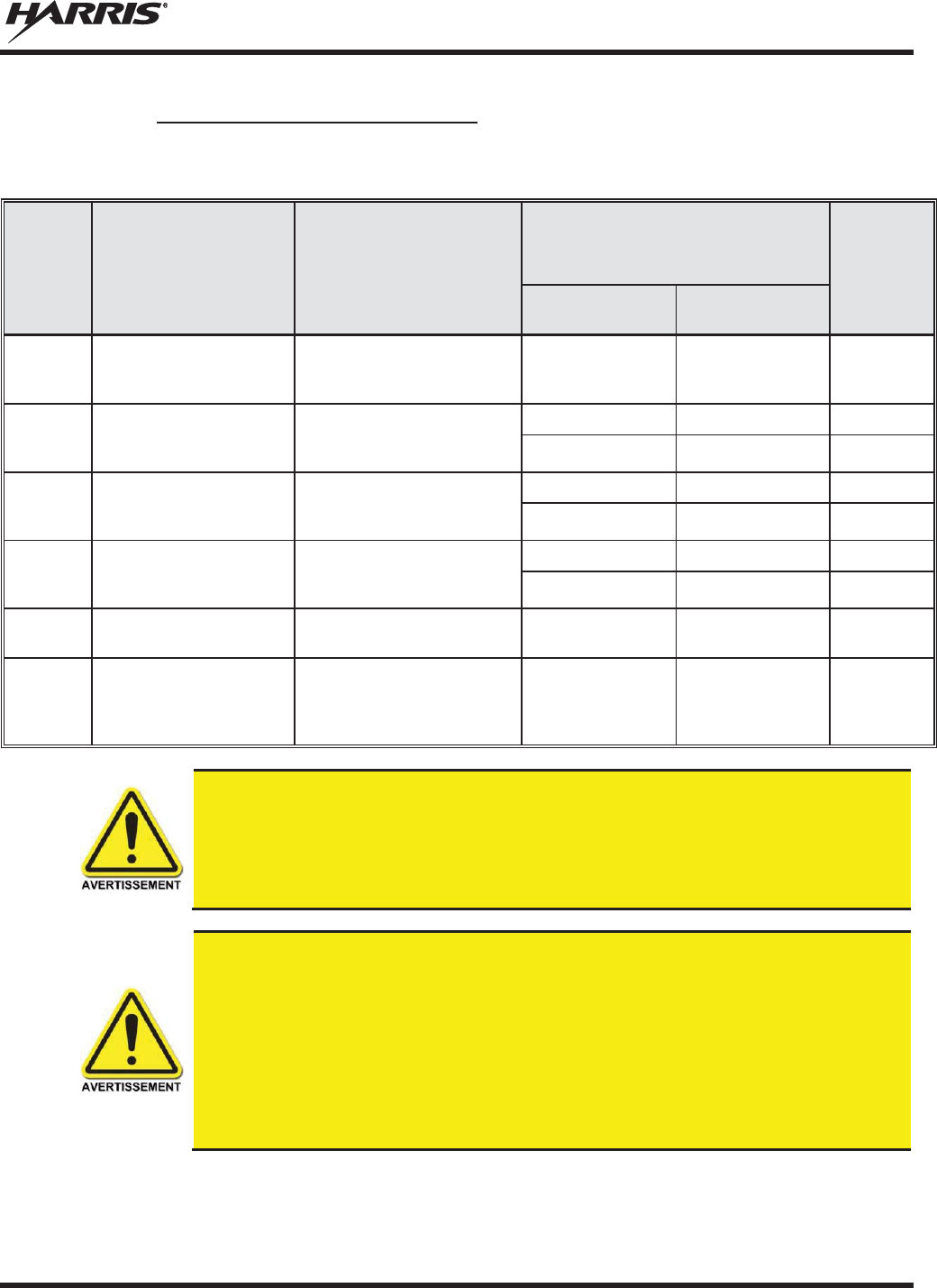
MM-014763-001, Rev. N
31
2.5.4 Monté Antennes (Motocyclette)
Tableau 2-4: Distance latérale sécuritaire minimale recommandée d’une antenne de transmission
branchée sur une radio Motocyclette
RF
BAND
NUMÉRO DE PIÈCE DE
L’ÉLÉMENT DE
L’ANTENNE
DESCRIPTION DE
L’ANTENNE
DISTANCE MINIMALE
RECOMMANDÉE DE L
’
ANTENNE DE
TRANSMISSION POUR LE CORPS
HUMAIN
MAX.
TX
PUISSANCE
(Watts)
ENVIRONNEMENT
CONTRÔLÉ
ENVIRONNEMENT
NON CONTRÔLÉ
VHF
LE-
OM150K.125/TNC
136 to 174 MHz
motocyclette-
monture; gain
de 2.5 dBd 53 cm 118 cm 20
VHF
AN
-125001-
005 (monture)
avec
AN
-225002-
004 (élément)
136 to 174 MHz; combo
antenne de toit épais e; sans
plan de sol;gain de 2.4
dBd
50 cm — 18
— 50 cm 3.6
UHF- L
AN
-125001-
005 (monture)
avec
AN
-225003-
005 (élément)
378 à 430 MHz; combo
antenne de toit épais e; sans
plan de sol;gain de 0 dBd;
50 cm — 43
— 50 8.5
UHF - H
AN
-125001-
005 (monture)
avec
AN
-225004-
005 (élément)
450 à 505 MHz; combo
antenne de toit épais et; sans
plan de sol; gain de 0
dBd
50 cm — 47
— 50 cm 9.5
800 MHz
LE
-
OM806HDBKTNCDS
800 MHz -
monture; gain de
3.5 dBd 28 cm 72 cm 20
700 or 800
MHz
AN
-125001-
006 (monture)
avec
AN
-225001-
003 (élément)
700/800 MHz; combo
antenne de toit et GPS; point
d’alimentation surélevé, gain
de 3 dBd sans plan de sol
50 cm 50 cm 20
Une
radio utilisé dans une installation de motocyclette doit être configuré avec
un
niveau de puissance
de sortie d'émission inférieur ou égal au maximum TX
Puissance
(Watts
) spécifications énumérées dans le Tableau 2-4 pour la bande de
fréquence
respective
et l'élément antenne / antenne. Reportez-vous au manuel d'installation
de la
radio
pour des informations supplémentaires.
Quand un kit d'installation de moto plus tard, la conception est employée (qui utilise
élément d'antenne UN AN-225001-003 ou 225002-004), le câble coaxial entre la radio
et la base de la monture d'antenne ne peut pas être plus courte que 44 pouces (111,8
cm) . Reportez-vous au manuel d'installation de la radio pour des informations
supplémentaires.
Une radio destinés à une installation non-moto ne doit pas être utilisé dans une
installation de moto sauf se il est reprogrammé par les procédures présentées dans le
Manuel d'installation de la radio.

MM-014763-001, Rev. N
32
2.6 RENSEIGNEMENTS SUR LA FORMATION SUR LA SANTÉ ET LA
SÉCURITÉ AU TRAVAIL
S’assurer que l’exposition physique à l’énergie électromagnétique des RF se situe dans les limites
acceptables de la FCC pour l’utilisation professionnelle. Toujours se conformer aux directives de base
suivantes:
x Le bouton de microphone doit être abaissé seulement lorsque l’on souhaite envoyer un message
vocal.
x La radio doit être utilisée seulement pour les communications nécessaires liées au travail.
x La radio doit être utilisée seulement par du personnel autorisé et formé. Elle ne doit jamais être
utilisée par des enfants.
x Ne tentez pas d’apporter une modification non autorisée à la radio. Des changements ou des
modifications à la radio peuvent causer une interférence nocive ou entraîner un dépassement des
limites d’exposition aux RF de la FCC. Seul le personnel qualifié doit utiliser la radio.
x Utilisez toujours seulement des accessoires autorisés (antennes, haut-parleurs/micros, etc.).
L’utilisation d’accessoires non autorisés peut entraîner un dépassement des exigences de conformité
pour une exposition aux RF de la FCC.
Les renseignements donnés ci-dessus donnent à l’utilisateur les renseignements nécessaires pour le
sensibiliser à l’exposition aux RF et sur ce qu’il faut faire pour s’assurer que cette radio fonctionne dans
les limites d’exposition de la FCC de cette radio.
2.7 DANGERS COURANTS
L'utilisateur de toute radio mobile doit être informé des dangers courants aux
transmissions par des radios d
e véhicules.
Les dangers éventuels comprennent,
sans toutefois s'y limiter
:
x Atmosphères explosives – De la même manière qu'il est dangereux de faire le plein d'essence d'un
véhicule dont le moteur est en marche, s'assurer que la radio est éteinte (position OFF) avant de faire
le plein d'essence. NE PAS transporter de conteneurs de carburant dans le coffre d'un véhicule si la
radio est montée dans celui-ci.
Les zones avec une atmosphère potentiellement explosive sont souvent, mais pas toujours, clairement
signalés. Éteindre la radio (position OFF) dans toutes les zones avec une atmosphère potentiellement
explosive. Il est rare, mais pas impossible, que la radio ou ses accessoires génère des étincelles.
x Interférences avec les systèmes électroniques de véhicules – Les systèmes électroniques à injection
de carburant, les systèmes électroniques de freinage antidérapage, les systèmes électroniques de
régulateur de vitesse, etc., sont des systèmes pouvant mal fonctionner en raison d'une protection
insuffisante contre l'énergie RF présente lors des transmissions. Si le véhicule est équipe de tels
systèmes, consulter le concessionnaire pour obtenir des informations sur la marque du véhicule et
déterminer si de tels circuits électroniques fonctionnent normalement lorsque le radio émet.
x Détonateurs électroniques – Afin d'éviter toute explosion accidentelle des détonateurs électriques,
NE PAS UTILISER les radios émetteur-récepteur à moins de 305 mètres (1 000 pieds) d'une
opération de dynamitage. Respecter toujours les signes d’extinction des radios émetteur-récepteur
affichés dans les endroits où les détonateurs électriques sont utilisés. (norme OSHA : 1926.900)

MM-014763-001, Rev. N
33
x Énergie des fréquences radio – Pour prévenir toute brûlure ou toute blessure physique connexe
causée par l'énergie des fréquences radio, ne pas faire fonctionner l'émetteur lorsqu'une personne à
l'extérieur du véhicule est située en deçà de la distance minimale sécuritaire de l'antenne, comme
stipulé à la Section 2.5.
x Véhicules alimentés au gaz de pétrole liquéfié (GLP) – L'installation de radios mobiles dans des
véhicules alimentés au gaz de pétrole liquéfié avec un réservoir GLP dans le coffre ou dans tout autre
espace scellé à l'intérieur du véhicule doit être conforme à la norme NFPA 58 de la National Fire
Protection Association. Exigences :
¾ L'emplacement qui abrite la radio doit être isolé et scellé de l'emplacement contenant le réservoir
de GLP et ses raccords.
¾ Des raccords de remplissage extérieurs doivent être utilisés pour le réservoir de GLP.
¾ Le réservoir de GLP doit être pourvu d'une évacuation vers l'extérieur du véhicule
x Véhicules équipés de coussins gonflables – Pour la protection du conducteur et celle des passagers,
éviter d'installer les têtes de commandes de la radio (ou tout autre composant) au-dessus ou à
proximité des zones de déploiement de ces coussins gonflables. Outre les coussins gonflables avant
du conducteur et du passager, certains véhicules peuvent aussi être équipés de coussins gonflables
latéraux. Pour la sécurité des occupants, vérifier l'emplacement de tous les coussins gonflables dans le
véhicule avant d'installer équipement radio.
2.8 RECOMMANDATIONS POUR UNE CONDUITE SÉCURITAIRE
Recommandations principales de l'American Automobile Association (AAA) pour une conduite en toute
sécurité :
x Lire la documentation sur la sécurité d'utilisation de la radio.
x Garder les deux mains sur le volant et ranger le microphone dans son support durant la conduite du
véhicule.
x Effectuer un appel seulement lorsque le véhicule est à l'arrêt.
x Si un appel doit être effectué alors que le véhicule est en mouvement, conduire dans la voie la plus
lente. Les conversations doivent être brèves.
x Si une conversation nécessite la prise de notes ou exige une réflexion plus approfondie, arrêter le
véhicule dans un endroit sûr et poursuivre l'appel.
x Toujours utiliser une radio mobile avec prudence.
2.9 RÈGLES ET RÉGLEMENTATIONS D'UTILISATION
Les systèmes de radio émetteur-récepteur doivent être utilisés conformément aux règles et
réglementations du gouvernement local, régional ou national.
Aux États-Unis, la radio mobile M5300 doit être utilisée conformément aux règles et réglementations de
la Commission fédérale des communications (FCC). L'opérateur d'une radio émetteur-récepteur doit être
pleinement familiarisé avec les règles qui s'appliquent au fonctionnement d'une radio de ce type. Le
respect de ces règles aide à éliminer la confusion, garantit une utilisation hautement efficace des canaux
radio existants et assure le bon fonctionnement du réseau radio.
Rappels des règles à suivre lors de l'utilisation d'une radio émetteur-récepteur :
x L'interruption de messages de détresse ou d'urgence constitue une violation des règles de la FCC. Le
fonctionnement de la radio est similaire au fonctionnement d'un téléphone « connexion multipoint ».
MM-014763-001, Rev. N
34
Par conséquent, toujours écouter avant d'émettre afin de s'assurer que le canal est libre. Les appels
d'urgence sont prioritaires sur tous les autres messages. Si un message d'urgence est en cours de
transmission (pour signaler un incendie ou demander de l'aide à la suite d'un accident, par exemple),
ne pas émettre de messages sauf pour venir en aide.
x La loi fédérale interdit l'utilisation d'un langage obscène ou blasphématoire.
x La loi interdit l'envoi de faux indicatifs d'appel ou de faux messages de détresse ou d'urgence. La
FCC exige que vos conversations soient brèves et s'en tiennent au sujet de l'appel. Pour gagner du
temps, utiliser autant que possible des messages codés.
x L'utilisation de la radio pour l'envoi de messages personnels (sauf en cas d'urgence) constitue une
violation des règles de la FCC. Envoyer des messages essentiels uniquement.
x La loi fédérale interdit la répétition ou la diffusion de toute information entendue via les
communications radio. Les conversations entre les utilisateurs qui partagent un même canal doivent
être traitées comme des messages confidentiels.
x La FCC exige que les utilisateurs s'identifient à certains moments au moyen de leur indicatif d'appel.
Se référer aux règles qui s'appliquent au type particulier d'activités pour la bonne procédure à suivre.
x Aucune modification ou aucun ajustement ne doit être fait à l'équipement, sauf par un technicien
électronique autorisé et certifié.
En vertu de la loi des États
-Unis, l'utilisation d'un émetteur radio sans licence
sur le
territoire américain est punissable d'une amende d'un maximum de 10
000
$, d'un
emprisonnement de deux (2) ans au maximum, ou les deux.
MM-014763-001, Rev. N
35
3 OPTIONS AND ACCESSORIES
A complete list of Options and Accessories approved for use with the M5300, M7300, and XG-75M
mobile radios can be found online in the applicable Operator’s Manual at
http://pspc.harris.com/Products/Radios.aspx. Also reference the Products and Services Catalog for all
available options and accessories, including those items that do not adversely affect the RF energy
exposure.
4 RELATED PUBLICATIONS
R
adio installation and maintenance manuals are available on-line via Tech-
Link or as a
printed manual.
Please contact the Harris Customer Care center for assistance.
Along with this Product Safety Manual, Quick Guides (for radio operators) are included with each mobile
radio equipment package when the package ships from the factory. The Operator’s Manual and the Quick
Guides are also available on-line at http://pspc.harris.com/Products/Radios.aspx without a login. All
M5300, M7300, and XG-75M related mobile radio publications (installation manuals, maintenance
manuals, etc.) can be obtained from www.pspc.harris.com via an Information Center login (i.e., a user
name and password are required). The publications are in Tech-Link’s Technical Manual Library.
NOTE

MM-014763-001, Rev. N
36
5 CUSTOMER SERVICE
5.1 CUSTOMER CARE
If any part of the system equipment is damaged on arrival, contact the shipper to conduct an inspection
and prepare a damage report. Save the shipping container and all packing materials until the inspection
and the damage report are completed. In addition, contact the Customer Care center to make
arrangements for replacement equipment. Do not return any part of the shipment until you receive
detailed instructions from a Harris representative.
Contact the Customer Care center at http://www.pspc.harris.com/CustomerService or:
North America:
Phone Number: 1-800-368-3277
Fax Number: 1-321-409-4393
E-mail: PSPC_CustomerFocus@harris.com
International:
Phone Number: 1-434-455-6403
Fax Number: 1-321-409-4394
E-mail: PSPC_InternationalCustomerFocus@harris.com
5.2 TECHNICAL ASSISTANCE
The Technical Assistance Center’s (TAC) resources are available to help with overall system operation,
maintenance, upgrades, and product support. TAC is the point of contact when answers are needed to
technical questions.
Product specialists, with detailed knowledge of product operation, maintenance, and repair provide
technical support via a toll-free (in North America) telephone number. Support is also available through
mail, fax, and e-mail.
For more information about technical assistance services, contact your sales representative, or contact the
Technical Assistance Center directly at:
North America: 1-800-528-7711
International: 1-434-385-2400
Fax Number: 1-434-455-6712
E-mail: PSPC_tac@harris.com
5.3 Tech-Link
Tech-Link is a one stop link to Technical Documentation (downloadable PDFs) - Software Revisions -
Feature Encryption - pictorials of parts and accessories - and other information pertaining to our products.
It also contains information that will enhance your service efforts -- 24 hours a day, 7 days a week.
For more information about this and other Harris PSPC products, check out our Tech-Link service at:
https://premier.pspc.harris.com/

MM-014763-001, Rev. N
37
6 WARRANTY REGISTRATION
Please register this product within 10 days of purchase. Registration validates the warranty coverage, and
enables Harris to contact you in case of any safety notifications issued for this product.
Registration can be made on-line at the Customer Care center webpage:
http://www.pspc.harris.com/Service/Customerservice.aspx.
While on the webpage, please review the applicable battery and/or product warranty literature.

Public Safety and Professional Communications | www.pspc.harris.com
221 Jefferson Ridge Parkway | Lynchburg, VA USA 24501 | 1-800-528-
7711