HARRIS TR-0134-E XG-15P 700/800 MHz portable radio User Manual
HARRIS CORPORATION XG-15P 700/800 MHz portable radio
HARRIS >
User Manual

Rhein Tech Laboratories, Inc. Client: Harris Corporation
360 Herndon Parkway EUT: XG-15P 700/800 MHz
Suite 1400 ID’s: OWDTR-0134-E/3636B-0134
Herndon, VA20170 Standards: FCC Part 90
http://www.rheintech.com Report #: 2015011
Appendix M: Manuals
Please refer to the following pages for the Operators Manual and the Product Safety Manual.
Operator’s Manual
14221-1450-2000
Mar/15
XG-15P Series
Portable Radio

14221-1450-2000
2
REV
DATE
REASON FOR REVISION
-
Mar/15
Initial release.
Harris Corporation, Public Safety and Professional Communications (PSPC) Business continually evaluates its technical publications for
completeness, technical accuracy, and organization. You can assist in this process by submitting your comments and suggestions to the
following:
Harris Corporation fax your comments to: 1-434-455-6851
PSPC Business or
Technical Publications e-mail us at: PSPC_TechPubs@harris.com
221 Jefferson Ridge Parkway
Lynchburg, VA 24501 ACKNOWLEDGEMENTS
The software contained in this device is copyrighted by Harris Corporation Unpublished rights are reserved under the copyright laws of the
United States.
This device is made under license under one or more of the following US patents: 4,590,473; 4,636,791; 5,148,482; 5,185,796; 5,271,017;
5,377,229; 4,716,407; 4,972,460; 5,502,767; 5,146,497; 5,164,986; 5,185,795; 5,226,084; 5,247,579; ; 5,491,772; 5,517,511; 5,630,011;
5,649,050; 5,701,390; 5,715,365; 5,754,974; 5,826,222; 5,870,405; 6,161,089; and 6,199,037 B1. DVSI claims certain rights, including
patent rights under aforementioned U.S. patents, and under other U.S. and foreign patents and patents pending. Any use of this software or
technology requires a separate written license from DVSI.
CREDITS!
Harris Corporation, assuredcommunications, and VIDA are registered trademarks and ProScan and Failsoft are trademarks of Harris
Corporation.
RBRC and 1-800-8-BATTERY are registered trademarks of Rechargeable Battery Recycling Corporation.
AMBE is a registered trademark and IMBE, AMBE+, and AMBE+2 are trademarks of Digital Voice Systems, Inc.
TORX is a registered trademark of CAMCAR division of TEXTRON, Inc.
All other product and brand names are trademarks, registered trademarks, or service marks of their respective holders.
NOTICE!
The material contained herein is subject to U.S. export approval. No export or re-export is permitted without written approval from the U.S.
Government. Rated: EAR99; in accordance with U.S. Dept. of Commerce regulations 15CFR774, Export Administration Regulations.
Information and descriptions contained herein are the property of Harris Corporation. Such information and descriptions may not be copied
or reproduced by any means, or disseminated or distributed without the express prior written permission of Harris Corporation, PSPC
Business, 221 Jefferson Ridge Parkway, Lynchburg, VA 24501.
This manual covers Harris Corporation products manufactured and sold by Harris Corporation.
This product conforms to the European Union WEEE Directive 2012/19/EU. Do not dispose of this product in a public landfill. Take it to a
recycling center at the end of its life.
The voice coding technology embodied in this product is protected by intellectual property rights including patent rights, copyrights, and
trade secrets of Digital Voice Systems, Inc. The user of this technology is explicitly prohibited from attempting to decompile, reverse
engineer, or disassemble the Object Code, or in any other way convert the Object Code into human-readable form.
Repairs to this equipment should be made only by an authorized service technician or facility designated by the supplier. Changes or
modifications not expressly approved by Harris Corporation could void the user’s authority to operate the equipment.
This manual is published by Harris Corporation, without any warranty. Improvements and changes to this manual necessitated by
typographical errors, inaccuracies of current information, or improvements to programs and/or equipment, may be made by Harris
Corporation, at any time and without notice. Such changes will be incorporated into new editions of this manual. No part of this manual
may be reproduced or transmitted in any form or by any means, electronic or mechanical, including photocopying and recording, for any
purpose, without the express written permission of Harris Corporation.
Copyright © 2015 Harris Corporation. All rights reserved.

14221-1450-2000
3
TABLE OF CONTENTS
Page
1. REGULATORY AND SAFETY INFORMATION ............................................................................................. 6
1.1 SAFETY CONVENTIONS ........................................................................................................................ 6
1.2 SAFETY TRAINING INFORMATION ..................................................................................................... 6
1.2.1 RF Exposure Guidelines ............................................................................................................... 7
1.2.2 Electromagnetic Interference/Compatibility ................................................................................. 8
1.3 REGULATORY APPROVALS .................................................................................................................. 8
1.3.1 Part 15 ........................................................................................................................................... 8
1.3.2 Industry Canada ............................................................................................................................ 8
1.4 OPERATING TIPS ..................................................................................................................................... 8
1.5 EFFICIENT RADIO OPERATION ............................................................................................................ 9
1.5.1 Antenna Care and Replacement .................................................................................................... 9
1.5.2 Electronic Devices ........................................................................................................................ 9
1.5.3 Aircraft .......................................................................................................................................... 9
1.5.4 Electric Blasting Caps ................................................................................................................... 9
1.5.5 Potentially Explosive Atmospheres ............................................................................................ 10
2. RENSEIGNEMENTS SUR LA RÉGLEMENTATION ET SÉCURITÉ........................................................ 11
2.1 CONVENTIONS SUR LES SYMBOLES DE SÉCURITÉ ..................................................................... 11
2.2 RENSEIGNEMENTS SUR LA FORMATION SUR LA SÉCURITÉ ..................................................... 11
2.2.1 Directives sur l’exposition aux RF .............................................................................................. 12
2.2.2 Interférence/Compatibilité Électromagnétique ........................................................................... 13
2.3 INTERFÉRENCE DES RADIOFRÉQUENCES ...................................................................................... 13
2.3.1 Partie 15 de la FCC ..................................................................................................................... 13
2.3.2 Industrie Canada ......................................................................................................................... 13
2.4 CONSEILS D’UTILISATION .................................................................................................................. 13
2.4.1 Utilisation Efficace de la Radio .................................................................................................. 13
3. CLEANING .......................................................................................................................................................... 16
4. BATTERIES ......................................................................................................................................................... 17
4.1 BATTERY CARE/MAINTENANCE ....................................................................................................... 17
4.2 STORING LI-ION BATTERY PACKS ................................................................................................... 17
4.3 CHARGING BATTERY PACKS ............................................................................................................. 17
4.4 CHANGING THE BATTERY PACK ...................................................................................................... 18
4.4.1 Removing the Battery Pack ......................................................................................................... 18
4.4.2 Attaching the Battery Pack.......................................................................................................... 19
4.5 BATTERY DISPOSAL ............................................................................................................................ 19
5. INTRODUCTION ................................................................................................................................................ 20
5.1 WATER RESISTANCE............................................................................................................................ 21
5.2 UNIVERSAL DEVICE CONNECTOR ................................................................................................... 21
6. OPTIONS AND ACCESSORIES ....................................................................................................................... 22
7. OPERATION ........................................................................................................................................................ 25
7.1 TURNING ON THE RADIO .................................................................................................................... 25
7.2 CONTROLS .............................................................................................................................................. 25
7.2.1 Buttons, Knobs, and Switch ........................................................................................................ 26
7.2.2 Keypad ........................................................................................................................................ 26
7.3 DISPLAY .................................................................................................................................................. 27
7.4 RADIO STATUS ICONS ......................................................................................................................... 28
7.5 TRI-COLOR LED ..................................................................................................................................... 28
7.6 RADIO STATUS MESSAGES ................................................................................................................ 29
7.7 ERROR MESSAGES ................................................................................................................................ 29
7.8 ALERT TONES ........................................................................................................................................ 30

14221-1450-2000
4
TABLE OF CONTENTS
Page
7.9 VOICE ANNUNCIATION ....................................................................................................................... 30
7.10 SYSTEM/ZONE SELECTION ................................................................................................................. 30
7.11 GROUP/CHANNEL SELECTION ........................................................................................................... 31
7.12 MODIFY SCAN LIST .............................................................................................................................. 31
7.13 MENU ....................................................................................................................................................... 32
7.14 MENU ITEM SELECTION PROCESS .................................................................................................... 32
7.15 BACKLIGHT ON/OFF ............................................................................................................................. 34
7.16 CONTRAST ADJUST .............................................................................................................................. 34
7.17 DECLARING AN EMERGENCY ............................................................................................................ 35
7.18 LOCKING/UNLOCKING KEYPAD ....................................................................................................... 35
7.19 HIGH/LOW POWER ADJUSTMENT ..................................................................................................... 35
7.19.1 Using the Menu Button ............................................................................................................... 35
7.19.2 Using the Pre-Programmed Option Button ................................................................................. 35
7.20 ENCRYPTION .......................................................................................................................................... 35
7.20.1 Displaying the Currently Used Cryptographic Key Number....................................................... 36
7.20.2 Key Zero ...................................................................................................................................... 36
7.20.3 Receiving an Encrypted Call ....................................................................................................... 36
7.20.4 Transmitting an Encrypted Call................................................................................................... 36
7.20.5 Emergencies on Encrypted Group ............................................................................................... 37
7.21 SCAN OPERATION ................................................................................................................................. 37
7.21.1 Turning Scan On and Off ............................................................................................................ 37
7.21.2 Add Groups and Channels to a Scan List .................................................................................... 37
7.21.3 Deleting Groups from a Scan List ............................................................................................... 38
7.21.4 Nuisance Delete ........................................................................................................................... 38
7.22 SYSTEM SCAN (P25 TRUNKED) .......................................................................................................... 38
7.22.1 Wide Area System Scanning ....................................................................................................... 38
7.22.2 Priority System Scan ................................................................................................................... 39
7.22.3 ProScan ....................................................................................................................................... 39
7.23 EMERGENCY OPERATION ................................................................................................................... 39
7.23.1 Receiving an Emergency Call ..................................................................................................... 40
7.23.2 Declaring an Emergency Call ...................................................................................................... 40
7.24 MIXED SYSTEM ZONES........................................................................................................................ 40
7.25 CALLER ID .............................................................................................................................................. 40
7.26 STEALTH MODE ..................................................................................................................................... 41
7.27 INDIVIDUAL CALLS (P25 MODES) ..................................................................................................... 41
7.27.1 Receiving and Responding to an Individual Call ........................................................................ 42
7.27.2 Sending an Individual Call .......................................................................................................... 43
7.27.3 Call Storage Lists ........................................................................................................................ 44
7.28 TELEPHONE INTERCONNECT CALLS (P25 TRUNKED) ................................................................. 45
7.28.1 Receiving a Telephone Interconnect Call .................................................................................... 45
7.28.2 Sending a Telephone Interconnect Call ....................................................................................... 45
7.28.3 Dual-Tone Multi-Frequency: Overdial ........................................................................................ 46
7.29 PRE-STORING INDIVIDUAL AND TELEPHONE INTERCONNECT CALLS FROM THE
KEYPAD ................................................................................................................................................... 46
7.30 STATUS/MESSAGE OPERATION (P25 MODES) ................................................................................ 47
7.30.1 Status Operation .......................................................................................................................... 47
7.30.2 Message Operation ...................................................................................................................... 48
7.31 MACRO KEY OPERATION .................................................................................................................... 48
7.32 PORTABLE DATA .................................................................................................................................. 48
7.32.1 Displays ....................................................................................................................................... 48
7.32.2 DATA OFF Operation................................................................................................................. 49
7.32.3 DATA ON Operation .................................................................................................................. 49
7.32.4 Exiting Data Calls ....................................................................................................................... 49

14221-1450-2000
5
TABLE OF CONTENTS
Page
7.32.5 Scan Lockout Mode .................................................................................................................... 49
7.32.6 Data Lockout Mode .................................................................................................................... 50
7.33 TYPE 99 OPERATION (ANALOG CONVENTIONAL) ........................................................................ 50
7.33.1 Type 99 with or without Channel Guard ..................................................................................... 50
7.33.2 Resetting Type 99 after a Call ..................................................................................................... 50
7.33.3 Type 99 Disable after PTT .......................................................................................................... 50
7.34 AUDIO PLAYBACK ............................................................................................................................... 50
7.35 RADIO TEXTLINK OPERATION .......................................................................................................... 51
7.35.1 Send TextLink Messages ............................................................................................................ 51
7.35.2 View Received TextLink Messages ............................................................................................ 51
7.35.3 Delete TextLink Messages .......................................................................................................... 51
7.35.4 View the Current Time ............................................................................................................... 51
7.36 VIEW GPS INFORMATION ................................................................................................................... 51
7.37 CONTROL AND STATUS SERVICES ................................................................................................... 52
8. CUSTOMER SERVICE ...................................................................................................................................... 53
8.1 CUSTOMER CARE ................................................................................................................................. 53
8.2 TECHNICAL ASSISTANCE ................................................................................................................... 53
9. BASIC TROUBLESHOOTING .......................................................................................................................... 54
10. WARRANTY ........................................................................................................................................................ 54
FIGURES
Figure 4-1: Removing the Battery Pack ......................................................................................................................... 18
Figure 4-2: Attaching the Battery Pack .......................................................................................................................... 19
Figure 5-1: XG-15P Radio ............................................................................................................................................. 20
Figure 5-2: XG-15P 15-Pin Universal Device Connector .............................................................................................. 21
Figure 7-1: Top View ..................................................................................................................................................... 25
Figure 7-2: Side View .................................................................................................................................................... 25
Figure 7-3: XG-15P Keypad........................................................................................................................................... 26
Figure 7-4: Sample Radio Display ................................................................................................................................. 27
Figure 7-7: Menu Display .............................................................................................................................................. 32
Figure 7-8: Backlight Menu Item Selection Parameter .................................................................................................. 32
Figure 7-9: Backlight Menu Display .............................................................................................................................. 33
Figure 7-10: System Encryption Key Display ................................................................................................................ 36
Figure 7-11: Group/Channel Encryption Key Display ................................................................................................... 36
Figure 7-12: Calls Received Lists .................................................................................................................................. 43
Figure 7-13: WHC Individual Call Display .................................................................................................................... 43
Figure 7-14: Calls Received and Personality Lists ......................................................................................................... 44
TABLES
Table 1-1: RF Exposure Compliance Testing Distances .................................................................................................. 8
Table 6-1: Options and Accessories ............................................................................................................................... 22
Table 7-1: Buttons, Knobs, and Switch Functions ......................................................................................................... 26
Table 7-2: XG-15P Keypad Functions ........................................................................................................................... 27
Table 7-3: Status Icon Descriptions ................................................................................................................................ 28
Table 7-4: Alert Tones .................................................................................................................................................... 30
Table 7-5: Menu Item Information ................................................................................................................................. 33
Table 9-1: Troubleshooting ............................................................................................................................................ 54
14221-1450-2000
6
1. REGULATORY AND SAFETY INFORMATION
1.1 SAFETY CONVENTIONS
The following conventions are used throughout this manual to alert the user to general safety precautions
that must be observed during all phases of operation, service, and repair of this product. Failure to comply
with these precautions or with specific warning elsewhere in this manual violates safety standards of
design, manufacture, and intended use of the product. Harris assumes no liability for the customer’s
failure to comply with these standards.
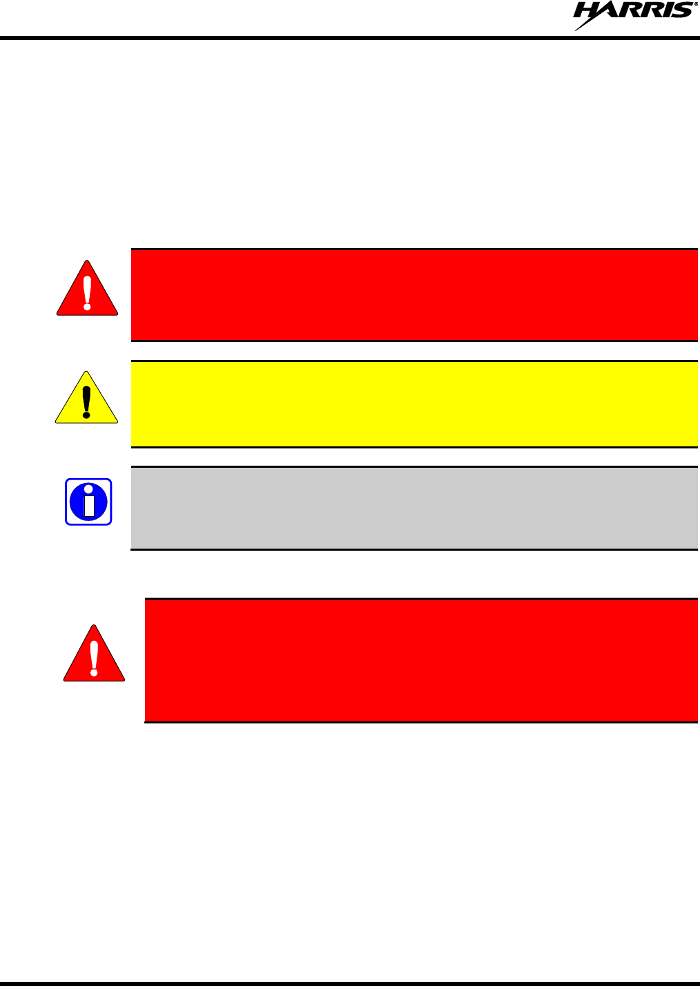
The WARNING symbol calls attention to a procedure, practice, or the like, which, if
not correctly performed or adhered to, could result in personal injury. Do not
proceed beyond a WARNING symbol until the conditions identified are fully
understood or met.
The CAUTION symbol calls attention to an operating procedure, practice, or the like,
which, if not performed correctly or adhered to, could result in damage to the equipment
or severely degrade the equipment performance.
The NOTE symbol calls attention to supplemental information, which may improve
system performance or clarify a process or procedure.
1.2 SAFETY TRAINING INFORMATION
The Harris XG-15P portable radio generates RF electromagnetic energy during
transmit mode. This radio is designed for and classified as “Occupational Use
Only,” meaning it must be used only during the course of employment by
individuals aware of the hazards and the ways to minimize such hazards. This
radio is NOT intended for use by the “General Population” in an uncontrolled
environment.
The XG-15P portable radio has been tested and complies with the FCC RF exposure limits for
“Occupational Use Only.” In addition, this Harris radio complies with the following Standards and
Guidelines with regard to RF energy and electromagnetic energy levels and evaluation of such levels for
exposure to humans:
FCC OET Bulletin 65 Edition 97-01 Supplement C, Evaluating Compliance with FCC Guidelines for
Human Exposure to Radio Frequency Electromagnetic Fields.
American National Standards Institute (C95.1 – 1992), IEEE Standard for Safety Levels with Respect
to Human Exposure to Radio Frequency Electromagnetic Fields, 3 kHz to 300 GHz.
American National Standards Institute (C95.3 – 1992), IEEE Recommended Practice for the
Measurement of Potentially Hazardous Electromagnetic Fields – RF and Microwave.
WARNING
CAUTION
NOTE
WARNING
14221-1450-2000
7
IC Standard RSS-102, Issue 4, 2010: Spectrum Management and Telecommunications Radio
Standards Specification. Radiofrequency Exposure Compliance of Radiocommunication Apparatus
(All Frequency Bands).
DIRECTIVE 2004/40/EC OF THE EUROPEAN PARLIAMENT AND OF THE COUNCIL of 29
April 2004 on the minimum health and safety requirements regarding the exposure of workers to the
risks arising from physical agents (electromagnetic fields) and amended by:
Directive 2007/30/EC of the European Parliament and of the Council of 20 June 2007
Directive 2008/46/EC of the European Parliament and of the Council of 23 April 2008
Regulation (EC) No 1137/2008 of the European Parliament and of the Council of 22 October
2008
Directive 2012/11/EU of the European Parliament and of the Council of 19 April 2012
1.2.1 RF Exposure Guidelines
To ensure that exposure to RF electromagnetic energy is within the FCC allowable
limits for occupational use and/or the exposure limit values in Annex A of EU Directive
2004/40/EC, always adhere to the following guidelines:
DO NOT operate the radio without a proper antenna attached, as this may damage the radio and may
also cause the FCC RF exposure limits and/or the exposure limit values in Annex A of EU Directive
2004/40/EC to be exceeded. A proper antenna is the antenna supplied with this radio by Harris or an
antenna specifically authorized by Harris for use with this radio. (Refer to Table 6-1.)
DO NOT transmit for more than 50% of total radio use time (“50% duty cycle”). Transmitting more
than 50% of the time can cause FCC RF exposure compliance requirements and/or the exposure limit
values in Annex A of EU Directive 2004/40/EC to be exceeded. The radio is transmitting when the
“TX” indicator appears in the display. The radio will transmit by pressing the “PTT” (Push-To-Talk)
button.
ALWAYS transmit using low power when possible. In addition to conserving battery charge, low
power can reduce RF exposure.
ALWAYS use Harris authorized accessories (antennas, batteries, belt clips, speaker/mics, etc). Use of
unauthorized accessories may cause the FCC Occupational/Controlled Exposure RF compliance
requirements and/or the exposure limit values in Annex A of EU Directive 2004/40/EC to be
exceeded. (Refer to Table 1-1.)
As noted in Table 1-1, ALWAYS keep the housing of the transmitter AT LEAST 1.4 cm (0.55
inches) from the body and at least 2.5 cm (0.98 inches) from the face when transmitting to ensure
FCC RF exposure compliance requirements and/or the exposure limit values in Annex A of EU
Directive 2004/40/EC are not exceeded. However, to provide the best sound quality to the recipients
of your transmission, Harris recommends you hold the microphone at least 5 cm (2 inches) from
mouth, and slightly off to one side.
CAUTION

14221-1450-2000
8
Table 1-1: RF Exposure Compliance Testing Distances
RADIO FREQUENCY
(MHz)
TESTED DISTANCES
(worst case scenario)
Body1
Face
700/800 MHz
(768.0125 - 775.9875)
(798.0125 - 804.9875)
(806.0125 - 815.09875)
(851.0125 - 860.9875)
1.4 cm (0.55 in.)
2.5 cm (0.98 in.)
The information in this section provides the information needed to make the user aware of RF exposure,
and what to do to assure that this radio operates within the FCC RF exposure limits and/or the exposure
limit values in Annex A of EU Directive 2004/40/EC.
1.2.2 Electromagnetic Interference/Compatibility
During transmissions, this Harris radio generates RF energy that can possibly cause interference with
other devices or systems. To avoid such interference, turn off the radio in areas where signs are posted to
do so. DO NOT operate the transmitter in areas that are sensitive to electromagnetic radiation such as
hospitals, aircraft, and blasting sites.
1.3 REGULATORY APPROVALS
1.3.1 Part 15
This device complies with Part 15 of the FCC Rules. Operation is subject to the following two conditions:
1. This device may not cause harmful interference, and
2. This device must accept any interference received, including interference that may cause undesired
operation.
1.3.2 Industry Canada
This device complies with Industry Canada license-exempt RSS standard(s). Operation is subject to the
following two conditions: (1) this device may not cause interference, and (2) this device must accept any
interference, including interference that may cause undesired operation of the device.
1.4 OPERATING TIPS
Antenna location and condition are important when operating a portable radio. Operating the radio in low
lying areas or terrain, under power lines or bridges, inside of a vehicle, or in a metal framed building can
severely reduce the range of the unit. Mountains can also reduce the range of the unit.
In areas where transmission or reception is poor, some improvement may be obtained by ensuring that the
antenna is vertical. Moving a few yards in another direction or moving to a higher elevation may also
improve communications. Vehicular operation can be aided with the use of an externally mounted
antenna.
Battery condition is another important factor in the trouble free operation of a portable radio. Always
properly charge the battery.
1 This is worst case based on the thinnest body mount accessory (belt clip).
14221-1450-2000
9
1.5 EFFICIENT RADIO OPERATION
Keep the antenna in a vertical position when receiving or transmitting a message.
Do NOT hold onto the antenna when the radio is powered on!
1.5.1 Antenna Care and Replacement
Do not use the portable radio with a damaged or missing antenna. A minor burn
may result if a damaged antenna comes into contact with the skin. Replace a
damaged antenna immediately. Operating a portable radio with the antenna missing
could cause personal injury, damage the radio, and may violate FCC regulations.
Use only the supplied or approved antenna. Unauthorized antennas, modifications, or
attachments could cause damage to the radio unit and may violate FCC regulations. (Refer
to Table 6-1.)
1.5.2 Electronic Devices
RF energy from portable radios may affect some electronic equipment. Most modern
electronic equipment in cars, hospitals, homes, etc. is shielded from RF energy. However,
in areas in which you are instructed to turn off two-way radio equipment, always observe
the rules. If in doubt, turn it off!
1.5.3 Aircraft
Always turn off a portable radio before boarding any aircraft!
Use it on the ground only with crew permission.
DO NOT use while in-flight!!
1.5.4 Electric Blasting Caps
To prevent accidental detonation of electric blasting caps, DO NOT use two-way
radios within 1000 feet of blasting operations. Always obey the "Turn Off Two-Way
Radios" signs posted where electric blasting caps are being used. (OSHA Standard:
1926.900)
WARNING
WARNING
CAUTION
CAUTION
WARNING
WARNING

14221-1450-2000
10
1.5.5 Potentially Explosive Atmospheres
Areas with potentially explosive atmospheres are often, but not always, clearly
marked. These may be fuelling areas, such as gas stations, fuel or chemical transfer
or storage facilities, and areas where the air contains chemicals or particles, such as
grain, dust, or metal powders.
Sparks in such areas could cause an explosion or fire resulting in bodily injury or
even death.
Turn off two-way radios when in any area with a potentially explosive atmosphere. It
is rare, but not impossible that a radio or its accessories could generate sparks.
WARNING
14221-1450-2000
11
2. RENSEIGNEMENTS SUR LA RÉGLEMENTATION ET
SÉCURITÉ
2.1 CONVENTIONS SUR LES SYMBOLES DE SÉCURITÉ
Les conventions suivantes sont utilisées dans le présent manuel pour avertir l’utilisateur des précautions
générales de sécurité qui doivent être observées pendant toutes les phases d’opération, d’entretien et de
réparation de ce produit. Le non-respect de ces précautions ou d’avertissements précisés ailleurs enfreint
les normes de sécurité de la conception, de la fabrication et de l’utilisation prévue du produit. Harris
n’assume aucune responsabilité pour le non-respect de ces normes par le client.
MISE EN GARDE
Le symbole MISE EN GARDE attire l’attention sur une procédure ou une
pratique qui, si elle n’est pas correctement effectuée ou observée, pourrait
entraîner une blessure personnelle. Ne pas poursuivre au-delà d’un symbole de
MISE EN GARDE avant que les conditions identifiées soient complètement
comprises ou satisfaites.
AVERTISSEMENT
Le symbole AVERTISSEMENT attire l’attention sur une procédure ou une pratique
opérationnelle qui, si elle n’est pas correctement effectuée ou observée, pourrait
entraîner un bris d’équipement ou une importante baisse de rendement de l’équipement.
REMARQUE
Le symbole REMARQUE attire l’attention sur des renseignements supplémentaires qui
peuvent améliorer le rendement du système ou clarifier un processus ou une procédure.
2.2 RENSEIGNEMENTS SUR LA FORMATION SUR LA SÉCURITÉ
MISE EN GARDE
La radio portative Harris XG-15P produit de l’énergie électromagnétique des RF
lorsqu’en mode de transmission. Cette radio est conçue et classée pour une
« Utilisation professionnelle seulement », ce qui signifie qu’elle ne doit être utilisée
que dans le cadre d’un emploi par des individus conscients des risques et des
moyens de limiter ceux-ci. Cette radio N’EST PAS conçue pour une utilisation par
la « Population générale » dans un environnement non contrôlé.
La radio portative XG-15P a été testée et est conforme aux limites d’exposition aux RF de la FCC pour
une « Utilisation professionnelle seulement ». De plus, cette radio Harris est conforme aux normes et
directives suivantes quant à l’énergie des RF et aux niveaux d’énergie électromagnétique, ainsi qu’à
l’évaluation de ces niveaux pour l’exposition aux humains :
Bulletin 65 du OET de la FCC, édition 97-01, supplément C, portant sur l’évaluation de la conformité
aux directives de la FCC quant à l’exposition humaine aux champs électromagnétiques des
radiofréquences.
American National Standards Institute (C95.1 – 1992), norme de l’IEEE sur les niveaux sécuritaires
d’exposition humaine aux champs électromagnétiques des radiofréquences, 3 kHz à 300 GHz.
American National Standards Institute (C95.3 – 1992), pratique recommandée par l’IEEE pour la
mesure des champs électromagnétiques potentiellement dangereux – RF et micro-ondes.
14221-1450-2000
12
IC la norme RSS-102, Numéro 4, 2010: Gestion du spectre et télécommunications normes
radioélectriques. L'exposition aux radiofréquences Conformité des appareils de radiocommunication
(toutes bandes de fréquences).
2.2.1 Directives sur l’exposition aux RF
AVERTISSEMENT
Pour s’assurer que l’exposition à l’énergie électromagnétique des RF se situe dans les
limites acceptables de la FCC pour l’utilisation professionnelle, respectez toujours les
directives suivantes :
N’utilisez PAS la radio sans qu’une antenne appropriée y soit connectée, car ceci peut endommager la
radio et également causer un dépassement des limites d’exposition aux RF de la FCC. Une antenne
appropriée est celle fournie par Harris avec cette radio, ou une antenne spécifiquement autorisée par
Harris pour être utilisée avec cette radio. (Reportez-vous à Table 6-1.)
Ne transmettez PAS pendant plus de 50 % de la durée d’utilisation totale de la radio (« cycle de
service de 50 % »). La transmission pendant plus de 50 % du temps peut causer un dépassement des
exigences de conformité de la FCC en matière d’exposition aux RF. La radio transmet lorsque
l’indicateur « TX » apparaît sur l’affichage. La radio transmet lorsqu’on appuie sur le bouton « PTT »
(bouton de microphone).
Transmettez TOUJOURS en basse puissance lorsque possible. En plus de préserver la charge de la
pile, une faible puissance réduit l’exposition aux RF.
Utilisez TOUJOURS des accessoires autorisés Harris (antennes, piles, pinces de ceinture, haut-
parleurs/micros, etc.). L’utilisation d’accessoires non autorisés peut entraîner un dépassement des
exigences de conformité pour une exposition aux RF professionnelle ou contrôlée de la FCC.
(Reportez-vous à Tableau 2-1.)
Tel qu’indiqué dans Tableau 2-1, conservez TOUJOURS l’appareil et son antenne à AU MOINS
1,4 cm du corps, et à au moins 2,5 cm du visage pendant la transmission, pour vous assurer de ne pas
dépasser les exigences de conformité de la FCC en matière d’exposition aux RF. Cependant, pour
offrir la meilleure qualité sonore aux auditeurs de votre transmission, Harris recommande de tenir le
microphone à au moins 5 cm de votre bouche et légèrement déplacé sur un côté.
Tableau 2-1: Distances de test de conformité des expositions aux RF
RADIOFRÉQUENCES
DISTANCES TESTÉES
(pire des scénarios)
Corps2
Visage
700/800 MHz
(768.0125 - 775.9875)
(798.0125 - 804.9875)
(806.0125 - 815.09875)
(851.0125 - 860.9875)
1,4 cm
2,5 cm
Dans cette section figurent les renseignements nécessaires pour sensibiliser l’utilisateur à l’exposition aux
RF et sur ce qu’il faut faire pour s’assurer que cette radio fonctionne dans les limites d’exposition aux RF
de la FCC.
2 Ce est le pire des cas basée sur le corps plus mince monter accessoire (clip ceinture).

14221-1450-2000
13
2.2.2 Interférence/Compatibilité Électromagnétique
Pendant les transmissions, cette radio Harris produit de l’énergie des RF qui peut causer de l’interférence
avec d’autres appareils ou systèmes. Pour éviter de telles interférences, fermez la radio dans les zones où
il est indiqué de le faire. N’utilisez PAS le transmetteur dans des zones sensibles aux radiations
électromagnétiques, comme les hôpitaux, les avions et les sites de détonation.
2.3 INTERFÉRENCE DES RADIOFRÉQUENCES
2.3.1 Partie 15 de la FCC
Cet appareil est conforme à la Partie 15 de la réglementation de la FCC. Le fonctionnement est soumis
aux deux conditions suivantes :
1. Cet appareil ne doit pas causer une interférence nuisible; et
2. Cet appareil doit accepter toute interférence reçue, y compris une interférence qui peut causer un
fonctionnement non souhaité.
2.3.2 Industrie Canada
Le présent appareil est conforme aux CNR d'Industrie Canada applicables aux appareils radio exempts de
licence. L'exploitation est autorisée aux deux conditions suivantes : (1) l'appareil ne doit pas produire de
brouillage, et (2) l'utilisateur de l'appareil doit accepter tout brouillage radioélectrique subi, même si le
brouillage est susceptible d'en compromettre le fonctionnement.
2.4 CONSEILS D’UTILISATION
L’emplacement et l’état de l’antenne sont importants pour l’utilisation d’une radio portative. L’utilisation
de la radio dans des zones de faible élévation, sous des lignes électriques ou des ponts, à l’intérieur d’un
véhicule ou dans un immeuble à ossature métallique, peut réduire la portée de l’appareil de manière
considérable. Les montagnes peuvent également réduire la portée de l’unité.
Dans les zones où la transmission ou la réception est insatisfaisante, certaines améliorations peuvent être
obtenues en s’assurant que l’antenne est verticale. Se déplacer de quelques mètres dans une autre
direction ou à un emplacement plus élevé peut également améliorer les communications. L’utilisation
d’une antenne fixée à l’extérieur peut faciliter le fonctionnement dans un véhicule.
L’état de la pile est un autre facteur important d’une utilisation sans tracas d’une radio portative. Chargez
toujours correctement la pile.
2.4.1 Utilisation Efficace de la Radio
Gardez l’antenne dans une position verticale pendant la réception ou la transmission d’un message.
MISE EN GARDE
Ne tenez PAS l’antenne lorsque la radio est allumée!
2.4.1.1 Entretien Et Remplacement De L’antenne
14221-1450-2000
14
MISE EN GARDE
N’utilisez pas la radio portative si son antenne est endommagée ou absente. Une
brûlure légère peut se produire au contact d’une antenne endommagée avec la
peau. Remplacez immédiatement une antenne endommagée. L’utilisation d’une
radio portative alors que l’antenne est absente peut causer des blessures,
endommager la radio et pourrait enfreindre la réglementation de la FCC.
AVERTISSEMENT
Utilisez seulement l’antenne fournie ou une antenne approuvée. Des antennes non
autorisées, des modifications ou des ajouts à une antenne peuvent endommager la radio et
enfreindre la réglementation de la FCC. (Reportez-vous à Table 6-1.)
2.4.1.2 Appareils Électroniques
AVERTISSEMENT
L’énergie des RF provenant de radios portatives peut affecter certains appareils
électroniques. La majorité de l’équipement électronique moderne dans les voitures, les
hôpitaux, les maisons, etc. est blindé contre l’énergie des RF. Cependant, dans les zones
où l’on vous demande de fermer l’équipement de radio bidirectionnelle, respectez toujours
les règles. En cas de doute, éteignez-le!
2.4.1.3 Avion
MISE EN GARDE
Éteignez toujours une radio portative avant d’embarquer à bord d’un avion!
Ne l’utilisez au sol qu’avec la permission de l’équipage.
NE l’utilisez PAS durant le vol!
2.4.1.4 Détonateurs Électriques
MISE EN GARDE
Pour prévenir la détonation accidentelle des détonateurs électriques, n’utilisez PAS
de radios bidirectionnelles à moins de 305 m (1 000 pi) des opérations de détonation.
Respectez toujours les indications « Éteindre les radios bidirectionnelles » situées là
où des détonateurs électriques sont utilisés. (Norme OSHA : 1926.900)
2.4.1.5 Atmosphère Potentiellement Explosive

14221-1450-2000
15
MISE EN GARDE
Les zones ayant une atmosphère potentiellement explosive sont souvent, mais pas
toujours, identifiées clairement comme telles. Il peut s’agir de zones d’alimentation
en carburant, comme les postes d’essence, les installations de stockage ou de
transfert de carburant ou de produits chimiques, ainsi que les zones dont l’air
contient des produits chimiques ou des particules, comme des grains, de la poussière
ou des poudres métalliques.
Des étincelles dans de telles zones peuvent provoquer une explosion ou un incendie,
causant ainsi des blessures ou même la mort.
Éteignez les radios bidirectionnelles dans toute zone ayant une atmosphère
potentiellement explosive. Il est rare, mais pas impossible qu’une radio ou ses
accessoires produisent des étincelles.
14221-1450-2000
16
3. CLEANING
Keep the exterior of the radio, battery, antenna, and radio accessories clean.
Periodically clean using the following procedures:
1. To remove dust and dirt, clean using damp clean cloth (warm water and mild detergent soap).
2. Follow by wiping with damp (warm water) clean cloth. Wipe dry with clean cloth.
3. Remove the battery and wipe the battery and radio contacts using a soft dry cloth to remove dirt or
grease. This will ensure efficient power transfer from the battery to the radio.
4. Remove any accessories and clean the accessories Universal Device Connector (UDC) contacts using
a clean dry cloth. When the UDC is not in use, cover the connector with the protective dust cap to
prevent the build-up of dust or water particles.
5. If the radio is used in a harsh environment (such as driving rain, salt fog, etc.), it may be necessary to
periodically dry and clean the battery and radio contacts with a soft dry cloth or soft-bristle non-
metallic brush.
For more rigorous cleaning, use the following procedure:
CAUTION
Do not use chemical cleaners, spray, or petroleum-based products. They may damage
the radio housing. We recommend using Chemtronics® Electro-Wash® PR (ES-1603) or
equivalent.
1. Apply the cleaning solution to a clean damp cloth and clean the radio.
Do not spray cleaning solution directly on radio. To clean the radio in the speaker and
microphone areas, carefully wipe these areas but prevent the cleaning solution from
entering the speaker or microphone openings.
2. Wipe off the radio with clean damp cloth using mild warm soapy water.
3. Follow up by wiping off the radio with clean damp cloth using warm water only.
4. Wipe dry with clean cloth.
NOTE
14221-1450-2000
17
4. BATTERIES
The XG-15P series portable radios use rechargeable, recyclable Lithium-Ion (Li-Ion) batteries. Please
follow the directions below to maximize the useful life of the battery.
WARNING
Do not disassemble or modify Lithium battery packs. Lithium battery packs are
equipped with built-in safety and protection features. Should these features be
disabled or tampered with in any way, the battery pack can leak electrolyte,
overheat, emit smoke, burst, and/or, ignite.
If the battery is ruptured or is leaking electrolyte that results in skin or eye contact
with the electrolyte, immediately flush the affected area with water. If the battery
electrolyte gets in the eyes, flush with water for 15 minutes and consult a physician
immediately.
4.1 BATTERY CARE/MAINTENANCE
For information regarding the proper care of portable radio battery packs or establishing a battery
maintenance program, refer to ECR-7367 which may be ordered by calling toll free 1-800-368-3277
(international: 1-434-455-6403) or via https://premier.pspc.harris.com/infocenter/.
4.2 STORING LI-ION BATTERY PACKS
If a battery pack is expected to be idle for a month or more, it should be properly prepared. Li-Ion battery
packs should not be stored fully charged. Before storing the battery pack, discharge it to 40% capacity. If
the battery is not discharged prior to storage, its overall capacity may be reduced. Although all battery
packs experience some capacity loss during storage, the shelf life for Li-Ion battery packs is about 3
months. However, note that any capacity drop which occurs during storage is permanent and cannot be
reversed. Li-Ion battery packs should be purchased and used immediately. They should not be stock-
piled without a rotating stock plan.
4.3 CHARGING BATTERY PACKS
Battery chargers are available from Harris with nominal charge times. Combinations include single and
multi-position charge units.
Harris chargers are specifically designed for charging nickel-based and Lithium battery packs. The
chargers are chemistry-specific for the battery packs and automatically adjust the charging profiles
accordingly. Refer to the appropriate charger manual for specific operating instructions.
Observe the following guidelines when charging a battery pack:
Avoid high temperature during charging.
Discontinue use if the charger is overheating.
Only charge Harris battery packs using a charger approved for use by Harris.
Do not leave batteries in the charger indefinitely. For best results leave the battery in the charger for
two to six hours after the Green Ready LED comes on. Then place the battery pack into service and
fully discharge (as indicated by the radio low battery warning) before re-charging.
WARNING
14221-1450-2000
18
If any faults are encountered while charging the battery pack, consult the charger’s manual to determine
the cause and possible corrective action.
4.4 CHANGING THE BATTERY PACK
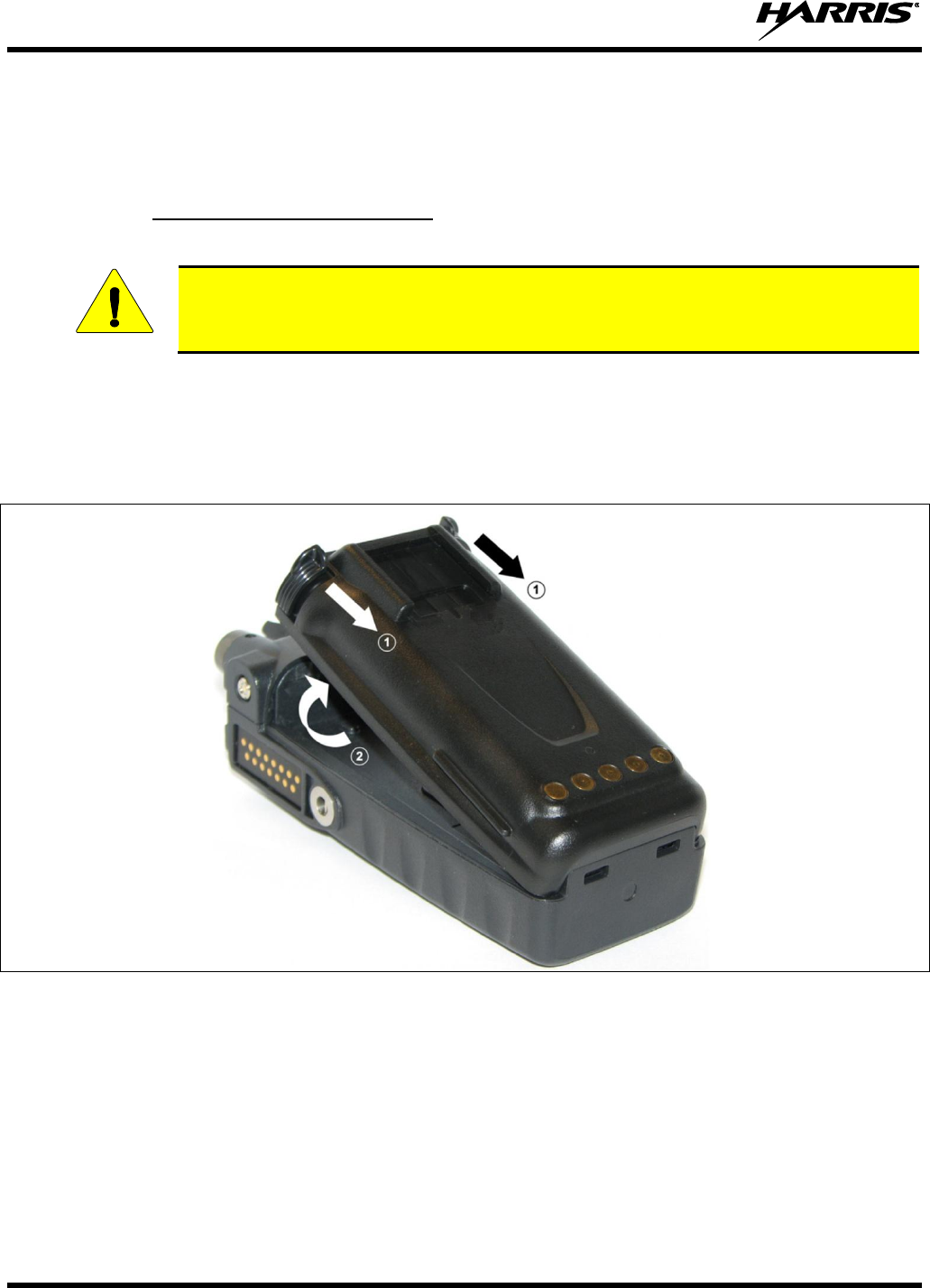
4.4.1 Removing the Battery Pack
Make sure the power to the radio is turned OFF.
Although the XG-15P has been designed to tolerate changing the battery pack without
turning power off, Harris recommends turning the radio off before changing battery packs
to ensure safety and best operation.
1. Press or pull both latches on either side of the battery pack toward the bottom of the radio
simultaneously.
2. Pull the battery away from the radio.
3. Remove the battery pack from the radio.
Figure 4-1: Removing the Battery Pack
CAUTION
14221-1450-2000
19
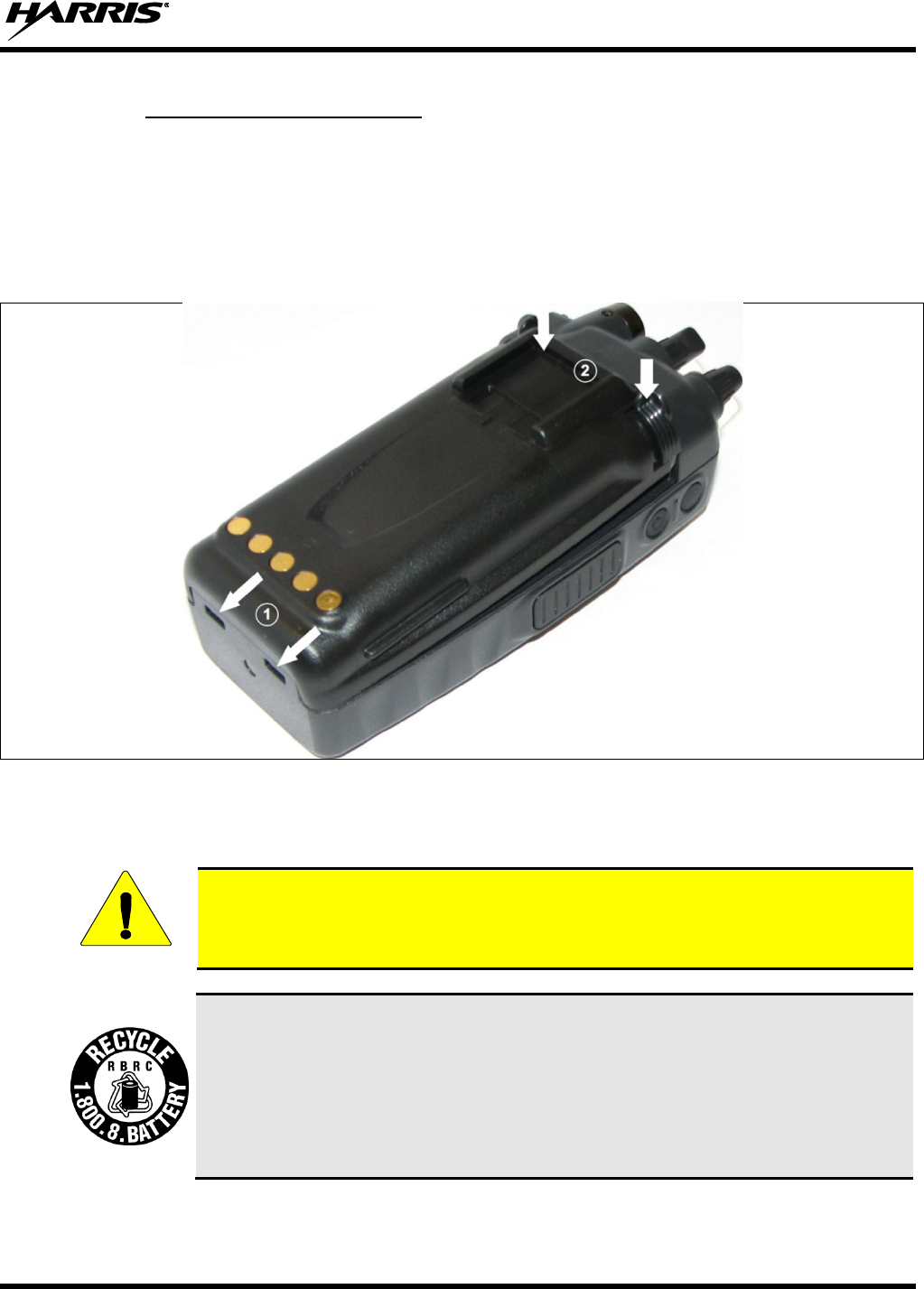
4.4.2 Attaching the Battery Pack
Make sure the power to the radio is turned OFF.
1. Align the tabs at each side on the bottom of the battery pack with the slots at the bottom of the battery
cavity .
2. Push the top of the battery pack down until the latches click to attach the battery to the radio.
3. Tug gently to verify that the latches are secure and the battery pack is properly attached to the radio.
Figure 4-2: Attaching the Battery Pack
4.5 BATTERY DISPOSAL
In no instance should a battery be incinerated. Disposing of a battery by burning will
cause an explosion.
RECHARGEABLE BATTERY PACK DISPOSAL – The product you have
purchased contains a rechargeable battery. The battery is recyclable. At the end of its
useful life, under various state and local laws, it may be illegal to dispose of this
battery into the municipal waste stream. Check with your local solid waste officials for
details in your area for recycling options or proper disposal. Canadian and U.S. users
may call Toll Free 1-800-8-BATTERY® for information and/or procedures for
returning rechargeable batteries in your locality.
CAUTION
14221-1450-2000
20
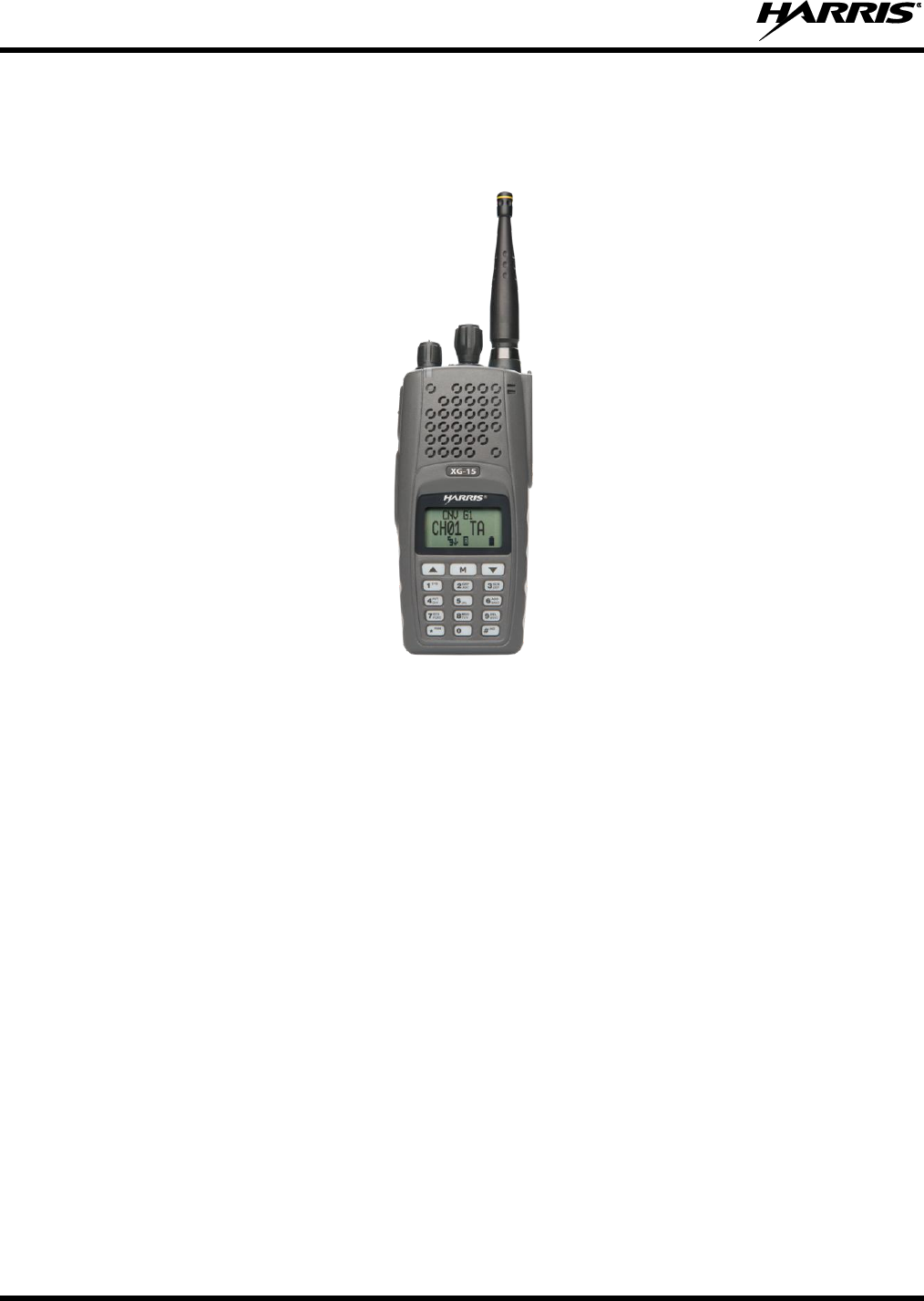
5. INTRODUCTION
The XG-15P series portable radio is available in a System model with a 15-button DTMF front-mounted
keypad.
Figure 5-1: XG-15P Radio
The XG-15P portable radio delivers end-to-end encrypted digital voice and IP data communications. It is
designed to support multiple operating modes including:
P25 Trunked Mode
P25 Digital Conventional Mode
Conventional Analog Mode
The XG-15P supports a full range of advanced digital trunking features, including voice group calls,
priority scanning, emergency calls, late call entry, and dynamic reconfiguration. It performs autonomous
roaming for wide area applications. High quality voice coding and robust audio components assure
speech clarity.
In the trunked modes, the user selects a communications “operating” system and group. While
communicating in a trunked mode, channel selection is transparent to the user and is controlled via digital
communication with the system controller. This provides advanced programmable features and fast
access to communication channels.
In Conventional Analog mode, the user selects a channel and communicates directly on that channel. A
channel is a transmit/receive radio frequency pair.
The exact operation of the radio depends on the operating mode, the radio’s programming, and the
particular radio system. Most features described in this manual can be enabled through programming.
Consult your System Administrator for the particular features programmed into your XG-15P. Then refer
to the corresponding section(s) within this manual for feature and operation information.
14221-1450-2000
21
5.1 WATER RESISTANCE
The XG-15P series portable radios operate reliably even under adverse conditions. These radios meet
MIL-STD-810F specifications for wind driven rain, humidity, and salt fog.
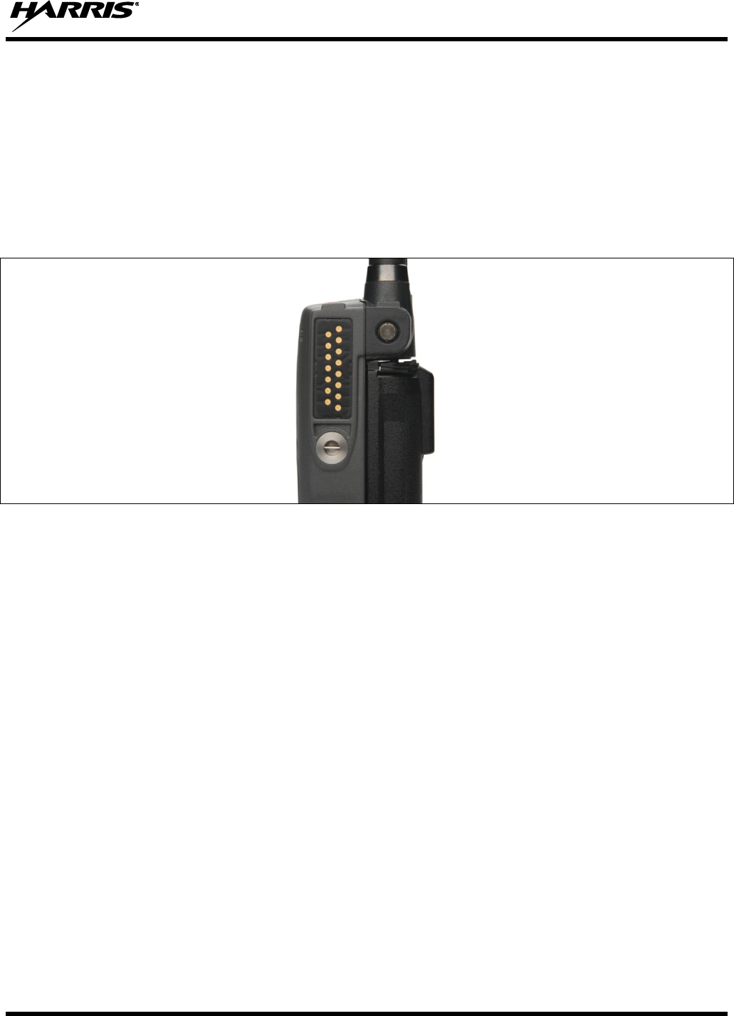
5.2 UNIVERSAL DEVICE CONNECTOR
The Universal Device Connector (UDC) provides connections for external accessories such as a headset,
a speaker-microphone, audio test box, audio test cables, and programming cables. The UDC is located on
the right side of the radio, opposite the PTT Button. The UDC facilitates programming and testing the
radio. The UDC pins perform different functions depending on the accessory attached to the UDC.
Figure 5-2: XG-15P 15-Pin Universal Device Connector
14221-1450-2000
22
6. OPTIONS AND ACCESSORIES
Table 6-1 lists the Options and Accessories tested for use with the XG-15P series portable radios. Refer to
the Products and Services Catalog for a complete list of options and accessories, including those items
that do not adversely affect the RF energy exposure.
Always use Harris authorized accessories (antennas, batteries, belt clips,
speaker/mics, etc). Use of unauthorized accessories may cause the FCC
Occupational/Controlled Exposure RF compliance requirements to be exceeded.
Refer to Table 1-1.
Always use the correct options and accessories (battery, antenna, speaker/mic, etc.) for the
radio. Immersion rated options must be used with an immersion rated radio. Intrinsically
safe options (identified by [FM]) are certified by Factory Mutual and must only be used
with FM certified radios or, if applicable, Canadian Standards Association (CSA) certified
radios. See Table 6-1.
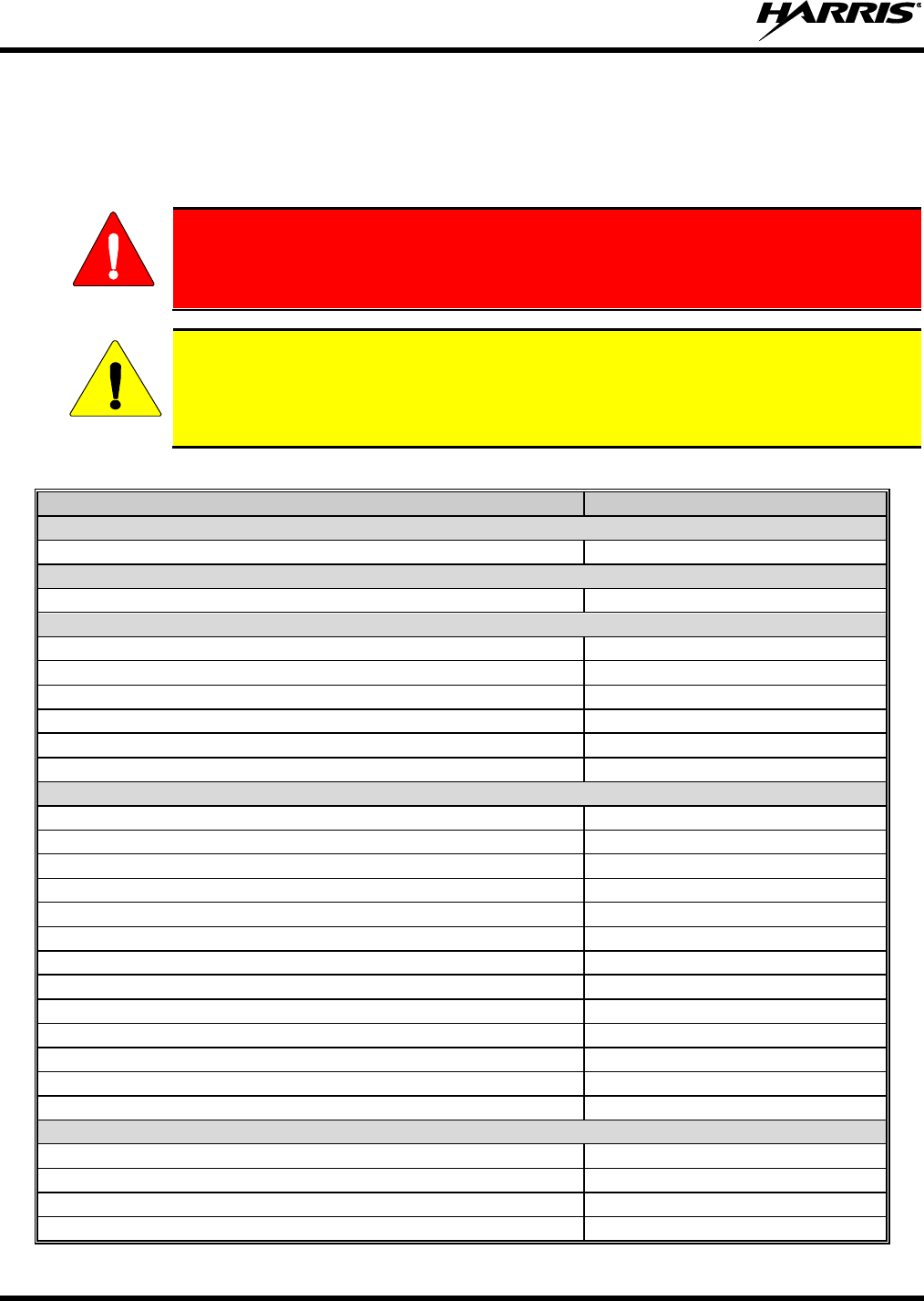
Table 6-1: Options and Accessories
DESCRIPTION
PART NUMBER
ANTENNAS
¼ Wave Whip, Wide Bandwidth, 800 MHz
KRE1011506/2
BATTERIES
Battery, Li-Ion
14002-0214-01
CHARGERS
Power Adapter Kit, VC4000 Charger
PS-007810-001
VC4000 Tri-Chemistry Charger
CH-017231-001
Single Charger, Tri-Chemistry
CH-104560-007
6-bay Charger, Li-Ion/Polymer
12082-0314-01
Wall Mount Kit, 6-Bay Li-Ion/Poly Charger
12082-0315-01
Charger, 6-Bay, Tri-Chemistry
CH-104570-007
AUDIO ACCESSORIES
Speaker Mic without Antenna (cc) provision
MC-023933-001
Speaker-Mic (SML), black, no ant.
MC-023933-003
Speaker-Microphone with Noise-Canceling
MC-023933-501
Rugged Speaker-Microhpone w/ man-down
MC-011617-651
Earphone for Speaker Mic
LS103239V1
Earphone for Speaker Mic, right angle jack
LS103239V2
Ruggedized Speaker Mic, Coil Cord
MC-011617-601
Standard Speaker Mic, Non-Antenna
MC-011617-701
GPS Speaker Mic
MC-009104-002
Speaker Mic, Rugged, Coiled, Hirose Port
MC-011617-611
Tac4 Headset
EA-009580-031
Fire Speaker MIC
12150-4001-03
Fire Speaker MIC
12150-4001-04
DROP SHIP AUDIO ACCESSORIES
Earphone Kit, Black
EA-009580-001
Earphone Kit, Beige
EA-009580-002
2-Wire Kit, Palm Mic, Black
EA-009580-003
2-Wire Kit, Palm Mic, Beige
EA-009580-004
WARNING
CAUTION

14221-1450-2000
23
DESCRIPTION
PART NUMBER
3-Wire Kit, Mini-Lapel Mic, Black
EA-009580-005
3-Wire Kit, Mini-Lapel Mic, Beige
EA-009580-006
Explorer Headset with PTT
EA-009580-007
Lightweight Headset Single Speaker with PTT
EA-009580-008
Breeze Headset with PTT
EA-009580-009
Headset, Heavy Duty, N/C Behind-the-Head, with PTT
EA-009580-010
Ranger Headset with PTT
EA-009580-011
Skull Mic with Body PTT and Earcup
EA-009580-012
Headset, Heavy Duty, N/C Over-the-Head, with PTT
EA-009580-013
Throat Mic with Acoustic Tube and Body PTT
EA-009580-014
Throat Mic with Acoustic Tube, Body PTT, and Ring PTT
EA-009580-015
Breeze Headset with PTT and Pigtail Jack
EA-009580-016
Hurricane Headset with PTT
EA-009580-017
Hurricane Headset with PTT and Pigtail Jack
EA-009580-018
Audio Accessories – Requires UDC to 6-pin Hirose adapter 14002-0197-02
1 Wire Earphone Kit Black (receive only no transmit)
V1-10168
1 Wire Earphone Kit Beige (Receive only no transmit)
V1-10167
2 Wire Palm Microphone Kit Black
V1-10166
2 Wire Palm Microphone Kit Beige
V1-10165
3 Wire Mini Lapel Microphone Kit Black
V1-10164
3 Wire Mini Lapel Microphone Kit Beige
V1-10163
Breeze, lightweight, behind-the-head, single spkr with std PTT
V4-BA2MD1
Breeze, lightweight, behind-the-head, single spkr w/std. PTT &
2.5mm pigtail for PTT
V4-BA2MD3B
Lightweight Single Spkr Padded Headband with std PTT
V4-10190
Ranger Single Speaker gehind-the-head with std PTT
V4-NR2MD1
Over-the-head Dual Speaker Heavy Duty with std PTT
V4-10148
Over-the-Head Dual Speaker Heavy Duty with std PTT-IS/ATEX
V4-10148-S
Behind-the-Head Dual Speaker Heavy Duty with std PTT
V4-10001
Behind-the-Head Dual Speaker Heavy Duty with std PTT-
IS/ATEX
V4-10001-S
Professional Throat Mic with Acoustic Tube & 80mm PTT
V1-T12MD137
Professional Skull Mic with Earcup, Aviation Quality & 80 MM
PTT
V4-10279
CARRYING CASE ACCESSORIES
Leather Carrying Case without D-Rings Kit, consists of:
Leather Case without D-rings
Elastic Strap
Swivel Mount,
used with Belt Loop
Kit: CC-023931-003, incl:
CC-023931-001
FM-011820
KRY 101 1608/2
used with: KRY 101 1609/1
Nylon Case (black) with Belt Loop
CC-023932-001
KRY 101 1609/1
Nylon “T” Strap Holder
KRY 101 1656/1
Nylon Case (Olive Drab)
14002-0217-01
Standard Leather Case with D-Rings
CC-014528-002
Shoulder Strap with Loop for Speaker Mic
CC-014524-001

14221-1450-2000
24
DESCRIPTION
PART NUMBER
Standard Black Nylon Case with Belt Loop Kit, consists of:
Standard Black Nylon Case
Standard Leather Belt Loop
Kit: CC-014534-002, incl:
CC-014534-001
CC-014527
Standard Restraining Strap
used with Shoulder Strap with Loop for Speaker/Mic
CC-014524-002
Leather Case Kit 2: Leather Case w/ D-rings (P/N: CC-023931-
0032), Swivel-Mount (P/N: KRY 101 1608/2), Elastic Strap (P/N:
FM-011820) and Belt Loop (P/N: KRY 101 1609/1)
CC-023931-004
Leather Case w/D-rings, Elastic Strap (P/N: FM-011820),
Shoulder Strap (P/N: CC103333V1)
CC-023931-002
Metal Belt Clip (alternate)
CC-011318
Nylon Case (Orange) w/ Leather Belt Loop (P/N: KRY 101
1609/1)
CC-023932-002
Bee Nylong Case (Black) with Swivel
CC-014534-0014
Bee Nylon Case (Black) with Integral Belt-Clip
CC-014534-002
Bee Leather Case with Swivel
CC-014528-001
Bee Leather Belt Loop
CC-014527
Bee Short Leather Retaining Strap (used with Shoulder Strap)
CC-014524-002
Merzon Belt Loop
14002-0218-01
Leather Belt Loop and Metal Swivel Mount (P/N: KRY 101
1608/2)
KRY 101 1609/1
Metal Belt Clip (standard)
CC23894
MISCELLANEOUS
UDC to 6-pin Hirose adapter
14002-0197-02
14221-1450-2000
25
7. OPERATION
7.1 TURNING ON THE RADIO
1. Power ON the radio by rotating the POWER ON-OFF/VOLUME knob clockwise. A short alert
signal (if enabled through programming) indicates the radio is ready to use.
The radio can be programmed to require the entry of a PIN in order to operate the radio.
Check with your System Administrator if you forget your PIN. As the PIN is entered, an
asterisk is displayed for each digit. The actual value is not displayed.
2. The display shows the last selected system and group or a default system and group (depending on
programming).
3. Adjust the POWER ON-OFF/VOLUME knob to the desired volume level.
4. Select the desired system and group. The display indicates the current system and group names.
5. The radio is now ready to transmit and receive calls.
In the trunked environment, CC SCAN will be displayed if communication with the
system's control channel cannot be established. This may occur if, for example, the radio
is out of range of the trunking site. It may be necessary to move to another location or
select another trunking system to re-establish the control channel link for trunked mode
operations. CC SCAN is displayed on the group line until a control channel is accessed.
The length of time before the radio enters CC Scan after losing communication with the
Control Channel is configurable in RPM.
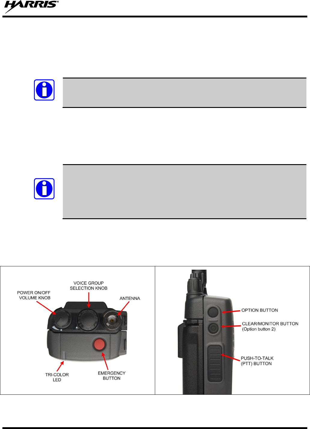
7.2 CONTROLS
The radio features two rotary control knobs and an emergency button mounted on the top of the radio.
The Push-To-Talk and two option buttons are located on the side. The front mounted keypad has 15
buttons.
Figure 7-1: Top View
Figure 7-2: Side View
NOTE
NOTE
14221-1450-2000
26
7.2.1 Buttons, Knobs, and Switch
The functions of the buttons and knob controls vary depending on the mode of operation. Their functions
are detailed in Table 7-1 and Table 7-2.
Table 7-1: Buttons, Knobs, and Switch Functions
POWER ON-
OFF/VOLUME KNOB
Applies power to and adjusts the receiver’s volume. Rotating the control clockwise applies power
to the radio. A single alert tone (if enabled through programming) indicates the radio is
operational.
Rotating the control clockwise increases the volume level. Minimum volume levels may be
programmed into the radio to prevent missed calls due to a low volume setting. While adjusting
the volume the display will momentarily indicate the volume level (i.e., VOL=31). The volume
range is from a minimum programmed level of zero (displayed as OFF in the display) up to 40,
which is the loudest level.
VOICE GROUP
SELECTION CONTROL
KNOB
Selects systems or group/channels (depending on programming). This is a 16-position rotary
knob.
EMERGENCY/ HOME
BUTTON
Automatically selects the pre-programmed Group/System by pressing and holding for a
programmed duration. It can also be used to declare an emergency by pressing and holding for
a programmed duration. The button must be pre-programmed for either operation, but not both.
PTT BUTTON
Push-To-Talk must be pressed before voice transmission begins. In trunked mode, the radio’s ID
is transmitted upon depression of the PTT button.
SIDE OPTION BUTTON
1
Activates one of a number of programmable software options selected during PC programming.
Programmable options include hi/low power settings, keypad lock, LCD contrast, and LCD and
keypad back lighting.
CLEAR/MONITOR
BUTTON
Exits the current operation (removing all displays associated with it) and returns the radio to the
selected Talk Group. Terminates individual and telephone interconnect calls.
In conventional mode: allows the user to monitor the channel for activity.
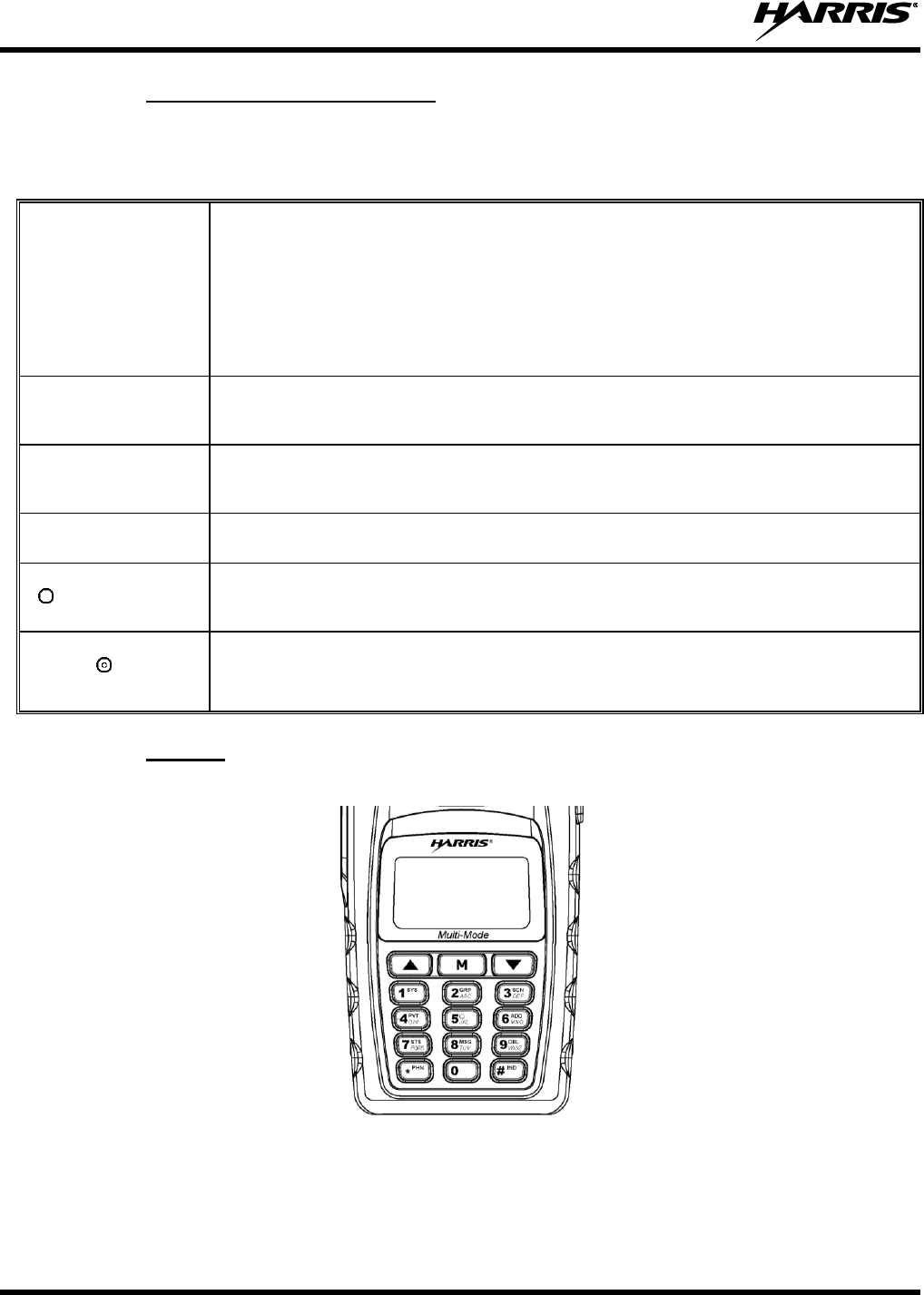
7.2.2 Keypad
The front mounted keypad of the XG-15P has 15 buttons. Refer to Figure 7-3.
Figure 7-3: XG-15P Keypad
14221-1450-2000
27
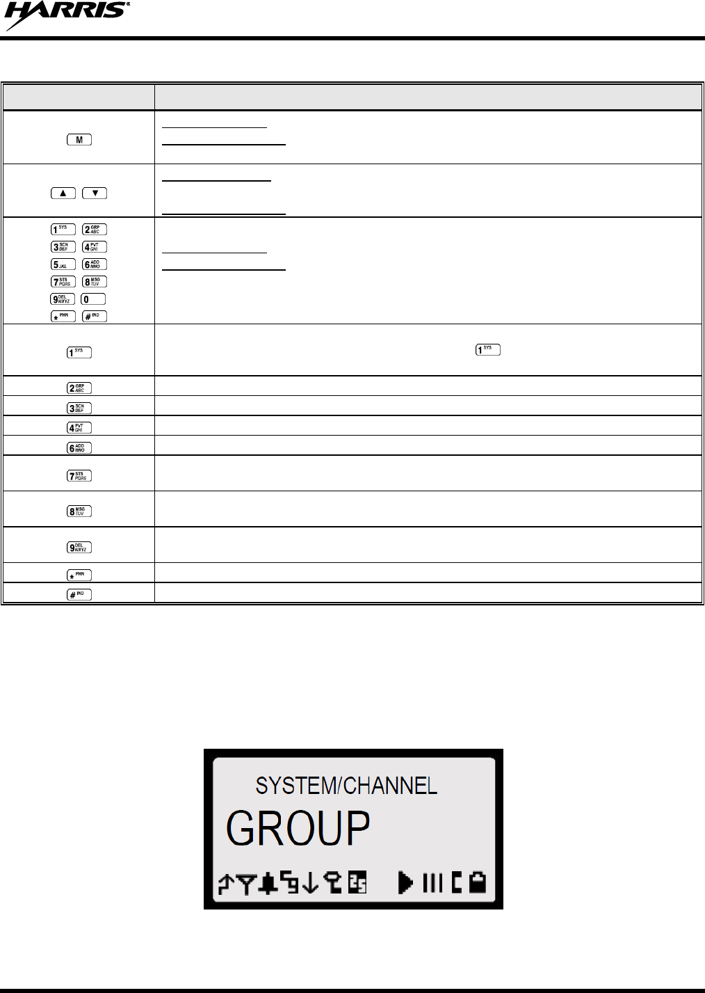
Table 7-2: XG-15P Keypad Functions
KEY
FUNCTION
Primary Function: Accesses the pre-stored menu.
Secondary Function: Activates a selected item within the menu. This is similar to an
“Enter” key.
Primary Function: Allows the user to scroll through available systems, groups, or
channels, depending on personality programming.
Secondary Function: Changes the selection for an item within a list.
Primary Function: Refer to the separate key definitions within this table.
Secondary Function: These keys function much as a typical DTMF telephone pad 0-9,
*, and # keys; and are used to place telephone interconnect and individual (unit-to-
unit) calls.
Selects a specific system. If the rotary knob is used to select the system and more
than 16 systems are programmed in the radio, the key is used to select additional
banks (groupings) of systems.
Selects a specific group.
Turns the Scan operation ON and OFF.
Enables or disables encryption for the system/group/channel displayed.
Adds groups or channels from the currently selected system to the Scan list.
Status. Access to the status list (0-9). The Status key permits the transmission of a
pre-programmed status message to a P25T site.
Message. Access to the message list (0-9). The Message key permits the
transmission of a pre-programmed message to a P25T site.
Deletes selected groups or channels of the currently selected system from the Scan
list.
Initiates telephone interconnect calls.
Initiates individual unit-to-unit calls.
7.3 DISPLAY
The radio display is made up of three lines (see Figure 7-4). Lines 1 and 2 contain eight alphanumeric
character blocks and are used primarily to display system and group names. Line 1 also displays radio
status messages. The 3rd line is used primarily to display radio status icons. All three lines are used to
display menu options when in the menu mode. If programmed, the display backlighting will illuminate
upon power-up or when radio controls are operated.
Figure 7-4: Sample Radio Display
14221-1450-2000
28
7.4 RADIO STATUS ICONS
Status Icons indicate the various operating characteristics of the radio. The icons show operating modes
and conditions and appear on the third line of the display (see Table 7-3).
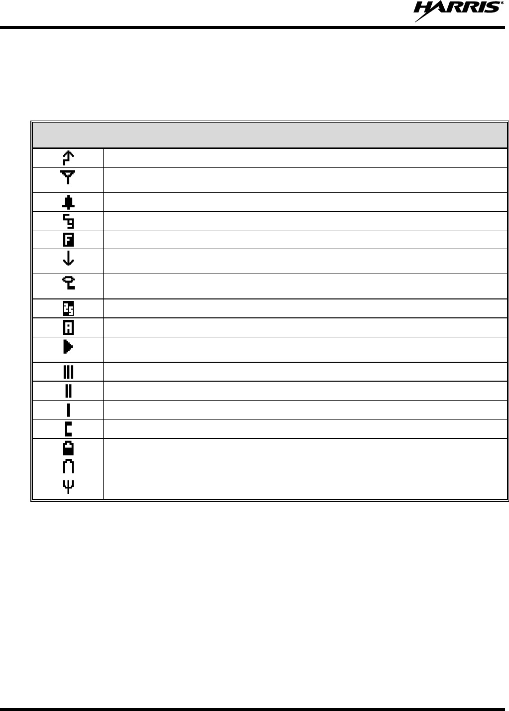
Table 7-3: Status Icon Descriptions
STATUS ICON DESCRIPTIONS
Steady – During all radio transmissions.
Steady – “Busy” transmitting or receiving.
Flashing – Call is queued.
Steady – T99 Mode enabled.
Steady – Channel Guard enabled. If icon is not visible – Channel Guard is disabled.
Steady – Trunked system in Failsoft™ mode.
Steady – Transmit at low power.
If icon is not visible – Transmit at high power.
Steady – Transmit in encrypt mode.
Flashing – Receiving an encrypted call.
Steady – Indicates the current channel is set up as a Project 25 (P25) channel.
Steady – Indicates the current channel is set up as an analog channel.
Animated (rotates clockwise) – Scan mode enabled.
If icon is not visible – Scan is disabled.
Steady – Group or channel in scan list.
Steady – Priority 2 group or channel.
Steady – Priority 1 group or channel.
Steady – Special call mode (individual or telephone).
Steady – Battery charge indicator*.
Flashing – Low battery indicator.
Flashing – Acquiring GPS satellites.
Steady – GPS satellites have been acquired.
*The battery charge indicator illustrates approximate charge only, based on battery voltage.
7.5 TRI-COLOR LED
The Tri-Color LED changes color to indicate radio status and is visible from both the front and top of the
radio (see Figure 7-1). The colors of the LED and the status they represent are defined below.
Green: Receiving
Red: Unencrypted transmission
Orange: Encrypted transmission
14221-1450-2000
29
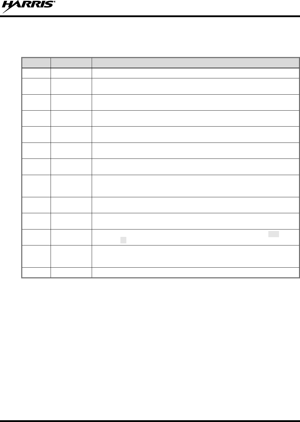
7.6 RADIO STATUS MESSAGES
During radio operation, various radio Status Messages can be displayed. The messages are described
below.
MESSAGE
NAME
DESCRIPTION
QUEUED
Call Queued
Indicates the system has placed the call in a request queue.
SYS BUSY
System Busy
Indicates the system is busy, no channels are currently available, the queue is full, or
an individual call is being attempted to a radio that is currently transmitting.
DENIED
Call Denied
Indicates the radio or talkgroup is not authorized to operate on the selected system
and/or talkgroup.
CC SCAN
Control Channel
Scan
Indicates the control channel is lost and the radio has entered the Control Channel
Scan mode to search for the control channel (usually out of range indication).
WA SCAN
Wide Area Scan
Indicates the radio has entered the Wide Area Scan mode to search for a new
system (if enabled through programming).
SYSC ON
System Scan
Features On
Indicates the System Scan features are enabled.
SYSC OFF
System Scan
Features Off
Indicates the System Scan features are disabled.
LOW BATT
Low Battery
Battery voltage has dropped to the point to where the radio is no longer able to
transmit. The radio will still receive calls until the battery is discharged beyond the
point of operation at which time the radio automatically shuts down.
RXEMER
Receive
Emergency
Indicates an emergency call is being received. This message will be flashing on line
two.
TXEMER
Transmit
Emergency
Indicates an emergency call has been transmitted on this radio. This message will be
flashing on line two.
VOL=31
Volume Level
Indicates the current volume level. The volume level display ranges from OFF
(muted) to 40 (loudest).
WHC
Who Has Called
Indicates an individual call has been received, but not responded to. The indicator
turns OFF if the individual call mode is entered, the system is changed, or the radio is
turned off and then on again.
UNKNOWN
Unknown ID
Indicates an individual call is being received from an unknown ID.
7.7 ERROR MESSAGES
If either of the Error Messages shown below is displayed, the radio is programmed incorrectly or needs
servicing.
DSP ERR
ERR=XXXX
(Power-up only)
or
DIG V
ERR
Where XXXX is the error code and DSP ERR or DIG V ERR is the message.
14221-1450-2000
30
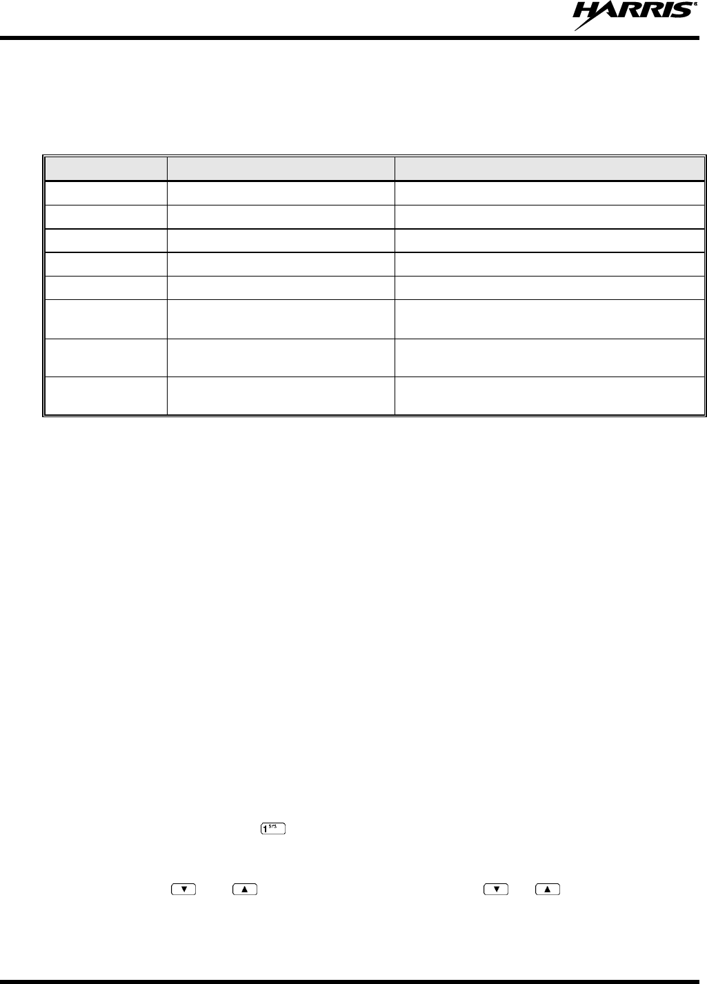
7.8 ALERT TONES
The XG-15P radio provides audible Alert Tones or “beeps” to indicate the various operating conditions
(see Table 7-4).
Table 7-4: Alert Tones
NAME
TONE
DESCRIPTION
Call Originate
one short mid-pitched
OK to talk after pressing the push-to-talk button
Call Queued
one high-pitched
Call queued for processing
Autokey
one mid-pitched
Queued call received channel assignment
System Busy
three low-pitched
System busy or unable to complete call
Call Denied
one low-pitched
Radio is not authorized on the system or group
Carrier Control
Timer
five high-pitched/one long
low-pitched
PTT depressed for maximum length of time
Low Battery
one low-pitched/one short
mid-pitched
Low battery
TX Low Battery
Alert
one low-pitched
After PTT - battery too low to transmit
7.9 VOICE ANNUNCIATION
When enabled via programming, the Voice Annunciation feature provides audible feedback for various
radio operations. The radio can be programmed to play an audio message for any or all of the following.
This message can be a pre-recorded (canned) message or a user-recorded message.
Channel changes
System changes
Encryption On/Off
Noise Cancellation On/Off
Scan On/Off
Talkaround On/Off
For more information on configuring the radio for Voice Annunciation, refer to the Voice Annunciation
Feature manual, 14221-7200-6110.
7.10 SYSTEM/ZONE SELECTION
METHOD 1:
From the control knob: If system/zone selection is programmed to the Voice Group
Selection control knob, select a system/zone by turning the knob to the desired
system/zone number position (1-16). The display registers the new system name on
line one. The button can be programmed to provide access to a “2nd bank” of 16
system number positions (17-32).
METHOD 2:
From the keypad: If system/zone selection is programmed as the primary function of
and , select a system/zone by pressing or to scroll through the
system/zone list. The display registers the new system/zone name on line one.
14221-1450-2000
31
METHOD 3:
Direct Access: Press to enter the system/zone select mode. Press the numeric key
that is mapped to the desired system. Press . The radio will move to the selected
system/zone.
If system selection is programmed to the Voice Group Selection control knob, direct
access to systems/zone will not be available. Pressing or will scroll through
different sets of 16 systems/zones each (banks) if more than 16 systems/zones are
programmed into the radio. The systems within each bank are then selectable via the
Voice Group Selection control knob as described previously in METHOD 1.
Example:
System: 1 = North Group: 1 = Group 1
2 = South 2 = Group 2
3 = East 3 = Group 3
4 = West 4 = Group 4
1. Press . (South is the currently selected system.)
2. Press . (Press 4 to select “West” system.)
3. Press . (West is the newly selected system.)
7.11 GROUP/CHANNEL SELECTION
Several methods can be used to select a new group or channel.
METHOD 1:
From the Control knob: If group selection is programmed to the Voice Group Selection
control knob, select a group by turning the Voice Group Selection control knob to the
desired group number position. The display registers the new group name on line two.
If the knob is moved to a position greater than the number of programmed groups, the
highest programmed group will remain selected. The button can be programmed to
provide access to a “2nd bank” of 16 group number positions (17-32).
METHOD 2:
From keypad: If group selection is programmed as the primary function of and
select a group by pressing or to scroll through the group list. The display
registers the new group name on line two.
METHOD 3:
Direct Access: Press to enter the group select mode. Press the numeric key
mapped to the desired group. Press . The radio will move to the selected group.
In trunked mode, press PTT button and speak normally while holding the microphone approximately two
inches from your mouth.
In conventional mode, press the Monitor/Clear button briefly. If audio is heard or is illuminated, then
the channel is busy. Wait till the channel become available and press the PTT button and speak normally
while holding the microphone approximately two inches from your mouth.
7.12 MODIFY SCAN LIST
1. Press to toggle scan OFF and verify is not displayed.
2. Select group or channel.
3. Press once to remove group or channel from list.
NOTE
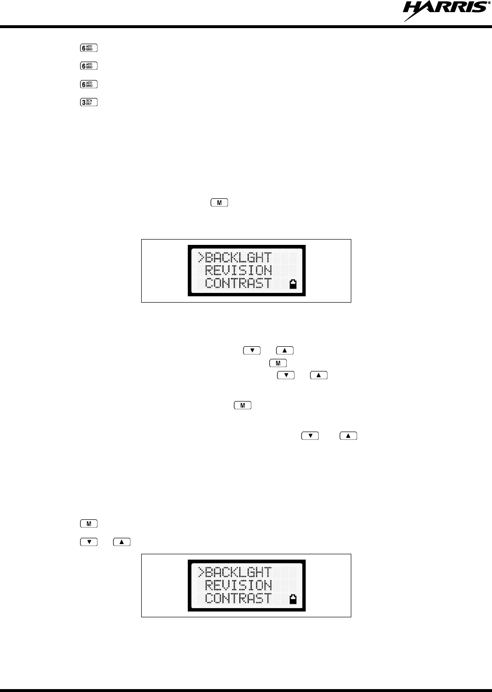
14221-1450-2000
32
4. Press once to add as a normal group or channel.
5. Press twice to add as a Priority 2 group.
6. Press three times to add as a Priority 1 group.
7. Press to re-start scanning.
7.13 MENU
The Menu function accesses features that are not available directly from the keypad. The order and actual
menu items available is configurable through programming. Upon radio power-up, the menu item that is
at the top of the menu list will always be displayed first. Subsequent access to the menu function will
return the last menu item that was shown in the display and cursor position.
1. To enter the menu mode, then press .
2. Upon entering the menu selection mode, Menu options will appear in the display (see Figure 7-5).
Figure 7-5: Menu Display
3. The radio will continue to receive and transmit normally while in the menu function.
4. To scroll through the menu options use the or keys. When the required menu item has been
found align the cursor with the option then press to select it. The menu item's parameter setting
shown in the display can now be changed by using or to scroll through the list of parameter
values.
5. Once the desired setting is reached press to store the value and return the menu option selection
level.
For menu items that display radio information, pressing or will scroll through a list of
informational displays. Possible menu items are listed in Table 7-5.
7.14 MENU ITEM SELECTION PROCESS
An example of the backlight menu item selection process and menu item parameter change is shown in
Figure 7-6.
1. Press . The menu mode is entered.
2. Press or until the display shows:
Figure 7-6: Backlight Menu Item Selection Parameter
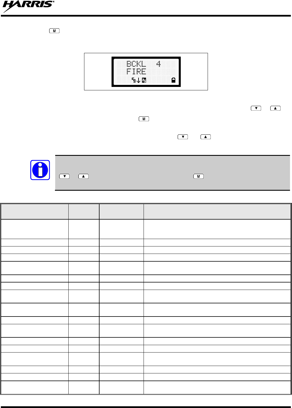
14221-1450-2000
33
3. Press . The backlight menu item is activated. Line one shows the active menu item and its
current parameter setting. Line two shows the currently selected system or group name (see Figure
7-7).
Figure 7-7: Backlight Menu Display
4. The menu item's parameter setting shown in the display can now be changed by using or .
5. Once the desired setting is reached press to store the value and return the menu option selection
level.
For menu items that display radio information pressing or will scroll through a list of
informational displays. An example of information displays is shown in Table 7-5.
The TX POWER menu item, when selected, toggles LOW/HIGH power. It does not use
or to scroll nor is an additional press of the button required.
Table 7-5: Menu Item Information
FEATURE
DISPLAY
PARAMETER
SETTING
COMMENT
Keypad Lock
KEY LOCK
Locked
Unlocked
Locks the keypad. To unlock; press and release “M” then within
1 second press the option button. (This sequence is also a
short cut to locking the keypad.)
Backlight Adjust
BACKLGHT
OFF, 1 through 6
Selects the light level for backlighting.
Contrast Adjust
CONTRAST
1, 2, 3, 4
Selects the display contrast level.
Transmit Power Select
TX POWER
HIGH or LOW
Selects radio output power mode.
Radio Revision Information
REVISION
N/A
Selects the information display to view. Informational display
only. No user selectable settings.
Toggle Scan On/Off
SCAN
ON/OFF
Toggles Scan operation ON/OFF.
Toggle Encryption
PRIVATE
ON/OFF
Toggles Encryption ON/OFF.
Display Current Encryption
Key
DISP KEY
N/A
Displays current encryption key. Informational display only. No
selectable settings.
Home Group/Channel
HOME
Returns the radio to the home system/ channel on conventional
systems and to the home group on trunked systems.
Select Desired System
SYS SEL
N/A
Selects a new system.
Add Group/Channel to Scan
List
SCAN ADD
N/A
Adds to Scan List.
Delete Group/Channel
SCAN DEL
N/A
Deletes Group or Channel from Scan List.
Add/Delete Scan List
SCAN A/D
N/A
Add or Delete from Scan List.
Message
MSG
Permits the transmission of a preprogrammed message to a
P25 site.
ProFile
PROFILE
ON/OFF
Toggles ProFile On/Off.
Talkaround
TALKARND
ON/OFF
Conventional Only. Toggles Talkaround feature ON/OFF.
Select Telephone Numbers
From Phone List
PHONE
N/A
P25 trunked.
NOTE
14221-1450-2000
34
FEATURE
DISPLAY
PARAMETER
SETTING
COMMENT
Data Operation
NO DATA
ON/OFF
P25 trunked. Toggles Data Operation ON/OFF.
Select Individual Call from
IC List
INDV
N/A
P25 modes.
Select Group
GRP
N/A
P25 modes.
Feature Encryption Display
FEATURES
N/A
Indicates current features programmed into the radio as well as
certain information required to add features to the radio.
Informational display only. No user selectable settings.
System Scan Enable
SYS SCAN
ON/OFF
Toggles System Scan feature ON/OFF.
Talk-around
TALK
Toggles Talk-Around ON/OFF.
Type 99 Enable
T99 EN
ON/OFF
Toggles Type 99 Decode ON/OFF.
Display GPS information
GPS
N/A
Displays GPS Status (On/Off), Latitude, Longitude,
Speed/Direction, and time.
Select Mixed System/Zone
ZONE
N/A
Select a Mixed System Zone.
Display Caller ID
CALL ID
N/A
Displays the Radio IDs or alias names for the last 10 received
calls.
Display GPS information
GPS
N/A
Displays GPS Status (On/Off), Latitude, Longitude, Speed/Direction,
and time.
Select Mixed System/Zone
ZONE
N/A
Select a Mixed System Zone.
Display Caller ID
CALL ID
N/A
Displays the Radio IDs or alias names for the last 10 received calls.
View/Modify Custom Scan List
Menu Item:
CUSTSCAN
Allows you to view and edit a Custom Scan list. See Section 7.26.1 for
more information.
7.15 BACKLIGHT ON/OFF
1. Press to access the menu.
2. Press or to scroll through menu until “BCKLGHT” appears.
3. Press to select Backlight menu.
4. Press or to toggle backlight ON and OFF.
5. Press to select new backlight setting.
7.16 CONTRAST ADJUST
1. Press to access the menu.
2. Press or to scroll through menu until “CONTRAST” appears.
3. Press to select Contrast menu.
4. Press or to adjust contrast setting from 1 - 4.
5. Press to select new contrast setting.
14221-1450-2000
35
7.17 DECLARING AN EMERGENCY
1. Press and hold the red Emergency/Home button (the length of time is programmable; check with the
system administrator).
2. *TXEMER* will flash in the display, plus and will be displayed. After 2-3 seconds the
transmit icon will turn off.
3. *TXEMER* and will remain until the emergency is cleared. See Section 7.23 for additional
emergency operation.
4. Press the PTT and will reappear.
5. Release PTT when the transmission is complete.
7.18 LOCKING/UNLOCKING KEYPAD
1. Press button.
2. Within 1 second, press the button on the side of the radio.
7.19 HIGH/LOW POWER ADJUSTMENT
Transmit power adjustment is possible if enabled through programming. Within conventional systems,
transmit power is adjustable on a per channel basis. Within a P25 trunked, transmit power is adjustable on
a per system basis.
There are two ways to toggle between high and low power, described in Sections 7.19.1 and 7.19.2.
7.19.1 Using the Menu Button
1. Press .
2. Using the or keys, scroll until the cursor (>) appears to the left of “TX POWER” in the
display.
3. Press again to toggle between High and Low power.
4. “POWER = HIGH” or “POWER = LOW” will appear momentarily on the top line of the display.
7.19.2 Using the Pre-Programmed Option Button
Press the button. “POWER = HIGH” or “POWER = LOW” will appear momentarily on the top line of
the display.
7.20 ENCRYPTION
The XG-15P portable radio supports DES encryption. When operating on a group or channel programmed
for encryption, all transmissions are private and the radio receives clear and private signals. is
displayed when the encryption is enabled. If the selected group or channel is programmed for auto-select
capability, the mode may be toggled between encrypted and unencrypted by pressing the key, and
then selecting the PRIVATE menu option. Radios programmed for forced encryption do not allow a
change of the transmit mode.
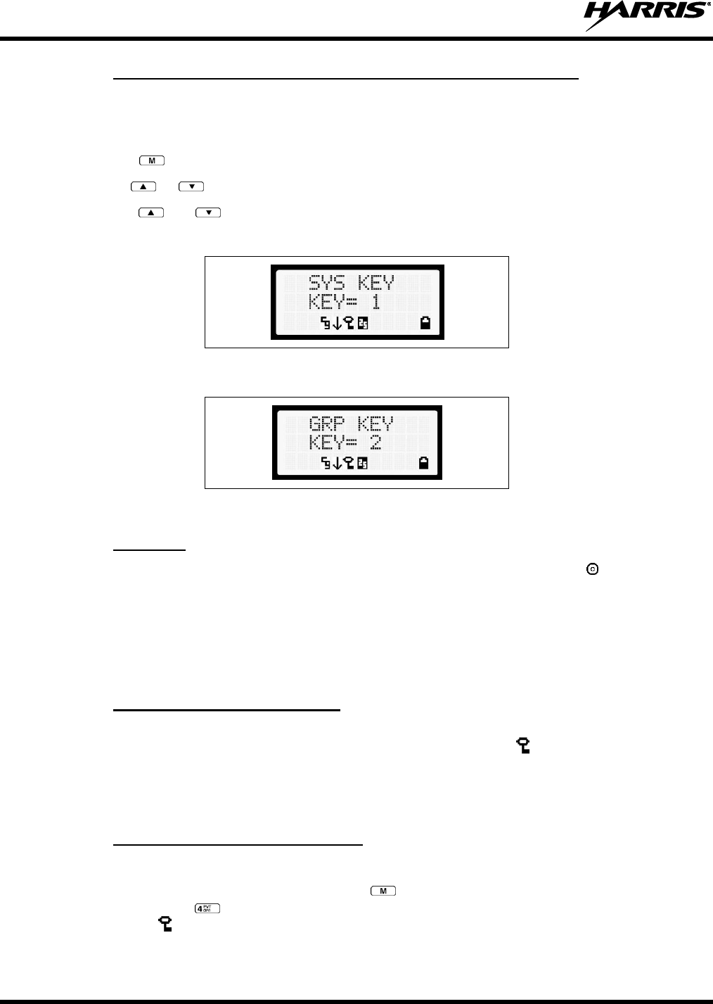
14221-1450-2000
36
7.20.1 Displaying the Currently Used Cryptographic Key Number
To display the Currently Used Cryptographic Key Number for either the system encryption key (for
special call such as individual, phone, all, agency or fleet) or the group/channel key (for group or
conventional calls), perform the following procedure:
1. Press the button.
2. Use the or button to select DISP KEY.
3. Use the or button to toggle between displaying the system key (Figure 7-8) or the
group/channel key (Figure 7-9).
Figure 7-8: System Encryption Key Display
Figure 7-9: Group/Channel Encryption Key Display
7.20.2 Key Zero
All cryptographic keys can be zeroed (erased from radio memory) by pressing the button and while
still pressing this button, press and hold the OPTION button. Press both buttons for 2 seconds. A series
of beeps will begin at the start of the 2 second period and then switch to a solid tone after the keys have
been zeroed. The display will indicate KEY ZERO.
If the cryptographic key(s) are zeroed, one or more keys must be transferred from the Keyloader into the
radio before private communications may continue.
7.20.3 Receiving an Encrypted Call
When receiving, the radio automatically switches between clear or private operation. If the transmission
being received is an encrypted transmission, it will be decrypted, the icon will be displayed, the
receiver will unsquelch, and the message will be heard in the speaker. For this to occur, the selected
group or channel must be programmed for private operation and the correct cryptographic key must be
loaded into the radio.
7.20.4 Transmitting an Encrypted Call
1. Select the desired group or channel.
2. Place the radio in Private Mode by pressing key; then follow the selection mode rules. On a
System radio, the key can be used to toggle the Private Mode ON/OFF. When Private Mode is
enabled, the icon is displayed.

14221-1450-2000
37
3. If the last state of the radio was Private Mode, the Private Mode will be enabled on power-up. Also,
the Private Mode will be enabled if forced operation has been programmed in the radio.
If a group or channel is not programmed for Private Mode operation, PVT DIS will be displayed
if an attempt is made to enable private transmit mode. It is not possible to operate on this
group/channel in Private Mode.
If the radio does not have the correct encryption key loaded, NO KEY# will be displayed and the
call will not be transmitted.
4. Continue with standard transmission procedures. A Private Mode access tone will be heard when the
PTT button is pressed.
7.20.5 Emergencies on Encrypted Group
The radio can be programmed to allow emergency calls to be transmitted in the clear when the radio does
not have the key, or has an invalid key for the encrypted group in emergency.
7.21 SCAN OPERATION
Groups/channels that have been previously added to the scan list on a per system basis may be scanned.
Each system's scan list is retained in memory when the radio is powered OFF or when the battery pack is
removed.
7.21.1 Turning Scan On and Off
1. Toggle Scan operation ON by pressing . icon rotates clockwise to indicate radio is scanning.
2. Toggle Scan operation OFF by again pressing . will disappear.
If the radio scans to a group/channel other than the one selected and then receives a call on the
selected group, the radio switches to the selected group/channel. However, if the “scanned-to”
group/channel is programmed at a higher priority the radio remains on the “scanned-to”
group/channel.
The radio continues scanning if a new group/channel is selected when scan is ON.
3. Pressing the PTT button when scan is ON will cause the radio to transmit on the displayed
group/channel or to the currently selected group (depending on programming).
7.21.2 Add Groups and Channels to a Scan List
1. With scan operation turned OFF, select the desired group/channel to add to the selected scan list.
2. Press . The current priority status of the group/channel will be displayed in column 10 of line
three for a time-out period. If the group is not part of the scan list, the status will be blank.
3. While the status is displayed, press to add the group/channel to the scan list. The icon is
displayed on line three.
4. Press a second time to set the group to Priority 2. The icon is displayed on line three.
5. Press a third time to set the group/channel to Priority 1. The icon is displayed on line three. The
priority level selection sequence only advances the group/channel to next higher priority level and
stops at priority level 1. To select a lower priority level, the group/channel must be deleted from the
scan list and then added back to the scan list. Each new group/channel added to the scan list starts at
the lowest priority. If the Priority 1 and Priority 2 group/channel are already set and a new
14221-1450-2000
38
group/channel is assigned as Priority 1 or Priority 2, the previously assigned group/channel will
change to non-priority scanning. One of the following messages may be momentarily displayed.
SCAN DIS
The radio is not programmed to scan.
FIXED P1
A Priority 1 group/channel has been pre-programmed into the radio. A new Priority 1
group cannot be selected.
FIXD LST
A fixed scan list has been pre-programmed into the radio. It is not possible to change
the list without reprogramming the radio.
To quickly view multiple group scan status, press either or the key. Then
slowly rotate the group knob. Each group/channel status will appear on the display.
7.21.3 Deleting Groups from a Scan List
1. With scan operation turned OFF, select the desired group/channel to delete from the selected scan list.
2. Press . The current status of the group/channel is displayed for a time-out period.
3. While the status is displayed, press to delete the group/channel from the scan list. , ,or
turns OFF. Any group/channel that is not in a scan list will show a "blank" for the time out period
when it is the selected group/channel.
7.21.4 Nuisance Delete
A group/channel can also be deleted from the scan list, if it is not the currently selected group/channel, by
pressing the key during scan operation while the radio is displaying the unwanted group/channel.
The group/channel will be deleted from the scan list in the same manner as if done using the steps above.
Deletions done in this manner will not remain deleted if the radio is powered OFF and then powered ON.
7.22 SYSTEM SCAN (P25 TRUNKED)
The radio can be programmed using Radio Personality Manager (RPM) with the following System Scan
features. These features are automatically enabled when the radio is powered ON. A key or menu option
is also defined to allow the System Scan features to be toggled during radio operation. The System Scan
state will be maintained through system changes but will default to ON when the radio is powered ON.
Enable/Disable via Menu Selection
Press and then use the or buttons to scroll through the selections until SYS SCAN is
displayed. Then press to toggle the System Scan state. The SYSC ON or SYSC OFF display
message is displayed for two seconds to show the new state.
Enable/Disable via Pre-Programmed Keypad Key
Press the key pre-programmed to toggle System Scan and the SYSC ON or SYSC OFF display message
is displayed for two seconds to show the new state.
7.22.1 Wide Area System Scanning
The XG-15P series radio can be pre-programmed through RPM for Wide Area System Scan operation for
roaming across mobile systems. Radio systems manage the radios assigned to the system via a control
channel (CC). Upon the loss of the currently selected system's control channel, radios can be
NOTE

14221-1450-2000
39
programmed to automatically scan the control channels of other systems. If a new control channel is
found, the radio will switch to the new system and sound an alert tone. The amount of time before the
radio enters Control Channel Scan after losing the control channel is configurable in RPM.
7.22.2 Priority System Scan
The radio can also be pre-programmed for Priority System Scan. The priority system is the desired or
preferred system. While receiving the control channel of the selected system, the radio will periodically
leave the selected system and search for the control channel of the priority system. This is done at a pre-
programmed rate defined by the value in the Priority Scan Time control, unless the ProScan™ algorithm is
enabled, as explained in the following sections. This priority scan timer is reset each time the PTT button
is pressed or when the call is received. If the priority system control channel is found, or meets the
predefined criteria (ProScan), the radio will automatically switch to the priority system.
7.22.2.1 Enabling the Wide Area System Scan Function
If the radio cannot find the control channel of the selected system and begins to wide area system scan,
the radio will only scan for the priority system control channel if the priority system is in the wide area
scan list.
7.22.2.2 When ProScan is Enabled
The radio monitors the priority system and will switch to the priority system if the pre-programmed
criteria ProScan options are met. If ProScan is enabled, the rate at which the radio will scan for the
priority system is defined by the System Sample Time control, set in RPM, (refer to RPM On-Line Help).
See Section 7.22.3 for more information on ProScan.
7.22.3 ProScan
The radio may be programmed for ProScan system scan operation for multi-site applications. ProScan is
a multi-site system scanning algorithm. ProScan provides the radio with the ability to select a new
system for the radio to communicate on when the selected system drops below a predefined level. This
algorithm enables each radio to analyze the signal quality of its current control channel and compare it
with the signal quality of the control channel for each site in its adjacent scan list. The signal quality
metric used for the ProScan algorithm is based on a combination of both Received Signal Strength
Indicator (RSSI) and Control Channel Verification (CCV) measurements. When the selected system
degrades to a pre-programmed level, the radio will begin to look for a better control channel. Once a
control channel that exceeds the pre-programmed parameters is found, the radio will change to the new
system and emit a tone (if enabled through programming). If the control channel is completely lost, the
radio will enter Wide Area System scanning and search the programmed adjacent systems until a suitable
control channel is found.
7.23 EMERGENCY OPERATION
The radio's ability to declare an emergency, clear an emergency, remain locked on an emergency system
and group, and the emergency audio and display freeze can each be enabled or disabled through
programming. When an emergency is declared, scanning will stop and restarts only after the emergency
has been cleared.
14221-1450-2000
40
7.23.1 Receiving an Emergency Call
When receiving an Emergency Call on the selected group and system, an alert beep is heard and is
displayed. The message *RXEMER* flashes in the display on line two until the emergency condition is
cleared.
7.23.2 Declaring an Emergency Call
Perform the following steps to send an emergency call to a selected system and group (or on an optionally
pre-programmed group).
1. Press and hold the red EMERGENCY button on top of the radio in front of the antenna for
approximately one second (this time is programmable and therefore could be longer or shorter; check
with the system administrator). The radio will transmit an emergency call request with the radio ID
until an emergency channel assignment is received.
2. When the working channel assignment is received, the radio sounds a single beep indicating the radio
has auto keyed (see Table 7-4) and is ready for voice transmission. *TXEMER* flashes on line two
in the display until the emergency is cleared.
3. Press PTT and speak into the microphone in a normal voice. and momentarily turn ON.
4. Release PTT when the transmission is complete.
To clear the emergency, first press and hold the button. While continuing to hold the button, press
the EMERGENCY button. (This will work if the radio is programmed to clear emergencies.)
7.24 MIXED SYSTEM ZONES
A Zone is a grouping of analog conventional channels, P25 conventional channels, and/or talkgroups.
Mixed System Zones are defined in RPM and can be comprised of any combination of channels/groups
from multiple systems. If a Mixed System Zone is not configured in RPM, it will not appear on the radio.
Up to 50 Mixed System Zones can be defined.
To select a Mixed System Zone:
1. Press .
2. Press or to select ZONE and press .
3. Press or to select the desired Mixed System Zone and press .
Alternately, the System/Group/Channel knob or a button on the radio can be programmed to scroll
through available Mixed System Zones.
When scan is enabled on a system in a Mixed System Zone, the radio continues to display the zone name
or system name per the current radio mode (system/zone). When toggling scan ON/OFF, there is no
change one line 1 of the radio display. If it is showing system name, it continues to show system name; if
it is showing zone name, it continues to show the zone name during scanning.
7.25 CALLER ID
This feature allows you to view the caller ID or alias for up to the last 10 received calls. Received calls
include Group, Announcement, Phone, Patch, SimulSelect, Agency, Fleet, and MDC.
1. Press and press or to select CALL ID. Press . Alternately, a button can be
programmed to access the CALL ID list.

14221-1450-2000
41
2. Press or to scroll through available entries. The most recent call is displayed at the top of the
list. “NO ENTRY” is displayed if there are no entries.
3. Caller ID or “NO ENTRY” is displayed for 10 seconds. Press the Clear button to exit the Caller ID
list.
The most recent call is displayed at the top of the list. The Caller ID list is cleared when power is cycled
on the radio.
7.26 STEALTH MODE
Press the button programmed for Stealth Mode operation to toggle Stealth Mode on or off. During Stealth
Mode, all buttons are disabled except PTT, the button programmed for Stealth operation, Emergency, and
Nuisance delete. The radio will receive and transmit when Stealth Mode is enabled.
The radio can be configured to disable any or all of the following during Stealth Mode:
LCD display
LED
Backlight
Side/alert tones
Stealth Mode can be configured to persist through a power cycle.
7.26.1 Mixed Zone Scan
The Mixed Zone Scan (MZS) feature gives the user the capability to scan based on a custom scan list that
is assigned at the system level. The Custom Scan (CS) list can contain System and Channel/Group
configurations across P25 Trunk, P25 Conventional, and Analog Systems. When a Custom Scan List is
defined on a P25T system, the radio can scan P25T, P25C and Analog systems. When defined on a P25C
or Analog system, the radio only scans conventional channels. MZS also gives the user the capability to
scan beyond the selected system group set.
P25T Scan
When a custom scan list is assigned to a P25T system, the user has the ability to scan P25T, P25C,
and Analog groups/channels. All P25T systems must have the same WACN, System ID, and Unit ID
to be added to the custom scan list.
P25C and Analog Scan
When a custom scan lists is assigned to a P25C or Analog System, the user has the ability to scan
P25C and Analog channels. P25T systems are ignored.
7.26.1.1 Custom Scan List Selection
The Custom Scan List is assigned at the System level. Scanning protocols (Custom Scan, System Scan,
and Conventional Priority Scan) are mutually exclusive. Once a custom scan list is assigned to a system,
when you enable scan, you are scanning the channel/groups defined in the custom scan list. A Custom
Scan List can be assigned to a system through RPM only.
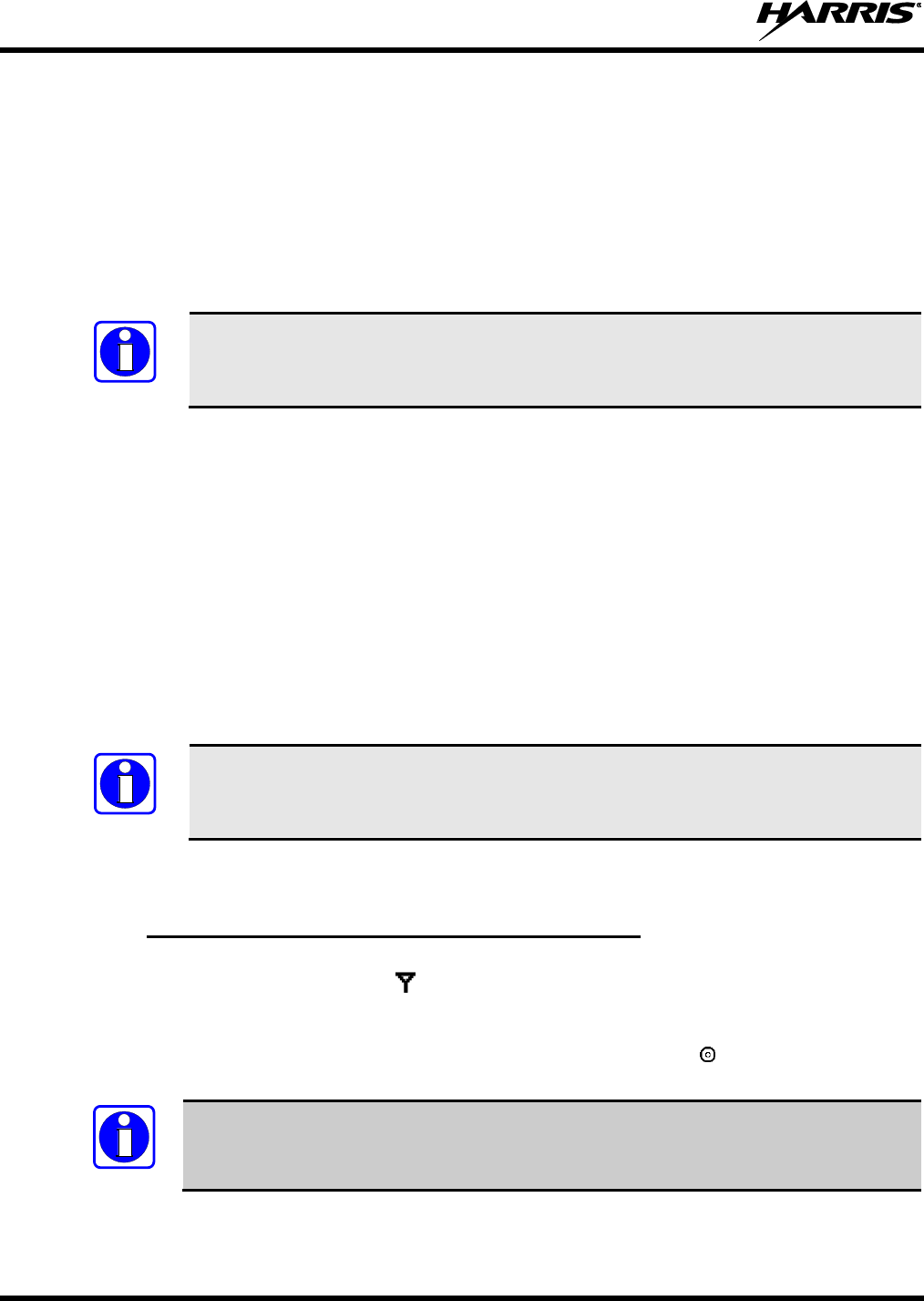
14221-1450-2000
42
7.26.1.2 View Custom Scan Lists
1. From the radio menu, select CUSTSCAN.
2. Select the desired group/channel from the Custom Scan list. Options available for each
channel/group include:
View the channel’s/group’s scan priority.
Delete the channel/group from the scan list.
Nuisance delete the channel/group.
Scan must be off to view a Custom Scan List.
7.26.1.3 Edit Custom Scan Lists
1. From the radio menu, select CUSTSCAN.
2. Select EDIT LST.
3. Select the desired system from the list.
4. Select the desired channel group. Scroll through available options:
Add the channel/group to the scan list.
Change the channel’s/group’s scan priority.
Delete the channel/group from the scan list.
Nuisance delete the channel/group.
Scan must be off to edit a Custom Scan List.
7.27 INDIVIDUAL CALLS (P25 MODES)
7.27.1 Receiving and Responding to an Individual Call
When the radio receives an individual call (a call directed only to the user's radio), it un-mutes on the
assigned working channel and displays . The first line on the display shows the logical ID number of
the unit sending the message, or the associated name if the ID number is found in the individual call list.
The radio can be programmed to ring when an individual call is received. If enabled, the ring begins five
seconds after the caller un-keys and will continue until the PTT button, the button, or the individual
call mode is entered.
The volume of the ring is adjustable through the volume control levels.
NOTE
NOTE
NOTE
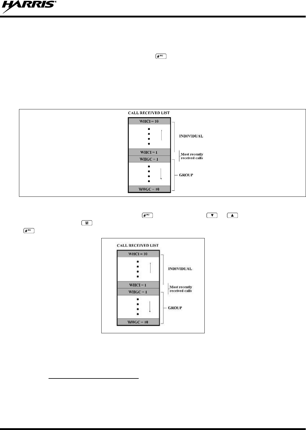
14221-1450-2000
43
If a response is made by pressing the PTT to the call prior to the programmed call-back time-out, the call
will automatically be directed to the originating unit. If a response is not made before the call-back time-
out, the radio will return to normal receive display, and *WHC* will appear on the first line of the LCD.
To respond after the call-back time-out, press the key. The radio's display will show the callers ID on
the first line and WHCI=1 on the second line. Pressing the PTT button at this point will initiate an
individual call back to the original caller.
The radio stores the IDs of the last 10 callers in the Calls Received List as shown. Individual calls are
stored in the top half of the list (1-10) and Group calls are stored in the bottom half of the list (1-10). The
most recent call is stored in position 1, the second most recent call is stored in position 2, etc.
Figure 7-10: Calls Received Lists
To access the Calls Received List, press the key twice. Use the or buttons to scroll through
the list. Pressing the key will display the time elapsed since the call was received. After pressing
the display will appear similar to Figure 7-11.
Figure 7-11: WHC Individual Call Display
Pressing the PTT will initiate an individual call to the displayed logical ID. Powering the radio OFF and
ON will clear this list.
7.27.2 Sending an Individual Call
7.27.2.1 Pre-Stored Individual Calls
The following procedures describe how to initiate and complete a Pre-Stored Individual Call.
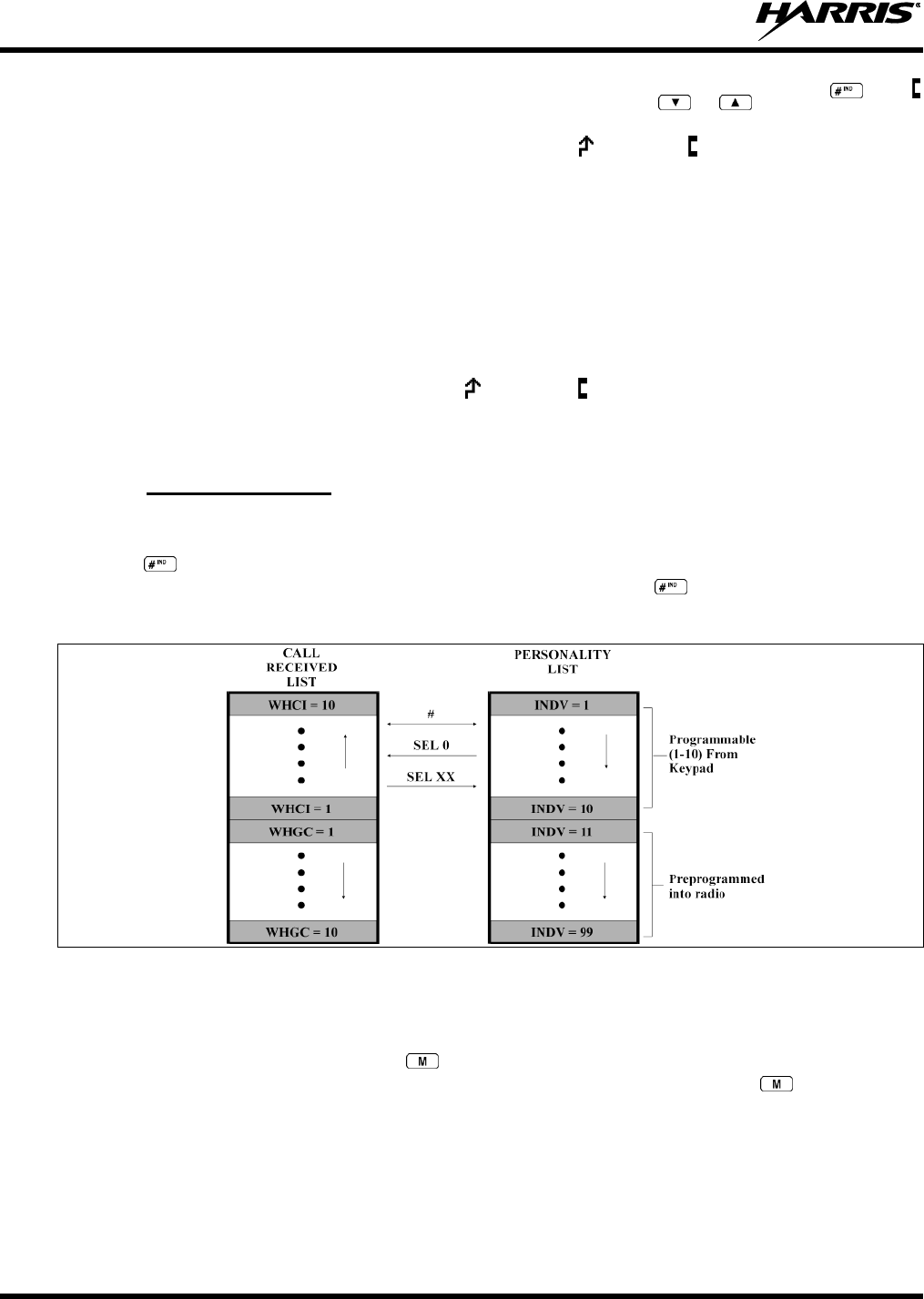
14221-1450-2000
44
1. To select a pre-stored individual phone number, enter the individual call mode using the key.
is displayed. Then scroll through the list of stored numbers using the or keys.
2. Press the PTT button; when the radio is clear to transmit, turns ON, turns OFF and the channel
access tone sounds. Line one shows the called individual's name if found in the list of stored
individuals or LID followed by the logical ID number of the unit being called. The message *INDV*
displays on line two.
7.27.2.2 Direct Dial Individual Calls
The following procedure describes how to initiate and complete a Direct Dial Individual Call:
1. The individual call ID is not stored in the pre-stored list of call IDs but the individual unit ID is
known, it can be entered directly from the keypad.
2. Press and hold the PTT button to transmit. turns ON, turns OFF, and the channel access tone
sounds. Line one shows the called individual's ID followed by the logical ID number of the unit being
called. The message *INDV* displays on line two. Proceed talking into the microphone.
7.27.3 Call Storage Lists
There are two lists available for call storage in the XG-15P series radios, the calls received list (1 - 10)
and the personality list (1 - 99 as defined by the user). When the individual call mode is entered by
pressing , the calls received list is available. The user can toggle to the personality list by selecting
any index other than 0 or toggle between the two lists by pressing the key. If wrap is enabled, the
calls received list wraps on itself and not into the other list.
Figure 7-12: Calls Received and Personality Lists
The saved call list shows all ten storage locations. If no calls have been received, the saved call list will be
empty and the pre-stored list will be available upon entering the individual call mode.
When in the saved call list, pressing the key toggles the time stamp ON and OFF. The time stamp
indicates how long ago the call was received. When in the pre-stored list pressing the key toggles the
Logical IDentification (LID) ON and OFF.
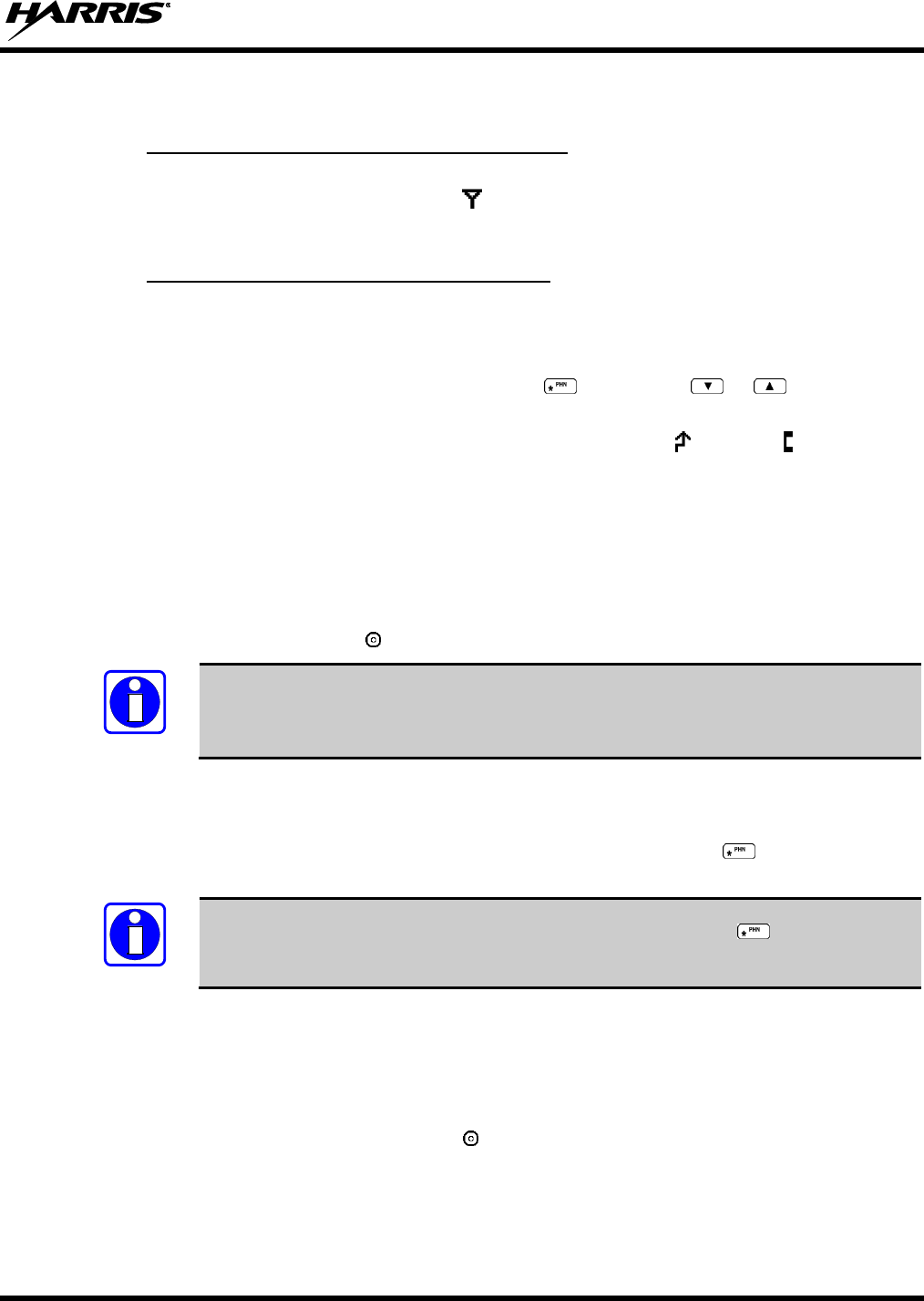
14221-1450-2000
45
7.28 TELEPHONE INTERCONNECT CALLS (P25 TRUNKED)
7.28.1 Receiving a Telephone Interconnect Call
When the radio receives a telephone interconnect call (a call directed only to the user's radio), it un-mutes
on the assigned working channel and displays . The first line displays *PHONE*. The second line
displays *INDV*. Proceed with the call. Press the PTT to talk, release the PTT to listen.
7.28.2 Sending a Telephone Interconnect Call
7.28.2.1 Pre-Stored Number
Use the following procedures to initiate and complete a Telephone Interconnect call:
1. To select a previously stored phone number, press the key. Use the or buttons to scroll
through the list of stored numbers.
2. Press and release the PTT button. When the radio is clear to transmit, turns ON, turns OFF, and
the channel access tone sounds. Line one shows the accompanying name selected from the list of
stored numbers. The message *PHONE* appears on line two of the display. The radio then
automatically transmits the programmed number stored in the special call queue.
3. A telephone ring will be heard from the speaker. When someone answers the phone, press the PTT
button and speak into the microphone. Release the PTT button to listen to the callee. Unsuccessful
interconnect signaling returns the radio to the normal receive mode and the number remains displayed
until the special call is cleared or the time-out expires or another group or system is selected.
Terminate a call by pressing the button.
In half-duplex mode, only one person may talk at a time. The radio PTT button needs
to be pressed in order to communicate to the individual called and released for the
individual called to be heard.
7.28.2.2 Direct Dialing of Phone Calls
1. If the phone number is not stored in the pre-stored list of phone numbers, but the phone number is
known, it can be entered directly from the keypad. Start by pressing the key, then enter the
required number from the keypad. Press and release the PTT button.
The last number directly entered can be recalled by first pressing then pressing the
PTT button.
2. A telephone ring can be heard from the speaker. When someone answers the phone, press and hold
the PTT button and speak into the microphone. Release the PTT button to listen to the individual
called. Unsuccessful interconnect signaling returns the radio to the normal receive mode and the
number remains displayed until the special call is cleared or the time-out expires or another group or
system is selected.
3. To terminate the call, momentarily press the button.
NOTE
NOTE

14221-1450-2000
46
7.28.3 Dual-Tone Multi-Frequency: Overdial
Once the radio has established a connection to the public telephone system, it may be necessary to “over-
dial” more digits to access banking services, answering machines, credit card calls, or other types of
systems that require Dual-Tone Multi-Frequency (DTMF) access digits.
Overdial operation can also be used to initiate a telephone interconnect call via DTMF signaling if a dial
tone has already been accessed on the system. This method makes a telephone interconnect call while
operating in the conventional mode but will also function in trunked mode if a dial tone is directly
accessible.
Telephone numbers and other number sequences for overdialing can be stored in the phone list when
programming the radio. These numbers are accessed by pressing the key, then following the
selection mode rules. Perform the following procedures to access and dial these stored numbers.
1. Follow the procedure in Section 7.28.2 to establish a connection to the telephone system or consult
the system administrator for the procedure to access a dial tone on the trunked or conventional
system.
2. Overdial numbers are transmitted using one of the following methods:
METHOD 1:
1. Enter the overdial selection mode by pressing the button.
2. Use the or buttons to scroll through the list of stored numbers. is
displayed. Press the PTT to send the overdial sequence once. If the number needs to
be transmitted again it must be selected or entered again (this prevents unwanted
numbers from being sent the next time the PTT button is pressed during the call).
Overdial select/entry mode remains active until the call is dropped, cleared, or is
pressed. The overdial select/entry mode can be re-entered if the call is still active by
pressing .
METHOD 2:
1. Enter the overdial selection mode by pressing the button.
2. Press and hold the PTT button while entering the overdial number sequence from the
keypad. This method sends DTMF tones during individual, telephone interconnect,
trunked group, or conventional channel calls. Press the PTT to send the overdial
sequence once. If the number needs to be transmitted again it must be selected or
entered again (this prevents unwanted numbers from being sent the next time the PTT
button is pressed during the call). Anytime the PTT button is pressed and held, the
keypad is enabled for DTMF entry.
Overdial select/entry mode remains active until the call is dropped, cleared, or is
pressed. The overdial select/entry mode can be re-entered if the call is still active by
pressing .
This overdial select/entry mode remains active until dropped, cleared, or is pressed. The overdial
select/entry mode can be re-entered if the call is still active by pressing the button.
7.29 PRE-STORING INDIVIDUAL AND TELEPHONE INTERCONNECT
CALLS FROM THE KEYPAD
Individual Call ID numbers, telephone numbers, and other number sequences for overdialing are stored in
the special calls lists when programming the radio. The first ten entry locations of these lists can be
changed by the radio operator. The keypad is used when adding, changing, and storing numbers in these
entry locations.
Use the following procedure to store a number in one of the first ten entries of a special call list:
14221-1450-2000
47
1. Press the or button to enter the individual call list or the phone call list. is displayed.
2. Scroll through the list using the or keys until one of the first ten entries is reached. NO
ENTRY is displayed if the location is empty.
3. Enter the desired number. If necessary, a pause can be entered by pressing and holding 0-9, , or
until an underscore appears in the display (telephone interconnect only). The individual call list
entries will accept up to 5 digits. The phone call list entries accept a combination of up to 31 digits
and pauses.
4. Press and hold the key until the display changes indicating that the number has been stored.
Repeat steps 1-4 to store additional numbers, to change numbers already stored, or to change the storage
location of a number.
7.30 STATUS/MESSAGE OPERATION (P25 MODES)
The Status and Message operations allow for the transmission of a pre-programmed status or a pre-
programmed message to a P25T site. Each Status and Message is assigned an ID then cross-referenced
with the representative status condition (“Off Duty,” for example) or a message (“Call home”). In
addition, Status conditions can also be associated with a programmable Menu entry (required for second
method of transmitting a Status condition (see Section 7.30.1).
7.30.1 Status Operation
One of two methods can be used to transmit a status condition.
METHOD 1:
1. Press the key, then use the or buttons to scroll to the pre-programmed
status condition. STATUS and 0 through 9 pre-programmed status selections are
available from the menu.
2. If STATUS is selected, you need to enter the number of the status condition you
intend to transmit. If no status has been programmed for the selected number key, the
radio will display NO ENTRY. A valid selection will display the status for a pre-
programmed time.
After the time-out expires or the key has been pressed (the key will override the
time-out period), the status is selected and will be transmitted to the site or stored in the
radio memory where it can be polled by the site at a future time.
METHOD 2:
1. Press the key.
2. Press the corresponding pre-programmed 0 through 9 status condition key. If no
status has been programmed for the selected number key, the radio will display
NO ENTRY. A valid selection will permit the status condition to appear in the top
line of the display and the status ID to appear in the second line of the display for a
pre-programmed time.
After the time-out expires or the key has been pressed (the key will override the
time-out period), the status is selected and will be transmitted to the site or stored in the
radio memory where it can be polled by the site at a future time.
View the currently selected status after it has been transmitted by pressing the key and then the
key and then the button prior to the time-out period. If the status was not sent successfully to the site,
the text associated with the status condition will flash in the display.

14221-1450-2000
48
The status selection can be changed by pressing a different status key 0 through 9, or the status operation
can be cancelled by pressing Clear/Monitor button ( ). Both operations must be carried out prior to the
time-out period.
7.30.2 Message Operation
The following method can be used to transmit a Message using the Message Operation.
1. Press the key.
2. Press the corresponding pre-programmed 0 through 9 pre-programmed “message” key. If no message
has been programmed for the selected number key, the radio will display NO ENTRY. A valid
selection will permit the message to appear in the top line of the display and the message ID to appear
in the second line of the display for a pre-programmed time.
The message selection can be changed by pressing a different message key 0 through 9, or the message
operation can be cancelled by pressing Clear/Monitor button ( ). Both operations must be carried out
prior to the pre-programmed time-out period.
7.31 MACRO KEY OPERATION
Macro key operation permits the user to accomplish a series of keystrokes with a single "macro"
keystroke. Each macro key is capable of executing up to twenty (20) keystrokes, to any push button input
(i.e., keypad keys, OPTION buttons, etc.). Each macro key can be pre-programmed to activate when
pressed or when released.
A macro key may also be pre-programmed to change the key stroke sequence the next time the macro key
is activated.
For detailed operation and assignment of macro keys, contact your communications supervisor or
administrator.
7.32 PORTABLE DATA
The XG-15P series portable radios permit both voice and data calls to be transmitted and received. The
radio can handle only one type of call at a time; however, either data or voice is selected transparently by
the operator through normal usage of the radio.
The radios can be connected to a Mobile Data Terminal (MDT) or to a host computer. Any RS-232
compatible device that supports the Radio Data Interface (RDI) protocol (Version 1.91 or greater) may be
connected to the radio. Support for an MDT or a host computer is a programmable option per radio.
Additionally, radios may also be programmed for data only operation (no voice calls transmitted or
received).
7.32.1 Displays
The following will be displayed during data operation:
DATA T/R
Appears on top line of display when the radio is transmitting/receiving a data call.
DATA OFF
Appears on top line of display when the radio is in the data disabled state.
DATA ON
Appears for two seconds on top line of display when the radio is toggled to the data
enabled state.

14221-1450-2000
49
7.32.2 DATA OFF Operation
The radio can be placed in the data disabled state by any of the following methods. When the data state is
disabled, DATA OFF appears on the top line of the display.
Declaring an emergency (not to be used unless an actual emergency condition exists). Alert tone will
sound.
Pressing Option Button 1 (if pre-programmed as “no data” (ND) key). Alert tone will sound.
Pressing the pre-programmed “no data” (ND) key. Refer to previous bullet.
7.32.3 DATA ON Operation
The data state is enabled by one of the following (depending on how it was disabled). DATA ON will
appear on the top line in the display for two seconds then the display will return to normal.
Pressing the pre-programmed “no data” (ND) key toggles data state ON or OFF.
Clearing an emergency. This is valid only if the emergency caused “DATA OFF” operation.
7.32.4 Exiting Data Calls
Under normal conditions, the radio enters the scan lockout mode and returns to the control channel after
completion of a data call (transmit or receive). If, during a data call, one of the following operations
occurs, the data call is immediately terminated and the radio performs the desired function:
If the PTT is activated.
If an Emergency is declared by pressing the pre-programmed emergency button.
If a group or system is changed.
7.32.5 Scan Lockout Mode
Following the transmission or reception of a data call, if scan is enabled, scanning will stop temporarily.
There are two independent pre-programmed times associated with this mode; one after a received data
call and one after a transmitted data call. During this time the scan indicator will flash to indicate that scan
is enabled but temporarily suspended. This condition typically returns to normal scan operation when the
pre-programmed time expires; however, the following operations and conditions will terminate the scan
lockout mode before the timeout has expired.
Press the button.
Press the PTT.
Change a group or system.
Enter Telephone Interconnect mode.
Enter Individual call mode.
Receive a new emergency assignment.
Declare or clear an emergency.
Receive an individual or phone call.
Receive an Agency, Fleet, or System All Call.
Press to toggle Scan ON or OFF.

14221-1450-2000
50
7.32.6 Data Lockout Mode
During the voice call scan hang time (pre-programmed) the radio will not receive data calls.
7.33 TYPE 99 OPERATION (ANALOG CONVENTIONAL)
Type 99 is a conventional in-band, two-tone sequential signaling method. This conventional signaling
protocol controls the muting and unmuting of a radio. Type 99 encoded base stations, mobiles, or
portables can selectively call individual units or groups of units in a conventional system. Type 99 is
used in paging operations providing a dispatcher with the ability to selectively call a radio or a group of
radios. If Type 99 is enabled in the radio personality, the radio can decode Individual, Group, and
Supergroup Type 99 calls.
In a selective signaling environment, the XG-15P portable radios operate in one of two states, Monitor
mode or Selective Call mode.
In Monitor mode, Type 99 “OFF,” the decoder is disabled and all calls are heard by the user.
In Selective Call mode, Type 99 “ON,” the decoder is enabled and only calls intended for the user
will be heard.
7.33.1 Type 99 with or without Channel Guard
Selective signaling operates with or without Channel Guard. If Channel Guard is enabled, the radio can
be programmed with an "And" or an "Or" option, determined by programming with T99 Mute Control.
If the "And" option is programmed, T99 calls require the correct selective signaling (T99 tone
sequence) AND the correct Channel Guard tones are heard by the user.
If the "Or" option is programmed, calls with the correct Channel Guard tones OR calls with the
correct T99 tone sequence and Channel Guard tones are heard by the user.
A radio operating in Selective Call mode that receives a selective call switches to the Monitor mode (after
decoding the T99 call) and the TX/RX LED flashes green. The TX/RX LED indicates whether the
channel has a carrier signal.
7.33.2 Resetting Type 99 after a Call
After decoding a Type 99 call, the radio operates in Monitor mode and all traffic on the channel is
audible. If the channel has Channel Guard, only the traffic with the radio's Channel Guard tone will be
heard. To reset Type 99 operation, use one of the following methods:
Press the button.
Press the button, if enabled through programming to toggle Type 99 ON/OFF.
Allow the "Auto-Reset" timer, if enabled through programming, to reset the Type 99 decoder.
7.33.3 Type 99 Disable after PTT
The radio may be programmed with the Type 99 Disable after PTT feature, which automatically disables
the Type 99 decoder after a transmission. Use one of the methods outlined in Section 7.33.2 section to
reset Type 99 operation.
7.34 AUDIO PLAYBACK
Every call received by the radio is recorded in internal memory, overwriting the last recorded call. When
the PLAYBACK key is pressed, the last recording is replayed and any future recordings are stopped.
14221-1450-2000
51
Pressing PLAYBACK again repeats the same recorded call. Pressing and holding the PLAYBACK key
until the tone sounds erases the recording and starts the recording of incoming calls again. If a call is
received while the recorded call is playing, the recorded call continues to play, rather than the received
audio. However, if a call is received and the recorded call is played back in close succession received
audio could mute call playback. This feature requires RPM R8A and later, and ECP R15A and later.
The PLAYBACK function must be programmed to a button on the radio via RPM.
7.35 RADIO TEXTLINK OPERATION
Radio TextLink provides a simple means of exchanging pre-defined, or “canned,” text messages. This
section describes how to send messages if the Radio TextLink feature is enabled.
7.35.1 Send TextLink Messages
1. Press to access the menu.
2. Press or to scroll through menu until SND MAIL is displayed. Press to select.
3. Press or to scroll through the pre-defined messages that scroll across the top of the display.
Press to select to select the desired message.
4. Press or to scroll through the list of available destination IDs and select the desired ID with
.
7.35.2 View Received TextLink Messages
Received Messages are listed in the order in which they are received (newest at the top). All messages
include the user LID along with the date and time stored/displayed. The mailbox can hold 16 messages at
a time. If a new Message arrives after the limit is reached, the new message overwrites the oldest
message.
1. Press to access the menu.
2. Press or to scroll through menu until RD MAIL is displayed. Press to select.
3. Scroll through the list of received messages using the or key.
4. Selecting a received message with the key will bring up a reply to sender option.
7.35.3 Delete TextLink Messages
Select DEL MAIL with the key to delete ALL messages in the inbox.
7.35.4 View the Current Time
Select TIME with the key to retrieve the current date and time.
7.36 VIEW GPS INFORMATION
If GPS is enabled in RPM and the GPS Speaker microphone or GPS dongle is connected to the XG-15P,
view your position and satellite information via the GPS Menu. GPS requires an unobstructed view of
the sky and the signal is greatly diminished inside buildings, tunnels, heavily forested areas, etc. GPS may
NOTE

14221-1450-2000
52
not work at all under some conditions, especially in metal enclosures or buildings. flashes on the radio
display when the GPS signal is being acquired; stops flashing after signal is acquired.
1. Press to access the menu.
2. Press or to scroll through menu until GPS is displayed and press to select.
3. Press or to scroll through available information screens.
7.37 CONTROL AND STATUS SERVICES
The XG-15P supports Control and Status services. These services allow the computer application to
monitor and control a radio. The Control and Status Services can be used from a locally-connected
Mobile Data Terminal (MDT) or a network MDT. In some cases, the radio can support both MDTs
simultaneously. However, priority is given to the local MDT.
The Radio Status Service allows an MDT or Fixed End System (FES) to receive real-time status updates
from a radio. An MDT sends Host Attach/Detach messages to the radio as UDP datagrams destined for
the UDP Service Address and Service UDP Port of the radio. All responses and asynchronous reports are
returned to the address and port of the requesting host. Refer to the ECP Control and Status Services
Feature Manual, 14221-7200-6040, for more information on this feature.

14221-1450-2000
53
8. CUSTOMER SERVICE
8.1 CUSTOMER CARE
If any part of the system equipment is damaged on arrival, contact the shipper to conduct an inspection
and prepare a damage report. Save the shipping container and all packing materials until the inspection
and the damage report are completed. In addition, contact the Customer Care center to make
arrangements for replacement equipment. Do not return any part of the shipment until you receive
detailed instructions from a Harris representative.
Contact the Customer Care center at http://www.pspc.harris.com/CustomerService or:
North America:
Phone Number: 1-800-368-3277
Fax Number: 1-321-409-4393
E-mail: PSPC_CustomerFocus@harris.com
International:
Phone Number: 1-434-455-6403
Fax Number: 1-321-409-4394
E-mail: PSPC_InternationalCustomerFocus@harris.com
8.2 TECHNICAL ASSISTANCE
The Technical Assistance Center's (TAC) resources are available to help with overall system operation,
maintenance, upgrades and product support. TAC is the point of contact when answers are needed to
technical questions.
Product specialists, with detailed knowledge of product operation, maintenance and repair provide
technical support via a toll-free (in North America) telephone number. Support is also available through
mail, fax and e-mail.
For more information about technical assistance services, contact your sales representative, or call the
Technical Assistance Center at:
North America: 1-800-528-7711
International: 1-434-385-2400
Fax: 1-434-455-6712
E-mail: PSPC_tac@harris.com
14221-1450-2000
54
9. BASIC TROUBLESHOOTING
Use the contents of Table 9-1 as a troubleshooting guide if the radio is not functioning properly. If
additional assistance is required, contact a qualified service technician or call TAC support at
1-800-528-7711.
Table 9-1: Troubleshooting
SYMPTOM
POSSIBLE CAUSE
POSSIBLE SOLUTION
Radio will not turn on.
Low battery charge.
Change the battery pack to a fully charged pack.
No Audio.
Speaker volume is muted.
Increase the volume level.
Poor Audio.
User is in a poor coverage
area or not on the network.
Move to a better coverage area.
Radio powers off for
no apparent reason.
Radio may be experiencing
very low voltage.
Have the battery checked by an authorized technician.
Radio will not
transmit.
Radio may be out of
coverage area or may be
overheated.
Return to coverage area if possible. If overheated, let
radio cool before retrying transmission. Report this failure
to an authorized technician.
10. WARRANTY
Please register this product within 10 days of purchase. Registration validates the warranty coverage, and
enables Harris to contact you in case of any safety notifications issued for this product.
Registration can be made on-line at the Customer Care center webpage:
http://www.pspc.harris.com/Service/Customerservice.aspx.
While on the webpage, please review the applicable battery and/or product warranty literature.

14221-1450-2000
55
APPENDIX A - CONFIGURING ENCRYPTION
A.1 ENCYRPTION KEYS
Refer to the following documentation for advanced programming and setup instructions:
Harris OTAR Overview Manual - MM-008069-001
Network Key Manager Installation and Configuration Manual - MM-008070-001
Harris UAS Key Management Application Manual - MM-008068-001
Harris Key Manager Key Admin Overview and Operation Manual - MM1000019423
Harris Key Manager Key Loader Overview and Operation Manual - MM1000019424
Motorola® Key Variable Loader (KVL) Device User's Guide
A.1.1 Create Keys Using Harris Key Admin
Harris Key Admin is part of the Harris Key Manager and is used by the Crypto Officer (CO). The CO
creates a Master Set of keys from which a Distribution Set is produced. Using the Key Admin software,
the CO can save keys into Distribution key files for technicians to use in radios.
1. Select Start Programs Harris Key Manager Harris Key Admin.
2. Select New Master Set, Open, or Import from Security Device. Refer to the Key Admin online
help for more information on creating keys.
3. When finished, create a Distribution Key File. A Distribution Key File is used with the Key Loader to
load key sets into the radio and cannot be edited. Refer to the Key Admin online help for more
information on creating the Distribution Key File.
A.1.2 Load Encryption Keys
A.1.2.1 Load UKEKS with Key Loader and RPM (for OTAR-Enabled Systems)
UKEKs are loaded into Harris OTAR radios using the Key Loader application. Key Loader is a part of
Key Manager.
To load encryption keys:
1. Obtain the UKEK file and Storage Location Number (SLN) Binding Report information from the
Crypto Officer (CO).
2. If not already on, power-up the PC that has RPM and the Key Loader applications installed on it, and
start Windows®.
3. Connect the radio to the PC using a serial cable (CA-023407-003).
4. Enter into the Harris Keyload Mode (HKL).
a. Press the radio’s button.
b. Scroll through the menu to select the KEYLOAD option and press the button to
activate.
c. Scroll through and select the HKL option and press the button. The radio can now accept
keys from the Harris Keyloader.

14221-1450-2000
56
5. Load the UKEK file from the Crypto Officer onto the PC.
6. Run the RPM application and setup the radio’s personality according the SLN Binding Report
information.
7. Setup the talk groups and the SLN mappings (Talk Group ID to SLN). This includes mapping SLNs
to the “System” keys (PSTN, All Call, etc.).
8. Select Options P25 OTAR Options and set the following:
a. The OTAR Message Number Period (MNP) as defined by the System Administrator.
b. The radio’s Individual RSI (from the SLN Bindings Report).
c. The KMF’s RSI (from the SLN Bindings Report).
9. Program the personality to the radio.
10. Run the Key Loader application.
11. Open the UKEK file loaded in step 5.
12. Select the Target Device type and click the Load button.
13. The Key Loader reads the target device’s identifying information, retrieves a UKEK of the proper
algorithm type from the UKEK file, and downloads the UKEK to the target device at the proper SLN
and keyset with the proper key ID.
14. Click the Finish button to exit the Key Loader application. New UKEKs have are loaded and the
radio is now ready to accept TEKs via OTAR with the trunked radio network.
A.1.2.2 Load Keys Using Harris Key Loader
Harris Key Loader is part of Harris Key Manager and can be used by the Crypto Officer or Technician to
load the keys into the radio.
Refer to the Harris Key Loader online help if additional information is required when performing this
procedure.
1. Connect the radio to the PC using a serial cable.
2. Power on the radio, if not already.
3. Select Start Programs Harris Key Manager Harris Key Loader.
4. At the Key Loader Welcome screen, click Next.
5. Select Load a Distribution Set into one or more devices.
6. Click Next.
7. Browse to the Key File and enter the password.
8. Click Next to validate the password and continue. If the password is incorrect, the screen will display
an error message.
9. Select communication port from the drop-down and click Next.
10. Select the serial port that you have connected to the radio.
11. Enter into Harris Keyload Mode (HKL).
a. Press the radio’s MENU button.
b. Scroll through the menu to select the KEYLOAD option and press the button to activate.
14221-1450-2000
57
c. Scroll through and select the HKL option and press the button. The radio can now accept
keys from the Harris Keyloader.
12. Select Radio from the drop-down and click Load.
13. Click Finish.
A.1.2.3 Power on the Motorola KVL Device
1. Connect KVL Device to the radio using cable 14002-0143-01.
Once the KVL Device is connected, a keyset is established whether the keys are
loaded or not. You will need to zeroize to bring the radio to a fully zeroized state.
2. Press the radio’s button.
3. Scroll through the menu to select the KEYLOAD option and press the button to activate.
4. Scroll through and select the KVL option and press the button. The radio can now accept keys
from the KVL Device.
A.1.2.4 Load Keys Using Motorola KVL Device
Type 3 Digital Encryption Standard Output Feedback (DES-OFB) is supported. The Type 3 Encryption
keys are loaded via a Motorola Device using Telecommunications Industry Association (TIA)/Project 25
(P25) key fill device protocol. Make sure that valid keys have been created and stored in the KVL Device
before proceeding.
A.1.3 Protected Keys
The Protected Keys feature transfers P25 Voice Keys, from Harris Key Loader to the radio, that have
been encrypted with Key Protection Keys (KPKs). KPKs are nothing more than unprotected Key
Encryption Keys (KEKs). The KPKs need to be loaded into the radio before the Protected Keys are
loaded. Once loaded into the radio, the KPKs will be used to decrypt the Protected Keys.
The radio must be placed into the key loading mode (see Section A.1.2.2) in order to accept the KPKs and
P25 Voice Keys.
NOTE

Public Safety and Professional Communications | www.pspc.harris.com
221 Jefferson Ridge Parkway | Lynchburg, VA USA 24501 | 1-800-528-7711
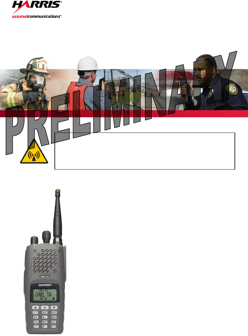
Product Safety Manual
14221-1450-2010
Mar/15
This booklet contains important safety information regarding
Specific Absorption Rate (SAR) and RF exposure limits included
in United States and international standards. Read the
information in this booklet before operating your radio.
XG-15P Portable Radios

2 14221-1450-2010
REV
DATE
DESCRIPTION
-
Mar/15
Initial release.
ACKNOWLEDGEMENTS
The software contained in this device is copyrighted by Harris Corporation. Unpublished rights
are reserved under the copyright laws of the United States.
This device is made under license under one or more of the following US patents: 4,590,473;
4,636,791; 5,148,482; 5,185,796; 5,271,017; 5,377,229; 4,716,407; 4,972,460; 5,502,767;
5,146,497; 5,164,986; 5,185,795; 5,226,084; 5,247,579; 5,491,772; 5,517,511; 5,630,011;
5,649,050; 5,701,390; 5,715,365; 5,754,974; 5,826,222; 5,870,405; 6,161,089; and 6,199,037 B1.
DVSI claims certain rights, including patent rights under aforementioned U.S. patents, and under
other U.S. and foreign patents and patents pending. Any use of this software or technology
requires a separate written license from DVSI.
CREDITS
Harris, EDACS, OpenSky, and assuredcommunications are registered trademarks and ProVoice is
a trademark of Harris Corporation.
RBRC and 1-800-8-BATTERY are registered trademarks of Rechargeable Battery Recycling
Corporation.
AMBE is a registered trademark and IMBE, AMBE+, and AMBE+2 are trademarks of Digital
Voice Systems, Inc.
All other product and brand names are trademarks, registered trademarks, or service marks of
their respective holders. NOTICE
The material contained herein is subject to U.S. export approval. No export or re-export is
permitted without written approval from the U.S. Government. Rated: EAR99; in accordance with
U.S. Dept. of Commerce regulations 15CFR774, Export Administration Regulations.
Information and descriptions contained herein are the property of Harris Corporation. Such
information and descriptions may not be copied or reproduced by any means, or disseminated or
distributed without the express prior written permission of Harris Corporation, PSPC Division,
221 Jefferson Ridge Parkway, Lynchburg, VA 24501.
This product conforms to the European Union WEEE Directive 2012/19/EU. Do not
dispose of this product in a public landfill. This product should be taken to a recycling
center at the end of its life.
The voice coding technology embodied in this product is protected by intellectual property rights
including patent rights, copyrights, and trade secrets of Digital Voice Systems, Inc. The user of
this technology is explicitly prohibited from attempting to decompile, reverse engineer, or
disassemble the Object Code, or in any other way convert the Object Code into human-readable
form.
Repairs to this equipment should be made only by an authorized service technician or facility
designated by the supplier. Any repairs, alterations, or substitution of recommended parts made
by the user to this equipment not approved by the manufacturer could void the user’s authority to
operate the equipment in addition to the manufacturer’s warranty.
This manual is published by Harris Corporation, without any warranty. Improvements and changes to this
manual necessitated by typographical errors, inaccuracies of current information, or improvements to programs
and/or equipment, may be made by Harris Corporation, at any time and without notice. Such changes will be
incorporated into new editions of this manual. No part of this manual may be reproduced or transmitted in any
form or by any means, electronic or mechanical, including photocopying and recording, for any purpose,
without the express written permission of Harris Corporation.
Copyright © 2015 Harris Corporation.

14221-1450-2010 3
TABLE OF CONTENTS Page
1. REGULATORY AND SAFETY INFORMATION ........................................ 4
1.1 SAFETY SYMBOL CONVENTIONS ...................................................... 4
1.2 SAFETY TRAINING INFORMATION .................................................... 5
1.3 OPERATING TIPS .................................................................................... 7
2. RENSEIGNEMENTS SUR LA RÉGLEMENTATION ET SÉCURITÉ ... 10
2.1 CONVENTIONS SUR LES SYMBOLES DE SÉCURITÉ..................... 10
2.2 RENSEIGNEMENTS SUR LA FORMATION SUR LA SÉCURITÉ .... 11
2.3 INTERFÉRENCE DES RADIOFRÉQUENCES ..................................... 13
2.4 CONSEILS D’UTILISATION ................................................................. 13
3. OPTIONS AND ACCESSORIES ................................................................... 15
4. BATTERY PACKS ......................................................................................... 16
4.1 CONDITIONING NIMH BATTERY PACKS ........................................ 16
4.2 CONDITIONING LI-ION OR LI-POLY PACKS ................................... 17
4.3 STORING LI-ION BATTERY PACKS .................................................. 17
4.4 ADDITIONAL INFORMATION ............................................................ 17
4.5 BATTERY DISPOSAL ........................................................................... 17
5. IMMERSIBLE XG-15P PREVENTIVE MAINTENANCE ........................ 18
6. TECHNICAL ASSISTANCE ......................................................................... 18
7. WARRANTY ................................................................................................... 19
Harris Corporation, Public Safety and Professional Communications (PSPC) Business continually
evaluates its technical publications for completeness, technical accuracy, and organization. You
can assist in this process by submitting your comments and suggestions to the following:
Harris Corporation
PSPC Business or fax your comments to: 1-434-455-6851
Technical Publications
221 Jefferson Ridge Parkway or e-mail us at: PSPC_techpubs@harris.com
Lynchburg, VA 24501
4 14221-1450-2010
1. REGULATORY AND SAFETY INFORMATION
1.1 SAFETY SYMBOL CONVENTIONS
The following conventions are used to alert the user to general safety
precautions that must be observed during all phases of operation, service, and
repair of this product. Failure to comply with these precautions or with
specific warnings elsewhere violates safety standards of design, manufacture,
and intended use of the product. Harris assumes no liability for the customer's
failure to comply with these standards.
The WARNING symbol calls attention to a procedure,
practice, or the like, which, if not correctly performed or
adhered to, could result in personal injury. Do not proceed
beyond a WARNING symbol until the conditions identified
are fully understood or met.
The CAUTION symbol calls attention to an operating
procedure, practice, or the like, which, if not performed
correctly or adhered to, could result in a risk of danger, damage
to the equipment, or severely degrade the equipment
performance.
The NOTE symbol calls attention to supplemental
information, which may improve system performance or
clarify a process or procedure.
The ESD symbol calls attention to procedures, practices, or the
like, which could expose equipment to the effects of Electro-
Static Discharge. Proper precautions must be taken to prevent
ESD when handling circuit modules.
WARNING
CAUTION
NOTE

14221-1450-2010 5
1.2 SAFETY TRAINING INFORMATION
The Harris XG-15P portable radio generates RF
electromagnetic energy during transmit mode. This radio
is designed for and classified as “Occupational Use Only,”
meaning it must be used only during the course of
employment by individuals aware of the hazards and the
ways to minimize such hazards. This radio is NOT
intended for use by the “General Population” in an
uncontrolled environment.
The XG-15P portable radio has been tested and complies with the FCC RF
exposure limits for “Occupational Use Only.” In addition, this radio complies
with the following Standards and Guidelines with regard to RF energy and
electromagnetic energy levels and evaluation of such levels for exposure to
humans:
FCC OET Bulletin 65 Edition 97-01 Supplement C, Evaluating
Compliance with FCC Guidelines for Human Exposure to Radio
Frequency Electromagnetic Fields.
American National Standards Institute (C95.1 – 1992), IEEE Standard for
Safety Levels with Respect to Human Exposure to Radio Frequency
Electromagnetic Fields, 3 kHz to 300 GHz.
American National Standards Institute (C95.3 – 1992), IEEE
Recommended Practice for the Measurement of Potentially Hazardous
Electromagnetic Fields – RF and Microwave.
DIRECTIVE 2004/40/EC OF THE EUROPEAN PARLIAMENT AND
OF THE COUNCIL of 29 April 2004 on the minimum health and safety
requirements regarding the exposure of workers to the risks arising from
physical agents (electromagnetic fields) and amended by:
Directive 2007/30/EC of the European Parliament and of the Council of
20 June 2007
Directive 2008/46/EC of the European Parliament and of the Council of
23 April 2008
Regulation (EC) No 1137/2008 of the European Parliament and of the
Council of 22 October 2008
Directive 2012/11/EU of the European Parliament and of the Council of
19 April 2012
IC Standard RSS-102, Issue 4, 2010: Spectrum Management and
Telecommunications Radio Standards Specification. Radiofrequency
Exposure Compliance of Radiocommunication Apparatus (All Frequency
Bands).
WARNING

6 14221-1450-2010
1.2.1 RF Exposure Guidelines
To ensure that exposure to RF electromagnetic energy is
within the FCC allowable limits for occupational use
and/or the exposure limit values in Annex A of EU
Directive 2004/40/EC, always adhere to the following
guidelines:
DO NOT operate the radio without a proper antenna attached, as this may
damage the radio and may also cause the FCC RF exposure limits and/or
the exposure limit values in Annex A of EU Directive 2004/40/EC to be
exceeded. A proper antenna is the antenna supplied with this radio by
Harris or an antenna specifically authorized by Harris Corporation for use
with this radio.
DO NOT transmit for more than 50% of total radio use time (“50% duty
cycle”). Transmitting more than 50% of the time can cause FCC RF
exposure compliance requirements and/or the exposure limit values in
Annex A of EU Directive 2004/40/EC to be exceeded. The radio is
transmitting when the “TX” indicator appears in the display. The radio
will transmit by pressing the “PTT” (Push-To-Talk) button.
ALWAYS transmit using low power when possible. In addition to
conserving battery charge, low power can reduce RF exposure.
ALWAYS use Harris authorized accessories (antennas, batteries, belt
clips, speaker/mics, etc). Use of unauthorized accessories may cause the
FCC Occupational/Controlled Exposure RF compliance requirements
and/or the exposure limit values in Annex A of EU Directive 2004/40/EC
to be exceeded.
As noted in Table 1-1, ALWAYS keep the housing of the transmitter AT
LEAST 1.4 cm (0.55 inches) from the body and at least 2.5 cm (0.98
inches) from the face when transmitting to ensure FCC RF exposure
compliance requirements and/or the exposure limit values in Annex A of
EU Directive 2004/40/EC are not exceeded. However, to provide the best
sound quality to the recipients of your transmission, Harris recommends
you hold the microphone at least 5 cm (2 inches) from your mouth, and
slightly off to one side.
Table 1-1: RF Exposure Compliance Tested Distances
RADIO FREQUENCY BAND
(MHZ)
TESTED DISTANCES
(worst case scenario)
Body1
Face
700/800 MHz
(768.0125 - 775.9875)
(798.0125 - 804.9875)
(806.0125 - 815.09875)
(851.0125 - 860.9875)
1.4 cm (0.55 in)
2.5 cm (0.98 in)
1 This is worst case based on the thinnest body mount accessory (belt clip).
CAUTION

14221-1450-2010 7
The information in this section provides the information needed to make the
user aware of a RF exposure, and what to do to assure that this radio operates
within the FCC RF exposure limits and/or the exposure limit values in Annex
A of EU Directive 2004/40/EC.
1.2.2 Electromagnetic Interference/Compatibility
During transmissions, Harris radios generate RF energy that can possibly
cause interference with other devices or systems. To avoid such interference,
turn off the radios in areas where signs are posted to do so. DO NOT operate
the transmitter in areas that are sensitive to electromagnetic radiation such as
hospitals, aircraft, and blasting sites.
1.2.3 Radio Frequency Interference
1.2.3.1 Part 15
This device complies with Part 15 of the FCC Rules. Operation is subject to
the following two conditions:
1. This device may not cause harmful interference, and
2. This device must accept any interference received, including interference
that may cause undesired operation.
1.2.3.2 Industry Canada
This device complies with Industry Canada license-exempt RSS standard(s).
Operation is subject to the following two conditions: (1) this device may not
cause interference, and (2) this device must accept any interference, including
interference that may cause undesired operation of the device.
1.3 OPERATING TIPS
Antenna location and condition are important when operating a portable radio.
Operating the radio in low lying areas or terrain, under power lines or bridges,
inside of a vehicle or in a metal framed building can severely reduce the range
of the unit. Mountains can also reduce the range of the unit.
In areas where transmission or reception is poor, some improvement may be
obtained by ensuring the antenna is vertical. Moving a few yards in another
direction or moving to a higher elevation may also improve communications.
Vehicular operation can be aided with the use of an externally mounted
antenna.
Battery condition is another important factor in the trouble free operation of a
portable radio. Always properly charge the batteries.

8 14221-1450-2010
1.3.1 Efficient Radio Operation
Keep the antenna in a vertical position when receiving or transmitting a
message.
Do NOT hold onto the antenna when the radio is powered
on.
1.3.2 Antenna Care and Replacement
Always keep the antenna at least 1.6 cm (0.63 inches) from
the body and at least 2.5 cm (1.00 inch) from the face when
transmitting to ensure FCC RF exposure compliance
requirements are not exceeded.
Do not use the portable radio with a damaged or missing
antenna. A minor burn may result if skin comes into
contact with a damaged antenna. Replace a damaged
antenna immediately. Operating a portable radio with the
antenna missing could cause personal injury, damage the
radio, and may violate FCC regulations.
Use only supplied or approved antennas. Use of
unauthorized antennas, modifications, or attachments
could cause damage to the radio unit and may violate FCC
regulations.
1.3.3 Electronic Devices
RF energy from portable radios may affect some electronic
equipment. Most modern electronic equipment in cars,
hospitals, homes, etc. are shielded from RF energy. However,
in areas in which you are instructed to turn off two-way radio
equipment, always observe the rules. If in doubt, turn it off!
1.3.4 Aircraft
Always turn off a portable radio before boarding any
aircraft!
Use it on the ground only with crew permission.
DO NOT use while in-flight!!
WARNING
WARNING
WARNING
WARNING
CAUTION
WARNING

14221-1450-2010 9
1.3.5 Electric Blasting Caps
To prevent accidental detonation of electric blasting caps,
DO NOT use two-way radios within 1000 feet of blasting
operations. Always obey the "Turn Off Two-Way Radios"
signs posted where electric blasting caps are being used.
(OSHA Standard: 1926.900)
1.3.6 Potentially Explosive Atmospheres
Areas with potentially explosive atmospheres are often,
but not always, clearly marked. These may be fuelling
areas, such as gas stations, fuel or chemical transfer or
storage facilities, and areas where the air contains
chemicals or particles, such as grain, dust, or metal
powders.
Sparks in such areas could cause an explosion or fire
resulting in bodily injury or even death.
Turn OFF two-way radios when in any area with a
potentially explosive atmosphere. It is rare, but not
impossible that a radio or its accessories could generate
sparks.
WARNING
WARNING

10 14221-1450-2010
2. RENSEIGNEMENTS SUR LA
RÉGLEMENTATION ET SÉCURITÉ
2.1 CONVENTIONS SUR LES SYMBOLES DE
SÉCURITÉ
Les conventions suivantes sont utilisées dans le présent manuel pour avertir
l’utilisateur des précautions générales de sécurité qui doivent être observées
pendant toutes les phases d’opération, d’entretien et de réparation de ce
produit. Le non-respect de ces précautions ou d’avertissements précisés
ailleurs enfreint les normes de sécurité de la conception, de la fabrication et de
l’utilisation prévue du produit. Harris n’assume aucune responsabilité pour le
non-respect de ces normes par le client.
MISE EN GARDE
Le symbole MISE EN GARDE attire l’attention sur une
procédure ou une pratique qui, si elle n’est pas
correctement effectuée ou observée, pourrait entraîner
une blessure personnelle. Ne pas poursuivre au-delà d’un
symbole de MISE EN GARDE avant que les conditions
identifiées soient complètement comprises ou satisfaites.
AVERTISSEMENT
Le symbole AVERTISSEMENT attire l’attention sur une
procédure ou une pratique opérationnelle qui, si elle n’est pas
correctement effectuée ou observée, pourrait entraîner un bris
d’équipement ou une importante baisse de rendement de
l’équipement.
REMARQUE
Le symbole REMARQUE attire l’attention sur des
renseignements supplémentaires qui peuvent améliorer le
rendement du système ou clarifier un processus ou une
procédure.

14221-1450-2010 11
2.2 RENSEIGNEMENTS SUR LA FORMATION SUR
LA SÉCURITÉ
MISE EN GARDE
La radio portative Harris XG-15P produit de l’énergie
électromagnétique des RF lorsqu’en mode de
transmission. Cette radio est conçue et classée pour une
« Utilisation professionnelle seulement », ce qui signifie
qu’elle ne doit être utilisée que dans le cadre d’un emploi
par des individus conscients des risques et des moyens de
limiter ceux-ci. Cette radio N’EST PAS conçue pour une
utilisation par la « Population générale » dans un
environnement non contrôlé.
La radio portative XG-15P a été testée et est conforme aux limites
d’exposition aux RF de la FCC pour une « Utilisation professionnelle
seulement ». De plus, cette radio Harris est conforme aux normes et directives
suivantes quant à l’énergie des RF et aux niveaux d’énergie
électromagnétique, ainsi qu’à l’évaluation de ces niveaux pour l’exposition
aux humains :
Bulletin 65 du OET de la FCC, édition 97-01, supplément C, portant sur
l’évaluation de la conformité aux directives de la FCC quant à
l’exposition humaine aux champs électromagnétiques des
radiofréquences.
American National Standards Institute (C95.1 – 1992), norme de l’IEEE
sur les niveaux sécuritaires d’exposition humaine aux champs
électromagnétiques des radiofréquences, 3 kHz à 300 GHz.
American National Standards Institute (C95.3 – 1992), pratique
recommandée par l’IEEE pour la mesure des champs électromagnétiques
potentiellement dangereux – RF et micro-ondes.
IC la norme RSS-102, Numéro 4, 2010: Gestion du spectre et
télécommunications normes radioélectriques. L'exposition aux
radiofréquences Conformité des appareils de radiocommunication (toutes
bandes de fréquences).
2.2.1 Directives sur l’exposition aux RF
AVERTISSEMENT
Pour s’assurer que l’exposition à l’énergie électromagnétique
des RF se situe dans les limites acceptables de la FCC pour
l’utilisation professionnelle, respectez toujours les directives
suivantes :
N’utilisez PAS la radio sans qu’une antenne appropriée y soit connectée,
car ceci peut endommager la radio et également causer un dépassement

12 14221-1450-2010
des limites d’exposition aux RF de la FCC. Une antenne appropriée est
celle fournie par Harris avec cette radio, ou une antenne spécifiquement
autorisée par Harris pour être utilisée avec cette radio.
Ne transmettez PAS pendant plus de 50 % de la durée d’utilisation totale
de la radio (« cycle de service de 50 % »). La transmission pendant plus
de 50 % du temps peut causer un dépassement des exigences de
conformité de la FCC en matière d’exposition aux RF. La radio transmet
lorsque l’indicateur « TX » apparaît sur l’affichage. La radio transmet
lorsqu’on appuie sur le bouton « PTT » (bouton de microphone).
Transmettez TOUJOURS en basse puissance lorsque possible. En plus de
préserver la charge de la pile, une faible puissance réduit l’exposition aux
RF.
Utilisez TOUJOURS des accessoires autorisés Harris (antennes, piles,
pinces de ceinture, haut-parleurs/micros, etc.). L’utilisation d’accessoires
non autorisés peut entraîner un dépassement des exigences de conformité
pour une exposition aux RF professionnelle ou contrôlée de la FCC.
(Reportez-vous à Tableau 2-1.)
Tel qu’indiqué dans Tableau 2-1, conservez TOUJOURS l’appareil et son
antenne à AU MOINS 1,4 cm du corps, et à au moins 2,5 cm du visage
pendant la transmission, pour vous assurer de ne pas dépasser les
exigences de conformité de la FCC en matière d’exposition aux RF.
Cependant, pour offrir la meilleure qualité sonore aux auditeurs de votre
transmission, Harris recommande de tenir le microphone à au moins 5 cm
(2 po) de votre bouche et légèrement déplacé sur un côté.
Tableau 2-1: Distances de test de conformité des expositions aux RF
RADIOFRÉQUENCES
(MHz)
DISTANCES TESTÉES
(pire des scénarios)
Corps2
Visage
700/800 MHz
(768.0125 - 775.9875)
(798.0125 - 804.9875)
(806.0125 - 815.09875)
(851.0125 - 860.9875)
1,4 cm
2,5 cm
Dans cette section figurent les renseignements nécessaires pour sensibiliser
l’utilisateur à l’exposition aux RF et sur ce qu’il faut faire pour s’assurer que
cette radio fonctionne dans les limites d’exposition aux RF de la FCC.
2 Ce est le pire des cas basée sur le corps plus mince monter accessoire (clip ceinture).

14221-1450-2010 13
2.2.2 Interférence/Compatibilité Électromagnétique
Pendant les transmissions, cette radio Harris produit de l’énergie des RF qui
peut causer de l’interférence avec d’autres appareils ou systèmes. Pour éviter
de telles interférences, fermez la radio dans les zones où il est indiqué de le
faire. N’utilisez PAS le transmetteur dans des zones sensibles aux radiations
électromagnétiques, comme les hôpitaux, les avions et les sites de détonation.
2.3 INTERFÉRENCE DES RADIOFRÉQUENCES
2.3.1 Partie 15 de la FCC
Cet appareil est conforme à la Partie 15 de la réglementation de la FCC. Le
fonctionnement est soumis aux deux conditions suivantes :
1. Cet appareil ne doit pas causer une interférence nuisible; et
2. Cet appareil doit accepter toute interférence reçue, y compris une
interférence qui peut causer un fonctionnement non souhaité.
2.3.2 Industrie Canada
Le présent appareil est conforme aux CNR d'Industrie Canada applicables aux
appareils radio exempts de licence. L'exploitation est autorisée aux deux
conditions suivantes : (1) l'appareil ne doit pas produire de brouillage, et (2)
l'utilisateur de l'appareil doit accepter tout brouillage radioélectrique subi,
même si le brouillage est susceptible d'en compromettre le fonctionnement.
2.4 CONSEILS D’UTILISATION
L’emplacement et l’état de l’antenne sont importants pour l’utilisation d’une
radio portative. L’utilisation de la radio dans des zones de faible élévation,
sous des lignes électriques ou des ponts, à l’intérieur d’un véhicule ou dans un
immeuble à ossature métallique, peut réduire la portée de l’appareil de
manière considérable. Les montagnes peuvent également réduire la portée de
l’unité.
Dans les zones où la transmission ou la réception est insatisfaisante, certaines
améliorations peuvent être obtenues en s’assurant que l’antenne est verticale.
Se déplacer de quelques mètres dans une autre direction ou à un emplacement
plus élevé peut également améliorer les communications. L’utilisation d’une
antenne fixée à l’extérieur peut faciliter le fonctionnement dans un véhicule.
L’état de la pile est un autre facteur important d’une utilisation sans tracas
d’une radio portative. Chargez toujours correctement la pile.
2.4.1 Utilisation Efficace de la Radio
Gardez l’antenne dans une position verticale pendant la réception ou la
transmission d’un message.
14 14221-1450-2010
MISE EN GARDE
Ne tenez PAS l’antenne lorsque la radio est allumée!
2.4.1.1 Entretien Et Remplacement De L’antenne
MISE EN GARDE
N’utilisez pas la radio portative si son antenne est
endommagée ou absente. Une brûlure légère peut se
produire au contact d’une antenne endommagée avec la
peau. Remplacez immédiatement une antenne
endommagée. L’utilisation d’une radio portative alors que
l’antenne est absente peut causer des blessures,
endommager la radio et pourrait enfreindre la
réglementation de la FCC.
AVERTISSEMENT
Utilisez seulement l’antenne fournie ou une antenne approuvée.
Des antennes non autorisées, des modifications ou des ajouts à
une antenne peuvent endommager la radio et enfreindre la
réglementation de la FCC.
2.4.1.2 Appareils Électroniques
AVERTISSEMENT
L’énergie des RF provenant de radios portatives peut affecter
certains appareils électroniques. La majorité de l’équipement
électronique moderne dans les voitures, les hôpitaux, les
maisons, etc. est blindé contre l’énergie des RF. Cependant,
dans les zones où l’on vous demande de fermer l’équipement
de radio bidirectionnelle, respectez toujours les règles. En cas
de doute, éteignez-le!
2.4.1.3 Avion
MISE EN GARDE
Éteignez toujours une radio portative avant
d’embarquer à bord d’un avion!
Ne l’utilisez au sol qu’avec la permission de l’équipage.
NE l’utilisez PAS durant le vol!

14221-1450-2010 15
2.4.1.4 Détonateurs Électriques
MISE EN GARDE
Pour prévenir la détonation accidentelle des détonateurs
électriques, n’utilisez PAS de radios bidirectionnelles à
moins de 305 m (1 000 pi) des opérations de détonation.
Respectez toujours les indications « Éteindre les radios
bidirectionnelles » situées là où des détonateurs électriques
sont utilisés. (Norme OSHA : 1926.900)
2.4.1.5 Atmosphère Potentiellement Explosive
MISE EN GARDE
Les zones ayant une atmosphère potentiellement explosive
sont souvent, mais pas toujours, identifiées clairement
comme telles. Il peut s’agir de zones d’alimentation en
carburant, comme les postes d’essence, les installations de
stockage ou de transfert de carburant ou de produits
chimiques, ainsi que les zones dont l’air contient des
produits chimiques ou des particules, comme des grains,
de la poussière ou des poudres métalliques.
Des étincelles dans de telles zones peuvent provoquer une
explosion ou un incendie, causant ainsi des blessures ou
même la mort.
Éteignez les radios bidirectionnelles dans toute zone ayant
une atmosphère potentiellement explosive. Il est rare, mais
pas impossible qu’une radio ou ses accessoires produisent
des étincelles.
3. OPTIONS AND ACCESSORIES
A complete list of Options and Accessories approved for use with the XG-15P
portable radio can be found online in the Operator’s Manual 14221-1450-2000
at www.pspc.harris.com. Also reference the Products and Services Catalog
for all available options and accessories, including those items that do not
adversely affect the RF energy exposure.
Always use Harris authorized accessories (antennas,
batteries, belt clips, speaker/mics, etc). Use of unauthorized
accessories may cause the FCC Occupational/Controlled
Exposure RF compliance requirements to be exceeded.
WARNING
16 14221-1450-2010
Always use the correct options and accessories (battery,
antenna, speaker/mic, etc.) for the radio. Immersion rated
options must be used with an immersion rated radio.
Intrinsically safe options must be used with intrinsically safe
radios.
4. BATTERY PACKS
The XG-15P portable radio use rechargeable, recyclable Nickel Metal
Hydride (NiMH), Lithium-Ion (Li-Ion), or Lithium Polymer (Li-Poly) battery
packs. Please follow the directions below to maximize the useful life of each
type of battery pack.
Do not disassemble or modify Lithium battery packs.
Lithium battery packs are equipped with built-in safety
and protection features. Should these features be disabled
or tampered with in any way, the battery pack can leak
electrolyte, overheat, emit smoke, burst, and/or ignite.
If the battery pack is ruptured or is leaking electrolyte
that results in skin or eye contact with the electrolyte,
immediately flush the affected area with water. If the
battery electrolyte gets in the eyes, flush with water for 15
minutes and consult a physician immediately.
Always use Harris authorized chargers and conditioners. Use
of unauthorized chargers and conditioners may void the
warranty.
4.1 CONDITIONING NIMH BATTERY PACKS
Condition a new NiMH battery pack before putting into use. This also applies
to rechargeable NiMH battery packs that have been stored for long periods
(weeks, months, or longer). Conditioning requires fully charging and fully
discharging the battery pack three (3) times using the tri-chemistry charger.
The first time the battery pack is put into the charger, this unit will condition
Nickel-based battery packs by automatically charging and discharging
(cycling) the battery. Refer to the appropriate charger manual for details.
Failure to properly condition NiMH battery packs before initial
use will result in shortened performance by the battery.
CAUTION
WARNING
WARNING
CAUTION
CAUTION

14221-1450-2010 17
4.2 CONDITIONING LI-ION OR LI-POLY PACKS
Lithium battery packs do not suffer from memory effect and do not require
conditioning.
4.3 STORING LI-ION BATTERY PACKS
If a battery pack is expected to be idle for a month or more, it should be
properly prepared. Li-Ion battery packs should not be stored fully charged.
Before storing the battery pack, discharge it to 40% capacity. If the battery is
not discharged prior to storage, its overall capacity may be reduced. Although
all battery packs experience some capacity loss during storage, the shelf life
for Li-Ion battery packs is about 3 months. However, note that any capacity
drop which occurs during storage is permanent and cannot be reversed. Li-Ion
battery packs should be purchased and used immediately. They should not be
stock-piled without a rotating stock plan.
4.4 ADDITIONAL INFORMATION
For more information regarding the proper care of portable radio battery packs
or establishing a battery maintenance program, refer to ECR-7367 which may
be ordered by calling toll free 1-800-368-3277 (international - 1-434-455-
6403) or via https://premier.pspc.harris.com/infocenter/.
4.5 BATTERY DISPOSAL
In no instance should a battery pack be incinerated. Disposing
of a battery pack by burning will cause an explosion.
RECHARGEABLE BATTERY PACK DISPOSAL – The
product you have purchased contains a rechargeable battery
pack. The battery pack is recyclable. At the end of its useful
life, under various state and local laws, it may be illegal to
dispose of this battery pack into the municipal waste stream.
Check with your local solid waste officials for details in your
area for recycling options or proper disposal. Canadian and
U.S. users may call Toll Free 1-800-8-BATTERY® for
information and/or procedures for returning rechargeable
batteries in your locality.
CAUTION

18 14221-1450-2010
5. IMMERSIBLE XG-15P PREVENTIVE
MAINTENANCE
Preventive Maintenance for Immersion-Rated Radios
CAUTION
XG-15P model radios with Immersion Option must be serviced
by a service center authorized and certified by Harris to
perform the necessary tests to verify watertight integrity. As
part of a thorough preventive maintenance plan, Harris
recommends Immersion-Rated XG-15P portable radios, at a
minimum, be tested and re-certified on an annual basis. Harris
further recommends that the radios be tested on or close to the
anniversary of the ship date printed on the Model Number label
on the back of the radio.
6. TECHNICAL ASSISTANCE
The Technical Assistance Center's (TAC’s) resources are available to help
with overall system operation, maintenance, upgrades and product support.
TAC is your point of contact when answers are needed to technical questions.
Product specialists, with detailed knowledge of product operation,
maintenance, and repair, provide technical support via a toll-free (in North
America) telephone number. Support is also available through mail, fax and
e-mail. For more information about technical assistance services, contact
your sales representative, or call the Technical Assistance Center directly at:
North America: 1-800-528-7711
International: 1-434-385-2400
Fax: 1-434-455-6712
E-mail: PSPC_tac@harris.com

14221-1450-2010 19
7. WARRANTY
Please register this product within 10 days of purchase. Registration validates
the warranty coverage, and enables Harris to contact you in case of any safety
notifications issued for this product.
Registration can be made on-line at the Customer Care center webpage:
http://www.pspc.harris.com/Service/Customerservice.aspx.
While on the webpage, please review the applicable battery and/or product
warranty literature.

Public Safety and Professional Communications
221 Jefferson Ridge Parkway | Lynchburg, VA USA 24501
www.pspc.harris.com | 1-800-528-7711