HARRIS TR-0144-E XL-200P C1D1, Multi-Band Portable Land Mobile Radio, Rebanded User Manual
HARRIS CORPORATION XL-200P C1D1, Multi-Band Portable Land Mobile Radio, Rebanded
UserManual.wiki
>
HARRIS
>
TR 0144 E User Manual
User Manual
Navigation menu
Upload a User Manual
Namespaces
Wiki Guide
HTML
PDF
Info
Views
User Manual
Discussion / Help
Navigation
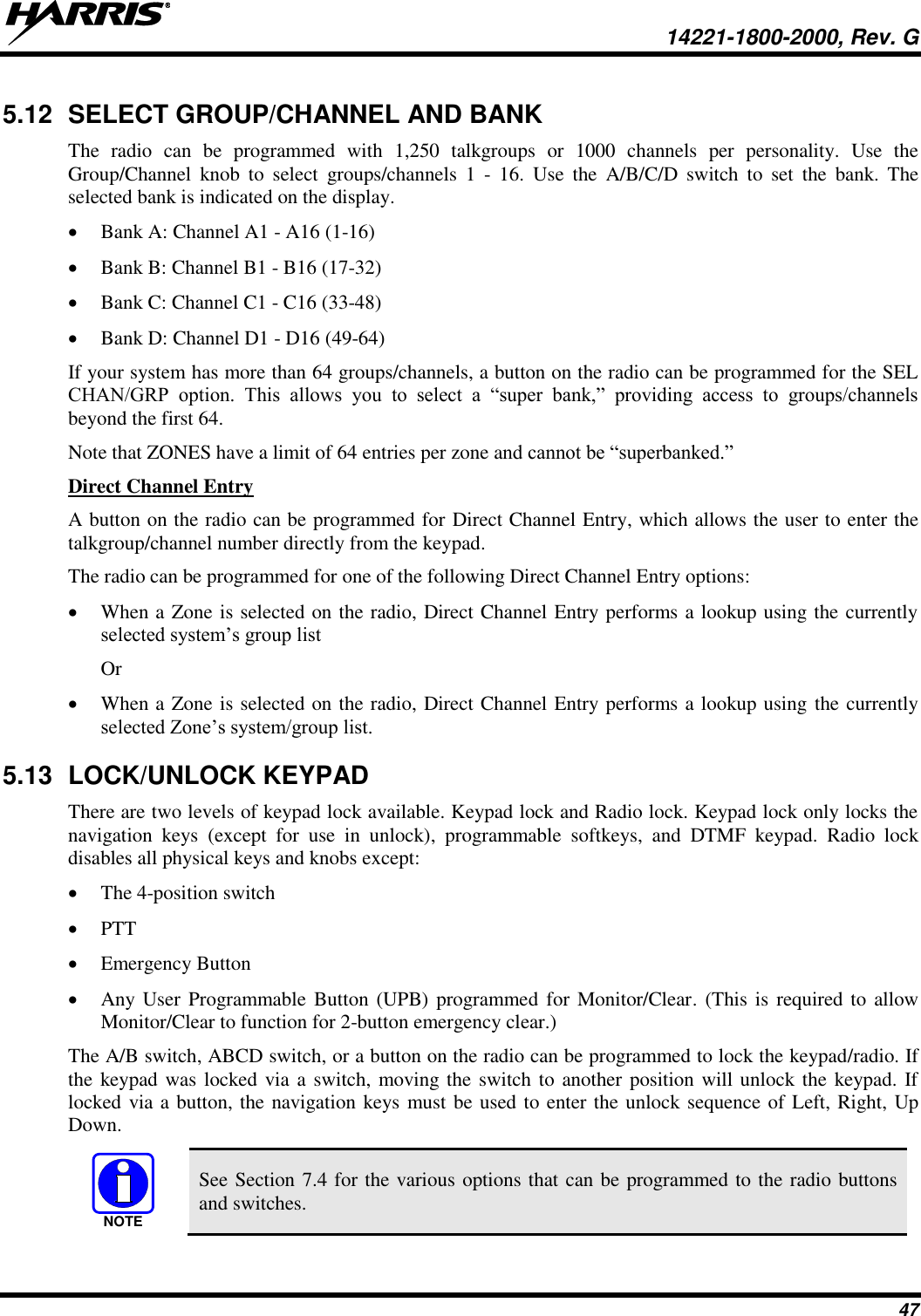
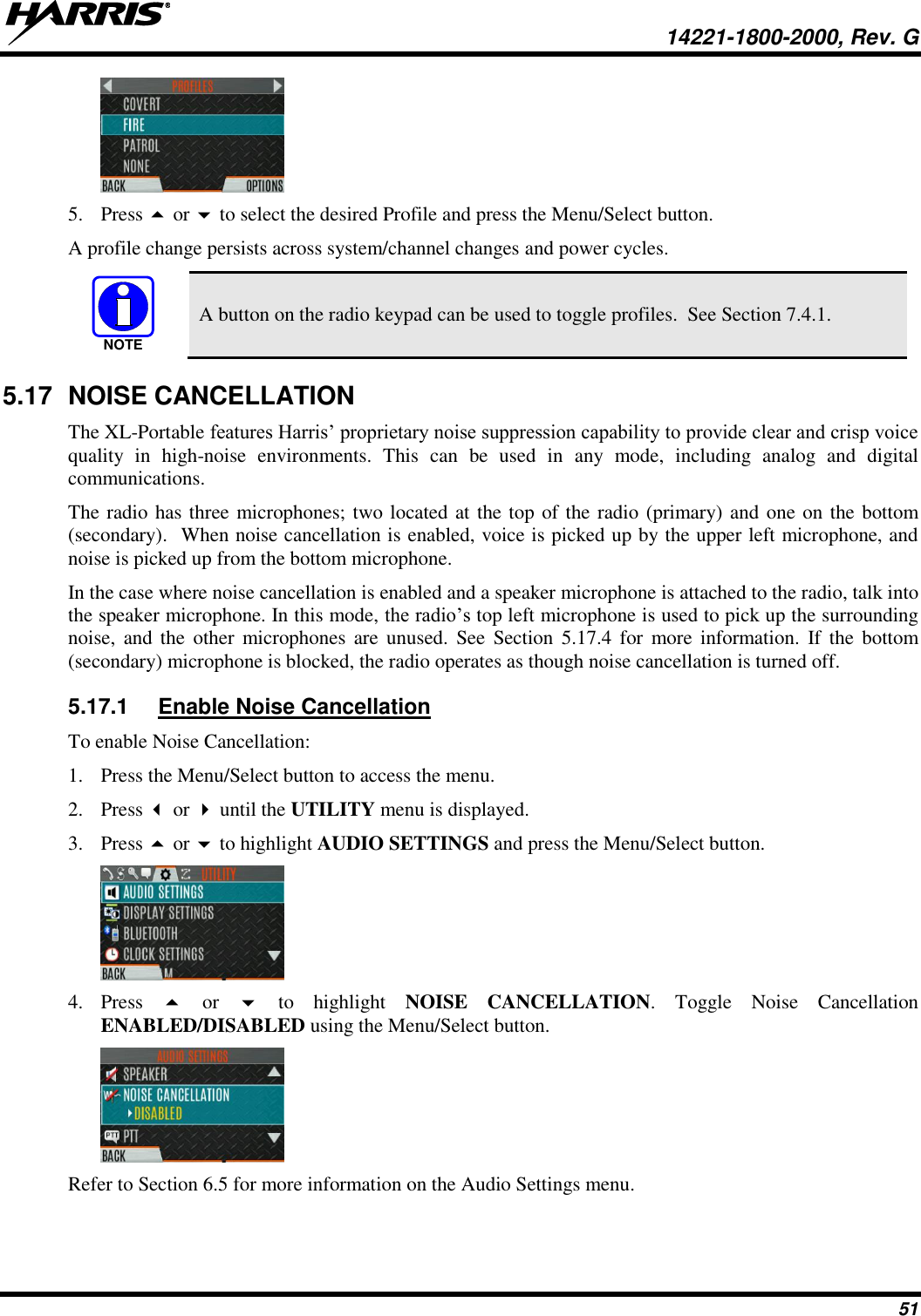
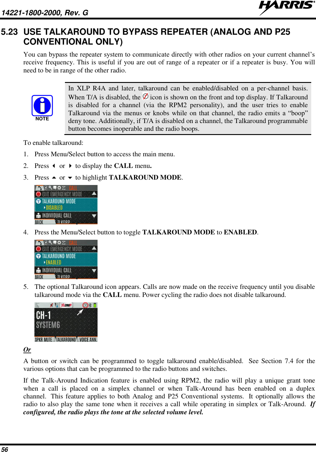
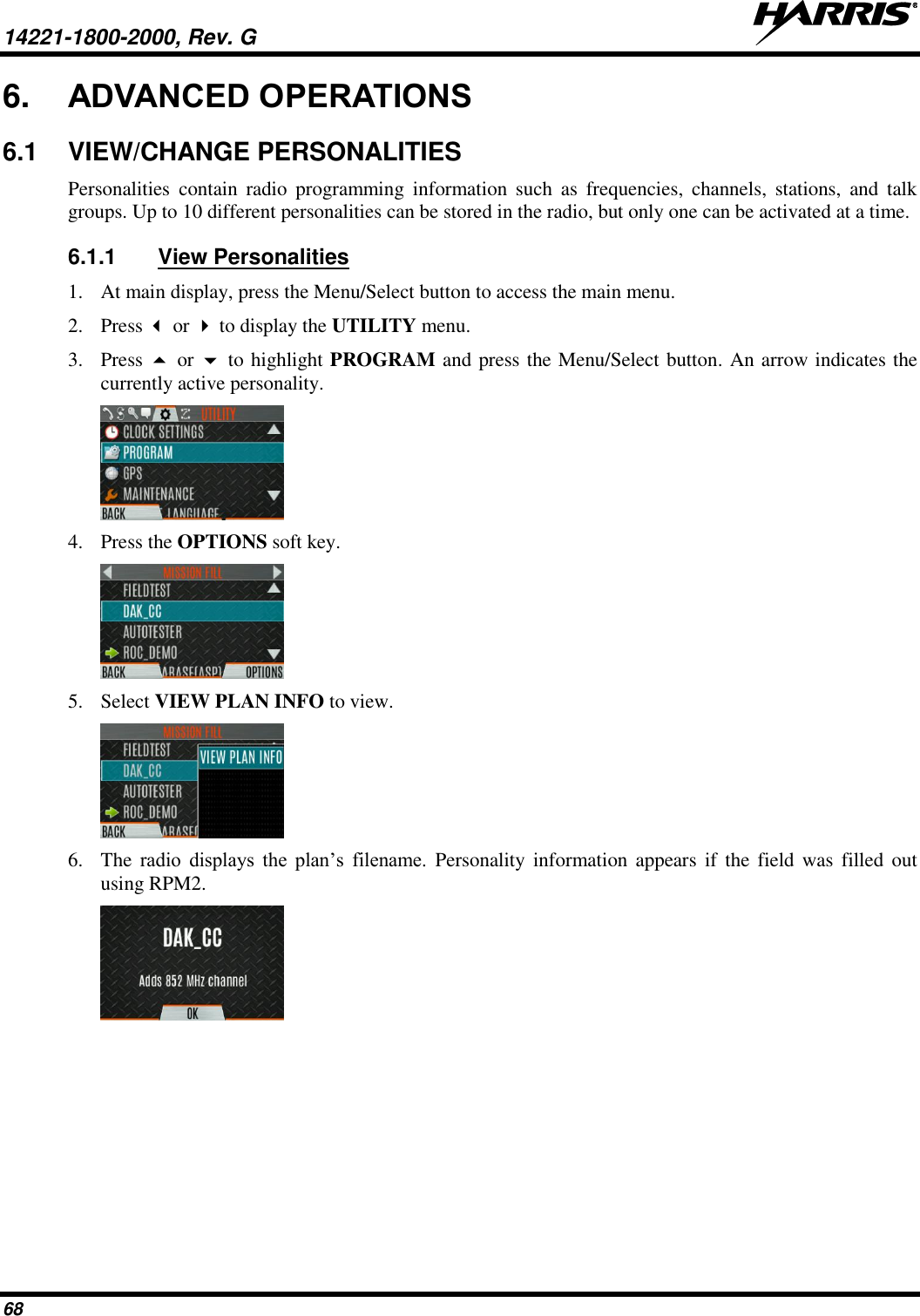
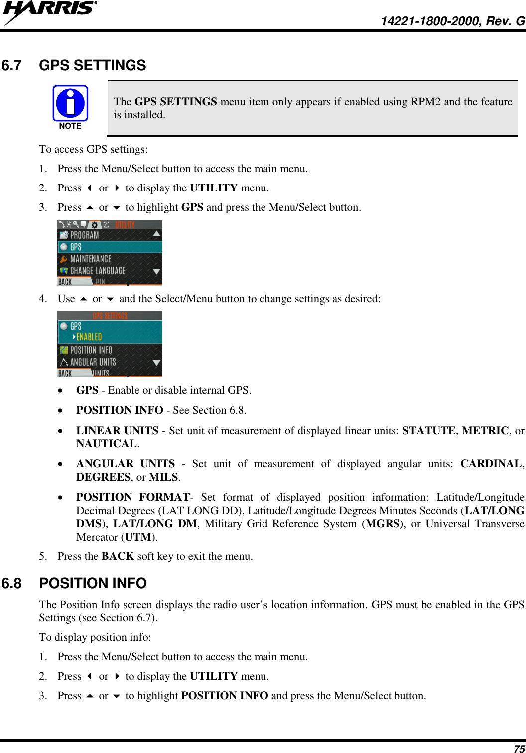
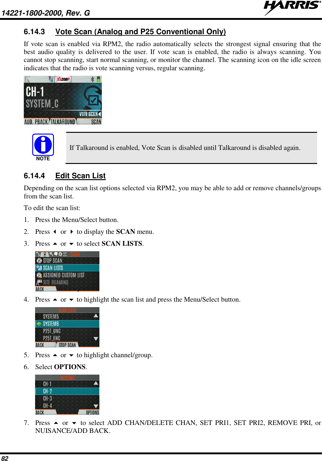
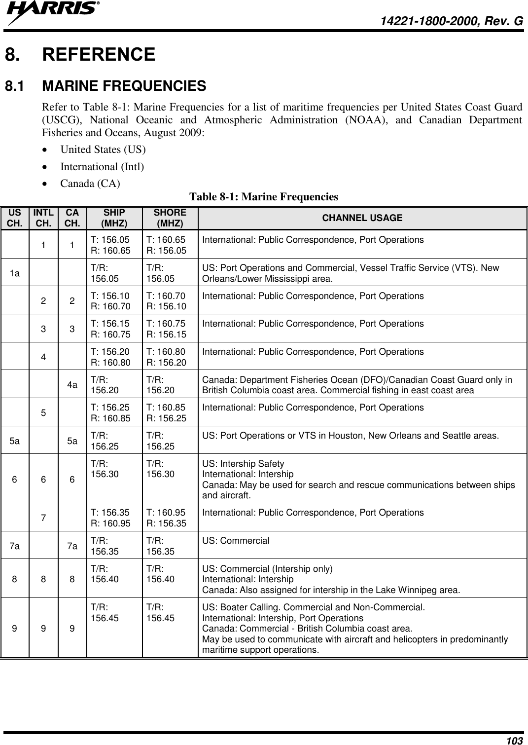
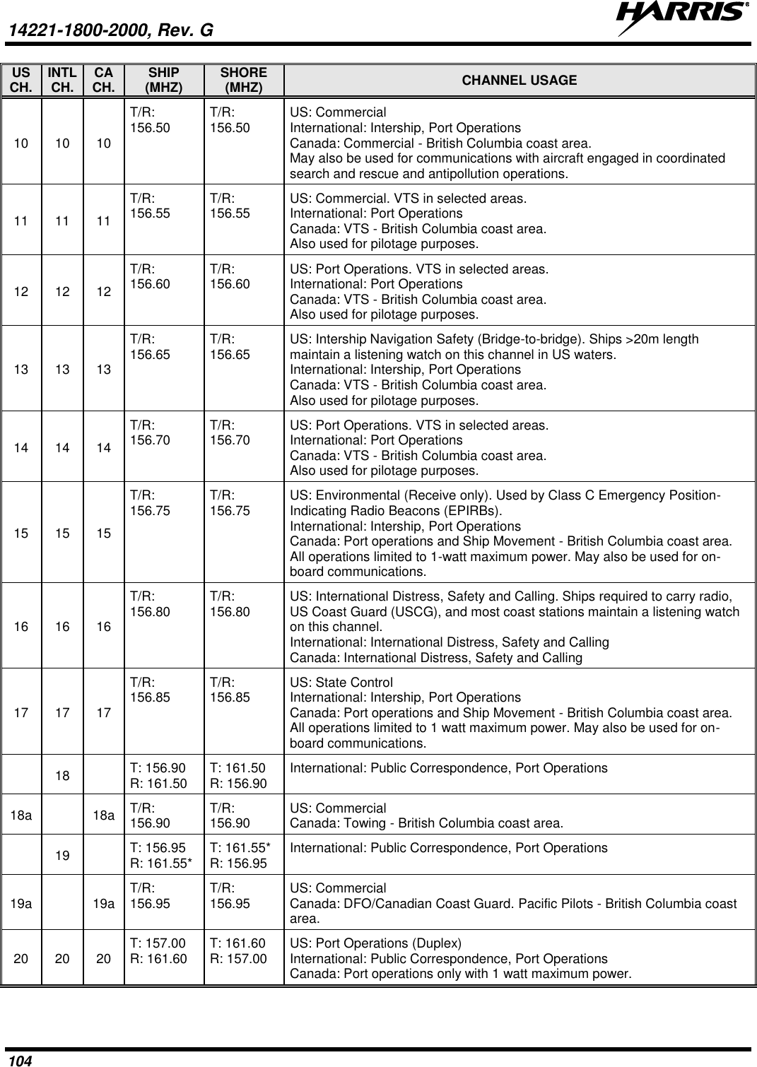
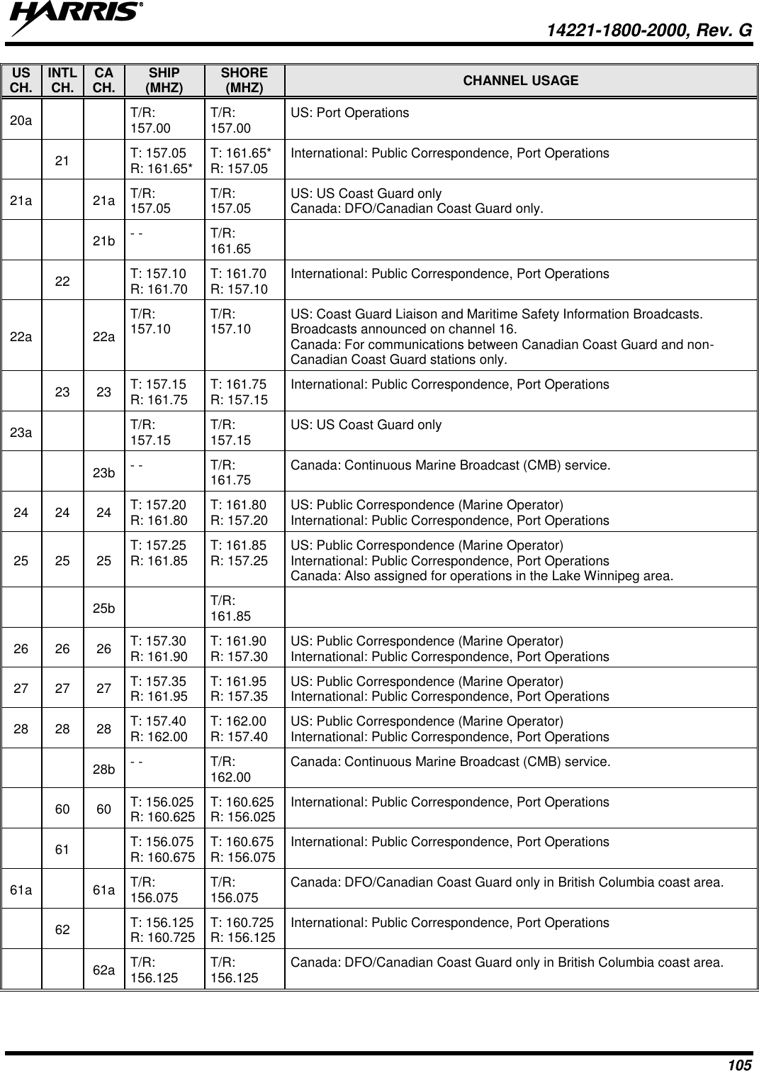
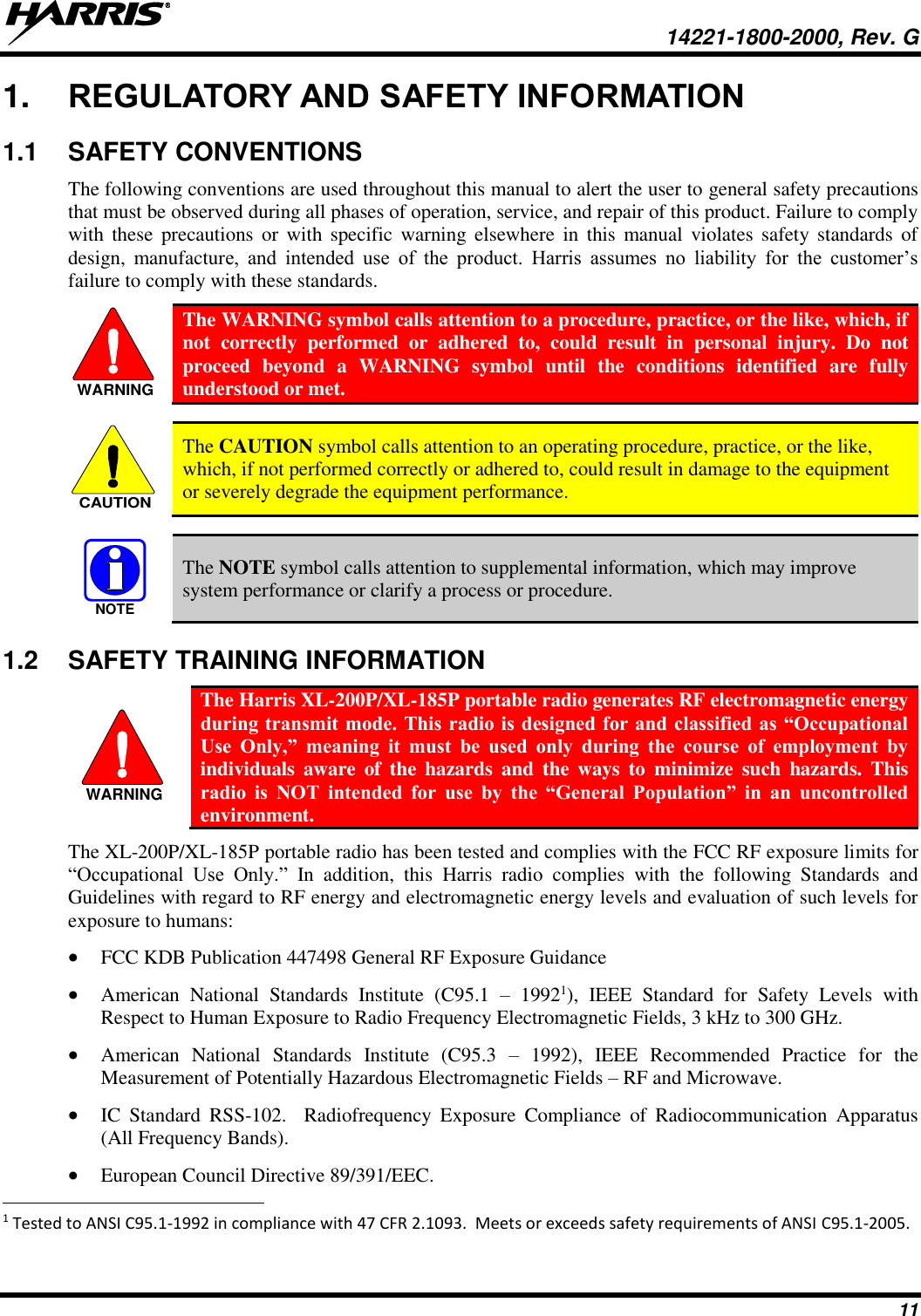
![14221-1800-2000, Rev. G 5 DECLARATION OF CONFORMITY Česky [Czech] Harris Corporation tímto prohlašuje, že tento XL-200P je ve shodě se základními požadavky a dalšími příslušnými ustanoveními směrnice 1999/5/ES. Dansk [Danish] Undertegnede Harris Corporation erklærer herved, at følgende udstyr XL-200P overholder de væsentlige krav og øvrige relevante krav i direktiv 1999/5/EF. Deutsch [German] Hiermit erklärt Harris Corporation, dass sich das Gerät XL-200P in Übereinstimmung mit den grundlegenden Anforderungen und den übrigen einschlägigen Bestimmungen der Richtlinie 1999/5/EG befindet. Eesti [Estonian] Käesolevaga kinnitab Harris Corporation seadme XL-200P vastavust direktiivi 1999/5/EÜ põhinõuetele ja nimetatud direktiivist tulenevatele teistele asjakohastele sätetele. English Hereby, Harris Corporation, declares that this XL-200P is in compliance with the essential requirements and other relevant provisions of Directive 1999/5/EC. Español [Spanish] Por medio de la presente Harris Corporation declara que el XL-200P cumple con los requisitos esenciales y cualesquiera otras disposiciones aplicables o exigibles de la Directiva 1999/5/CE. Ελληνική [Greek] ΜΕ ΤΗΝ ΠΑΡΟΥΣΑ Harris Corporation ΔΗΛΩΝΕΙ ΟΤΙ XL-200P ΣΥΜΜΟΡΦΩΝΕΤΑΙ ΠΡΟΣ ΤΙΣ ΟΥΣΙΩΔΕΙΣ ΑΠΑΙΤΗΣΕΙΣ ΚΑΙ ΤΙΣ ΛΟΙΠΕΣ ΣΧΕΤΙΚΕΣ ΔΙΑΤΑΞΕΙΣ ΤΗΣ ΟΔΗΓΙΑΣ 1999/5/ΕΚ. Français [French] Par la présente Harris Corporation déclare que l'appareil XL-200P est conforme aux exigences essentielles et aux autres dispositions pertinentes de la directive 1999/5/CE. Italiano [Italian] Con la presente Harris Corporation dichiara che questo XL-200P è conforme ai requisiti essenziali ed alle altre disposizioni pertinenti stabilite dalla direttiva 1999/5/CE. Latviski [Latvian] Ar šo Harris Corporation deklarē, XG 25P UHF-L (378-470 MHz), 7/800 (764-870MHz) atbilst Direktīvas 1999/5/EK būtiskajām prasībām un citiem ar to saistītajiem noteikumiem. Lietuvių [Lithuanian] Šiuo Harris Corporation deklaruoja, kad šis XL-200P atitinka esminius reikalavimus ir kitas 1999/5/EB Direktyvos nuostatas. Nederlands [Dutch] Hierbij verklaart Harris Corporation dat het toestel XL-200P in overeenstemming is met de essentiële eisen en de andere relevante bepalingen van richtlijn 1999/5/EG. Malti [Maltese] Hawnhekk, Harris Corporation, jiddikjara li dan XL-200P jikkonforma mal-ħtiġijiet essenzjali u ma provvedimenti oħrajn relevanti li hemm fid-Dirrettiva 1999/5/EC. Magyar [Hungarian] Alulírott, Harris Corporation nyilatkozom, hogy a XL-200P megfelel a vonatkozó alapvetõ követelményeknek és az 1999/5/EC irányelv egyéb elõírásainak. Polski [Polish] Niniejszym Harris Corporation oświadcza, że XL-200P jest zgodny z zasadniczymi wymogami oraz pozostałymi stosownymi postanowieniami Dyrektywy 1999/5/EC. Português [Portuguese] Harris Corporation declara que este XL-200P está conforme com os requisitos essenciais e outras disposições da Directiva 1999/5/CE. Slovensko [Slovenian] Harris Corporation izjavlja, da je ta XL-200P v skladu z bistvenimi zahtevami in ostalimi relevantnimi določili direktive 1999/5/ES. Slovensky [Slovak] Harris Corporation týmto vyhlasuje, že XL-200P spĺňa základné požiadavky a všetky príslušné ustanovenia Smernice 1999/5/ES. Suomi [Finnish] Harris Corporation vakuuttaa täten että XL-200P tyyppinen laite on direktiivin 1999/5/EY oleellisten vaatimusten ja sitä koskevien direktiivin muiden ehtojen mukainen. Svenska [Swedish] Härmed intygar Harris Corporation att denna XL-200P står I överensstämmelse med de väsentliga egenskapskrav och övriga relevanta bestämmelser som framgår av direktiv 1999/5/EG. Íslenska [Icelandic] Hér með lýsir Harris Corporation yfir því að XL-200P er í samræmi við grunnkröfur og aðrar kröfur, sem gerðar eru í tilskipun 1999/5/EC. Norsk [Norwegian] Harris Corporation erklærer herved at utstyret XL-200P er i samsvar med de grunnleggende krav og øvrige relevante krav i direktiv 1999/5/EF.](https://usermanual.wiki/HARRIS/TR-0144-E/User-Guide-3508071-Page-5.png)
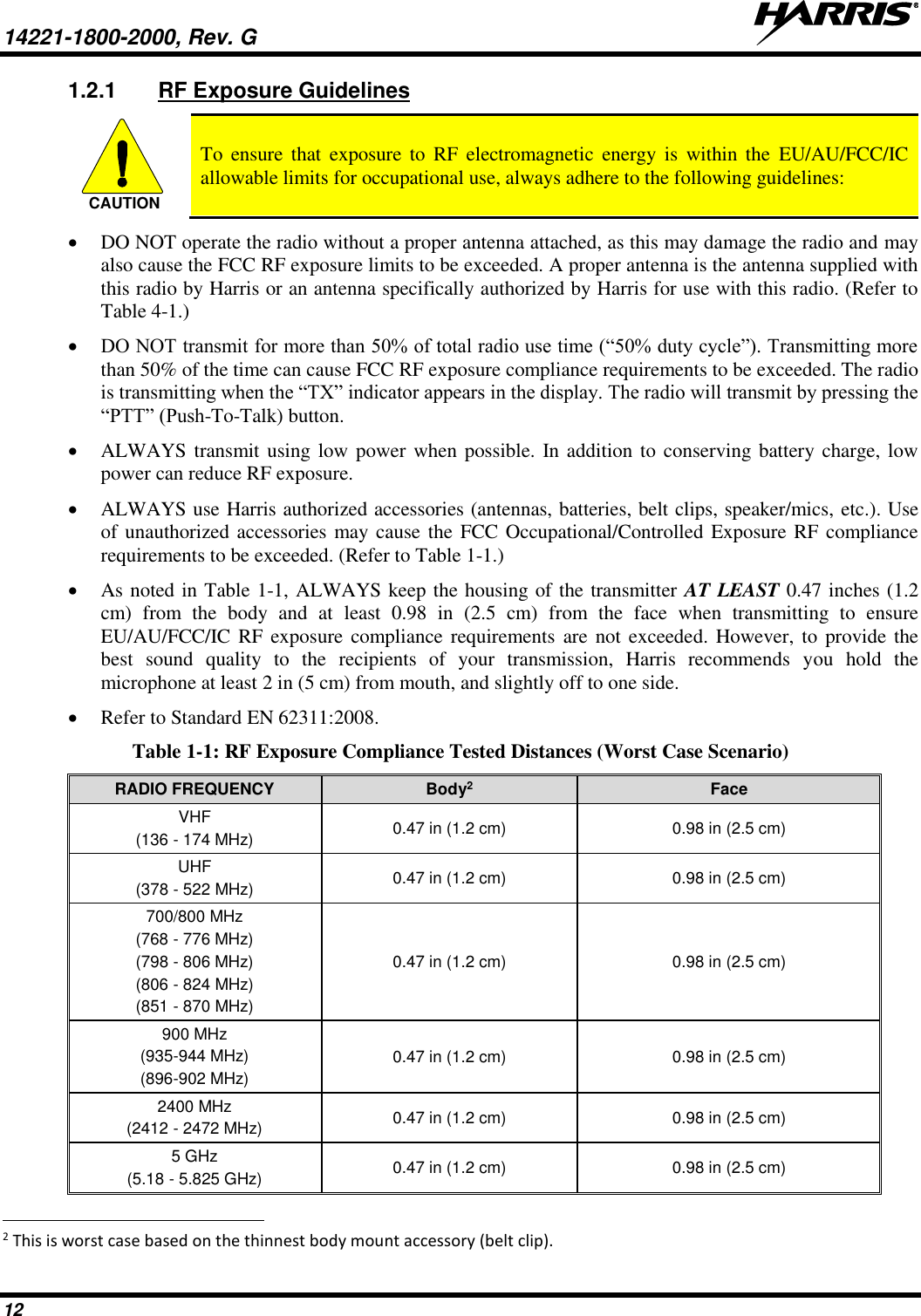
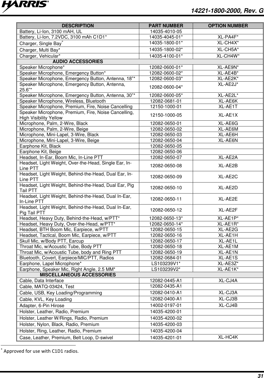
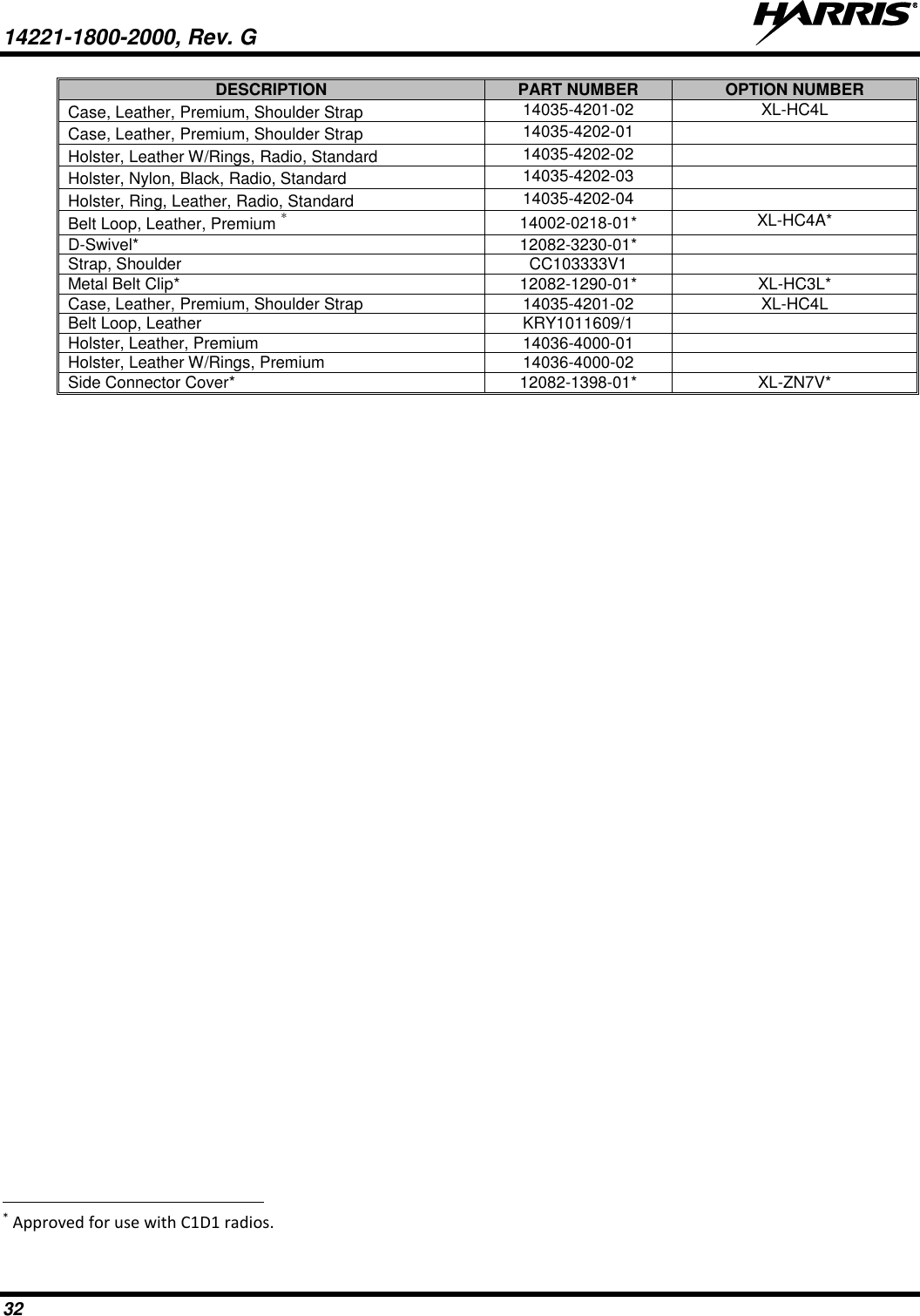
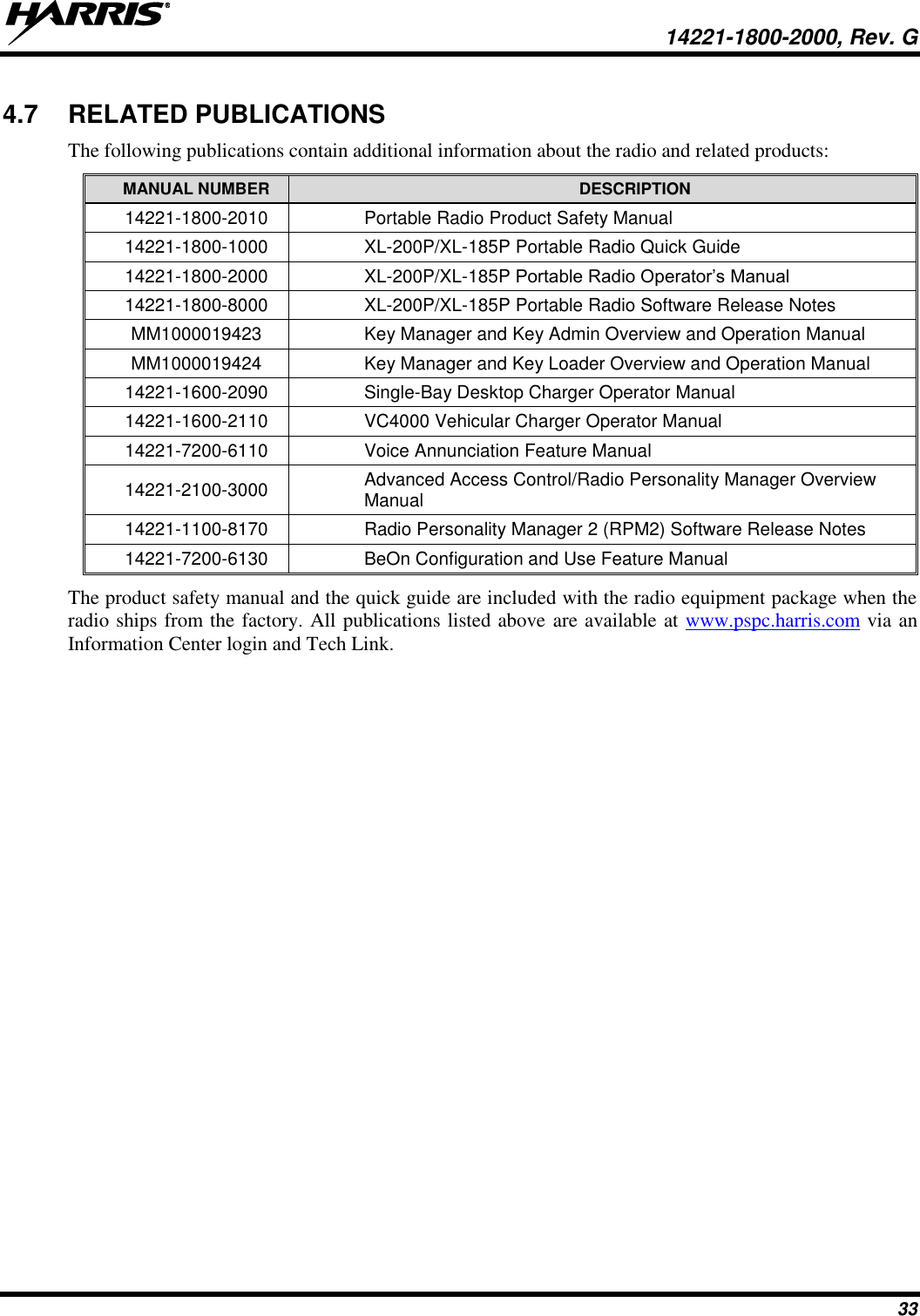
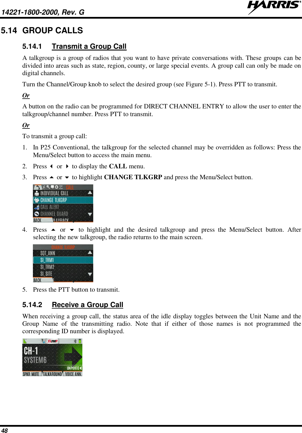
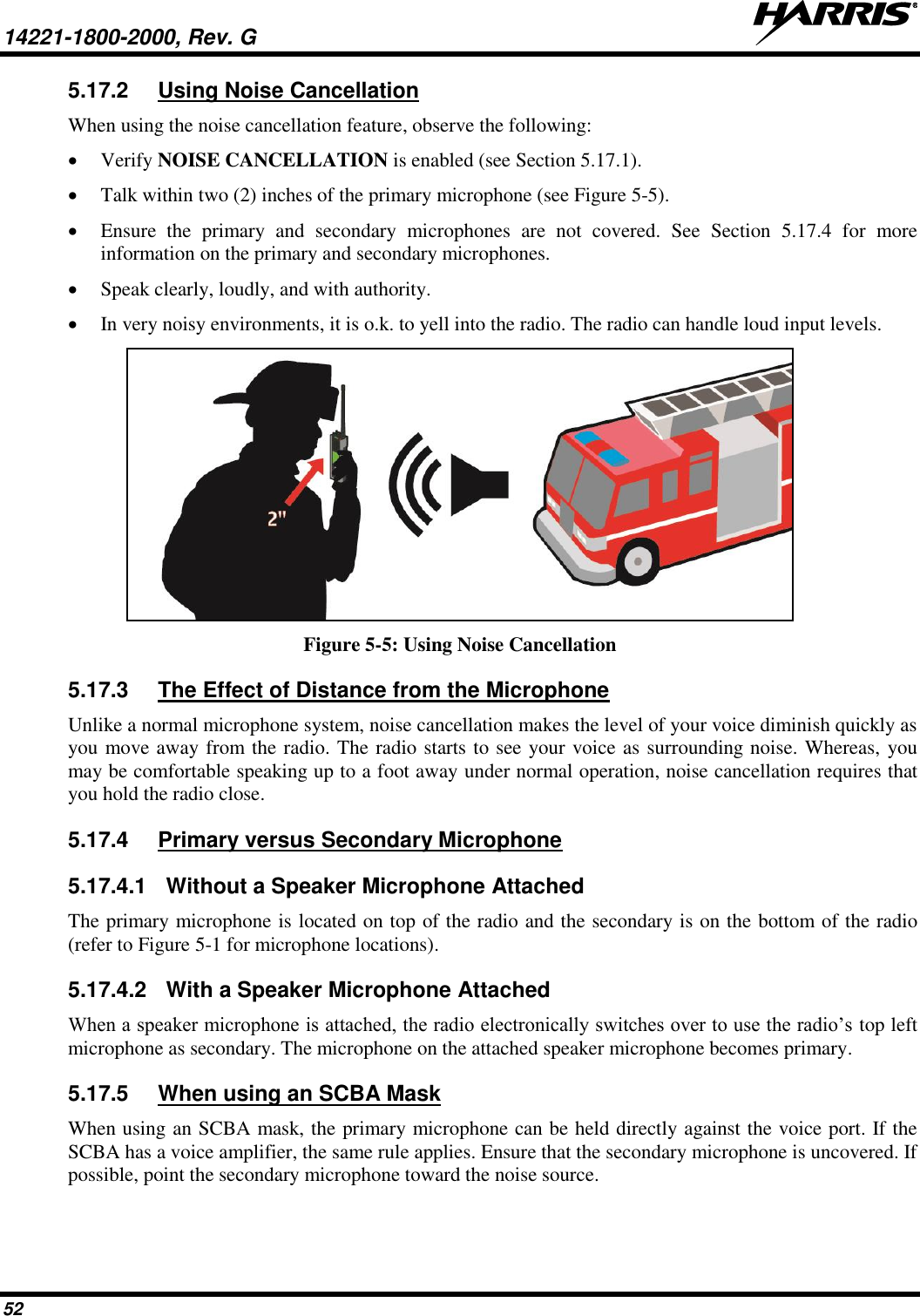
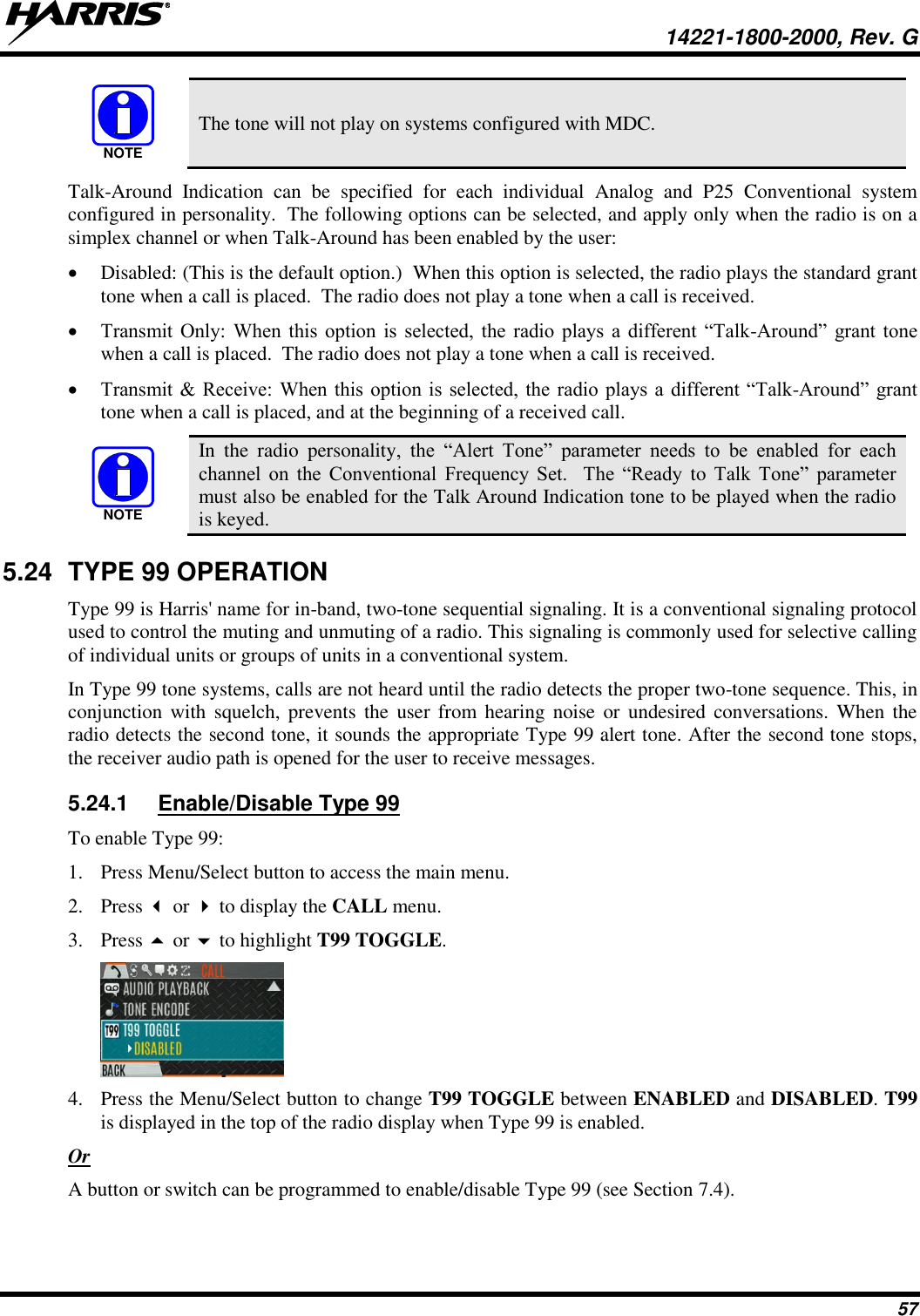
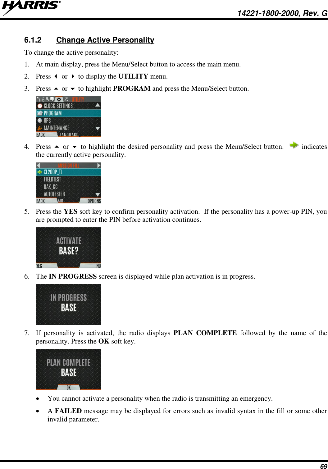
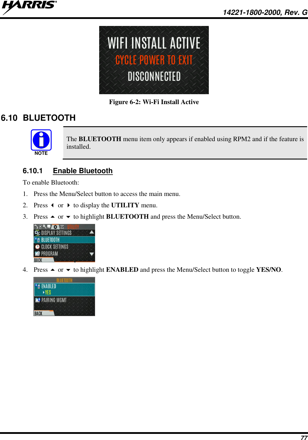
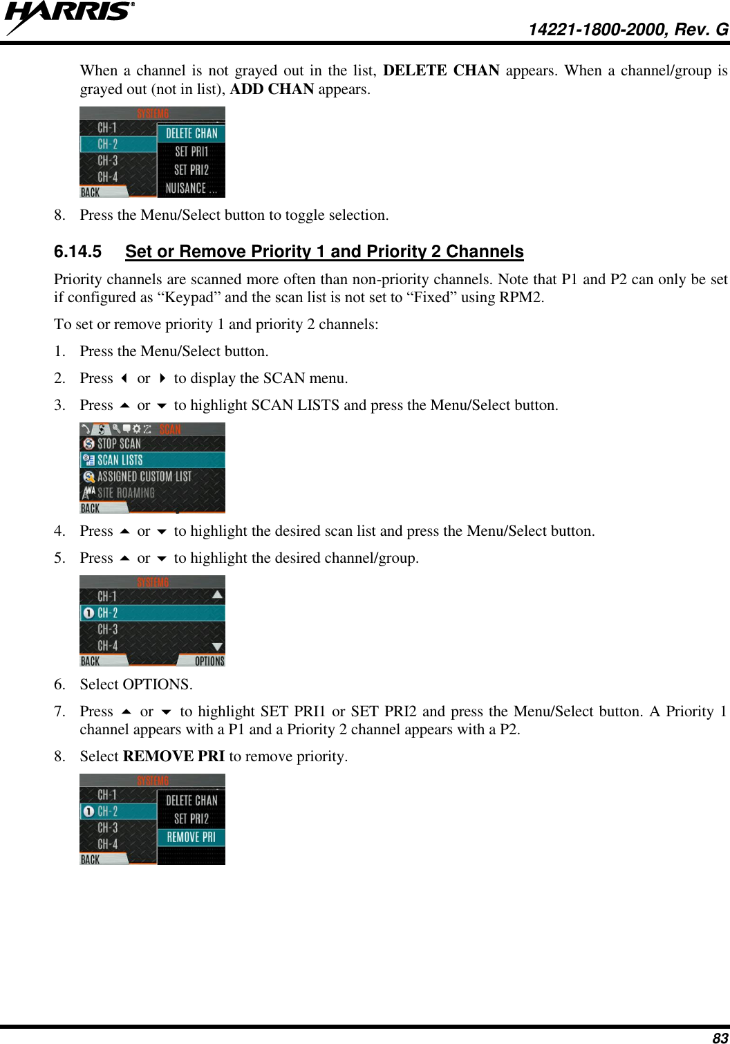
![14221-1800-2000, Rev. G 25 4. INTRODUCTION 4.1 DESCRIPTION The XL-Series portable radios provide the advanced connectivity that first responders require while addressing evolving voice and data communications. They meet MIL-STD-810G for durability and are certified to more stringent MIL-STD parameters for contamination by fluids and explosive atmospheres. XL portable radios support P25 Trunking, P25 Conventional, Enhanced Digital Access Communications System (EDACS), analog conventional, and BeOn® over a Wi-Fi® or LTE network. EDACS operation is not supported in UHF or VHF. Refer to Feature Manual 14221-7200-6130 for details on configuring and using BeOn on the XL Series radios. Radio features include: • Extremely Rugged – exceeds the standards of other radios on the market. • Multiband Operation – supports any combination of VHF, UHF, and 700/800 MHz frequencies. Also, allows different bands to be enabled for selected users. • Single-key DES Encryption – provides basic secure communications without having to buy the complete encryption option. • Instant Recall of Received Audio – allows user to replay the last transmission received to avoid unnecessary repetition. • Active Noise Cancellation – with three internal microphones to transmit intelligible audio from users in loud environments. • Built-in GPS – for location reporting and rapid response for emergencies. • Integrated Bluetooth® – for wireless interface to selected accessories. • Wi-Fi Connectivity – permits simple and easy radio software and personality updates. • Wi-Fi Access Point – Radios that include the LTE option can be configured via RPM2 to act as a Wi-Fi access point and/or router, providing access to broadband data for Wi-Fi devices. Refer to RPM2’s online help when configuring the radio for these functions. • Covert Mode – allows users to quickly configure the radio for operation in a covert environment. • Fully Programmable Keypad – each key can be programmed to a variety of functions. • 4-position switch – provides added configuration flexibility. • Unique User Interface – tools specially designed by first responders make radio operation simple and intuitive. An easy-to-read multi-color front display and a monochromatic top display with optional colored backlighting enhance communications for improved user safety. For optional accessories, refer to Table 4-1. Additional accessories may have been added since publication of this manual; contact Harris for more information. 4.2 STORAGE GUIDELINES Store your radio and batteries in a clean, cool (not exceeding 86 °F [+30 °C]), dry, and ventilated storage area. NOTE](https://usermanual.wiki/HARRIS/TR-0144-E/User-Guide-3508071-Page-25.png)