HARRIS TR-0145-E XL-200P, Multi-Band Portable Land Mobile Radio, Non-Rebanded User Manual
HARRIS CORPORATION XL-200P, Multi-Band Portable Land Mobile Radio, Non-Rebanded Users Manual
HARRIS >
Contents
- 1. Users Manual
- 2. User Manual
- 3. Users Manual Rev N
Users Manual

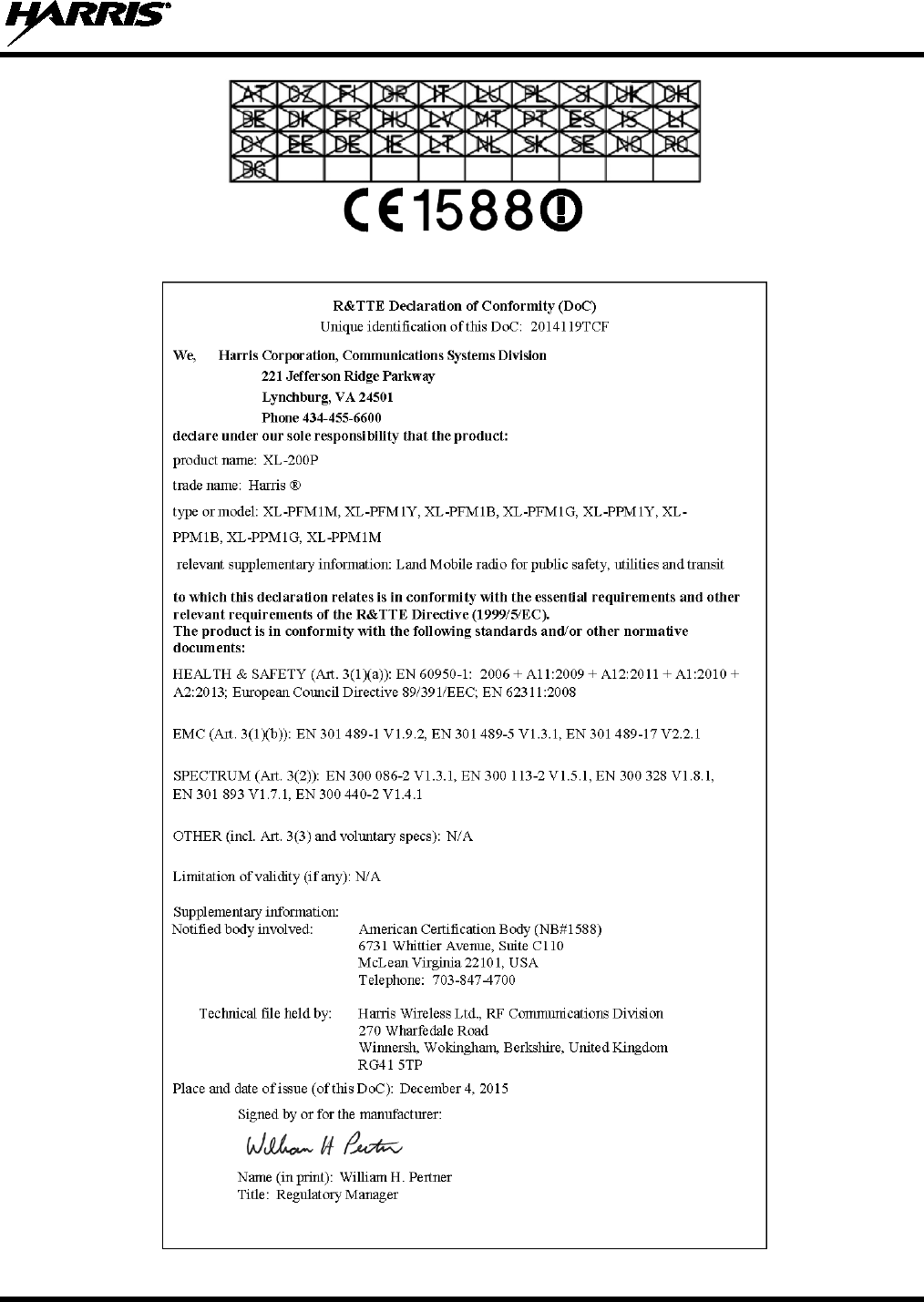
Rhein Tech Laboratories, Inc. Client: Harris Corporation
360 Herndon Parkway Model: XL-200P (International) Portable Radio
Suite 1400 IDs: - OWDTR-0145-E/3636B-0145
Herndon, VA 20170 Standards: FCC 22/74/80/90/IC RSS-119
http://www.rheintech.com Report #: 2015216TNF
477 of 487
Appendix P: Manual
Please refer to the following pages for the Operator’s Manual and the Product Safety Manual.

Operator’s Manual
14221-1800-2000
Rev. D, Feb/16
XL-200P
Full-Spectrum Multiband Radio

14221-1800-2000, Rev. D
2
MANUAL REVISION HISTORY
REV.
DATE
REASON FOR CHANGE
-
Sep/15
Initial release.
A
Sep/15
Added Section 3.
B
Nov/15
Added CE information.
C
Jan/16
Updated Declaration of Conformity. Added EU regulatory approval information (standards) and
EU RF exposure information.
D
Feb/16
Updated Table 1-1 and Tableau 2-1. Updated for XLP R2A and added LTE info.
Harris Corporation, Public Safety and Professional Communications (PSPC) Business continually evaluates its technical publications for
completeness, technical accuracy, and organization. You can assist in this process by submitting your comments and suggestions to the
following:
Harris Corporation fax your comments to: 1-434-455-6851
PSPC Business or
Technical Publications e-mail us at: PSPC_TechPubs@harris.com
221 Jefferson Ridge Parkway
Lynchburg, VA 24501
ACKNOWLEDGEMENT
This product was developed using GEOTRANS, a product of the National Geospatial Intelligence Agency and U.S. Army Engineering
Research and Development Center. Use of this software does not indicate endorsement or approval of the product by the Secretary of
Defense or the National Geospatial Intelligence Agency.
This device made under license under one or more of the following US patents: 4,590,473; 4,636,791; 5,148,482; 5,185,796; 5,271,017;
5,377,229; 4,716,407; 4,972,460; 5,502,767; 5,146,697; 5,164,986; 5,185,795.
The Advanced Multi-Band Excitation implementation 2 (AMBE+2) voice coding Technology embodied in this product is protected by
intellectual property rights including patent rights, copyrights and trade secrets of Digital Voice Systems, Inc. This voice coding
Technology is licensed solely for use within this Communications Equipment. The user of this Technology is explicitly prohibited from
attempting to extract, remove, decompile, reverse engineer, or disassemble the Object Code, or in any other way convert the Object Code
into a human-readable form. U.S. Patent Nos. #5,870,405, #5,826,222, #5,754,974, #5,701,390, #5,715,365, #5,649,050, #5,630,011,
#5,581,656, #5,517,511, #5,491,772, #5,247,579, #5,226,084 and #5,195,166.
CREDITS
Harris, assuredcommunications, Unity, VIDA, EDACS, NetworkFirst, and OpenSky are registered trademarks of Harris Corporation.
Bluetooth is a registered trademark of Bluetooth SIG, Inc.
Motorola is a registered trademark of Motorola, Inc.
AMBE is a registered trademark and IMBE, AMBE+, and AMBE+2 are trademarks of Digital Voice Systems, Inc.
Wi-Fi is a registered trademark of Wi-Fi Alliance.
All brand and product names are trademarks, registered trademarks, or service marks of their respective holders.
NOTICE!
The material contained herein is subject to U.S. export approval. No export or re-export is permitted without written approval from the U.S.
Government. Rated: EAR99; in accordance with U.S. Dept. of Commerce regulations 15CFR774, Export Administration Regulations.
Information and descriptions contained herein are the property of Harris Corporation. Such information and descriptions may not be copied
or reproduced by any means, or disseminated or distributed without the express prior written permission of Harris Corporation, PSPC
Business, 221 Jefferson Ridge Parkway, Lynchburg, VA 24501.
Repairs to this equipment should be made only by an authorized service technician or facility designated by the supplier. Any repairs,
alterations or substitutions of recommended parts made by the user to this equipment not approved by the manufacturer could void the
user's authority to operate the equipment in addition to the manufacturer's warranty.
This product conforms to the European Union WEEE Directive 2012/19/EU. Do not dispose of this product in a public
landfill. Take it to a recycling center at the end of its life.
This
manual is published by Harris Corporation
without any warranty. Improvements and changes to this manual necessitated by typographical errors,
inaccuracies of current information, or improvements to programs and/or equipment, may be made by
Harris Corporation
at any time and without notice.
Such changes will be incorporated into new editions of this manual. No part of this manual may be reproduced or transmitted in any form or by any means,
electronic or mechanical, including photocopying and recording, for
any purpose, without the express written permission of Harris Corporation.
Copyright © 2016 Harris Corporation.
14221-1800-2000, Rev. D
3
This device is a RF transceiver intended for land mobile radio applications. The device may have use restrictions, which require that the
national authority be contacted for any system licensing requirements, frequency use, allowable power level, etc.
14221-1800-2000, Rev. D
4
Česky
[Czech]
Harris Corporation tímto prohlašuje, že tento XL-200P je ve shodě se základními požadavky a
dalšími příslušnými ustanoveními směrnice 1999/5/ES.
Dansk
[Danish]
Undertegnede Harris Corporation erklærer herved, at følgende udstyr XL-200P overholder de
væsentlige krav og øvrige relevante krav i direktiv 1999/5/EF.
Deutsch
[German]
Hiermit erklärt Harris Corporation, dass sich das Gerät XL-200P in Übereinstimmung mit den
grundlegenden Anforderungen und den übrigen einschlägigen Bestimmungen der Richtlinie
1999/5/EG befindet.
Eesti
[Estonian]
Käesolevaga kinnitab Harris Corporation seadme XL-200P vastavust direktiivi 1999/5/EÜ
põhinõuetele ja nimetatud direktiivist tulenevatele teistele asjakohastele sätetele.
English Hereby, Harris Corporation, declares that this XL-200P is in compliance with the essential
requirements and other relevant provisions of Directive 1999/5/EC.
Español
[Spanish]
Por medio de la presente Harris Corporation declara que el XL-200P cumple con los requisitos
esenciales y cualesquiera otras disposiciones aplicables o exigibles de la Directiva 1999/5/CE.
Ελληνική
[Greek]
ΜΕ ΤΗΝ ΠΑΡΟΥΣΑ Harris Corporation ΔΗΛΩΝΕΙ ΟΤΙ XL-200P ΣΥΜΜΟΡΦΩΝΕΤΑΙ ΠΡΟΣ ΤΙΣ
ΟΥΣΙΩΔΕΙΣ ΑΠΑΙΤΗΣΕΙΣ ΚΑΙ ΤΙΣ ΛΟΙΠΕΣ ΣΧΕΤΙΚΕΣ ΔΙΑΤΑΞΕΙΣ ΤΗΣ ΟΔΗΓΙΑΣ 1999/5/ΕΚ.
Français
[French]
Par la présente Harris Corporation déclare que l'appareil XL-200P est conforme aux exigences
essentielles et aux autres dispositions pertinentes de la directive 1999/5/CE.
Italiano
[Italian]
Con la presente Harris Corporation dichiara che questo XL-200P è conforme ai requisiti
essenziali ed alle altre disposizioni pertinenti stabilite dalla direttiva 1999/5/CE.
Latviski
[Latvian]
Ar šo Harris Corporation deklarē, XG 25P UHF-L(378-470 MHz), 7/800 (764-870MHz) atbilst
Direktīvas 1999/5/EK būtiskajām prasībām un citiem ar to saistītajiem noteikumiem.
Lietuvių
[Lithuanian]
Šiuo Harris Corporation deklaruoja, kad šis XL-200P atitinka esminius reikalavimus ir kitas
1999/5/EB Direktyvos nuostatas.
Nederlands
[Dutch]
Hierbij verklaart Harris Corporation dat het toestel XL-200P in overeenstemming is met de
essentiële eisen en de andere relevante bepalingen van richtlijn 1999/5/EG.
Malti
[Maltese]
Hawnhekk, Harris Corporation, jiddikjara li dan XL-200P jikkonforma mal-ħtiġijiet essenzjali u
ma provvedimenti oħrajn relevanti li hemm fid-Dirrettiva 1999/5/EC.
Magyar
[Hungarian]
Alulírott, Harris Corporation nyilatkozom, hogy a XL-200P megfelel a vonatkozó alapvetõ
követelményeknek és az 1999/5/EC irányelv egyéb elõírásainak.
14221-1800-2000, Rev. D
5
Polski
[Polish]
Niniejszym Harris Corporation oświadcza, że XL-200P jest zgodny z zasadniczymi wymogami
oraz pozostałymi stosownymi postanowieniami Dyrektywy 1999/5/EC.
Português
[Portuguese]
Harris Corporation declara que este XL-200P está conforme com os requisitos essenciais e
outras disposições da Directiva 1999/5/CE.
Slovensko
[Slovenian]
Harris Corporation izjavlja, da je ta XL-200P v skladu z bistvenimi zahtevami in ostalimi
relevantnimi določili direktive 1999/5/ES.
Slovensky
[Slovak]
Harris Corporation týmto vyhlasuje, že XL-200P spĺňa základné požiadavky a všetky príslušné
ustanovenia Smernice 1999/5/ES.
Suomi
[Finnish]
Harris Corporation vakuuttaa täten että XL-200P tyyppinen laite on direktiivin 1999/5/EY
oleellisten vaatimusten ja sitä koskevien direktiivin muiden ehtojen mukainen.
Svenska
[Swedish]
Härmed intygar Harris Corporation att denna XL-200P står I överensstämmelse med de
väsentliga egenskapskrav och övriga relevanta bestämmelser som framgår av direktiv
1999/5/EG.
Íslenska
[Icelandic]
Hér með lýsir Harris Corporation yfir því að XL-200P er í samræmi við grunnkröfur og aðrar
kröfur, sem gerðar eru í tilskipun 1999/5/EC.
Norsk
[Norwegian]
Harris Corporation erklærer herved at utstyret XL-200P er i samsvar med de grunnleggende
krav og øvrige relevante krav i direktiv 1999/5/EF.

14221-1800-2000, Rev. D
6
TABLE OF CONTENTS
Section Page
1. REGULATORY AND SAFETY INFORMATION ........................................................................... 10
1.1 SAFETY CONVENTIONS ........................................................................................................ 10
1.2 SAFETY TRAINING INFORMATION .................................................................................... 10
1.2.1 RF Exposure Guidelines ................................................................................................ 11
1.2.2 Electromagnetic Interference/Compatibility .................................................................. 12
1.3 REGULATORY APPROVALS ................................................................................................. 12
1.3.1 Part 15 ............................................................................................................................ 12
1.3.2 Industry Canada ............................................................................................................. 12
1.4 OPERATING TIPS .................................................................................................................... 12
1.4.1 Efficient Radio Operation .............................................................................................. 12
1.4.2 Antenna Care and Replacement ..................................................................................... 13
1.4.3 Electronic Devices ......................................................................................................... 13
1.4.4 Aircraft ........................................................................................................................... 13
1.4.5 Electric Blasting Caps .................................................................................................... 13
1.4.6 Potentially Explosive Atmospheres ............................................................................... 13
2. RENSEIGNEMENTS SUR LA RÉGLEMENTATION ET SÉCURITÉ ....................................... 14
2.1 CONVENTIONS SUR LES SYMBOLES DE SÉCURITÉ ...................................................... 14
2.2 RENSEIGNEMENTS SUR LA FORMATION SUR LA SÉCURITÉ ...................................... 14
2.2.1 Directives sur l’exposition aux RF ................................................................................ 15
2.2.2 Interférence/Compatibilité Électromagnétique .............................................................. 16
2.3 INTERFÉRENCE DES RADIOFRÉQUENCES ....................................................................... 16
2.3.1 Partie 15 de la FCC ........................................................................................................ 16
2.3.2 Industrie Canada ............................................................................................................ 16
2.4 CONSEILS D’UTILISATION ................................................................................................... 16
2.4.1 Utilisation Efficace de la Radio ..................................................................................... 16
3. HAZARDOUS LOCATIONS .............................................................................................................. 19
4. INTRODUCTION ................................................................................................................................ 21
4.1 DESCRIPTION .......................................................................................................................... 21
4.2 STORAGE GUIDELINES ......................................................................................................... 21
4.3 BASIC SETUP ........................................................................................................................... 22
4.3.1 Assemble the Radio ....................................................................................................... 22
4.3.2 Removing the Battery .................................................................................................... 23
4.3.3 Removing the Optional Belt Clip .................................................................................. 23
4.4 UNIVERSAL DEVICE CONNECTOR ..................................................................................... 24
4.5 CLEANING ................................................................................................................................ 24
4.6 OPTIONS AND ACCESSORIES .............................................................................................. 26
5. BASIC OPERATION ........................................................................................................................... 28
5.1 XL-200P CONTROLS ............................................................................................................... 28
5.2 SOFT DTMF KEYPAD ............................................................................................................. 30
5.3 BEFORE FIRST USE ................................................................................................................. 30
5.4 POWER ON AND SET VOLUME ............................................................................................ 31
5.5 RADIO DISPLAYS .................................................................................................................... 31
5.5.1 Top Display ................................................................................................................... 31
5.5.2 Front Display ................................................................................................................. 31
5.6 STATUS MESSAGES ............................................................................................................... 33
5.7 MENU......................................................................................................................................... 33
5.8 PREDEFINED MENU LAYOUTS ............................................................................................ 36

14221-1800-2000, Rev. D
7
5.9 ALERT TONES.......................................................................................................................... 37
5.10 SELECT ZONE/SYSTEM ......................................................................................................... 38
5.11 SELECT GROUP/CHANNEL AND BANK ............................................................................. 39
5.12 LOCK/UNLOCK KEYPAD....................................................................................................... 39
5.13 GROUP CALLS ......................................................................................................................... 40
5.13.1 Transmit a Group Call ................................................................................................... 40
5.13.2 Receive a Group Call ..................................................................................................... 40
5.14 INDIVIDUAL CALLS ............................................................................................................... 41
5.14.1 Transmit an Individual Call ........................................................................................... 41
5.14.2 Receiving an Individual Call ......................................................................................... 41
5.15 PROFILES .................................................................................................................................. 42
5.16 NOISE CANCELLATION ......................................................................................................... 42
5.16.1 Enable Noise Cancellation ............................................................................................. 43
5.16.2 Using Noise Cancellation .............................................................................................. 43
5.16.3 The Effect of Distance from the Microphone ................................................................ 43
5.16.4 Primary versus Secondary Microphone ......................................................................... 44
5.16.5 When using an SCBA Mask .......................................................................................... 44
5.17 PTT OPTIONS ........................................................................................................................... 44
5.18 VOICE ANNUNCIATION ........................................................................................................ 44
5.19 ENABLE/DISABLE ENCRYPTION ........................................................................................ 45
5.20 TRANSMIT ENABLE/DISABLE ............................................................................................. 45
5.21 CHANNEL GUARD (ANALOG CONVENTIONAL ONLY) ................................................. 46
5.22 USE TALKAROUND TO BYPASS REPEATER (ANALOG AND P25 CONVENTIONAL
ONLY) ........................................................................................................................................ 47
5.23 TYPE 99 OPERATION .............................................................................................................. 48
5.23.1 Enable/Disable Type 99 ................................................................................................. 48
5.23.2 Disable After PTT.......................................................................................................... 48
5.23.3 Auto Reset ..................................................................................................................... 48
5.24 CALL ALERT (PAGE) .............................................................................................................. 49
5.24.1 Send Alert ...................................................................................................................... 49
5.24.2 Receive Alert ................................................................................................................. 49
5.25 DTMF ......................................................................................................................................... 49
5.26 AUDIO PLAYBACK ................................................................................................................. 49
5.27 START SCAN ............................................................................................................................ 50
5.28 STOP SCAN ............................................................................................................................... 51
5.29 MONITOR AND SQUELCH TYPES (CONVENTIONAL ONLY) ........................................ 52
5.30 NUISANCE DELETE ................................................................................................................ 53
5.31 EMERGENCY OPERATION .................................................................................................... 54
5.31.1 Declaring an Emergency Call ........................................................................................ 54
5.31.2 Receiving an Emergency Call ....................................................................................... 54
5.31.3 Stealth Emergency ......................................................................................................... 54
5.32 MDC-1200 (ANALOG CONVENTIONAL ONLY) ................................................................. 55
5.32.1 Normal PTT Operation .................................................................................................. 55
5.32.2 MDC PTT ID Receive Handling ................................................................................... 55
5.32.3 Emergency Declaration ................................................................................................. 55
6. ADVANCED OPERATIONS .............................................................................................................. 56
6.1 VIEW/CHANGE PERSONALITIES ......................................................................................... 56
6.1.1 View Personalities ......................................................................................................... 56
6.1.2 Change Active Personality ............................................................................................ 56
6.2 SITUATIONAL AWARENESS (SA) – P25 CONVENTIONAL ONLY ................................. 57

14221-1800-2000, Rev. D
8
6.3 USER-DEFINED ZONES/SYSTEMS ....................................................................................... 58
6.3.1 Command Tactical Zone ................................................................................................ 58
6.3.2 Mixed System Zone ....................................................................................................... 59
6.4 CH INFO MENU ........................................................................................................................ 60
6.5 AUDIO SETTINGS .................................................................................................................... 60
6.6 DISPLAY SETTINGS ................................................................................................................ 61
6.7 GPS SETTINGS ......................................................................................................................... 62
6.8 POSITION INFO ........................................................................................................................ 62
6.9 WI-FI .......................................................................................................................................... 63
6.10 BLUETOOTH ............................................................................................................................ 64
6.10.1 Enable Bluetooth ........................................................................................................... 64
6.10.2 Pair Devices ................................................................................................................... 64
6.11 CLOCK SETTINGS ................................................................................................................... 65
6.12 BATTERY SETTINGS .............................................................................................................. 66
6.13 SELECT LANGUAGE............................................................................................................... 66
6.14 SET UP SCAN ........................................................................................................................... 67
6.14.1 Default, Priority 1, and Priority 2 Channels .................................................................. 67
6.14.2 Trunked/Conventional Scanning ................................................................................... 67
6.14.3 Vote Scan (Analog and P25 Conventional Only) .......................................................... 68
6.14.4 Edit Scan List ................................................................................................................. 68
6.14.5 Set or Remove Priority 1 and Priority 2 Channels ......................................................... 69
6.14.6 Custom Scan Lists ......................................................................................................... 69
6.14.7 Wide Area System Scan (P25 Trunked Only) ............................................................... 71
6.15 RADIO STATUS ........................................................................................................................ 71
6.16 RADIO MESSAGE .................................................................................................................... 72
6.17 RADIO TEXTLINK ................................................................................................................... 72
6.17.1 Radio TextLink Messages ............................................................................................. 72
6.17.2 Radio TextLink Forms ................................................................................................... 73
6.17.3 View Received Messages .............................................................................................. 73
6.18 FAULTS/ALERTS ..................................................................................................................... 74
6.19 TONE ENCODE ........................................................................................................................ 75
6.20 ENCRYPTION ........................................................................................................................... 75
6.20.1 Create and Load Keys .................................................................................................... 75
6.20.2 Zeroize Keys from Radio ............................................................................................... 76
6.20.3 Protected Keys ............................................................................................................... 76
6.20.4 Global Encryption .......................................................................................................... 76
6.20.5 Select Keyset ................................................................................................................. 77
6.20.6 View Key List ................................................................................................................ 77
6.20.7 OTAR Configuration ..................................................................................................... 78
7. PROGRAMMING ................................................................................................................................ 79
7.1 PROGRAMMING VIA RPM2 .................................................................................................. 79
7.2 EDIT CHANNEL (ANALOG AND P25 CONVENTIONAL ONLY) ..................................... 79
7.3 OTAP .......................................................................................................................................... 81
7.4 PROGRAMMABLE BUTTONS AND SWITCHES ................................................................. 81
7.4.1 Programmable Buttons .................................................................................................. 81
7.4.2 Programmable A/B (Ø/O) Switch.................................................................................. 82
7.4.3 Programmable A/B/C/D Switch .................................................................................... 83
7.5 PROGRAMMABLE ICONS ...................................................................................................... 84
7.5.1 Top display .................................................................................................................... 84
7.5.2 Front display .................................................................................................................. 85

14221-1800-2000, Rev. D
9
8. REFERENCE ........................................................................................................................................ 86
8.1 MARINE FREQUENCIES ........................................................................................................ 86
8.2 NARROWBANDING ................................................................................................................ 91
9. GLOSSARY .......................................................................................................................................... 92
10. BASIC TROUBLESHOOTING .......................................................................................................... 95
10.1 ERROR MESSAGES ................................................................................................................. 95
10.2 OTAR ERRORS/INFORMATION ............................................................................................ 96
11. TECHNICAL ASSISTANCE .............................................................................................................. 97
12. WARRANTY ........................................................................................................................................ 97
APPENDIX A WI-FI PROGRAMMING ........................................................................................... 98
LIST OF FIGURES
Page
Figure 4-1: Radio Assembly .......................................................................................................................... 22
Figure 4-2: Remove the Battery ..................................................................................................................... 23
Figure 4-3: Remove Belt Clip ........................................................................................................................ 23
Figure 4-4: Universal Device Connector ....................................................................................................... 24
Figure 5-1: XL-200P Controls ....................................................................................................................... 28
Figure 5-2: Using the Soft DTMF Keypad .................................................................................................... 30
Figure 5-3: Top Display ................................................................................................................................. 31
Figure 5-4: Sample Idle Front Display .......................................................................................................... 31
Figure 5-5: Using Noise Cancellation ............................................................................................................ 43
Figure 6-1: Enabling Wi-Fi ............................................................................................................................ 63
Figure 6-2: Wi-Fi Install Active ..................................................................................................................... 63
Figure 12-1: Enable WIFI in RPM 2 ............................................................................................................. 98
Figure 12-2: Enable Wi-Fi on XL-200P ........................................................................................................ 99
Figure 12-3: RPM2 Network Configuration Screen .................................................................................... 100
LIST OF TABLES
Page
Table 1-1: RF Exposure Compliance Testing Distances ............................................................................... 11
Tableau 2-1 : Distances de test de conformité des expositions aux RF ......................................................... 15
Table 4-1: Options and Accessories ............................................................................................................... 26
Table 5-1: XL-200P Controls, Indicators, and Connectors ............................................................................ 28
Table 5-2: Radio Icons ................................................................................................................................... 32
Table 5-3: Status Messages ............................................................................................................................ 33
Table 5-4: Menu Navigation ......................................................................................................................... 33
Table 5-5: Predefined Menu Layouts ............................................................................................................. 36
Table 5-6: Alert Tones ................................................................................................................................... 37
Table 7-1: Valid Frequencies ......................................................................................................................... 81
Table 7-2: Programmable Button Options ..................................................................................................... 81
Table 7-3: Programmable Ø/O Switch Options ............................................................................................. 82
Table 7-4: Single-Instance Features ............................................................................................................... 83
Table 7-5: Indexed Features ........................................................................................................................... 84
Table 8-1: Marine Frequencies ...................................................................................................................... 86
Table 10-1: Displayed Error Messages, Reasons, and Resolutions .............................................................. 95
14221-1800-2000, Rev. D
10
1. REGULATORY AND SAFETY INFORMATION
1.1 SAFETY CONVENTIONS
The following conventions are used throughout this manual to alert the user to general safety precautions
that must be observed during all phases of operation, service, and repair of this product. Failure to comply
with these precautions or with specific warning elsewhere in this manual violates safety standards of
design, manufacture, and intended use of the product. Harris assumes no liability for the customer’s
failure to comply with these standards.
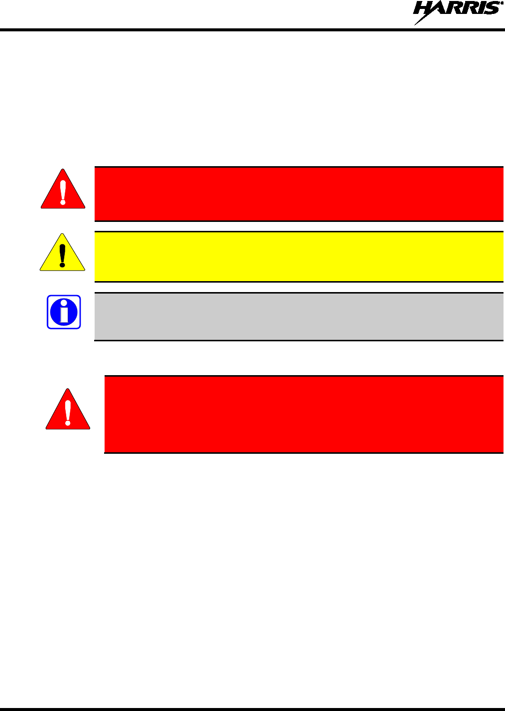
The WARNING symbol calls attention to a procedure, practice, or the like, which, if
not c
orrectly performed or adhered to, could result in personal injury. Do not
proceed beyond a WARNING symbol until the conditions identified are fully
understood or met.
The CAUTION symbol calls attention to an operating procedure, practice, or the like,
which, if not performed correctly or adhered to, could result in damage to the equipment
or severely degrade the equipment performance.
The NOTE symbol calls attention to supplemental information, which may improve
system performance or clarify a process or procedure.
1.2 SAFETY TRAINING INFORMATION
The Harris XL-200P portable radio generates RF electromagnetic energy during
transmit mode. This radio is designed for and classified as “Occupational Use
Only,” meaning it must be used only during the co
urse of employment by
individuals aware of the hazards and the ways to minimize such hazards. This
radio is NOT intended for use by the “General Population” in an uncontrolled
environment.
The XL-200P portable radio has been tested and complies with the FCC RF exposure limits for
“Occupational Use Only.” In addition, this Harris radio complies with the following Standards and
Guidelines with regard to RF energy and electromagnetic energy levels and evaluation of such levels for
exposure to humans:
• FCC OET Bulletin 65 Edition 97-01 Supplement C, Evaluating Compliance with FCC Guidelines for
Human Exposure to Radio Frequency Electromagnetic Fields.
• American National Standards Institute (C95.1 – 1992), IEEE Standard for Safety Levels with Respect
to Human Exposure to Radio Frequency Electromagnetic Fields, 3 kHz to 300 GHz.
• American National Standards Institute (C95.3 – 1992), IEEE Recommended Practice for the
Measurement of Potentially Hazardous Electromagnetic Fields – RF and Microwave.
• IC Standard RSS-102. Radiofrequency Exposure Compliance of Radiocommunication Apparatus
(All Frequency Bands).
• European Council Directive 89/391/EEC.
WARNING
CAUTION
NOTE
WARNING
14221-1800-2000, Rev. D
11
1.2.1 RF Exposure Guidelines
To ensure that exposure to RF electromagnetic energy is within the EU/AU/FCC/IC
allowable limits for occupational use, always adhere to the following guidelines:
• DO NOT operate the radio without a proper antenna attached, as this may damage the radio and may
also cause the FCC RF exposure limits to be exceeded. A proper antenna is the antenna supplied with
this radio by Harris or an antenna specifically authorized by Harris for use with this radio. (Refer to
Table 4-1.)
• DO NOT transmit for more than 50% of total radio use time (“50% duty cycle”). Transmitting more
than 50% of the time can cause FCC RF exposure compliance requirements to be exceeded. The radio
is transmitting when the “TX” indicator appears in the display. The radio will transmit by pressing the
“PTT” (Push-To-Talk) button.
• ALWAYS transmit using low power when possible. In addition to conserving battery charge, low
power can reduce RF exposure.
• ALWAYS use Harris authorized accessories (antennas, batteries, belt clips, speaker/mics, etc). Use of
unauthorized accessories may cause the FCC Occupational/Controlled Exposure RF compliance
requirements to be exceeded. (Refer to Table 1-1.)
• As noted in Table 1-1, ALWAYS keep the housing of the transmitter AT LEAST 0.47 inches (1.2
cm) from the body and at least 0.98 in (2.5 cm) from the face when transmitting to ensure
EU/AU/FCC/IC RF exposure compliance requirements are not exceeded. However, to provide the
best sound quality to the recipients of your transmission, Harris recommends you hold the
microphone at least 2 in (5 cm) from mouth, and slightly off to one side.
• Refer to Standard EN 62311:2008.
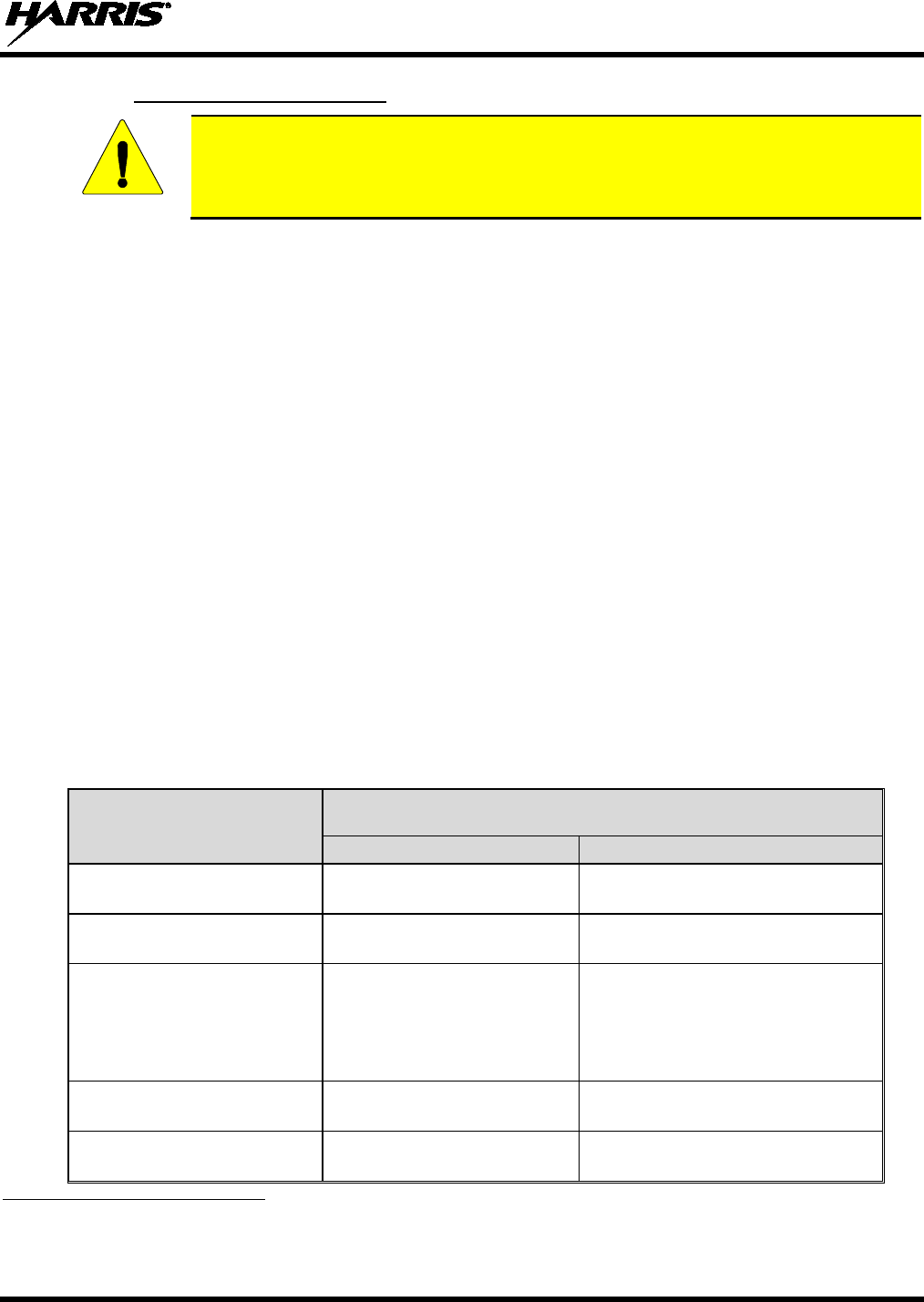
Table 1-1: RF Exposure Compliance Testing Distances1
RADIO FREQUENCY
TESTED DISTANCES
(worst case scenario)
Body2 Face
VHF
(136 - 174 MHz) 0.47 in (1.2 cm) 0.98 in (2.5 cm)
UHF
(378 - 522 MHz) 0.47 in (1.2 cm) 0.98 in (2.5 cm)
700/800 MHz
(768 - 776 MHz)
(798 - 806 MHz)
(806 - 824 MHz)
(851 - 870 MHz)
0.47 in (1.2 cm) 0.98 in (2.5 cm)
2400 MHz
(2412 - 2472 MHz) 0.47 in (1.2 cm) 0.98 in (2.5 cm)
5 GHz
(5.18 - 5.825 GHz) 0.47 in (1.2 cm) 0.98 in (2.5 cm)
1 Minimum safe operating distances for the radio are based on the Harmonized Standards and SAR evaluation.
2 This is worst case based on the thinnest body mount accessory (belt clip).
CAUTION

14221-1800-2000, Rev. D
12
The information in this section provides the information needed to make the user aware of RF exposure,
and what to do to assure that this radio operates within the FCC RF exposure limits.
1.2.2 Electromagnetic Interference/Compatibility
During transmissions, this Harris radio generates RF energy that can possibly cause interference with
other devices or systems. To avoid such interference, turn off the radio in areas where signs are posted to
do so. DO NOT operate the transmitter in areas that are sensitive to electromagnetic radiation such as
hospitals, aircraft, and blasting sites.
1.3 REGULATORY APPROVALS
1.3.1 Part 15
This device complies with Part 15 of the FCC Rules. Operation is subject to the following two conditions:
1. This device may not cause harmful interference, and
2. This device must accept any interference received, including interference that may cause undesired
operation.
1.3.2 Industry Canada
This device complies with Industry Canada license-exempt RSS standard(s). Operation is subject to the
following two conditions: (1) this device may not cause interference, and (2) this device must accept any
interference, including interference that may cause undesired operation of the device.
1.4 OPERATING TIPS
Antenna location and condition are important when operating a portable radio. Operating the radio in
low-lying areas or terrain, under power lines or bridges, inside of a vehicle, or in a metal framed building
can severely reduce the range of the unit. Mountains can also reduce the range of the unit.
In areas where transmission or reception is poor, some improvement may be obtained by ensuring that the
antenna is vertical. Moving a few yards in another direction or moving to a higher elevation may also
improve communications. Vehicular operation can be aided with the use of an externally mounted
antenna.
Battery condition is another important factor in the trouble free operation of a portable radio. Always
properly charge the battery.
1.4.1 Efficient Radio Operation
Keep the antenna in a vertical position when receiving or transmitting a message.
Do NOT hold onto the antenna when the radio is powered on!
WARNING
14221-1800-2000, Rev. D
13
1.4.2 Antenna Care and Replacement
Do not use the portable radio with a damaged or missing antenna. A minor burn
may result if a damaged antenna comes into contact with the skin. Replace a
damaged antenna immediately. Operating a portable radio with the antenna missing
could cause personal injury, damage the radio, and may violate FCC regulations.
Use only the supplied or approved antenna. Unauthorized antennas, modifications, or
attachments could cause damage to the radio unit and may violate FCC regulations. (Refer
to Table 4-1.)
1.4.3 Electronic Devices
RF energy from portable radios may affect some electronic equipment. Most modern
electronic equipment in cars, hospitals, homes, etc. is shielded from RF energy. However,
in areas in which you are instructed to turn off two-way radio equipment, always observe
the rules. If in doubt, turn it off!
1.4.4 Aircraft
• Always turn off a portable radio before boarding any aircraft!
• Use it on the ground only with crew permission.
• DO NOT use while in-flight!!
1.4.5 Electric Blasting Caps
To prevent accidental detonation of electric blasting caps, DO NOT use two-way
radios within 1000 feet of blasting operations. Always obey the "Turn Off Two-Way
Radios" signs posted where electric blasting caps are being used. (OSHA Standard:
1926.900)
1.4.6 Potentially Explosive Atmospheres
Areas with potentially explosive atmospheres are often, but not always, clearly
marked. These may be fuelling areas, such as gas stations, fuel or chemical transfer
or storage facilities, and areas where the air contains chemicals or particles, such as
grain, dust, or metal powders.
Sparks in such areas could cause an explosion or fire resulting in bodily injury or
even death.
Turn off two-way radios when in any area with a potentially explosive atmosphere. It
is rare, but not impossible that a radio or its accessories could generate sparks.
WARNING
CAUTION
CAUTION
WARNING
WARNING
WARNING
14221-1800-2000, Rev. D
14
2. RENSEIGNEMENTS SUR LA RÉGLEMENTATION ET
SÉCURITÉ
2.1 CONVENTIONS SUR LES SYMBOLES DE SÉCURITÉ
Les conventions suivantes sont utilisées dans le présent manuel pour avertir l’utilisateur des précautions générales de
sécurité qui doivent être observées pendant toutes les phases d’opération, d’entretien et de réparation de ce produit.
Le non-respect de ces précautions ou d’avertissements précisés ailleurs enfreint les normes de sécurité de la
conception, de la fabrication et de l’utilisation prévue du produit. Harris n’assume aucune responsabilité pour le
non-respect de ces normes par le client.
MISE EN GARDE
Le symbole MISE EN GARDE attire l’attention sur une procédure ou une
pratique qui, si elle n’est pas
correctement effectuée ou observée, pourrait
entraîner une blessure personnelle. Ne pas poursuivre au-delà d’un symbole de
MISE EN GARDE avant que les conditions identifiées soient complètement
comprises ou satisfaites.
AVERTISSEMENT
Le symbole AVERTISSEMENT attire l’attention sur une procédure ou une pratique
opérationnelle qui, si elle n’est pas correctement effectuée ou observée, pourrait
entraîner un bris d’équipement ou une importante baisse de rendement de l’équipement.
REMARQUE
Le symbole REMARQUE attire l’attention sur des renseignements supplémentaires qui
peuvent améliorer le rendement du système ou clarifier un processus ou une procédure.
2.2 RENSEIGNEMENTS SUR LA FORMATION SUR LA SÉCURITÉ
MISE EN GARDE
La radio portative Harris XL-200P produit de l’énergie électromagnétique des RF
lorsqu’en mode de transmission. Cette radio est conçue et classée pour une
« Utilisation professionnelle seulement », ce qui signifie qu’elle ne doit être utilisée
q
ue dans le cadre d’un emploi par des individus conscients des risques et des
moyens de limiter ceux-ci. Cette radio N’EST PAS conçue pour une utilisation par
la « Population générale » dans un environnement non contrôlé.
La radio portative XL-200P a été testée et est conforme aux limites d’exposition aux RF de la FCC pour
une « Utilisation professionnelle seulement ». De plus, cette radio Harris est conforme aux normes et
directives suivantes quant à l’énergie des RF et aux niveaux d’énergie électromagnétique, ainsi qu’à
l’évaluation de ces niveaux pour l’exposition aux humains :
• Bulletin 65 du OET de la FCC, édition 97-01, supplément C, portant sur l’évaluation de la conformité
aux directives de la FCC quant à l’exposition humaine aux champs électromagnétiques des
radiofréquences.
• American National Standards Institute (C95.1 – 1992), norme de l’IEEE sur les niveaux sécuritaires
d’exposition humaine aux champs électromagnétiques des radiofréquences, 3 kHz à 300 GHz.
• American National Standards Institute (C95.3 – 1992), pratique recommandée par l’IEEE pour la
mesure des champs électromagnétiques potentiellement dangereux – RF et micro-ondes.
14221-1800-2000, Rev. D
15
2.2.1 Directives sur l’exposition aux RF
AVERTISSEMENT
Pour s’assurer que l’exposition à l’énergie électromagnétique des RF se situe dans les
limites acceptables de la FCC pour l’utilisation professionnelle, respectez toujours les
directives suivantes :
• N’utilisez PAS la radio sans qu’une antenne appropriée y soit connectée, car ceci peut endommager la
radio et également causer un dépassement des limites d’exposition aux RF de la FCC. Une antenne
appropriée est celle fournie par Harris avec cette radio, ou une antenne spécifiquement autorisée par
Harris pour être utilisée avec cette radio. (Reportez-vous à Tableau 2-1.)
• Ne transmettez PAS pendant plus de 50 % de la durée d’utilisation totale de la radio (« cycle de
service de 50 % »). La transmission pendant plus de 50 % du temps peut causer un dépassement des
exigences de conformité de la FCC en matière d’exposition aux RF. La radio transmet lorsque
l’indicateur « TX » apparaît sur l’affichage. La radio transmet lorsqu’on appuie sur le bouton « PTT »
(bouton de microphone).
• Transmettez TOUJOURS en basse puissance lorsque possible. En plus de préserver la charge de la
pile, une faible puissance réduit l’exposition aux RF.
• Utilisez TOUJOURS des accessoires autorisés Harris (antennes, piles, pinces de ceinture, haut-
parleurs/micros, etc.). L’utilisation d’accessoires non autorisés peut entraîner un dépassement des
exigences de conformité pour une exposition aux RF professionnelle ou contrôlée de la FCC.
(Reportez-vous à Table 4-1.)
• Tel qu’indiqué dans Tableau 2-1, conservez TOUJOURS l’appareil et son antenne à AU MOINS
1,2 cm du corps, et à au moins 2,5 cm du visage pendant la transmission, pour vous assurer de ne pas
dépasser les exigences de conformité de la FCC en matière d’exposition aux RF. Cependant, pour
offrir la meilleure qualité sonore aux auditeurs de votre transmission, Harris recommande de tenir le
microphone à au moins 5 cm (2 po) de votre bouche et légèrement déplacé sur un côté.
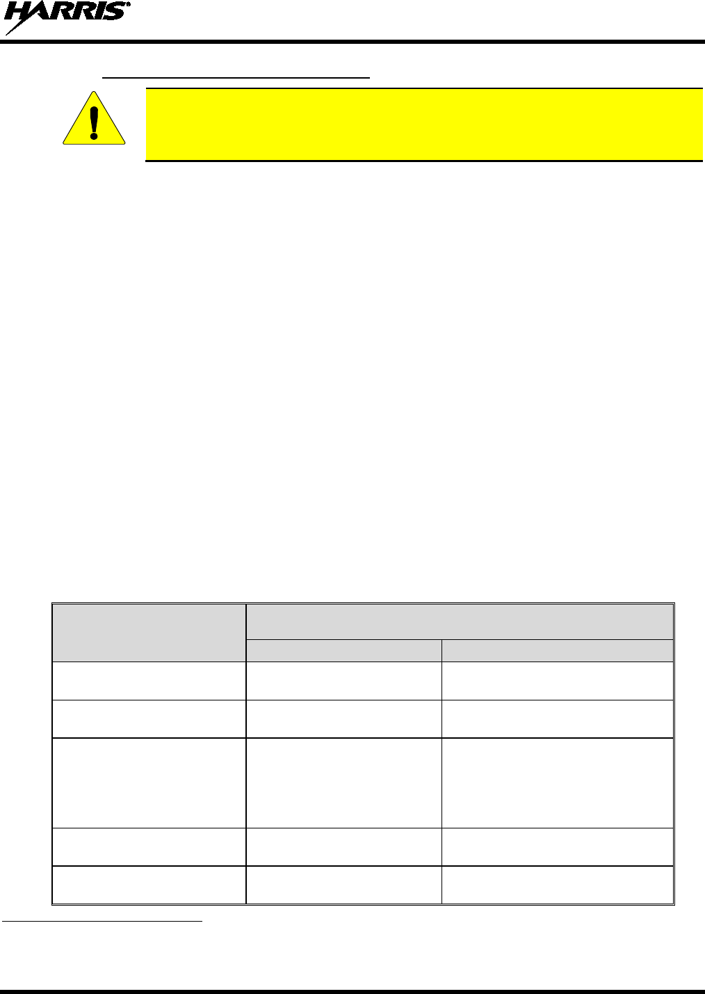
Tableau 2-1 : Distances de test de conformité des expositions aux RF
RADIOFRÉQUENCES
DISTANCES TESTÉES
(pire des scénarios)
Corps3 Visage
VHF
(136 - 174 MHz) 1,2 cm 2,5 cm
UHF
(378 - 522 MHz) 1,2 cm 2,5 cm
700/800 MHz
(768 - 776 MHz)
(798 - 806 MHz)
(806 - 824 MHz)
(851 - 870 MHz)
1,2 cm 2,5 cm
2400 MHz
(2412 - 2472 MHz) 1,2 cm 2,5 cm
5 GHz
(5.18 - 5.825 GHz) 1,2 cm 2,5 cm
3 Ce est le pire des cas basée sur le corps plus mince monter accessoire (clip ceinture).

14221-1800-2000, Rev. D
16
Dans cette section figurent les renseignements nécessaires pour sensibiliser l’utilisateur à l’exposition aux
RF et sur ce qu’il faut faire pour s’assurer que cette radio fonctionne dans les limites d’exposition aux RF
de la FCC.
2.2.2 Interférence/Compatibilité Électromagnétique
Pendant les transmissions, cette radio Harris produit de l’énergie des RF qui peut causer de l’interférence
avec d’autres appareils ou systèmes. Pour éviter de telles interférences, fermez la radio dans les zones où
il est indiqué de le faire. N’utilisez PAS le transmetteur dans des zones sensibles aux radiations
électromagnétiques, comme les hôpitaux, les avions et les sites de détonation.
2.3 INTERFÉRENCE DES RADIOFRÉQUENCES
2.3.1 Partie 15 de la FCC
Cet appareil est conforme à la Partie 15 de la réglementation de la FCC. Le fonctionnement est soumis
aux deux conditions suivantes :
1. Cet appareil ne doit pas causer une interférence nuisible; et
2. Cet appareil doit accepter toute interférence reçue, y compris une interférence qui peut causer un
fonctionnement non souhaité.
2.3.2 Industrie Canada
Le présent appareil est conforme aux CNR d'Industrie Canada applicables aux appareils radio exempts de
licence. L'exploitation est autorisée aux deux conditions suivantes : (1) l'appareil ne doit pas produire de
brouillage, et (2) l'utilisateur de l'appareil doit accepter tout brouillage radioélectrique subi, même si le
brouillage est susceptible d'en compromettre le fonctionnement.
2.4 CONSEILS D’UTILISATION
L’emplacement et l’état de l’antenne sont importants pour l’utilisation d’une radio portative. L’utilisation
de la radio dans des zones de faible élévation, sous des lignes électriques ou des ponts, à l’intérieur d’un
véhicule ou dans un immeuble à ossature métallique, peut réduire la portée de l’appareil de manière
considérable. Les montagnes peuvent également réduire la portée de l’unité.
Dans les zones où la transmission ou la réception est insatisfaisante, certaines améliorations peuvent être
obtenues en s’assurant que l’antenne est verticale. Se déplacer de quelques mètres dans une autre
direction ou à un emplacement plus élevé peut également améliorer les communications. L’utilisation
d’une antenne fixée à l’extérieur peut faciliter le fonctionnement dans un véhicule.
L’état de la pile est un autre facteur important d’une utilisation sans tracas d’une radio portative. Chargez
toujours correctement la pile.
2.4.1 Utilisation Efficace de la Radio
Gardez l’antenne dans une position verticale pendant la réception ou la transmission d’un message.
MISE EN GARDE
Ne tenez PAS l’antenne lorsque la radio est allumée!
14221-1800-2000, Rev. D
17
2.4.1.1 Entretien Et Remplacement De L’antenne
MISE EN GARDE
N’utilisez pas la radio portative si son antenne est endomm
agée ou absente. Une
brûlure légère peut se produire au contact d’une antenne endommagée avec la
peau. Remplacez immédiatement une antenne endommagée. L’utilisation d’une
radio portative alors que l’antenne est absente peut causer des blessures,
endommager la radio et pourrait enfreindre la réglementation de la FCC.
AVERTISSEMENT
Utilisez seulement l’antenne fournie ou une antenne approuvée. Des antennes non
autorisées, des modifications ou des ajouts à une antenne peuvent endommager la radio et
enfreindre la réglementation de la FCC. (Reportez-vous à Table 4-1.)
2.4.1.2 Appareils Électroniques
AVERTISSEMENT
L’énergie des RF provenant de radios portatives peut affecter certains appareils
électroniques. La ma
jorité de l’équipement électronique moderne dans les voitures, les
hôpitaux, les maisons, etc. est blindé contre l’énergie des RF. Cependant, dans les zones
où l’on vous demande de fermer l’équipement de radio bidirectionnelle, respectez toujours
les règles. En cas de doute, éteignez-le!
2.4.1.3 Avion
MISE EN GARDE
• Éteignez toujours une radio portative avant d’embarquer à bord d’un avion!
• Ne l’utilisez au sol qu’avec la permission de l’équipage.
• NE l’utilisez PAS durant le vol!
2.4.1.4 Détonateurs Électriques
MISE EN GARDE
Pour prévenir la détonation accidentelle des détonateurs électriques, n’utilisez PAS
de radios bidirectionnelles à moins de 305 m (1 000 pi) des opérations de détonation.
Respectez toujours les indications « Éteindre les radios bidirectionnelles » situées là
où des détonateurs électriques sont utilisés. (Norme OSHA : 1926.900)

14221-1800-2000, Rev. D
18
2.4.1.5 Atmosphère Potentiellement Explosive
MISE EN GARDE
Les zones ayant une atmosphère potentiellement explosive sont souvent, mais pas
toujours, identifiées clairement comme telles. Il peut s’agir de zones d’alimentation
en carburant, comme les postes d’essence, les installations de stockage ou de
transfert de carburant ou de produits chimiques, ainsi que les zones dont l’air
contient des produits chimiques ou des particules, comme des grains, de la poussière
ou des poudres métalliques.
Des étincelles dans de telles zones peuvent provoquer une explosion ou un incendie,
causant ainsi des blessures ou même la mort.
Éteignez les radios bidirect
ionnelles dans toute zone ayant une atmosphère
potentiellement explosive. Il est rare, mais pas impossible qu’une radio ou ses
accessoires produisent des étincelles.
14221-1800-2000, Rev. D
19
3. HAZARDOUS LOCATIONS
(APPLIED FOR CERTIFICATION)
This equipment is suitable for use in Class I, Division 2, Groups A, B, C, and D or non-hazardous
(unclassified) locations only.
Cet équipement convient pour usage en Classe I, Division 2, Groupes A, B, C et D, ou en sites non-
hasardeux (non-classifiés) seulement
EXPLOSION HAZARD – REPLACE BATTERY PACK ONLY IN AN AREA
KNOWN TO BE NON-
HAZARDOUS, AND ONLY WITH HARRIS PART NO.
14035-4010-01.
AVERTISSEMENT – RISQUE D’EXPLOSION –
LES BATTERIES DOIVENT
ÊTRE REMPLACÉES DANS UNE ZONE RECONNUE NON-HASARDEUSE
SEULEMENT, ET SEULEMENT AVEC UNE BATTERIE H
ARRIS PORTANT
LE NUMÉRO DE PIÈCE 14035-4010-01.
EXPLOSION HAZARD – Substitution of any component may impair suitability for
Class I, Division 2.
AVERTISSEMENT – RISQUE D’EXPLOSION –
Une substitution de toute
composante pourrait compromettre la convenance pour la Classe I, Division 2.
EXPLOSION HAZARD –
Do not exceed maximum battery charging current of
5.250 A or maximum charging voltage of 12.0 V DC at any time.
CAUTION - The battery used in this device may present a risk of fire or explosion
w
hen heated above 100°C (212°F) or incinerated. Replace battery with Harris Part
No. 14035-4010-
01 only. Use of another battery may present a risk of fire or
explosion.
Battery replacement instructions: Remove battery by 1) depressing battery latches then 2) remove battery
from radio chassis. Install replacement battery by inserting battery in radio chassis opening and
depressing battery into chassis until both battery latches are engaged. Dispose of used battery promptly.
Keep away from children. Do not disassemble and do not dispose of in fire.
EXPLOSION HAZARD – In addition to any simple single-ended coil antenna, only
the following Harris accessories may be used with this radio:
PART NUMBER
DESCRIPTION
12082-0600-01
SPEAKER MICROPHONE
12082-0600-02
Speaker Microphone, Emergency Button
12082-0650-01
Microphone,Palm,2 Wire, Black
12082-0650-02
Microphone,Palm,2 Wire, Beige
12082-0650-03
Microphone,Mini-Lapel,3 Wire, Black
12082-0650-04
Microphone,Mini-Lapel,3 Wire, Beige
12082-0650-05
EARPHONE KIT,BLACK,XG-100P
12082-0650-06
EARPHONE KIT,BEIGE,XG-100P
WARNING
WARNING
WARNING
WARNING
WARNING

14221-1800-2000, Rev. D
20
PART NUMBER
DESCRIPTION
12082-0650-07
Headset, In-Ear, Boom Mic, In-Line PTT
12082-0650-08
Headset, Lightweight, Over-the-Head, Single Ear, In-Line PTT
12082-0650-09
Headset, Lightweight, Behind-the-Head, Dual Ear, In-Line PTT
12082-0650-10
Headset, Lightweight, Behind-the-Head, Dual Ear, Pigtail PTT
12082-0650-13
Headset, Heavy Duty, Behind-the-Head, w/PTT
12082-0650-14
Headset, Heavy Duty, Over-the-Head, w/PTT
12082-0650-15
Headset, Behind-the-Head, Boom Mic, Earpiece, w/PTT
12082-0650-16
Headset, Tactical, Boom Mic, Earpiece, w/PTT
12082-0650-17
Skull Mic, w/Body PTT and Earcup
12082-0650-18
Throat Mic, W/Acoustic Tube & Body PTT
12082-0650-19
Throat Mic, w/Acoustic Tube, Body and Ring PTT
LS103239V1
Earphone, Lapel Microphone, 2.5mm
LS103239V2
Earphone, Lapel Microphone, 2.5mm, RT Angle
12150-1000-01
Speaker Mic, Premium, Fire (FSM), Noise Cancelling

14221-1800-2000, Rev. D
21
4. INTRODUCTION
4.1 DESCRIPTION
The XL-200P provides the advanced connectivity that first responders require while addressing evolving
voice and data communications. It supports VHF, UHF, and 700/800 MHz, allowing voice and data
communications across agencies using multiple frequencies and systems. The XL-200P delivers easy-to-
use tools in an extremely rugged radio that operates under the most adverse conditions. The XL-200P
meets MIL-STD-810G for durability and is certified to more stringent MIL-STD parameters for
contamination by fluids and explosive atmospheres. The XL-200P is available in both Full and Partial
keypad models in black and high-visibility yellow.
Standard features found on the XL-200P include:
• Extremely Rugged – exceeds the standards of other radios on the market.
• Multiband Operation – supports any combination of VHF, UHF, and 700/800 MHz frequencies. Also
allows different bands to be enabled for selected users.
• Single-key DES Encryption – provides basic secure communications without having to buy the
complete encryption option.
• Instant Recall of Received Audio – allows user to replay the last transmission received to avoid
unnecessary repetition.
• Active Noise Cancellation – with three internal microphones to transmit intelligible audio from users
in loud environments.
• Built-in GPS – for location reporting and rapid response for emergencies.
• Integrated Bluetooth® – for wireless interface to selected accessories.
• Wi-Fi® Connectivity – permits simple and easy radio software and personality updates.
• Covert Mode – allows users to quickly configure the radio for operation in a covert environment.
• Fully Programmable Keypad – each key can be programmed to a variety of functions.
• 4 position switch – provides added configuration flexibility.
• Unique User Interface – tools specially designed by first responders make radio operation simple and
intuitive. An easy-to-read multi-color front display and a monochromatic top display with optional
colored backlighting enhance communications for improved user safety.
For optional accessories, refer to Table 4-1. Additional accessories may have been added since
publication of this manual; contact Harris for more information.
4.2 STORAGE GUIDELINES
Store your XL-200P and batteries in a clean, cool (not exceeding 86 °F [+30 °C]), dry, and ventilated
storage area.
14221-1800-2000, Rev. D
22
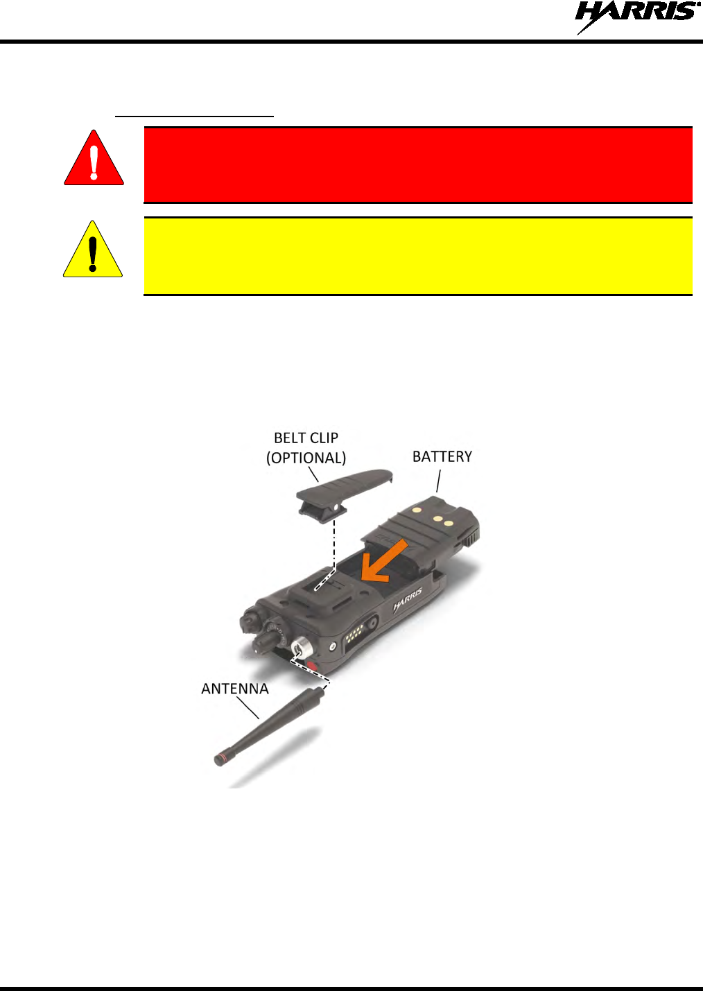
4.3 BASIC SETUP
4.3.1 Assemble the Radio
Only use a Harris charger approved for the battery chemistry. Injury could occur
from improper charger use.
Do not over-tighten the antenna as damage could result.
1. Make sure batteries are charged per the manual supplied with the charger.
2. To attach optional belt clip, remove the existing tab from the back of the radio above the battery
compartment. Slide the belt clip into the groove.
3. Lift clip, if installed, and slide top of battery into top of battery compartment at the rear of the radio.
4. Press down on bottom side of battery until it snaps into place.
Figure 4-1: Radio Assembly
WARNING
CAUTION
14221-1800-2000, Rev. D
23
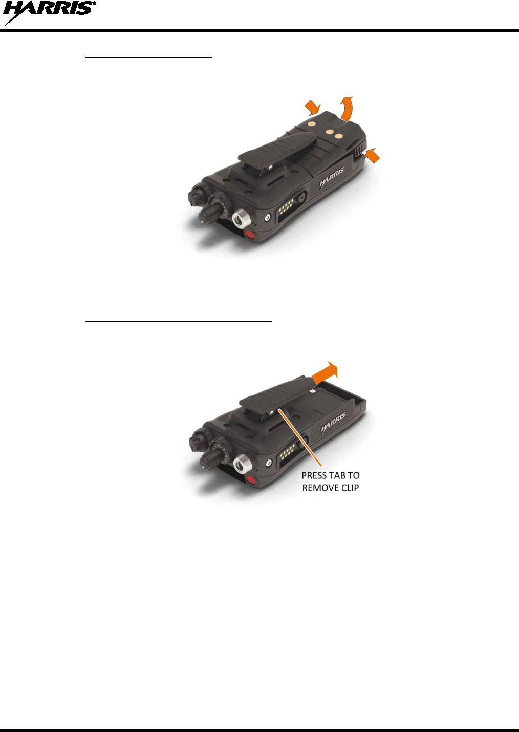
4.3.2 Removing the Battery
To remove, press and hold the two tabs at the bottom of the battery and then pull battery up and out of the
radio.
Figure 4-2: Remove the Battery
4.3.3 Removing the Optional Belt Clip
Remove the battery before removing the belt clip. To remove the belt clip, press and hold the tab towards
the top of the battery compartment and slide the belt clip out of the groove in the back of the radio.
Figure 4-3: Remove Belt Clip
14221-1800-2000, Rev. D
24
4.4 UNIVERSAL DEVICE CONNECTOR
The Universal Device Connector (UDC) provides connections for external accessories such as a headset,
a speaker-microphone, audio test box, audio test cables, and programming cables. The UDC is located on
the right side of the radio, opposite the PTT Button. The UDC facilitates programming and testing the
radio. The UDC pins perform different functions depending on the accessory attached to the UDC.
Figure 4-4: Universal Device Connector
4.5 CLEANING
Keep the exterior of the radio, battery, antenna, and radio accessories clean.
Periodically clean using the following procedures:
1. To remove dust and dirt, clean using damp clean cloth (warm water and mild detergent soap).
2. Follow by wiping with damp (warm water) clean cloth. Wipe dry with clean cloth.
3. Remove the battery and wipe the battery and radio contacts using a soft dry cloth to remove dirt or
grease. This will ensure efficient power transfer from the battery to the radio.
4. Remove any accessories and clean the UDC contacts using a clean dry cloth. When the UDC is not
in use, cover the connector with the protective dust cap to prevent the build-up of dust or water
particles.
5. If the radio is used in a harsh environment (such as driving rain, salt fog, etc.), it may be necessary to
periodically dry and clean the battery and radio contacts with a soft dry cloth or soft-bristle non-
metallic brush.

14221-1800-2000, Rev. D
25
For more rigorous cleaning, use the following procedure:
CAUTION
Do not use chemical cleaners, spray, or petroleum-based products. They may damage
the radio housing. We recommend using Chemtronics® Electro-Wash® PR (ES-1603) or
equivalent.
1. Apply the cleaning solution to a clean damp cloth and clean the radio.
Do not spray cleaning solution directly on radio. To clean the radio in the speaker and
microphone areas, carefully wipe these areas but prevent the cleaning solution from
entering the speaker or microphone openings.
2. Wipe off the radio with clean damp cloth using mild warm soapy water.
3. Follow up by wiping off the radio with clean damp cloth using warm water only.
4. Wipe dry with clean cloth.
NOTE
14221-1800-2000, Rev. D
26
4.6 OPTIONS AND ACCESSORIES
Only use Harris approved accessories. Refer to Harris’ Product and Services catalog for the complete list
of options and accessories available. Contact Harris for requirements not contained in this list:
Always use the correct options and accessories (battery, antenna, speaker/mic, etc.) for
the radio. Immersion rated options must be used with an immersion rated radio. Refer to
Table 4-1.
Table 4-1: Options and Accessories
DESCRIPTION
PART NUMBER
OPTION NUMBER
ANTENNAS
Antenna, Full Spectrum
14035-4000-01
XL-NC5Z
Antenna, Whip Wideband 378-520 MHz, 762-870 MHz
14035-4420-01
XL-NC8E
Antenna, Whip, 1/4 Wave, 762-870 MHz,
14035-4440-02
XL-NC8F
Antenna, Whip, 1/2 Wave, 762-870 MHz
14035-4440-01
XL-NC8D
BATTERIES/CHARGERS
Battery, Lithium, Standard Capacity
14035-4010-01
XL-PA3V
Charger, Single Bay
14035-1800-01
XL-CH4X
Charger, Multi Bay
14035-1800-02
XL-CH5A
Charger, Vehicular
14035-4100-01
XL-CH4W
AUDIO ACCESSORIES
Speaker Microphone
12082-0600-01
XL-AE9N
Speaker Microphone, Emergency Button
12082-0600-02
XL-AE4B
Speaker Microphone, Wireless, Bluetooth
12082-0681-01
XL-AE6K
Speaker Microphone, Premium, Fire, Noise Cancelling
12150-1000-01
XL-AE1T
Speaker Microphone, Premium, Fire, Noise Cancelling,
High Visibility Yellow
12150-1000-05
Microphone, Palm, 2-Wire, Black
12082-0650-01
XL-AE6G
Microphone, Palm, 2-Wire, Beige
12082-0650-02
XL-AE6M
Microphone, Mini-Lapel, 3-Wire, Black
12082-0650-03
XL-AE6H
Microphone, Mini-Lapel, 3-Wire, Beige
12082-0650-04
XL-AE6N
Earphone Kit, Black
12082-0650-05
Earphone Kit, Beige
12082-0650-06
Headset, In-Ear, Boom Mic, In-Line PTT
12082-0650-07
XL-AE2A
Headset, Light Weight, Over-the-Head, Single Ear, In-
Line PTT
12082-0650-08 XL-AE2B
Headset, Light Weight, Behind-the-Head, Dual Ear, In-
Line PTT
12082-0650-09 XL-AE2C
Headset, Light Weight, Behind-the-Head, Dual Ear, Pig
Tail PTT
12082-0650-10 XL-AE2D
Headset, Light Weight, Behind-the-Head, Dual In-Ear,
In-Line PTT
12082-0650-11 XL-AE2E
Headset, Light Weight, Behind-the-Head, Dual In-Ear,
Pig Tail PTT
12082-0650-12 XL-AE2F
Headset, Heavy Duty, Behind-the-Head, w/PTT
12082-0650-13
XL-AE1P
Headset, Heavy Duty, Over-the-Head, w/PTT
12082-0650-14
XL-AE1R
Headset, BTH Boom Mic, Earpiece, w/PTT
12082-0650-15
XL-AE2G
Headset, Tactical, Boom Mic, Earpiece, w/PTT
12082-0650-16
XL-AE1H
Skull Mic, w/Body PTT, Earcup
12082-0650-17
XL-AE1L
Throat Mic, w/Acoustic Tube, Body PTT
12082-0650-18
XL-AE1M
Throat Mic, w/Acoustic Tube, body and Ring PTT
12082-0650-19
XL-AE1N
Bluetooth, Covert, Earpiece/MIC/PTT, Radios
12082-0684-01
XL-AE1S
MISCELLANEOUS ACCESSORIES
Cable, Data Interface
12082-0445-A1
XL-CJ4A
Cable, MATQ-03424, Test
12082-0435-A1
CAUTION

14221-1800-2000, Rev. D
27
DESCRIPTION
PART NUMBER
OPTION NUMBER
Cable, USB, Key Loading/Programming
12082-0410-A1
XL-CJ3A
Cable, KVL, Key Loading
12082-0400-A1
XL-CJ3B
Adapter, 6-Pin Hirose
14002-0197-01
XL-CJ4B
Holster, Leather, Radio, Premium
14035-4201-01
XL-HC4K
Belt Loop, Leather, Premium
14002-0218-01
XL-HC4A
D-Swivel
12082-3230-01
Strap, Shoulder
CC103333V1
Metal Belt Clip
12082-1290-01
XL-HC3L
Case, Leather, Premium, Shoulder Strap
14035-4201-02
XL-HC4L
14221-1800-2000, Rev. D
28
5. BASIC OPERATION
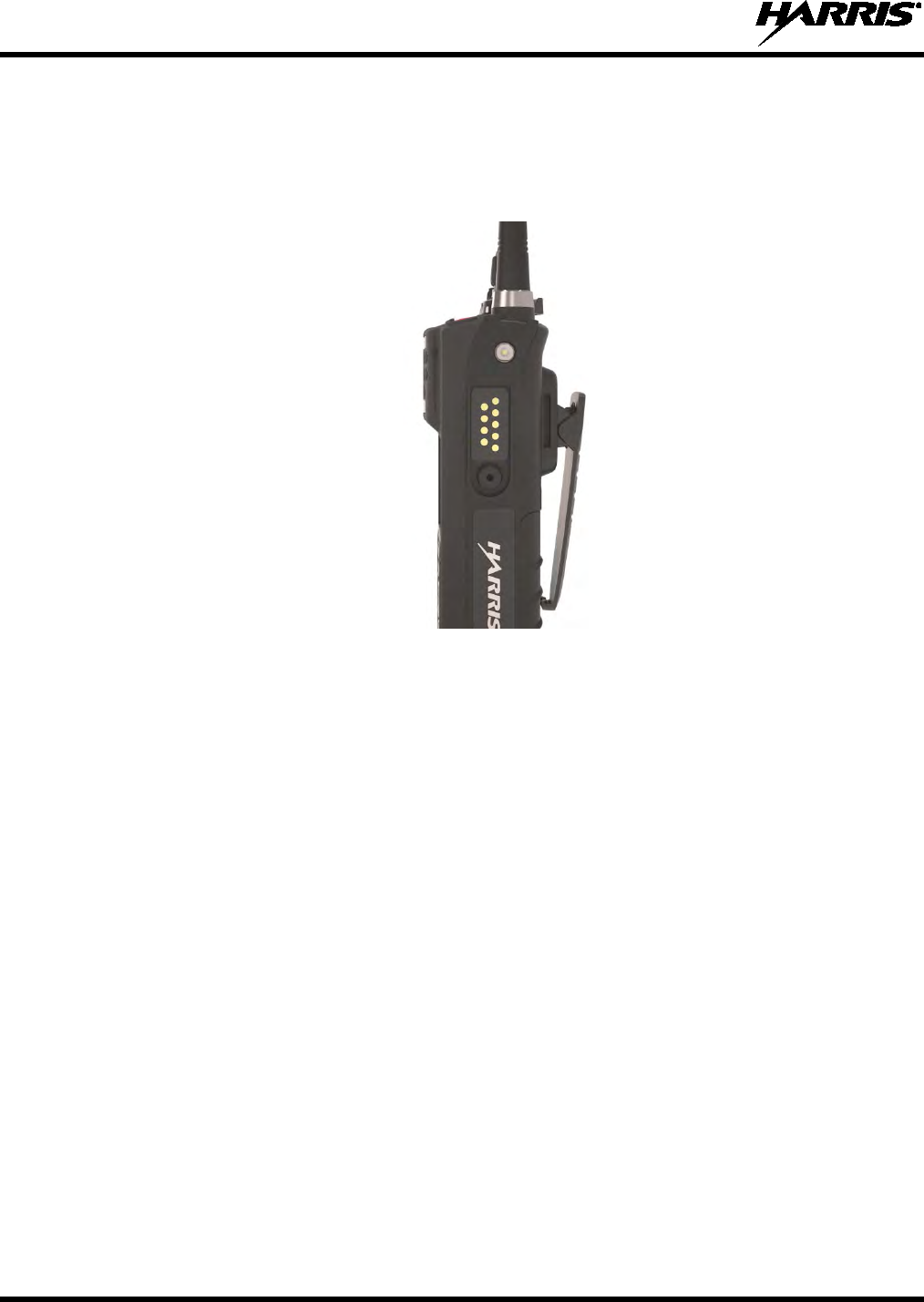
5.1 XL-200P CONTROLS
Figure 5-1: XL-200P Controls
Table 5-1 describes the default functions of buttons, knobs, and controls. Most can be
programmed for different functions; see Section 7.4 for more information.
Table 5-1: XL-200P Controls, Indicators, and Connectors
CONTROL/INDICATOR
FUNCTION
Group/Channel Knob
Selects groups/channels.
Power/Volume Knob
Turn clockwise to power on radio and increase volume of audio heard from
speaker. Minimum volume levels may be programmed into the radio to prevent
missed calls due to a low volume setting.
A/B (Ø/O) Switch
User-programmable switch (see Section 7.4.2).
NOTE

14221-1800-2000, Rev. D
29
CONTROL/INDICATOR
FUNCTION
Microphone
(Secondary)
When noise cancellation is enabled, the secondary and primary microphones are
used together to form a dual microphone system. Noise cancellation improves the
quality of transmitted voice. When noise cancellation is disabled, only the primary
microphone is used. See Section 5.7
for detailed information on using noise
cancellation.
A/B/C/D Switch
User-programmable switch (see Section 7.4.3). By default, selects one of four
channel banks (see Section 5.17).
User-Programmable
Buttons
Used to select a commonly used function as an alternative to navigating menus.
This is configured via programming using Radio Personality Manager 2 (RPM2).
See Section 7.4.1 for the options that can be programmed to these buttons.
Push-To-Talk (PTT)
Button
Press to transmit. Make sure Push-To-Talk (PTT) is enabled (Section 6.5).
Battery
Battery - Refer to Section 4.3 for battery connection and removal.
Antenna Connector
Antenna connector.
Emergency Button
Used to place radio in emergency mode (see Section 5.31). This button can be
disabled via programming using RPM2. In addition, this button can be used in
conjunction with a User Programmable Button to Clear Emergencies if configured
to do so.
Indicator Light Emitting
Diode (LED)
Indicates radio status:
• Red = actively transmitting.
• Green = actively receiving.
• Orange = actively transmitting encrypted.
Top Display
Shows summary of radio operation, including channel/talkgroup (which can be
color coded), as well as a variety of programmable icons. Display orientation can
be configured for viewing from the front or rear of the radio. (Section 6.6).
Speaker
Radio speaker which can be muted (Section 6.5). Adjust volume using the
Power/Volume knob.
Microphones (Primary)
When noise cancellation is enabled, the primary and secondary microphones are
used together to form a dual microphone system. Noise cancellation improves the
quality of transmitted voice. When noise cancellation is disabled, only the primary
microphones are used. See Section 5.7 for detailed information on using noise
cancellation.
Front Display
Front display shows complete status and radio menus.
User-Programmable
Soft Keys
User-programmable dynamic keys that have their current function labeled on the
radio display directly above each button. See Section 7.4.1 for the options that
can be programmed to these buttons.
Menu/Select Button
From the Main Display, press this button to access the menu. Also selects
highlighted menu items.
14221-1800-2000, Rev. D
30
CONTROL/INDICATOR
FUNCTION
Navigation Buttons
Navigates menu items.
In addition:
Press
while on the idle display to access Channel Information (see Section
6.4).
Press while on the idle
display to display the functions assigned to
programmable buttons (see Section 7.4).
Press to display Missed Call info.
Press to end or reject an ICALL.
Keypad
By default, used to enter text or numbers. Can be programmed for various
functions (see Section 7.4).
The partial keypad model of the XL-2
00P supports a “soft”
DTMF keypad. This allows the radio user to utilize a graphical
DTMF keypad in place of a physical DTMF keypad.
5.2 SOFT DTMF KEYPAD
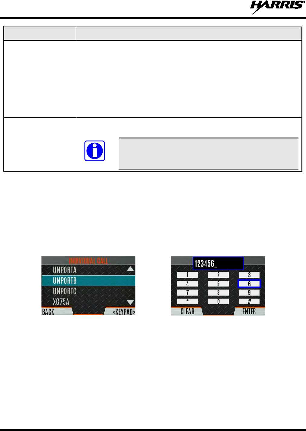
The partial keypad model of the XL-200P supports a “soft” DTMF keypad. This allows the radio user to
utilize a graphical DTMF keypad in place of a physical DTMF keypad.
On screens that require keypad entry, press the KEYPAD softkey to display the keypad. Use , , ,
and to navigate, press the Menu/Select button to select highlighted digit, and then press the ENTER
softkey.
For example, when placing an Individual Call to a numeric address, the soft DTMF keypad can be used to
enter the address as shown:
Figure 5-2: Using the Soft DTMF Keypad
5.3 BEFORE FIRST USE
Make sure XL-200P has:
• Fully charged battery
• Antenna attached
• Personality and radio programmed using RPM2
• Encryption keys loaded if using encrypted channels
• Personality activated
NOTE
14221-1800-2000, Rev. D
31
5.4 POWER ON AND SET VOLUME
The power switch and volume control are the same knob on top of the radio (see Figure 5-1). Turn the
Power/Volume Knob clockwise to power on XL-200P and increase the volume.
A minimum volume level can be programmed into the radio to prevent missed calls due
to a low volume setting.
The radio can be programmed to require the entry of a PIN in order to operate the radio.
Check with your System Administrator if you forget your PIN. As the PIN is entered, an
asterisk is displayed for each digit; the actual value is not displayed.
5.5 RADIO DISPLAYS
5.5.1 Top Display
The top display (Figure 5-3) shows a summary of status, such as channel number/bank, channel short
name, battery, scanning, and emergency mode. The display can be configured for viewing from the front
or rear of the radio (see Section 6.6). The channel short name is programmed in RPM2.
Figure 5-3: Top Display
5.5.2 Front Display
Figure 5-4 shows a sample front display while on the idle screen. The idle screen appears after power up
or after exiting from the menus.
Figure 5-4: Sample Idle Front Display
NOTE
NOTE
14221-1800-2000, Rev. D
32
Table 5-2 describes some of the icons that may be displayed by the XL-200P. The radio menu also
contains an icon glossary in the Utility Menu (see Section 5.7). Icons and their location can be
customized using RPM2.
Table 5-2: Radio Icons
ICON
DESCRIPTION
ICON
DESCRIPTION
ICON
DESCRIPTION
(Blue)
Trunked Signal Strength
Bluetooth Enabled
Monitor On
(Red)
TX Power
(Blue)
Bluetooth Connected
VDOC
(Green)
Receive Signal Strength
Encryption Enabled
Receiving Data
(No Color)
Channel Idle
Global Encryption
Transmitting Data
(Orange)
Transmitting Encrypted
OTAR Disabled
Alert(s) Present
Battery Fully Charged
OTAR Registered
Vote Scanning
Battery Level
100% Capacity
OTAR Registering
Scanning Enabled
Battery Level
75% Capacity
OTAR Rekeying
Emergency
Battery Level
50% Capacity
Transmit Power Level High
RX Mail
Battery Level
25% Capacity Transmit Power Level Low
Noise Cancellation Enabled
Fire Speaker Mic Attached
Battery Level
5% Capacity
(Low Battery Audio Indicator)
RX Only Nuisance Channel
Battery Level
Battery Exhausted
(RX-Only State)
Speaker Muted
Conventional Site
Unregistered
Battery Charging TX Disabled
Conventional Site
Registered
Talkaround Enabled
Tones Disabled Type 99 Enabled
Failsoft
PTT Disabled
GPS Tracking
14221-1800-2000, Rev. D
33
5.6 STATUS MESSAGES
The radio may display various radio Status Messages during operation. These messages are described in
Table 5-3. Table 5-3: Status Messages
MESSAGE
DESCRIPTION
PTT DENIED P25 Trunked only - The radio or talkgroup is not authorized to operate on the selected
system and/or talkgroup.
CALL QUEUED P25 Trunked only - The system has placed the call in a request queue.
SYSTEM BUSY P25 Trunked only - The system is busy, no channels are currently available, the queue is
full, or an individual call is being attempted to a radio that is currently transmitting.
SCANNING The radio is scanning.
TX EMERGENCY An emergency call is being transmitted.
RX EMERGENCY An emergency call is being received. The radio displays the unit name or unit ID.
WIDE AREA SCAN P25 Trunked only - The radio has entered the Wide Area Scan mode to search for a new
system.
INVALID TALKGROUP P25 Trunked only - The current talkgroup is not valid for the current system. This could
happen if the site denies registration due to an unrecognized talkgroup ID.
INVALID UNIT P25 Trunked only - The current unit is not valid for the current system.
REGISTERING P25 Trunked only - Displayed when the radio is performing a registration/affiliation on a
P25 trunking site.
CTRL CHANNEL SCAN P25 Trunked only - The control channel is lost and the radio has entered the Control
Channel Scan mode to search for the control channel (usually out of range indication).
BAND SCANNING
P25 Trunked only - Only displayed if the P25T system is configured for "EnhancedCC"
mode of operation. When the radio cannot find a Control Channel in either the trunked
frequency set or the list of discovered adjacencies, the radio is able to perform a full
spectrum frequency scan to find a new Control Channel.
MISSED CALL P25 Modes Only – Another user has tried to call or page this radio. The user can view
who the caller was by pressing the key.
OTAR REKEY
COMPLETE OTAR Rekey operation completed successfully.
5.7 MENU
Press the Menu/Select button while on the idle display to access the menu. Press the or buttons to
navigate the top-level menus, and press the or buttons to navigate the sub-menus. Refer to Figure
5-1 for button location. While in a menu, press the Menu/Select button to choose, activate, or toggle the
selected item; similar to an enter key. Table 5-4 provides a high-level overview of the menu layout.
Menu options on your radio may vary depending on available features and radio programming.
Table 5-4: Menu Navigation
TOP-LEVEL
MENUS
SUB-MENUS DESCRIPTION
CALL
EXIT EMERGENCY Exits emergency. See Section 5.31 for more information.
TALKAROUND MODE Enable/disable talk-around. See Section 5.22 for more information.
TYPE 99 TOGGLE Enable/disable T99. See Section 5.23 for more information.
TONE ENCODE Analog conventional only - Transmits a programmed tone sequence on the current radio
system and channel. See Section 6.19 for more information.

14221-1800-2000, Rev. D
34
TOP-LEVEL
MENUS
SUB-MENUS DESCRIPTION
CALL
(Continued)
INDIVIDUAL CALL Allows you to select an individual for an individual call. See Section 5.14 for more
information.
CHANGE TLKGRP Change the selected talkgroup. See Section 5.13.
CALL ALERT Select a group for Call Alert transmission. See Section 5.24.
CHANNEL GUARD Select the Transmit and/or Receive Channel Guard tone. See Section 5.21.
AUDIO PLAYBACK Replays the last recorded call. See Section 5.26 for more information.
SCAN
START SCAN/STOP SCAN Start or stop scan operation. See Sections 5.27 and 5.28.
SCAN LISTS View/Edit available scan lists. See Section 6.14.
ASSIGNED CUSTOM LIST Create, View, and Edit Custom Scan Lists. See Section 6.14.6.
SITE ROAMING Enable/Disable Wide Area System Scan. See Section 6.14.7.
SECURITY
ZEROIZE KEYS Removes all encryption keys from the radio. See Section 6.20.2.
GLOBAL ENCRYPTION Enable/Disable Global Encryption. See Section 6.20.4.
GLOBAL KEY Select the Global Key. Only available if Global Encryption is Enabled. See Section
6.20.4.
ACTIVE KEYSET Select the Active Keyset. See Section 6.20.5.
KEYLIST View available key lists. See Section 6.20.6.
OTAR Enable/disable Over-the-Air Rekeying (OTAR). See Section 6.20.7.
OTAR REKEY Request that the KMF updates the keys in the radio. See Section 6.20.7.
MESSAGES
RADIO STATUS Used to send a particular status condition to the site without making a voice call. See
Section 6.15.
RADIO MESSAGE Used to send a particular message to the site without making a voice call. See Section
6.16.
TEXTLINK MESSAGES Allows the user to send a Radio TextLink message. See Section 6.17.
TEXTLINK FORMS Allows the user to send a Radio TextLink form. See Section 6.17.
TEXTLINK MAILBOX Contains received Radio TextLink messages. See Section 6.17.
FAULTS/ALERTS Displays radio faults and alerts. See Section 6.18.
UTILITY
AUDIO SETTINGS:
• SPEAKER (MUTE/UNMUTE) Mute or unmute the speaker audio.
• NOISE CANCELLATION Enable or disable Noise Cancellation. See Section 5.16.
• PTT Enable or disable Push-To-Talk (PTT). Disable PTT to prevent accidental keying, such as
when radio is in the holster or you are getting into a car.
• TONES Enable or disable radio side tones.
• KEYPAD TONES Enable or disable tones that sound when the radio’s keypad buttons are pressed.
DISPLAY SETTINGS:
• COLOR SCHEME Press the Menu/Select button to toggle the front and top display’s COLOR SCHEME for
optimum visibility in day or night conditions (NORMAL or INVERTED).
• FRONT BACKLIGHT Press the Menu/Select button to toggle the front display backlighting between
ON/OFF/MOMENTARY.
• FRONT BRIGHTNESS Press or to dim or brighten the display.
• FRONT TIMEOUT When the FRONT BACKLIGHT setting is MOMENTARY, this value specifies how long
the radio needs to be inactive before the front display’s backlight turns off. Press or
to change the time in 0.5 second increments.
• TOP BACKLIGHT Press the Menu/Select button to toggle the top display backlighting
ON/OFF/MOMENTARY.
• TOP BRIGHTNESS Press or to dim or brighten the display.
• TOP TIMEOUT When the TOP BACKLIGHT setting is MOMENTARY, this value specifies how long the
radio needs to be inactive before the top display’s backlight turns off. Press or to
change the time in 0.5 second increments.

14221-1800-2000, Rev. D
35
TOP-LEVEL
MENUS
SUB-MENUS DESCRIPTION
UTILITY
(Continued)
DISPLAY SETTINGS (Cont.)
• TOP ORIENTATION Set orientation of top display to be viewed from radio: FRONT, BACK, or AUTO. When
AUTO is selected, the radio changes the top display to be viewed from the back if an
external microphone or speaker is attached. Otherwise, the display can be viewed from
the front.
• INDICATOR LED Press the Menu/Select button to toggle the indicator LED ON or OFF.
BLUETOOTH:
• ENABLED (YES/NO) Enable/disable Bluetooth. See Section 6.10 for more information.
• PAIRING MGMT Pair Bluetooth devices with the radio. See Section 6.10 for more information.
CLOCK SETTINGS:
• TIME FORMAT Select 12 or 24 hour time display format.
• TIME ZONE Set time zone relative to Universal Time Coordinated (UTC).
GPS SETTINGS:
• GPS (ENABLED/DISABLED) Enable/disable GPS.
• POSITION INFO Displays GPS, Latitude, Longitude, and Altitude information. From this menu, click NEXT
to access SA INFO (see Section 6.2).
• ANGULAR UNITS Set unit of measurement of displayed angular units: CARDINAL, DEGREES, or MILS.
• LINEAR UNITS Set unit of measurement of displayed linear units: STATUTE, METRIC, or NAUTICAL.
• POSITION FORMAT Set format of displayed position information: Latitude/Longitude Degrees Minutes
Seconds (LAT/LONG DMS), LAT/LONG DM, Military Grid Reference System (MGRS), or
Universal Transverse Mercator (UTM).
PROGRAM:
• ACTIVATE PLAN View/Activate a personality. See Section 6.1.
• ACTIVATE PROFILE Change current profile. See Section 5.15.
MAINTENANCE
• BATTERY INFO When a smart battery is attached, displays detailed battery status information. When a
regular battery is attached, displays battery voltage.
• RADIO INFO Displays radio information, i.e., ESN, software revisions, and firmware revisions.
• TESTS Allows service personnel to run radio tests.
• PH2 LC DISPLAY For field service use only.
• DISPLAY RSSI When enabled, RSSI is displayed on the RSSI screen and in the bottom of the idle
display. -130 dBm is displayed when there is no received signal.
• TCXO TUNING For field service personnel only. Improper adjustment will result in loss of
communications.
• FEATURE INFO Displays what features are enabled on your radio.
ICON GLOSSARY Defines icons that may be displayed by the radio.
CHANGE LANGUAGE Press the Menu/Select button to toggle between available languages.
CHANGE PIN Allows you to change your PIN.
ZONE View or change zones/systems (see Sections 5.10 and 6.3.1).

14221-1800-2000, Rev. D
36
5.8 PREDEFINED MENU LAYOUTS
Depending on radio programming, some menu options described in this manual may not be available.
The XL-200P supports three predefined menu layouts: Full, Limited, and Restricted. Table 5-5 details
what is available in each layout:
Table 5-5: Predefined Menu Layouts
MENU
FULL
LIMITED
RESTRICTED
Call Menu
Exit Emergency
Talkaround
Individual Call
Change Talkgroup
Call Alert/Page
Channel Guard
Audio Playback
Tone Encode
T99
Audio Settings
Display Settings
GPS Settings
Clock Settings
Bluetooth Settings
Scan Menu
Enable/Disable Scan
View Scan List
Edit Zone Scan List
View Custom Channels
Edit Custom Scan List
Custom Scan
Site Roam
Security Menu
Encryption Enable
Zeroize
Global CKR Enable
GCKR Key Select
Active Key Set
Key List
OTAR Enable
OTAR Rekey
14221-1800-2000, Rev. D
37
MENU
FULL
LIMITED
RESTRICTED
Message Menu
Radio Status
Radio Message
Textlink Messages
Textlink Forms
Textlink Mailbox
Faults
Program Menu
Activate Plan
Activate Profile
Maintenance Menu
Radio Info
Battery
TCXO Tuning
P25 Tests
RSSI Display
Phase II Display
Feature Info
Change Language
Change PIN
Icon Glossary
Zone
5.9 ALERT TONES
The XL-200P provides audible Alert Tones or “beeps” to indicate various operating conditions. Some of
the most common tones are described in Table 5-6.
Table 5-6: Alert Tones
TONE
DESCRIPTION
SOUND/DURATION
Ready To Talk Tone
Unencrypted (Analog FM or
P25 digital)
After a PTT is pressed, this is an audible indication (tone) for
you to begin speaking into the microphone. 1000 Hz tone for 25 ms
Ready to Talk Tone
Encrypted P25 digital
After a PTT is pressed, this is an audible indication (tone) for
you to begin speaking into the microphone. 1200 Hz tone for 25 ms
PTT Denied
PTT not possible. Momentary tone is present:
• Receive only
• Key not found
• PTT button disabled
• Emergency button disabled
• Emergency not supported for current channel
• Clear transmit denied
• Trunking Channel unavailable
544 Hz tone for 75 ms
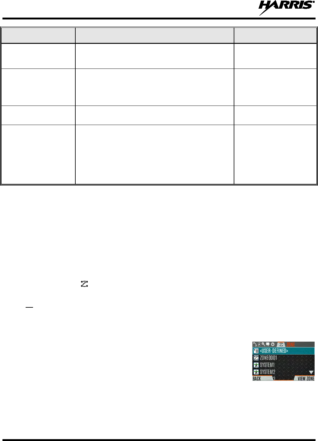
14221-1800-2000, Rev. D
38
TONE DESCRIPTION SOUND/DURATION
Maximum transmit duration
expires Maximum transmit duration is exceeded.
5 beeps of 2400 Hz tone and
then a 544 Hz tone for as long
as PTT is pressed
Low Battery Alarm
Alarm sounds upon initial detection of low battery and every
30 seconds thereafter. Tone stops upon detection of a battery
charging state.
Sequence of tones:
• 937 Hz tone for 50 ms
• Silence for 60 ms
• 1300 Hz tone for 50 ms
Emergency Call Received Radio is receiving an emergency call or priority call. 600 Hz tone for 250 ms and
1800 Hz tone for 250 ms
Out of Range Radio fails to find a local control channel.
Programmable via RPM2:
• Disabled (no tone)
• Slow (tone every 15s)
• Medium (tone every 10s)
• Fast (tone every 5s)
• Tones is 544 Hz tone for 75
ms
5.10 SELECT ZONE/SYSTEM
A System is a group of channels or talkgroups that share a common set of parameters as programmed in
RPM2. For example, a Trunking system defines the parameters needed to communicate on a particular
infrastructure by agency or geographical region, such as WACN, System ID, Talkgroups, etc. A
conventional system defines the channel set used and any specific signaling attributes (See RPM2 for
more information on System attributes). Systems are designated by the XX icon in the Zone/System
menu.
A Zone is an OPTIONAL container that can hold channels or talkgroups from a variety of systems (see
Section 6.3.2). In other words, each member of a Zone belongs to an underlying system. (See RPM2 for
more information on Zone attributes). Zones are always listed first in the Zone/System menu and are
designated by the icon. A button on the radio can be programmed to scroll through available
zones/systems (see Section 7.4).
Or
Select a zone/system via the menu:
1. Press the Menu/Select button to access the menus.
2. Use or to display the ZONE menu. The currently selected zone/system
will be highlighted. A personality can have up to 512 systems and up to 50
Zones, independent of banks or channels.
3. Use or to highlight the desired zone/system. The and buttons
may be held to scroll repetitively, and the menu will wrap to allow quick
access to a particular zone/system
4. Press the VIEW ZONE soft key to view channels in the zone/system, or
Select the desired zone/system using the Menu/Select button.
14221-1800-2000, Rev. D
39
5.11 SELECT GROUP/CHANNEL AND BANK
The XL-200P can be programmed with 1,250 talkgroups or 1000 channels per personality. Use the
Group/Channel knob to select groups/channels 1 - 16. Use the A/B/C/D switch to set the bank. The
selected bank is indicated on the display.
• Bank A: Channel A1 - A16 (1-16)
• Bank B: Channel B1 - B16 (17-32)
• Bank C: Channel C1 - C16 (33-48)
• Bank D: Channel D1 - D16 (49-64)
If your system has more than 64 groups/channels, a button on the radio can be programmed for the SEL
CHAN/GRP option. This allows you to select a “super bank,” providing access to groups/channels
beyond the first 64.
Note that ZONES have a limit of 64 entries per zone and cannot be “superbanked.”
5.12 LOCK/UNLOCK KEYPAD
There are two levels of keypad lock available. Keypad lock and Radio lock. Keypad lock only locks the
navigation keys (except for use in unlock), programmable softkeys, and DTMF keypad. Radio lock
disables all physical keys and knobs except
• The 4-position switch
• PTT
• Emergency Button
• Any User Programmable Button (UPB) programmed for Monitor/Clear (This is required to allow
Monitor/Clear to function for 2-button emergency clear)
The A/B switch, ABCD switch, or a button on the radio can be programmed to lock the keypad/radio. If
the keypad was locked via a switch, moving the switch to another position will unlock the keypad. If
locked via a button, the navigation keys must be used to enter the unlock sequence of Left, Right, Up
Down.
See Section 7.4 for the v
arious options that can be programmed to the radio buttons
and switches.
NOTE
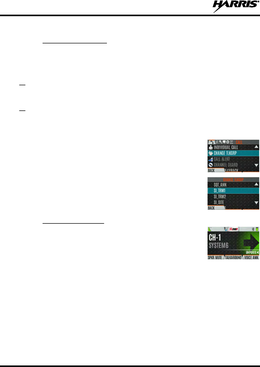
14221-1800-2000, Rev. D
40
5.13 GROUP CALLS
5.13.1 Transmit a Group Call
A talkgroup is a group of radios that you want to have private conversations with. These groups can be
divided into areas such as state, region, county, or large special events. A group call can only be made on
digital channels.
Turn the Channel/Group knob to select the desired group (see Figure 5-1). Press PTT to transmit.
Or
A button on the radio can be programmed for DIRECT CHANNEL ENTRY to allow the user to enter the
talkgroup/channel number. Press PTT to transmit.
Or
1. In P25 Conventional,
the talkgroup for the selected channel may be
overridden as follows: P
ress the Menu/Select button to access the main
menu.
2. Press or to display the CALL menu.
3. Press or to highlight CHANGE TLKGRP and press the Menu/Select
button.
4. Press or to highlight and the desired talkgroup
and press the
Menu/Select button.
After selecting the new talkgroup, the radio returns to
the main screen.
5. Press PTT to transmit.
5.13.2 Receive a Group Call
When receiving a group call, the status area of the idle display toggles between
the Unit Name and the Group Name of the transmitting radio. Note that if either
of those names is not programmed the corresponding ID number is displayed.
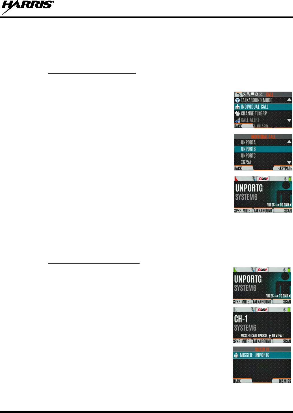
14221-1800-2000, Rev. D
41
5.14 INDIVIDUAL CALLS
An individual call is used to make a call to one radio as opposed to a group of radios. An individual call
can only be made on a digital channel.
5.14.1 Transmit an Individual Call
1. Press Menu/Select button to access the main menu.
2. Press or to display the CALL menu.
3. Press or to highlight INDIVIDUAL CALL and press the Menu/Select
button.
4. Use or
to highlight the unit to call and press the Menu/Select button,
or select KEYPAD to enter the Unit ID.
5. Press PTT to make the call.
When transmitting an Individual Call, the radio
displays the called radio’s name or Unit ID. If the radio is programmed for
Acknowledged Individual Call, the radio displays “CALL QUEUED” until
the callee answers or rejects the call.
6. After the callee answers, press PTT to respond.
7. Press to end the call.
How long the radio remains in Individual Call mode with no activity is programmable.
5.14.2 Receiving an Individual Call
1. When receiving an Individual Call, the radio display
s the calling radio’s
name or Unit ID. The radio will also display “Press to END.”
2. Press PTT to respond or to END/REJECT the call. How long the radio
remains in the Individual Call mode with no activity is programmable.
3. The radio rings and indicates a missed call if you do not respond. The ring
sounds until you press PTT, view the missed call menu (
), change
channel/group/system, or power cycle the radio.
4. On the missed call screen, press the DISMISS soft key to clear the entry.
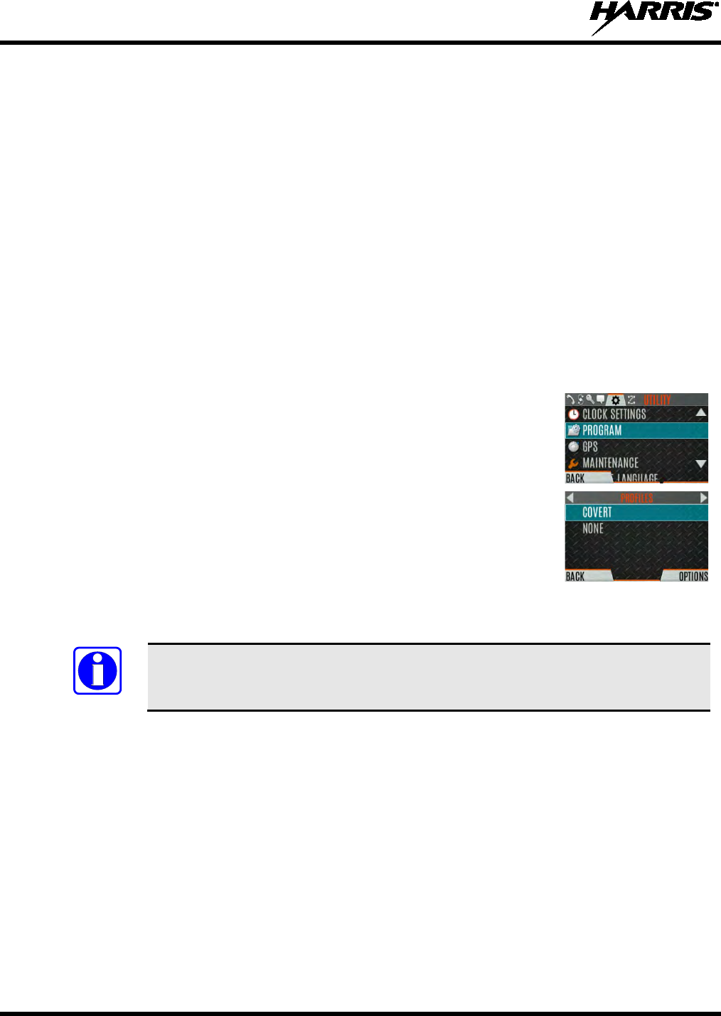
14221-1800-2000, Rev. D
42
5.15 PROFILES
The XL-200P supports a Covert profile. The following attributes apply when the Covert profile is active:
• The speaker is enabled.
• All tones are disabled.
• Keypad tones are disabled.
• Voice Annunciation is disabled.
• The front display backlight is disabled
• The top backlight is turned off.
• The indicator LED is disabled.
• All other attributes remain at their current value.
To change the currently selected Profile:
1. Press the Menu/Select button to access the menu.
2. Press or until the UTILITY menu is displayed.
3. Press or to highlight PROGRAM and press the Menu/Select button.
4. Press or until the PROFILES menu is displayed.
5. Press
or
to select the desired Profile (COVERT or NONE) and press the Menu/Select button.
A profile change persists across system/channel changes, power cycles, and personality changes.
A button on the radio keypad can be used to toggle profiles. See Section 7.4.1.
5.16 NOISE CANCELLATION
The XL-200P features Harris’ proprietary noise suppression capability to provide clear and crisp voice
quality in high-noise environments. This can be used in any mode, including analog and digital
communications.
The XL-200P has three microphones; two located at the top of the radio (primary) and one on the bottom
(secondary). When noise cancellation is enabled, voice is picked up by the upper left microphone, and
noise is picked up from the bottom microphone.
In the case where noise cancellation is enabled and a speaker microphone is attached to the XL-200P, talk
into the speaker microphone. In this mode, XL-200P top left microphone is used to pick up the
surrounding noise, and the other microphones are unused. See Section 5.16.4 for more information. If the
bottom (secondary) microphone is blocked, the XL-200P operates as though noise cancellation is turned
off.
NOTE
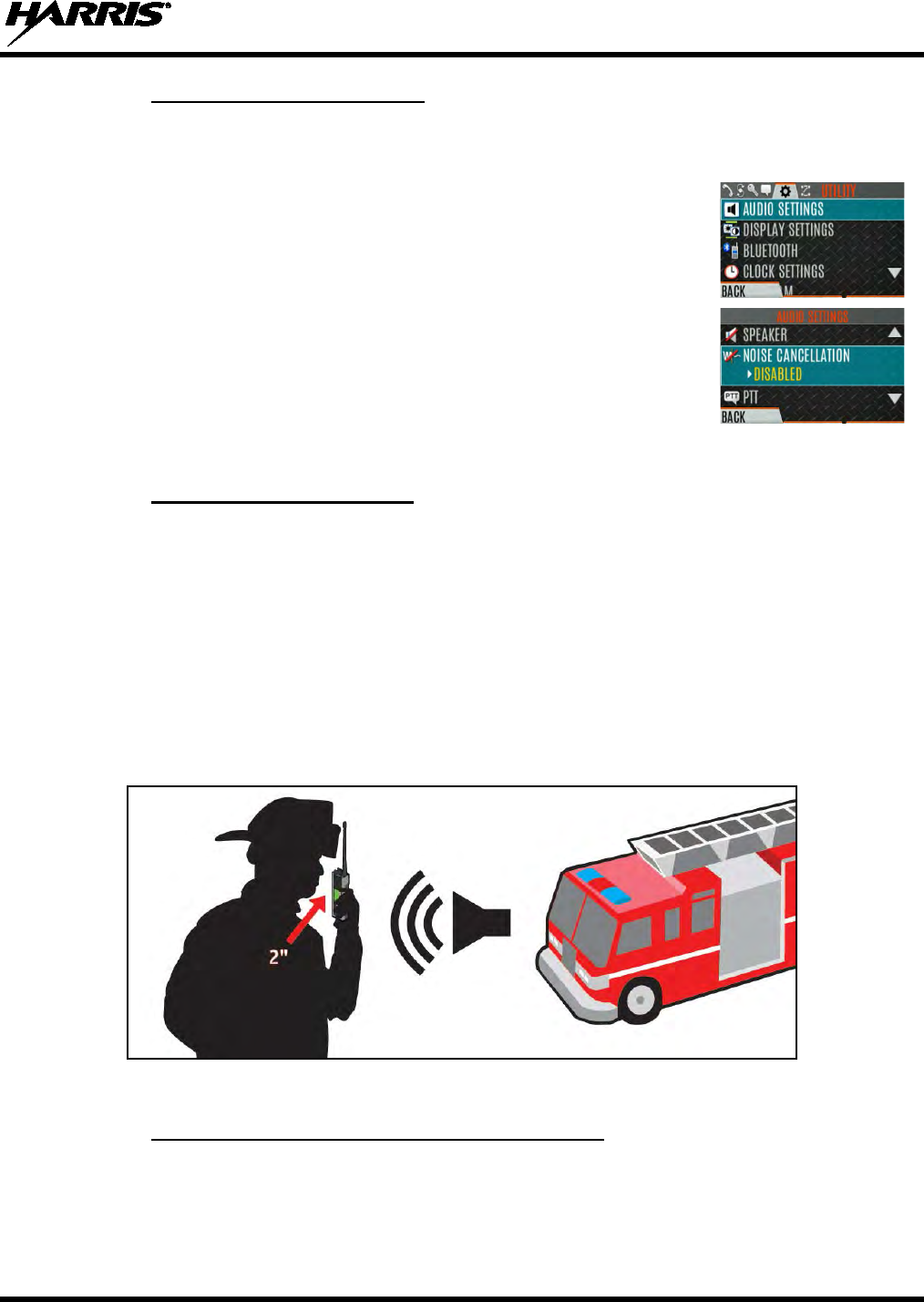
14221-1800-2000, Rev. D
43
5.16.1 Enable Noise Cancellation
To enable Noise Cancellation:
1. Press the Menu/Select button to access the menu.
2. Press or until the UTILITY menu is displayed.
3. Press or to highlight AUDIO SETTINGS
and press the
Menu/Select button.
4. Press or to highlight NOISE CANCELLATION.
Toggle Noise
Cancellation ENABLED/DISABLED using the Menu/Select button.
Refer to Section 6.5 for more information on the Audio Settings menu.
5.16.2 Using Noise Cancellation
When using the noise cancellation feature, observe the following:
• Verify NOISE CANCELLATION is enabled (see Section 5.16.1).
• Ensure the primary and secondary microphones are not covered. See Section 5.16.4 for more
information on the primary and secondary microphones.
• Talk within two (2) inches of the primary microphones (see Figure 5-5).
• Speak clearly, loudly, and with authority.
• If possible, face the noise source when talking into the radio (see Figure 5-5).
• In very noisy environments, it is o.k. to yell into the radio. The radio can handle loud input levels.
Figure 5-5: Using Noise Cancellation
5.16.3 The Effect of Distance from the Microphone
Unlike a normal microphone system, noise cancellation makes the level of your voice diminish quickly as
you move away from the radio. In essence, the radio starts to see your voice as surrounding noise.
Whereas, you may be comfortable speaking up to a foot away under normal operation, noise cancellation
requires that you hold the radio close.
14221-1800-2000, Rev. D
44
5.16.4 Primary versus Secondary Microphone
5.16.4.1 Without a Speaker Microphone Attached
The primary microphones are located on top of the radio and the secondary is on the bottom of the radio
(refer to Figure 5-1 for microphone locations).
5.16.4.2 With a Speaker Microphone Attached
When a speaker microphone is attached, the radio electronically switches over to use the radio’s top left
microphone as secondary. The microphone on the attached speaker microphone becomes primary.
5.16.5 When using an SCBA Mask
When using an SCBA mask, the primary microphone can be held directly against the voice port. If the
SCBA has a voice amplifier, the same rule applies. Ensure that the secondary microphone is uncovered. If
possible, point the secondary microphone toward the noise source.
5.17 PTT OPTIONS
The radio can be programmed via RPM2 with one of the following PTT options:
• Radio and Accessory – In this mode, when the radio is PTT’d the audio source will correspond with
the PTT source.
If the source of PTT is radio, the audio is routed via the radio microphone.
If the source of PTT is an external microphone accessory, the audio is routed via the external
microphone accessory.
• Accessory Only - Any PTT input will have the audio routed through the external microphone
accessory.
The Bluetooth Speaker Mic is unaffected by this setting. PTTing the Bluetooth Speaker
Mic always results in audio being routed via the Bluetooth Speaker Mic.
5.18 VOICE ANNUNCIATION
When enabled via programming, Voice Annunciation provides audible feedback for various radio
operations. The radio can be programmed to play an audio message for any or all of the following. This
message can be a pre-recorded (canned) message or a user-recorded message.
• Zone changes
• Channel changes
• System changes
• Encryption On/Off
• Noise Cancellation On/Off
• Scan On/Off
• Talkaround On/Off
• Monitor Mode On/Off
• 2 or 4 Position switch change
NOTE
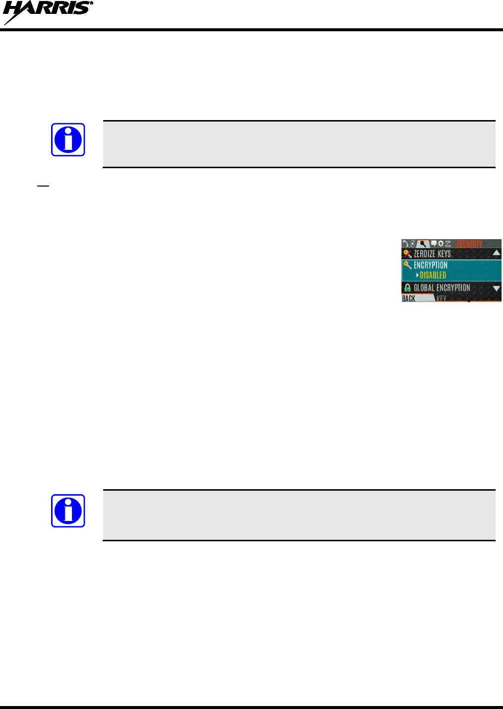
14221-1800-2000, Rev. D
45
For more information on configuring the radio for Voice Annunciation, refer to the Voice Annunciation
Feature manual 14221-7200-6110.
5.19 ENABLE/DISABLE ENCRYPTION
A switch or a button on the radio can be programmed to enable/disable encryption.
See Section 7.4
for the various options that can be programmed to the radio buttons
and switches.
Or
Turn encryption on or off via the Security Menu:
1. Press the Menu/Select button to access the menus.
2. Use the or button to highlight and select the SECURITY menu.
3. Use the or button to highlight ENCRYPTION
. Toggle encryption
enabled/disabled using the Menu/Select button. This option is grayed out if
any switch is programmed for encryption
, or if Encryption Mode in the
radio’s personality is programmed “Forced On.”
• If a channel is programmed to be encrypted, an optional key icon appears on the main display when
encryption is enabled. The system must also be programmed for encryption.
• When encryption is enabled and you use any channel not configured for encryption, the radio allows
PTT. The signal is transmitted unencrypted.
• Systems configured for Global Encryption (enabled in the Security menu) can display an optional
Global Encryption icon in addition to or instead of a key icon (Section 6.20.3).
5.20 TRANSMIT ENABLE/DISABLE
When transmit is disabled, all forms of transmission from the radio are disabled, including Bluetooth.
This is designed for use in explosive atmospheres.
If enabled via programming, use the A/B switch to enable or disable transmit.
See Section 7.4
for the various options that can be programmed to the radio buttons
and switches.
NOTE
NOTE
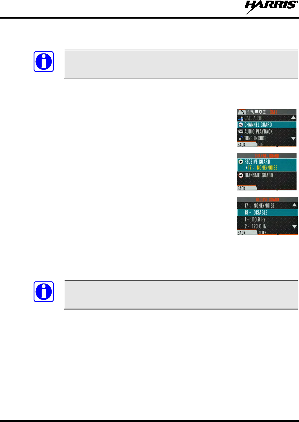
14221-1800-2000, Rev. D
46
5.21 CHANNEL GUARD (ANALOG CONVENTIONAL ONLY)
Channel Guard is Harris’s trademark for CTCSS (tone squelch) and CDCSS (digital tone squelch).
The Channel Guard menu is only accessible if the System is setup for CG SEL in the
radio’s personality.
To select the Channel Guard tone:
1. Press Menu/Select button to access the main menu.
2. Use or to display the CALL menu.
3. Use or to highlight CHANNEL GUARD and press the Menu/Select
button.
4. Use or to highlight RECEIVE GUARD or TRANSMIT GUARD
and press the Menu/Select button.
5. Use or to highlight the desired option from the list and select using
the Menu/Select button.
6. The Channel Guard frequency is displayed on the main display.
The Channel Info screen and Channel Edit screen will change depending on this selection. See Sections
6.4 and 7.2 for more information.
A button on the radio can be programmed for Channel Guard Override (see Section
7.4).
NOTE
NOTE
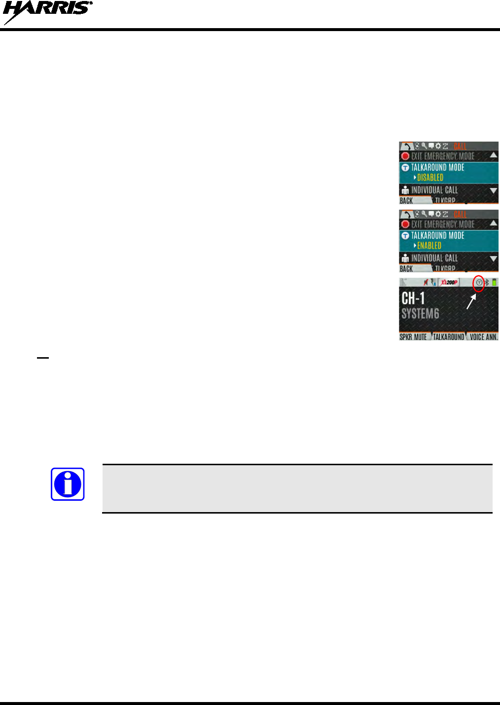
14221-1800-2000, Rev. D
47
5.22 USE TALKAROUND TO BYPASS REPEATER (ANALOG AND P25
CONVENTIONAL ONLY)
You can bypass the repeater system to communicate directly with other radios on your current channel’s
receive frequency. This is useful if you are out of range of a repeater or if a repeater is busy. You will
need to be in range of the other radio.
1. Press Menu/Select button to access the main menu.
2. Press or to display the CALL menu.
3. Press or to highlight TALKAROUND MODE.
4. Press the Menu/Select button to toggle TALKAROUND MODE to
ENABLED.
5. The optional Talkaround icon
appears. Calls are now made on the receive
frequency until you disable talkaround mode via the CALL
menu. Power
cycling the radio does not disable talkaround.
Or
A button or switch can be programmed to toggle talkaround enable/disabled. See Section 7.4 for the
various options that can be programmed to the radio buttons and switches.
If the Talk-Around Indication feature is enabled in RPM2, the radio will play a unique grant tone when a
call is placed on a simplex channel or when Talk-Around has been enabled on a duplex channel. This
feature applies to both Analog and P25 Conventional systems. It optionally allows the radio to also play
the same tone when it receives a call while operating in simplex or Talk-Around. If configured, the radio
plays the tone at the selected volume level.
The tone will not play on systems configured with MDC.
Talk-Around Indication can be specified for each individual Analog and P25 Conventional system
configured in personality. The following options can be selected, and apply only when the radio is on a
simplex channel or when Talk-Around has been enabled by the user:
• Disabled: (This is the default option.) When this option is selected, the radio plays the standard grant
tone when a call is placed. The radio does not play a tone when a call is received.
• Transmit Only: When this option is selected, the radio plays a different “Talk-Around” grant tone
when a call is placed. The radio does not play a tone when a call is received.
• Transmit & Receive: When this option is selected, the radio plays a different “Talk-Around” grant
tone when a call is placed, and at the beginning of a received call.
NOTE
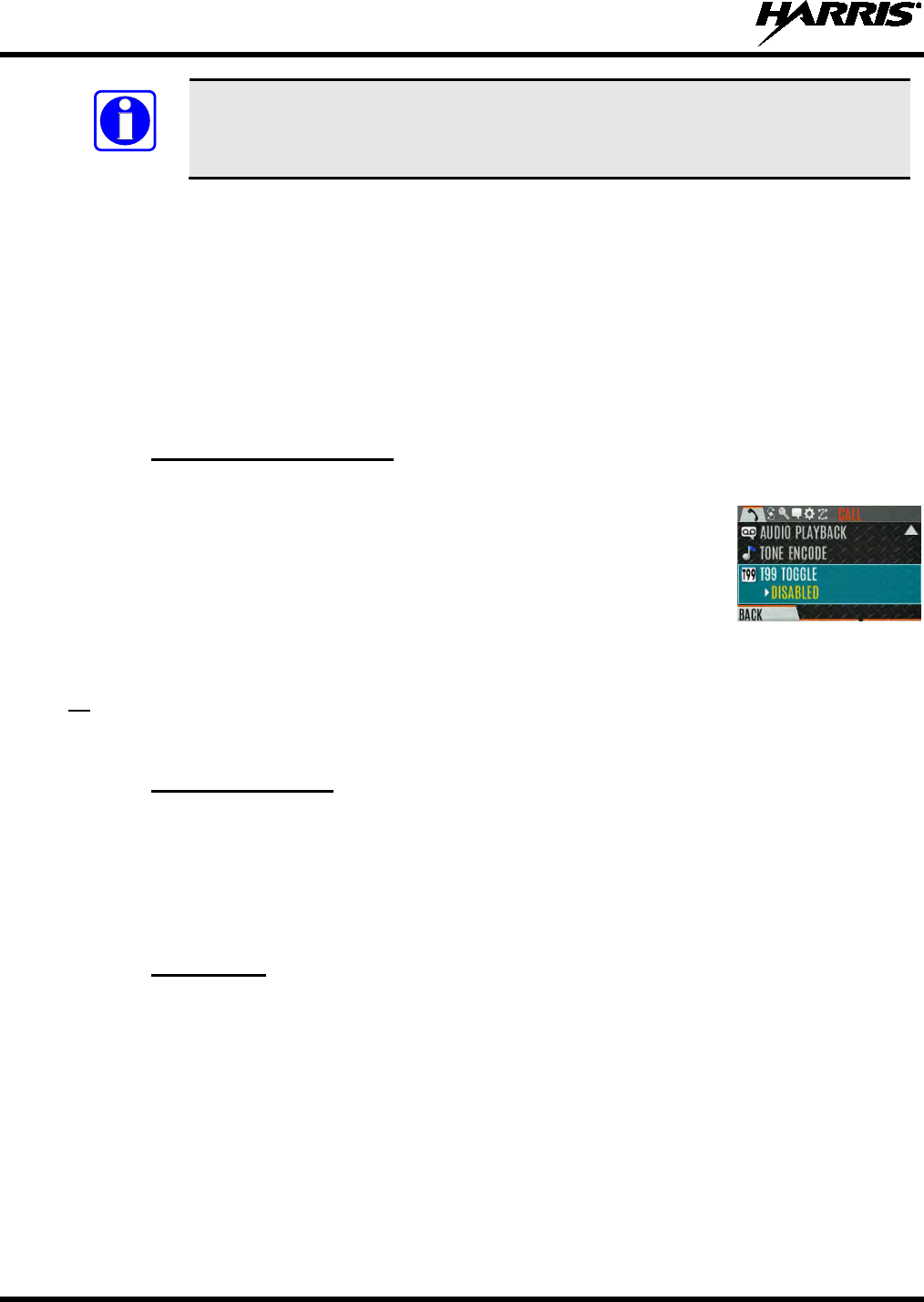
14221-1800-2000, Rev. D
48
In the radio personality, the “Alert Tone” parameter needs to be enabled for each
channel on the Conventional Frequency Set. The “Ready To Talk Tone” parameter
must also be enabled for the Talk Around Indication tone to be played when the radio
is keyed.
5.23 TYPE 99 OPERATION
Type 99 is Harris' name for in-band, two-tone sequential signaling. It is a conventional signaling protocol
used to control the muting and unmuting of a radio. This signaling is commonly used for selective calling
of individual units or groups of units in a conventional system.
In Type 99 tone systems, calls are not heard until the radio detects the proper two-tone sequence. This, in
conjunction with squelch, prevents the user from hearing noise or undesired conversations. When the
radio detects the second tone, it sounds the appropriate Type 99 alert tone. After the second tone stops,
the receiver audio path is opened in order for the user to receive messages.
5.23.1 Enable/Disable Type 99
1. Press Menu/Select button to access the main menu.
2. Press or to display the CALL menu.
3. Press or to highlight T99 TOGGLE.
4. Press the Menu/Select button to change T99 TOGGLE between ENABLED and DISABLED. T99
is displayed in the top of the radio display when Type 99 is enabled.
Or
A button or switch can be programmed to enable/disable Type 99 (see Section 7.4).
5.23.2 Disable After PTT
If this option is programmed in RPM2, Type 99 is disabled after the radio user activates the PTT. This
allows the radio user to monitor traffic on the channel (after a PTT action) without pressing the monitor
button.
Can be used in conjunction with the “Auto Reset” option (see Section 5.23.3) to disable Type 99 after a
PTT and automatically reset, or enable, Type 99 after 30 seconds.
5.23.3 Auto Reset
If this option is programmed in RPM2, Type 99 is automatically reset, or turned back on, after 30
seconds. Can be used in conjunction with the “Disable After PTT” option (see Section 5.23.2) to disable
Type 99 after a PTT and automatically reset, or enable, Type 99 after 30 seconds.
NOTE
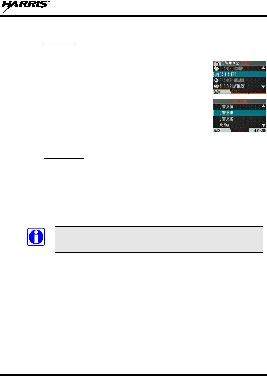
14221-1800-2000, Rev. D
49
5.24 CALL ALERT (PAGE)
5.24.1 Send Alert
1. Press the Menu/Select button to access the main menu.
2. Press or to display the CALL menu.
3. Press or to highlight CALL ALERT
and press the Menu/Select
button.
4. Press or
to highlight the desired unit from the list and press the
Menu/Select button, or select KEYPAD to enter the Unit ID.
5. Press PTT to send the page.
5.24.2 Receive Alert
1. When receiving a Call Alert, the radio displays the calling radio’s name or Unit ID.
2. The radio rings and indicates a missed call. The ring sounds continuously until you press PTT, press
the CLR MISSED softkey, change group/system, or power cycle the radio.
5.25 DTMF
The XL-200P supports the transmission of DTMF tones corresponding to the numbers/characters on the
keypad. To overdial numbers/characters, press and hold the PTT button, and then press the corresponding
keys one at a time on the keypad. Valid keys for DTMF tones are: (1, 2, 3, 4, 5, 6, 7, 8, 9, *, 0, and #).
For conventional or P25 Conventional systems, DTMF tones only play if the current
system is programmed for DTMF (part of general System configuration). DTMF tones
are always enabled for P25 Trunking systems.
5.26 AUDIO PLAYBACK
The Audio Playback feature allows the user to playback a previously received call. Recordings are stored
in the radio’s RAM and are not persistent across power cycles. The radio stores the last five (5) recorded
calls up to 1 minute each.
A button on the radio can be programmed to replay the last recorded call. To playback the last received
call from a button:
1. Press the button programmed for audio playback. The last call received before the button was pressed
is played each time the button is pressed.
2. Additional incoming calls will be recorded in the background, but pressing the button continues to
replay the captured call until reset.
NOTE

14221-1800-2000, Rev. D
50
3. To reset the feature and allow a new call to be captured, press and hold the button until you hear a 2-
tone chirp. At this point the button can be used to capture an new incoming call.
You can also playback one of the last five calls received via the menu. To playback a previously received
call from the menu:
1. Press the Menu/Select button.
2. Press or to display the CALL menu.
3. Press or to highlight AUDIO PLAYBACK
and press the
Menu/Select button.
4. Select the desired call from the list (the most recent call is at the top of the
list) and press the select button. The selected call will be played.
• If a button is also programmed for Audio Playback, pressing the button
replays the call that selected in the menu. The feature must be reset as
above in order to use the button to capture a new call.
• If a button is not programmed for Audio Playback, then you must
navigate back to the menu to play the call again.
Any incoming call that occurs during playback preempts the playback.
5.27 START SCAN
This procedure assumes that the scan list has been added and the radio is not in active scan. Refer to
Section 6.13 for scan setup or Section 5.28 for stopping scan. Refer to Section 6.14.1.1, Section 6.14.1.2,
and Section 6.14.1.3 for home and priority channel descriptions.
1. Press the Menu/Select button to access the main menu.
2. Press or to display the SCAN menu.
3. Press or to highlight START SCAN
and press the Menu/Select
button. START SCAN text changes to STOP SCAN.
4. Press the BACK soft key to exit the scan menu.
5. The scan icon is displayed on the idle display when scanning is enabled.
NOTE
14221-1800-2000, Rev. D
51
Or
1. Press the Menu/Select button to access the main menu.
2. Press or to display the SCAN menu.
3. Press or to highlight SCAN LISTS and press the Menu/Select button.
4. Press or to highlight the desired SCAN LIST and press the START
SCAN soft key.
Or
A switch or button on the radio can be programmed to start/stop scan.
If a switch is programmed for start/stop scan, the menu for starting and stopping scan
is disabled.
See Section 7.4
for the various options that can be programmed to the radio buttons
and switches.
5.28 STOP SCAN
1. Press the Menu/Select button to access the main menu.
2. Press or to display the SCAN menu.
3. Press or to highlight STOP SCAN and press the Menu/Select button.
4. Press the BACK soft key to exit the scan menu.
Or
1. Press the Menu/Select button to access the main menu.
2. Press or to display the SCAN menu.
3. Press or to highlight SCAN LISTS and press the Menu/Select button.
4. Press the STOP SCAN soft key.
NOTE
NOTE
14221-1800-2000, Rev. D
52
Or
A switch or button on the radio can be programmed to start/stop scan.
If a switch or button is programmed for start/stop scan, the menu for
starting and
stopping scan are disabled.
See Section 7.4 for the variou
s options that can be programmed to the radio buttons
and switches.
5.29 MONITOR AND SQUELCH TYPES (CONVENTIONAL ONLY)
The monitor function allows you to temporarily turn off selected squelch to monitor for traffic that may
not normally break squelch. The type of squelch used depends on an analog or digital channel. A button
or switch on the radio can be programmed to start or stop Monitor (see Section 7.4 for the various options
that can be programmed to the radio buttons and switches.).
For analog channels, there is:
• Noise squelch - any received signal breaks squelch.
• Continuous Tone Coded Squelch (CTCSS) - squelch is selective based on tone code.
• Continuous Digital Coded Squelch (CDCSS) - squelch is selective based on digital code.
For digital channels, there is:
• Monitor squelch - any received digital signal breaks squelch.
• Normal squelch - Received Network Access Code (NAC) must be correct to break squelch.
• Selective squelch - Received NAC and talkgroup Identification (ID) or unit ID must be correct to
break squelch.
During encrypted operations, the radio only unmutes when receiving with the same key.
NOTE
NOTE
NOTE
14221-1800-2000, Rev. D
53
5.30 NUISANCE DELETE
A channel can temporarily be deleted from the scan list. The selected channel, priority 1, and priority 2
channels cannot be nuisance deleted.
A button or switch on the radio can be programmed for nuisance delete (see Section 7.4 for the various
options that can be programmed to the radio buttons and switches).
Nuisance delete can only be performed on the active scan list.
To perform nuisance delete from the menu:
1. Press the Menu/Select button to access the main menu.
2. Press or to display the SCAN menu.
3. Press or to highlight SCAN LISTS and press the Menu/Select button.
4. Press or to highlight the scan list and press the Menu/Select button.
When scanning is started, indicates the active scan list; when scanning is
stopped, indicates the active scan list.
5. Press or to highlight the desired channel.
6. Press the OPTIONS soft key.
7. Press or to highlight NUISANCE and press the Menu/Select button.
8. The icon appears next to the channel and it will not be scanned.
9. Highlight the channel, press the OPTIONS soft key, and select ADD
BACK to add channel back to sc
an list. If you do not add the channel back
to the list, the channel will return to the
scan list when you cycle radio power
or activate a personality.
10. Press the BACK soft key to exit the channel list.
11. Press the BACK soft key to exit the scan list display.
NOTE
14221-1800-2000, Rev. D
54
5.31 EMERGENCY OPERATION
The XL-200P can be programmed to enable emergency mode. Unit name displays on dispatcher console
if an emergency signal is received from another XL-200P on a digital channel.
5.31.1 Declaring an Emergency Call
1. Press and hold the emergenc
y button on the radio or the speaker
microphone.
The length of time you need to hold the button is configured in
RPM2.
2. The emergency icon is displayed on the idle display.
• For digital channels, the radio transmits the talkgroup or radio ID to the dispatch console and
receiving radio.
• The radio can be programmed to have a dedicated emergency channel, which can be activated
from analog or digital channels.
•
The radio can also be programmed to send an Emergency Alarm in addition to or in place of the
emergency call (P25 modes).
The radio goes through transmit and receive cycles if so configured. Speak into the microphone while
the radio is transmitting or press PTT to talk.
3. To exit emergency, power cycle the radio or select EXIT EMERGENCY
from the CALL menu.
If enabled via programming, you can clear an emergency by pressing the
button programmed for the
Monitor/Clear function and then the emergency
button.
5.31.2 Receiving an Emergency Call
When receiving an Emergency Call, an alert beep sounds (if tones are enabled) and an emergency
indication is displayed.
The unit ID and/or unit name of the unit in emergency is displayed.
While the emergency display is active, press PTT to respond to the emergency caller.
5.31.3 Stealth Emergency
The radio can be programmed with the following emergency behavior:
• No audio indications when declaring an emergency.
Or
• No visual indications when declaring an emergency.
Or
• No audio and no visual indications when declaring an emergency.
During stealth mode, the radio will not receive any type of call. Once the user presses the PTT button, the
radio display and audio return to normal.

14221-1800-2000, Rev. D
55
5.32 MDC-1200 (ANALOG CONVENTIONAL ONLY)
MDC-1200 is a legacy in-band signaling protocol that provides the radio with the ability to transmit and
receive a unique PTT ID. This PTT ID can be decoded by receiving radios and displayed as a
hexadecimal number or an alias string. In addition, MDC-1200 provides radios with the ability to transmit
emergency status to a console. Refer to the MDC-1200 Feature Manual, 14221-7200-6000, for complete
instructions on configuring and using this feature.
5.32.1 Normal PTT Operation
If MDC signaling on PTT press is enabled in RPM2, the radio transmits an MDC PTT ID message when
PTT is pressed. If the Sidetone option is enabled in RPM2, the radio plays a Ready-to-Talk (RTT) tone
after the MDC pre-signaling has been transmitted.
If MDC signaling on PTT release is enabled (in RPM2), the radio transmits post-call MDC signaling
when PTT is released.
• IF STE is enabled (in RPM2), the MDC post-call signaling is transmitted after STE is sent on PTT
release only.
• MDC post-call signaling is also sent when there is a radio unkey due to Carrier Control Timeout
(CCT). Normal CCT alert tones occur prior to unkey.
5.32.2 MDC PTT ID Receive Handling
When the radio receives an MDC PTT ID, it searches the MDC ID Alias List for an alias associated with
the ID. If one is found, it displays the alias. If none is found, the radio displays the ID in hexadecimal.
5.32.3 Emergency Declaration
Emergency declaration is accomplished by the radio generating an MDC Emergency PTT message. An
Emergency is considered acknowledged when the radio receives an “Ack To Emergency” PTT message
with an ID which matches its own ID. If Emergency Audio is enabled and the PTT Sidetone option is
enabled, the radio plays the Ready-to-Talk tone after the MDC Emergency PTT signaling is transmitted.
• If an MDC Alert on ACK is enabled, the radio plays an ACK tone when the MDC emergency is
acknowledged.
• If audio tones are enabled, the radio plays an ACK tone if the emergency is not acknowledged within
the programmed number of retries.
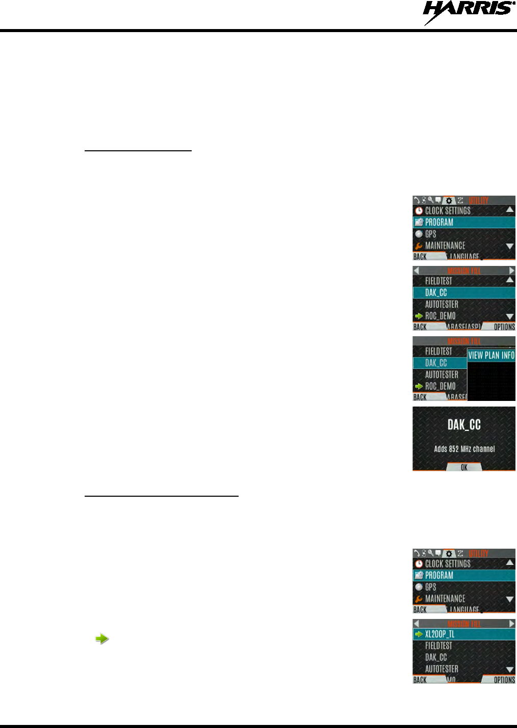
14221-1800-2000, Rev. D
56
6. ADVANCED OPERATIONS
6.1 VIEW/CHANGE PERSONALITIES
Personalities contain radio programming information such as frequencies, channels, stations, and talk
groups. Up to 10 different personalities can be stored in the radio, but only one can be activated at a time.
6.1.1 View Personalities
To view a personality:
1. At main display, press the Menu/Select button to access the main menu.
2. Press or to display the UTILITY menu.
3. Press or to highlight PROGRAM and press the Menu/Select button.
An arrow indicates the currently active personality.
4. Press the OPTIONS soft key.
5. Select VIEW PLAN INFO to view.
6. The radio displays the plan’s filename. Personality information appear
s if
the field was filled out in RPM2.
6.1.2 Change Active Personality
To change the active personality:
1. At main display, press the Menu/Select button to access the main menu.
2. Press or to display the UTILITY menu.
3. Press or to highlight PROGRAM and press the Menu/Select button.
4. Press or to highlight the desired personality and press the Menu/Select
button. indicates the currently active personality.
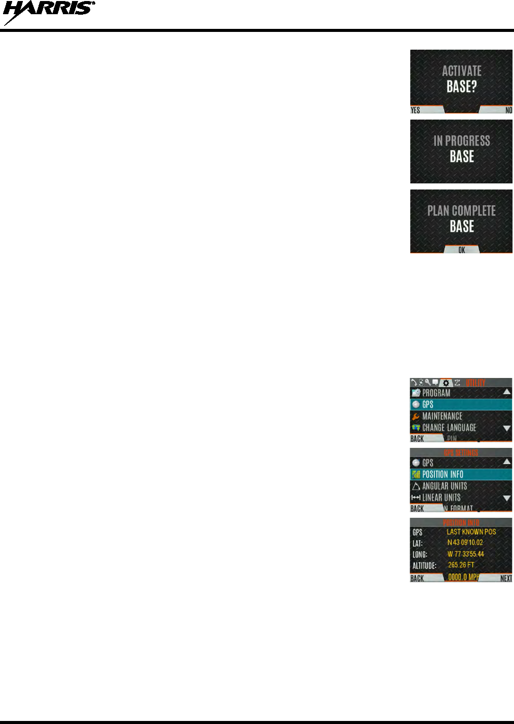
14221-1800-2000, Rev. D
57
5. Press the YES soft key to confirm personality activation. If the personality
has a power-up PIN, you are
prompted to enter the PIN before activation
continues.
6. The IN PROGRESS
screen is displayed while plan activation is in
progress.
7. If personality is activated, the radio displays PLAN COMPLETE followed
by the name of the personality. Press the OK soft key.
•
You cannot activate a personality when the radio is transmitting an
emergency.
• A FAILED message may be displayed for errors such as invalid syntax
in the fill or some other invalid parameter.
6.2 SITUATIONAL AWARENESS (SA) – P25 CONVENTIONAL ONLY
Situational Awareness is a feature in which the XL-200P receives SA position from other units
configured to send the SA packets. The SA display shows the positions of the other radios (units) relative
to the XL-200P. To make use of SA, all radios need to have a uniquely programmed Unit ID.
1. Press the Menu/Select button to access the main menu.
2. Press or to display the UTILITY menu.
3. Press or to select GPS and press the Menu/Select button.
4. Press or to select POSITION INFO and press the Menu/Select
button.
5. Press the NEXT soft key.
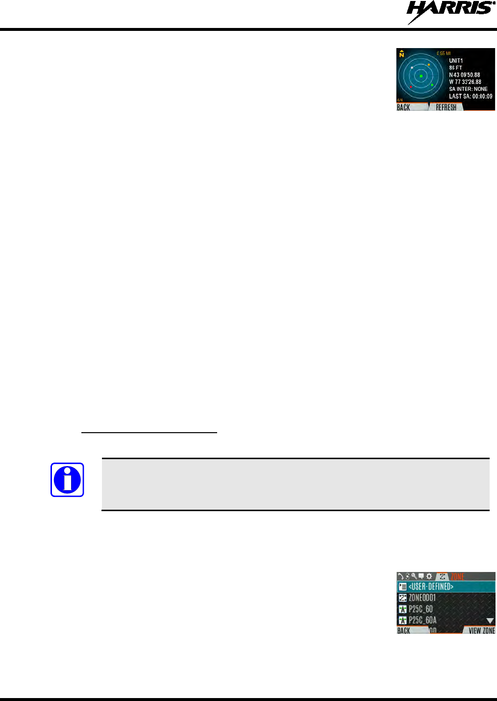
14221-1800-2000, Rev. D
58
6. Press or to view the location of each unit.
The color of each unit
indicates its status as follows. Only one status can be shown at a time and
are listed in priority order:
• Grey – Unselected, no status
• Red – Unselected, In Emergency
• Orange – Unselected, Low Battery
• Blue - Unselected, Scanning
• Green – Selected, no status
• Green/Red – Selected, In Emergency
• Green/Orange – Selected, Low Battery
• Green/Blue - Selected, Scanning
7. GPS of this radio is shown by the center dot as follows:
• Green – Tracking
• Orange – Last known position
• Red – Searching
8. Press
or
to zoom the display distance of current unit.
9. Press the OPTIONS soft key. From here, select UNIT INFO
to display
details about the selected unit, select REFRESH to
update information, or
select EXIT.
6.3 USER-DEFINED ZONES/SYSTEMS
6.3.1 Command Tactical Zone
A Command Tactical Zone is defined at the radio.
A Command Tactical Zone is reset when a Personality is activated.
To create a Command Tactical Zone:
1. Press the Menu/Select button to access the main menu.
2. Press or to display the ZONE menu.
3.
Press or to highlight <USER-DEFINED> and press the
VIEW ZONE
soft key.
NOTE
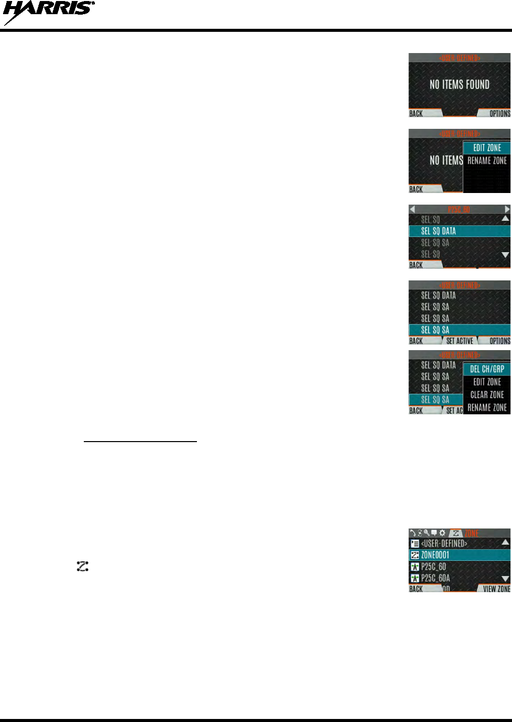
14221-1800-2000, Rev. D
59
4. Press the OPTIONS soft key.
5. Press or to select EDIT ZONE to create a zone, or RENAME
ZONE to rename the Command Tactical Zone
(up to 16 characters are
allowed).
6. Press or to scroll through existing systems. Press or to
highlight desired channel/group.
7. Press the Menu/Select button to add or remove channel/group.
8. After adding all desired channels/groups, press the BACK soft key.
9. Activate the Command Tactical Zone by selecting the SET ACTIVE soft
key on the USER DEFINED screen, or by pressing the Menu/Select
button when <USER DEFINED> is highlighted on the Zone menu.
10. After a creating a Command Tactical Zone, select OPTIONS to edit the
Command Tactical Zone, delete channels/groups, clear the zone, and
rename the zone.
6.3.2 Mixed System Zone
Mixed System Zones are defined in RPM2 and cannot be edited on the radio. If a Mixed System Zone is
not configured in RPM2, it will not appear on the radio. Up to 50 Mixed System Zones can be defined.
You can view details about each channel/group. A user programmable button can be defined to scroll
through just the mixed system zones.
1. Press the Menu/Select button to access the main menu.
2. Press or to display the ZONE menu.
3. Press or to highlight the desired zone (Note: Zones are indicated by
the icon) and select VIEW ZONE
to view the groups/channels in the
zone list.
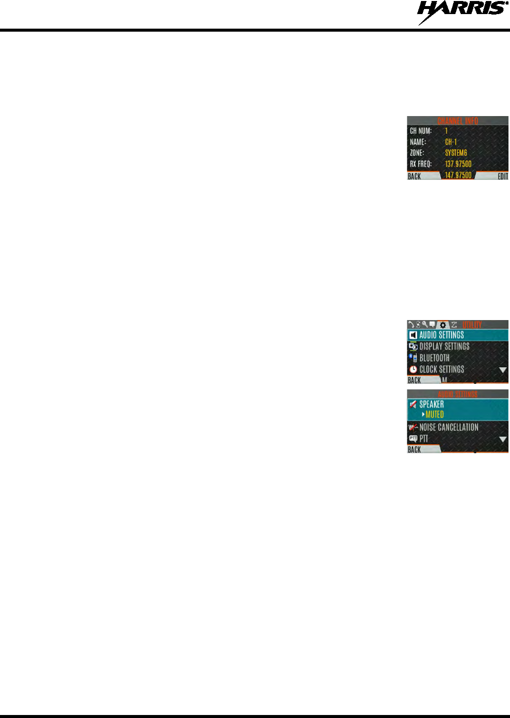
14221-1800-2000, Rev. D
60
6.4 CH INFO MENU
The Channel Information (CH INFO) menu displays information about the currently selected channel.
The information displayed varies between conventional and trunked systems.
1. Press
while on the idle display.
2.
Press or to scroll through the programmed channel settings.
CONVENTIONAL
OR P25 CHANNELS ONLY:
3.
Press the EDIT soft key.
4.
Enter the password
. You may now select and change the values of the displayed channel parameters.
The password remains active until power cycle. Refer to Section 7.2 for more information.
6.5 AUDIO SETTINGS
Set audio settings such as speaker mute, noise cancellation, PTT, and tones.
1. Press the Menu/Select button to access the main menu.
2.
Press or to display the UTILITY menu.
3.
Press or highlight AUDIO SETTINGS
and press the Menu/Select
button.
4.
Press or
to scroll through available audio settings. Press the
Select/Menu button to change settings as desired:
• SPEAKER - Mute or Unmute the speaker audio.
• NOISE CANCELLATION - Enable or disable noise cancellation
.
Noise cancellation reduces background noise during transmit.
• PTT - Enable or disable Push-To-Talk (PTT). Disable PTT
to prevent
accidental keying, such as when the radio is in a
holster or you are
getting into a car.
• TONES - Enable or disable alert tones (see Table 5-6).
• KEYPAD TONES -
Enable or disable keypad tones. When enabled, the
radio plays a tone when a button on the keypad is pressed.
5. Press the BACK soft key to exit menu.
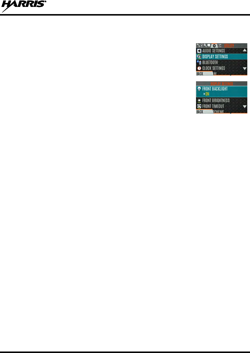
14221-1800-2000, Rev. D
61
6.6 DISPLAY SETTINGS
1. Press the Menu/Select button to access the main menu.
2.
Press or to display the UTILITY Menu.
3.
Press or
to highlight DISPLAY SETTINGS and press the
Menu/Select button.
4.
Press or and the Select/Menu button to change settings as desired:
• COLOR SCHEME -
Change the color scheme of the top and front
displays for optimum viewing in day/night conditions.
• FRONT BACKLIGHT -
Turn front display backlight on, off, or
momentary.
• FRONT BRIGHTNESS -
Set brightness level of front display. A level
of 0 has same effect as turning off backlight.
• FRONT TIMEOUT -
Specify how long the radio needs to be inactive
before the front display’s backlight turns off.
• TOP BACKLIGHT -
Specify how long the top display’s backlight will
remain lit: MOMENTARY, ON, or OFF.
• TOP BRIGHTNESS -
Set the brightness level of the top display. A
level of 0 turns off top display and indicator (TX/RX) LED.
• TOP TIMEOUT -
Specify how long the radio needs to be inactive
before the top display’s backlight turns off.
• TOP ORIENTATION -
Set orientation of top display to be viewed from
radio: FRONT, BACK, or AUTO.
When AUTO is selected, the XL-
200P changes top display to be
viewed from back if an external microphone or speaker is attached.
Otherwise, the display can be viewed from the front.
• INDICATOR LED - Toggle the indicator LED ON/OFF.
5. Press the BACK soft key to exit the menu.
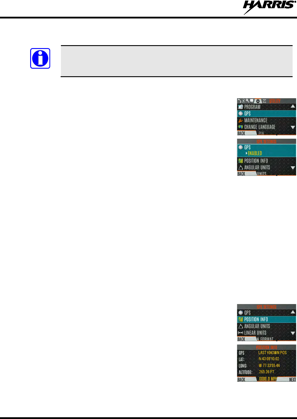
14221-1800-2000, Rev. D
62
6.7 GPS SETTINGS
The GPS SETTINGS menu item only appears if enabled in RPM2 and the feature is
installed.
1. Press the Menu/Select button to access the main menu.
2.
Press or to display the UTILITY menu.
3.
Press or to highlight GPS SETTINGS
and press the Menu/Select
button.
4.
Use or and the Select/Menu button to change settings as desired:
• GPS - Enable or disable internal GPS.
• POSITION INFO - See Section 6.8.
• LINEAR UNITS -
Set unit of measurement of displayed linear units:
STATUTE, METRIC, or NAUTICAL.
• ANGULAR UNITS -
Set unit of measurement of displayed angular
units: CARDINAL, DEGREES, or MILS.
• POSITION FORMAT- Set format
of displayed position information:
Latitude/Longitude Degrees Minutes Seconds (LAT/LONG DMS
),
LAT/LONG DM, Military Grid Reference System (MGRS),
or
Universal Transverse Mercator (UTM).
5.
Press the BACK soft key to exit the menu.
6.8 POSITION INFO
The Position Info screen displays the radio user’s location information. GPS must be enabled in the GPS
Settings (see Section 6.7).
1. Press the Menu/Select button to access the main menu.
2.
Press or to display the UTILITY menu.
3.
Press or to highlight POSITION INFO
and press the Menu/Select
button.
4.
Press or to scroll through available location information.
NOTE
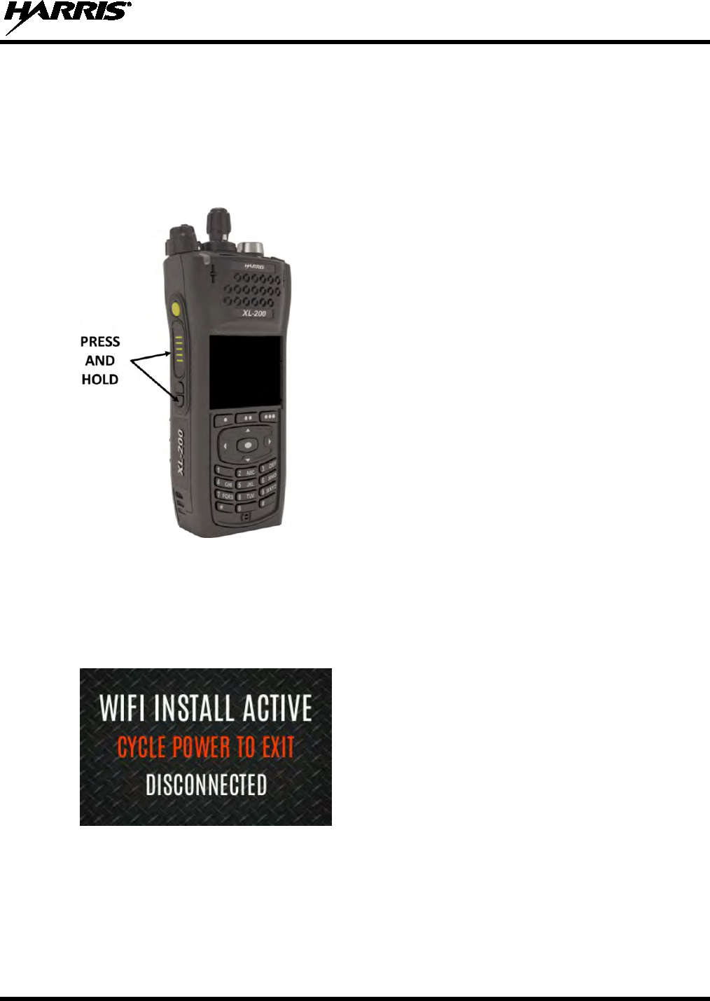
14221-1800-2000, Rev. D
63
6.9 WI-FI
The XL-200P supports programming via Wi-Fi. Refer to Appendix A for information on configuring Wi-
Fi.
To enable Wi-Fi programming mode on the radio:
1. Ensure the radio is powered off.
2. Press and hold the bottom side button and PTT button (see Figure 4-1).
Figure 6-1: Enabling Wi-Fi
3. Power on the radio.
4. The WIFI INSTALL ACTIVE screen is displayed (Figure 6-2). The radio displays
DISCONNECTED if not connected to a wireless network, or CONNECTED if connected to a
wireless network.
Figure 6-2: Wi-Fi Install Active
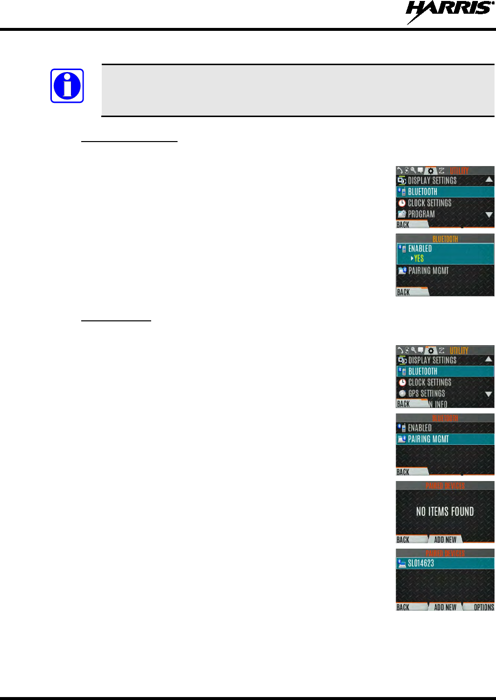
14221-1800-2000, Rev. D
64
6.10 BLUETOOTH
The BLUETOOTH menu item only appears if enabled in RPM2 and if the feature is
installed.
6.10.1 Enable Bluetooth
1. Press the Menu/Select button to access the main menu.
2. Press or to display the UTILITY menu.
3. Press or to highlight BLUETOOTH
and press the Menu/Select
button.
4. Press or to highlight ENABLED and press the Menu/Select button to
toggle YES/NO.
6.10.2 Pair Devices
1. Press the Menu/Select button to access the main menu.
2. Press or to display the UTILITY menu.
3. Press or to highlight BLUETOOTH
and press the Menu/Select
button.
4. Press or to highlight PAIRING MGMT
and press the Menu/Select
button.
5. Make sure device being paired is power
ed on and has discovery mode
enabled in order to pair with the XL-200P.
If no devices are found and Bluetooth is enabled, only the ADD NEW soft
key is available. If devices are paired, the OPTIONS soft key appears.
6. Press the ADD NEW soft key to select a device to pair.
NOTE
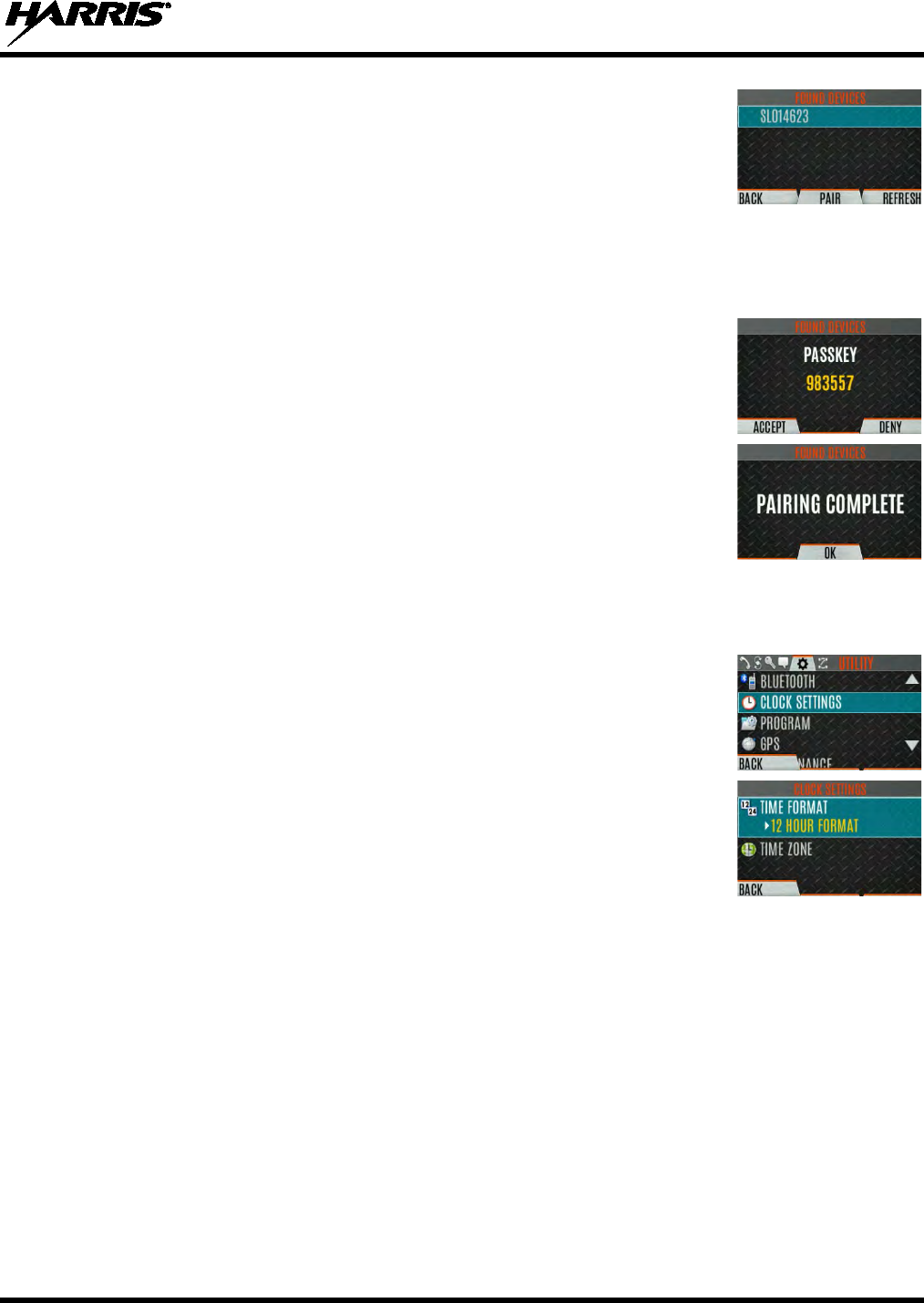
14221-1800-2000, Rev. D
65
7. A list of available Bluetooth devices appears.
8. Press the REFRESH soft key to refresh the device list if the desired device
does not appear.
9. Press
or
highlight the desired device and press the PAIR softkey.
10. Pairing progress is displayed.
• For Bluetooth 2.0 devices, a pin code screen appears.
Enter the pin code and select OK.
• For Bluetooth 2.1 devices, a PASSKEY accept/deny screen appears.
Select ACCEPT.
Accept the passkey on the Bluetooth 2.1 device as well.
11. A message appears when pairing is complete. Select OK. The paired device
is then displayed in the PAIRED DEVICES list.
6.11 CLOCK SETTINGS
1. Press the Menu/Select button to access the main menu.
2. Press or to display the UTILITY menu.
3. Press or to highlight CLOCK SETTINGS and press the Menu/Select
button.
4. Use or and Menu/Select button to change settings as desired:
• TIME FORMAT- Set 12 or 24 hour time display format.
• TIME ZONE -
Set time zone relative to Universal Time Coordinated
(UTC).
5. Press the BACK soft key to exit.
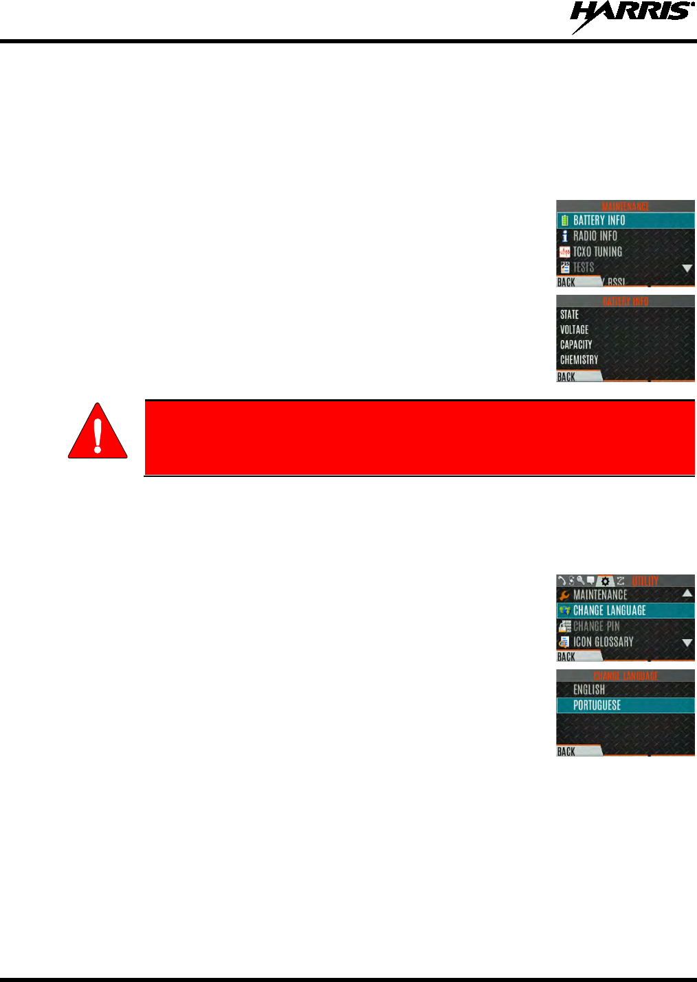
14221-1800-2000, Rev. D
66
6.12 BATTERY SETTINGS
1. Press the Menu/Select button to access the main menu.
2. Press
or
to display the UTILITY menu.
3. Press or to highlight MAINTENANCE
and press the Menu/Select
button.
4. Press or to highlight BATTERY INFO and press th
e Menu/Select
button.
5. Battery information is displayed (state, voltage, capacity, and chemistry).
Use only Harris approved batteries. Injury could occur from using incorrect
battery.
6.13 SELECT LANGUAGE
To change the language displayed by the XL-200P:
1. Press the Menu/Select button to access the main menu.
2. Press or to display the UTILITY menu.
3. Press or to highlight CHANGE LANGUAGE
and press the
Menu/Select button.
4. Press or to highlight the desired language and press the Menu/Select
button.
WARNING
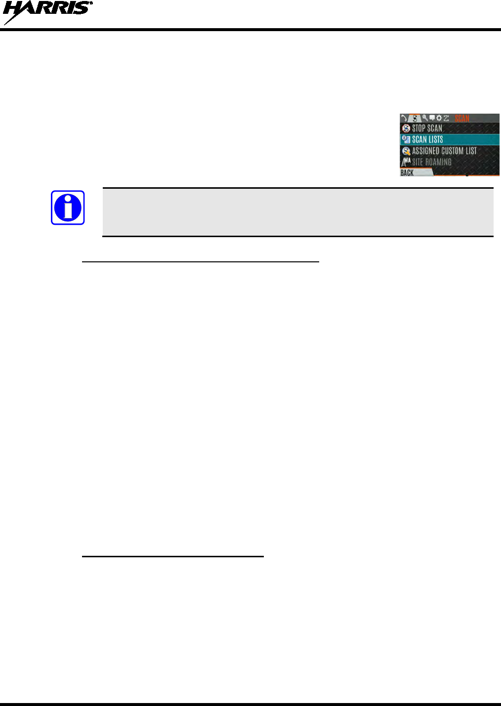
14221-1800-2000, Rev. D
67
6.14 SET UP SCAN
These procedures are used to set up the scan list, home channels, and priority channels.
1. Press the Menu/Select button to access the main menu.
2. Press or to display the SCAN menu.
3. Press or to highlight SCAN LISTS and press the Menu/Select button.
Refer to the following sections.
When using Preemptive Priority Scan, the frequencies in the list need to be unique.
6.14.1 Default, Priority 1, and Priority 2 Channels
6.14.1.1 Default Channel
This is the currently selected channel and is the channel you transmit on by default when you press PTT
while the radio is actively scanning and is not responding to a just received call. Responding to a call the
radio just received while scanning is called hang time. If hang time is set to 0 in RPM2, the radio always
transmits on the default channel in scan.
6.14.1.2 Priority 1 Channel
This channel will be scanned more often than other channels in the list and will be scanned in between
every other channel in the scan list. An example scan sequence would be P1 (priority 1), C2, P1, C3, P1,
C4, etc. In addition, the priority channel will be scanned even while actively receiving on a non-priority
channel. For example, if the radio is actively receiving on C3 and activity is detected on P1, the radio will
drop C3 and switch to P1.
6.14.1.3 Priority 2 Channel
This channel will also be scanned more often than others. An example scan sequence would be P1, C2,
P1, C3, P1, C4, P2, C5, P1, C6, P1, C7, P1, C8, P2, C9 etc. In addition, this channel will be scanned even
while actively receiving on a non-priority channel. For example, if the radio is actively receiving on C3
and activity is detected on P2, the radio will drop C3 and switch to P2. Additionally, activity on P1 can
also preempt P2, but P2 cannot preempt P1.
6.14.2 Trunked/Conventional Scanning
Trunked/conventional scanning adds the ability to scan multiple conventional and P25 conventional
channels while still maintaining P25 trunked radio operation. In essence, the radio is able to scan a
conventional scan list while still receiving a P25 trunked control channel and receiving P25 trunked
calls. Selection of which conventional scan list is associated with a given trunked system is done in
RPM2 and cannot be changed on the radio. However, a user with access to the necessary menu layout
(see Section 5.8) is allowed to edit the scan list members (both trunked groups and conventional channels
on the selected Conventional Priority System). As the number of conventional channels being scanned
increases, the time between scanning each channel increases (roughly 250 milliseconds per channel), with
NOTE
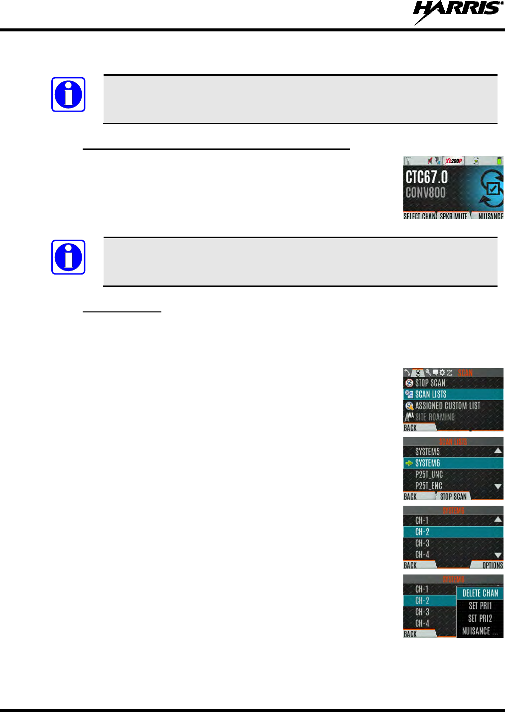
14221-1800-2000, Rev. D
68
the consequent increase in the number of calls that will late-enter. In order to avoid missing calls, it is
recommended to keep the number of conventional channels being scanned to eight (8) or fewer.
The trunking site must have roaming set to Enhanced CC.
6.14.3 Vote Scan (Analog and P25 Conventional Only)
If vote scan is enabled via RPM2, the radio automatically selects the strongest
signal ensuring that the best audio quality is delivered to the user. If vote scan is
enabled, the radio is always scanning. You cannot stop scanning, start normal
scanning, or monitor the channel. The scanning icon on the idle screen indicates
that the radio is vote scanning versus, regular scanning.
If Talkaround is enabled, Vote Scan is disabled until Talkaround is disabled again.
6.14.4 Edit Scan List
Depending on the scan list options selected in RPM2, you may be able to add or remove channels/groups
from the scan list.
1. Press the Menu/Select button.
2. Press or to display the SCAN menu.
3. Press or to select SCAN LISTS.
4. Press or to highlight the scan list and press the Menu/Select button.
5. Press or to highlight channel/group.
6. Select OPTIONS.
7. Press or to select ADD CHAN/DELETE CHAN, SET PRI1, SET
PRI2, REMOVE PRI, or NUISANCE/ADD BACK.
When a channel is not grayed out in the list, DELETE
CHAN
appears. When a channel/group is grayed out (not in list), ADD CHAN
appears.
8. Press the Menu/Select button to toggle selection.
NOTE
NOTE
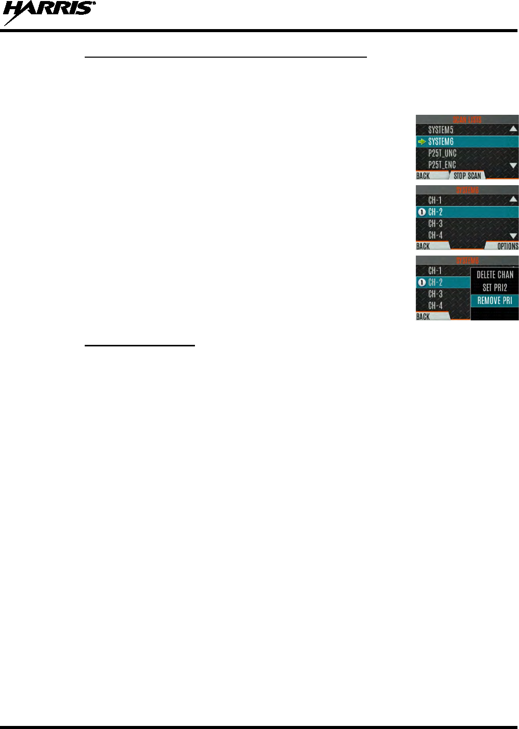
14221-1800-2000, Rev. D
69
6.14.5 Set or Remove Priority 1 and Priority 2 Channels
Priority channels are scanned more often than non-priority channels. Note that P1 and P2 can only be set
if configured as “Keypad” and the scan list is not set to “Fixed” in RPM2.
1. Press the Menu/Select button.
2. Press or to display the SCAN menu.
3. Press or to highlight SCAN LISTS and press the Menu/Select button.
4. Press or to highlight channel/group.
5. Select OPTIONS.
6. Press or
to highlight SET PRI1 or SET PRI2 and press the
Menu/Select button. A Priority 1 channel appears with a P1 and a Priority 2
channel appears with a P2.
7. Select REMOVE PRI to remove priority.
6.14.6 Custom Scan Lists
The Mixed Zone Scan (MZS) feature gives the user the capability to scan based on a custom scan list that
is assigned at the system level. The Custom Scan (CS) list can contain System and Channel/Group
configurations across P25 Trunked, P25 Conventional, and Analog Systems. When a Custom Scan List is
assigned to a P25T system, the radio can scan P25T, P25C and Analog systems. When assigned to a
P25C or Analog system, the radio only scans conventional channels. MZS also gives the user the
capability to scan beyond the selected system group set.
• P25T Scan
When a custom scan list is assigned to a P25T system, the user has the ability to scan P25T, P25C,
and Analog groups/channels. All P25T systems must have the same WACN, System ID, and Unit ID
to be added to the custom scan list. If P25C and/or analog channels are added to the custom scan list,
the radio will scan them using the Trunked/Conventional scan feature described in section 6.14.2, and
will override any other conventional scan list that may have been programmed in RPM2.
• P25C and Analog Scan
When a custom scan lists is assigned to a P25C or Analog System, the user has the ability to scan
P25C and Analog channels. P25T systems are ignored.
Custom scan list can be created in RPM or at the radio. The radio supports up to 10 Custom Scan lists,
with up to 100 channels/groups in each.
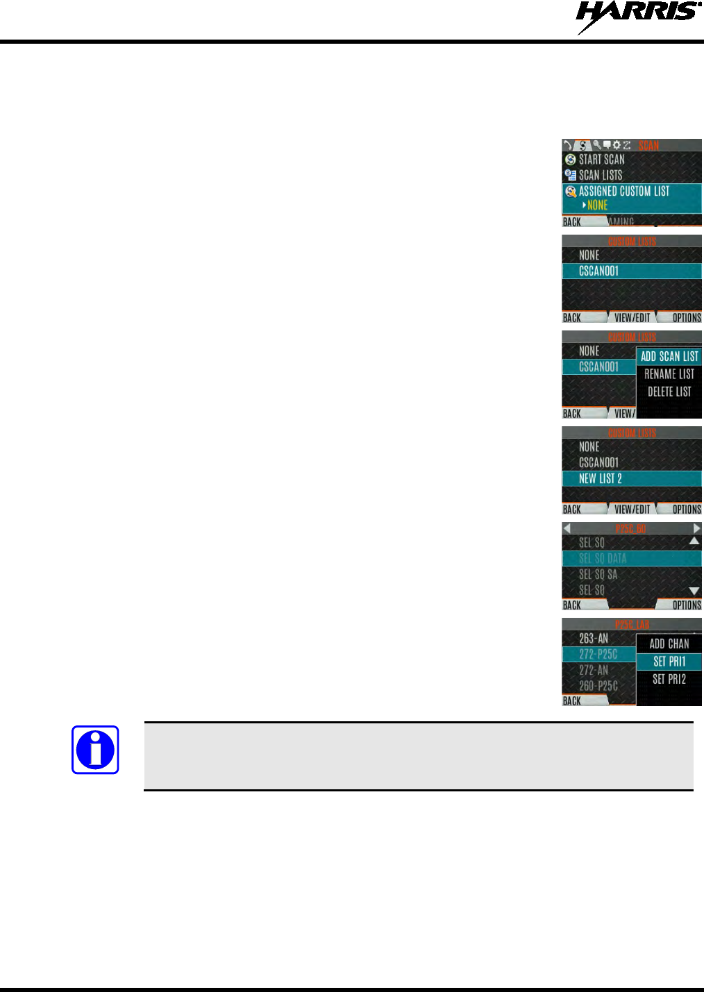
14221-1800-2000, Rev. D
70
6.14.6.1 Create Custom Scan List
To create a custom scan list at the radio:
1. Press the Menu/Select button.
2. Press or to display the SCAN menu.
3. Press or to highlight ASSIGNED CUSTOM LIST
and press the
Menu/Select button.
4. Press the OPTIONS softkey.
5. Select ADD SCAN LIST.
6. Press or to highlight
the newly added scan list and press the
VIEW/EDIT soft key.
7. Press or to display the desired system.
8. Press or to highlight th
e desired group/channel and press the
OPTIONS softkey.
From here, you can add/delete channels from the scan
list, and set/remove Priority 1 and Priority 2 channels.
When a custom scan list is selected, that list is scanned any time scanning is enabled
for any Trunked, conventional, or P25 Conventional system. To scan only the channels
assigned to a particular system, custom scanning must be turned off.
NOTE
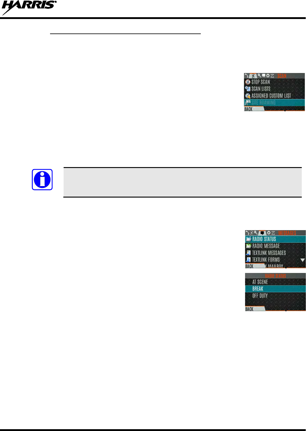
14221-1800-2000, Rev. D
71
6.14.7 Wide Area System Scan (P25 Trunked Only)
Wide Area System Scan (WASCAN) causes the radio to roam across mobile systems when the currently
selected system's control channel is lost. The radio will scan the control channels of other systems.
1. Press the Menu/Select button to access the main menu.
2. Press or to display the SCAN menu.
3. Press or to highlight SITE ROAMING
and press the Menu/Select
button to toggle Wide Area System Scan ENABLED/DISABLED.
4. Select BACK to exit the scan menu.
6.15 RADIO STATUS
The status feature is used to send a particular status condition to the site without making a voice call.
There can be up to 10 status conditions programmed into the radio. For each status defined, there is an ID
and an alphanumeric name. The ID is sent to the site and the alphanumeric name appears on the radio
display when the ID corresponds with the information programmed at the site.
A button on the radio can be programmed to send a radio status (see Section 7.4).
1. Press the Menu/Select button to access the main menu.
2. Press or to display the MESSAGES menu.
3. Press or to highlight RADIO STATUS
and press the Menu/Select
button.
4. Use or and the Menu/Select button to highlight and select desired
status.
NOTE
14221-1800-2000, Rev. D
72
6.16 RADIO MESSAGE
The message feature is used to send a particular message to the site without making a voice call. There
can be up to 10 messages programmed into the radio. For each message defined, there is an ID and an
alphanumeric name. The ID is sent to the site and the alphanumeric name appears on the radio display
when the ID corresponds with the information programmed at the site.
A button on the radio can be programmed to send a radio message (see Section 7.4).
1. Press the Menu/Select button to access the main menu.
2. Press or to display the MESSAGES menu.
3. Press or to highlight RADIO MESSAGE
and press the Menu/Select
button.
4. Use or and the Menu/Select button to highlight and select
the desired
message.
6.17 RADIO TEXTLINK
Radio TextLink provides short text messaging functionality for radios. Because of the difficulty of
entering text messages on a radio, predefined "canned" messages and predefined replies can be stored in
the radio. To facilitate sending messages where information must be provided at send time, text message
forms will also be stored in the radio. A form contains up to four (4) text prompts, for which the operator
enters alphanumeric values before sending the message.
6.17.1 Radio TextLink Messages
1. Press the Menu/Select button to access the main menu.
2. Press or to display the MESSAGES menu.
3. Press or to highlight TEXTLINK MESSAGES
and press the
Menu/Select button.
4. Press or to display the desired message.
• Press the Menu/Select button to send the message.
• Select CHG CALLEE to change the destination for the message.
• Select TOD QUERY to get the time of day.
NOTE
14221-1800-2000, Rev. D
73
6.17.2 Radio TextLink Forms
Form messages are displayed and stored in the radio as a message in which each field to be filled is
indicated by a question mark (?) followed by one or more asterisks(*). The number of asterisks indicates
the maximum number of alphanumeric characters allowed for that field.
1. Press the Menu/Select button to access the main menu.
2. Press or to display the MESSAGES menu.
3. Press or to highlight TEXTLINK FORMS and press the Menu/Select
button.
4. Press or to display
the desired message and press the Menu/Select
button.
5.
Enter text into blank field(s) (up to eight alphanumeric characters) and press
the NEXT soft key.
6. Select SEND to send the message. Select CHG CALLEE
to change the
destination for the message. Select TOD QUERY to get the time of day.
6.17.3 View Received Messages
When the icon appears on the idle display, there are Radio TextLink messages waiting to be read.
1. Press the Menu/Select button to access the main menu.
2. Press or to display the MESSAGES menu.
3. Press or to highlight TEXTLINK MAILBOX
and press the
Menu/Select button. From the mailbox, select OPTIONS
to delete
messages, view details of messages, and reply to messages.
14221-1800-2000, Rev. D
74
6.18 FAULTS/ALERTS
is displayed on the idle display when there is a fault. To view and clear faults/alerts:
1. Press the Menu/Select button to access the main menu.
2. Press or to display the MESSAGES menu.
3. Press or to highlight FAULTS/ALERTS
and press the Menu/Select
button.
4. Fault messages are displayed. Press or to highlight the desired fault.
Press the OPTIONS soft key delete faults. Press the DETAILS soft key to
view details for the highlighted fault.
Possible faults include:
• BATTERY FAULT- Replace battery.
• EEPROM FAULT - Contact Harris.
• RF FAULT - Contact Harris.
• OVERCURRENT -
Check antenna and antenna connection. Try
replacing antenna.
• INVALID SYSTEM - Feature not installed.
• CHANNEL FAULT -
Channel frequency programmed is not valid for
this radio.
5. If you view but do not delete the fault, the alert icon goes away on the idle display.
Contact Harris for assistance with diagnosing a fault.
NOTE
14221-1800-2000, Rev. D
75
6.19 TONE ENCODE
Tone Encode is a generic tone encoding scheme for call identification when transmitting on a
conventional system. It supports generic user-definable tone encode (up to 15 tones), Type 99 (up to 2
tones) and 5/1 Tone (up to 5 tones) encoding formats.
Tone encoding schemes are used to transmit calls to one or more target radios that have been programmed
with the correct tone decode sequence. When the receiving radio detects its tone decode sequence, it
unmutes on the call.
1. Press the Menu/Select button to access the main menu.
2. Press or to display the CALL menu.
3. Press or to highlight TONE ENCODE
and press the Menu/Select
button.
4. Select the desired Tone Encode option from the list.
6.20 ENCRYPTION
6.20.1 Create and Load Keys
Refer to the following documentation for advanced programming and setup instructions:
• Harris OTAR Overview Manual - MM-008069-001
• Network Key Manager Installation and Configuration Manual - MM-008070-001
• Harris UAS Key Management Application Manual - MM-008068-001
• Harris Key Manager Key Admin Overview and Operation Manual - MM1000019423
• Harris Key Manager Key Loader Overview and Operation Manual - MM1000019424
• Motorola® KVL 3000 Plus Key Variable Loader (KVL) User's Guide
• Motorola KVL 4000 Key Variable Loader (KVL) User's Guide
14221-1800-2000, Rev. D
76
6.20.2 Zeroize Keys from Radio
It may be necessary to remove keys because of compromise or expiration.
1. Press the Menu/Select button to access the main menu.
2. Press or to display the SECURITY menu.
3. Press or highlight ZEROIZE KEYS
and press the Menu/Select
button.
4. Press the YES softkey to remove the keys.
This will also remove the
keysets.
6.20.3 Protected Keys
The Protected Keys feature transfers P25 Voice Keys, from Harris Key Loader to the radio, that have
been wrapped (AES) or encrypted (DES) with Key Protection Keys (KPKs). KPKs are nothing more than
unprotected Key Encryption Keys (KEKs). The KPKs need to be loaded into the radio before the
Protected Keys are loaded. Once loaded into the radio, the KPKs are used to unwrap (AES) or decrypt
(DES) the Protected Keys.
6.20.4 Global Encryption
Global Encryption can be enabled when encryption keys are loaded on the radio and the selected
Zone/System is encrypted. When Global Encryption is enabled on the radio, a Global Key is used for all
encrypted transmissions until:
• Global Encryption is disabled.
• A new personality is activated.
• The active keyset is changed.
• The system is changed.
Global Encryption behavior is available on all channels that support encrypted communications.
1. Press the Menu/Select button to access the main menu.
2. Press or to display the SECURITY menu.
3. Press or to highlight GLOBAL ENCRYPTION. Press the
Menu/Select button.
14221-1800-2000, Rev. D
77
4. Press or to highlight the desired Global Key and press the Menu/Select
button to enable Global Encryption.
5. To change the selected global key, press or to highlight GLOBAL
KEY on the SECURITY menu. Press the Menu/Select key.
6. Press or to highlight the global key and press the Menu/Select button.
RPM2 allows Key Numbers to be given Key Names.
7. The optional global key icon is displayed on the main display.
6.20.5 Select Keyset
1. Press the Menu/Select button to access the main menu.
2. Press or to display the SECURITY menu.
3. Press or to select ACTIVE KEYSET.
Press the Menu/Select button
to toggle to the inactive keyset.
6.20.6 View Key List
1. Press the Menu/Select button to access the main menu.
2. Press or to display the SECURITY menu.
3. Press or to select KEY LIST and press the Menu/Select button.
4. The available key lists are displayed.
14221-1800-2000, Rev. D
78
6.20.7 OTAR Configuration
OTAR is the over-the-air-rekeying from a KMF and must be enabled for the digital only channel using
RPM2. For OTAR operation, the appropriate KEKs must be loaded into the radio using the Harris Key
Loader or a KVL device.
The KMF Configuration must include the RSI of the KMF and the appropriate Message Number Period.
1. Press the Menu/Select button to access the main menu.
2. Press or to display the SECURITY menu.
3. Press or to highlight OTAR and
press the Menu/Select button to
toggle ENABLED/DISABLED.
4. Press or to select OTAR REKEY and press the Menu/Select button to
request that the KMF updates the keys in the radio.
OTAR REKEY is only enab
led if the radio has successfully
registered for data operations.
NOTE
14221-1800-2000, Rev. D
79
7. PROGRAMMING
This section provides information on front panel programming. Programming can also be accomplished
by creating a plan using a computer with RPM2 installed.
7.1 PROGRAMMING VIA RPM2
Radio Personality Manager (RPM2) is used for the bulk of programming the XL-200P. With RPM2, you
can fully program the XL-200P using cable 12082-0410-A1.
Removing power during radio programming, or programming the radio with low battery
power could corrupt installation of firmware.
Ensure that the radio is turned off before connecting the programming cable. After the
cable is connected, then power on the radio.
7.2 EDIT CHANNEL (ANALOG AND P25 CONVENTIONAL ONLY)
Channels can be edited from the Channel Information (CH INFO) menu display. Most of the displayed
channel parameters can be modified here. Channel edits persist across a power cycle. Loading a
personality clears any channel edits.
Available parameters vary depending on whether the channel is a P25 or analog channel.
1. From the main display, press to access the CH INFO screen.
2. Press or to scroll through the programmed channel settings.
3. Press the EDIT soft key.
Only authorized users should attempt channel editing.
4. Enter the password programmed via RPM2. You do not have to re-enter the
password until you power cycle the radio.
5. Press the ENTER soft key.
6. Highlight and select the parameter to edit. For P25 channels, modify remaining channel settings:
• CHANNEL NAME - Up to 16 alphanumeric characters are allowed.
• RX FREQUENCY - Receive frequency. Note that
if the new frequency is invalid, the display
reverts to the old frequency (Table 7-1).
• TX FREQUENCY - Transmit frequency.
•
TX POWER – Transmit power. Toggle between LOW and HIGH.
CAUTION
NOTE
CAUTION
14221-1800-2000, Rev. D
80
• TALKGROUP – Select a talkgroup for the channel. Talkgroup name cannot be set here.
• RX NAC - Network Access Code (NAC) radio uses for Normal squelch in receive.
• TX NAC - NAC radio transmits to break Normal squelch on receiving radio.
• P25 SQUELCH -
Select type the radio uses in receive. Select NORMAL, SELECTIVE, or
MONITOR.
• RX CHAN GUARD –
Squelch type radio uses in receive. Select Noise, CTCSS, or CDCSS. For
a digital channel, the RX CHAN GUARD is used to receive from a Conve
ntional analog channel
that is on the same frequency and uses the selected Channel Guard.
RX CODE -
Code radio looks to unmute the speaker on the receiving radio when CDCSS
squelch is used in conventional mode.
RX TONE - Tone radio looks to unmute the speaker on the receiving radio when CTCSS
squelch is used in conventional mode.
7. For analog channel, modify remaining channel settings:
• CHANNEL NAME - Up to 16 alphanumeric characters are allowed.
• TX FREQUENCY - Transmit frequency.
• TX POWER - Transmit power. Toggle between HIGH and LOW.
• RX CHAN GUARD - Squelch type radio uses in receive. Select Noise, CTCSS, or CDCSS.
RX TONE -
Tone radio uses to break selective squelch on receiving radio. This is available
when RX squelch is set to CTCSS.
RX CODE - Code radio
uses to break selective squelch on receiving radio. This is available
when RX squelch is set to CDCSS.
RX CHAN GUARD is not available on this screen if it was enabled from the CALL
menu as per Section 5.21.
• TX CHAN GUARD - Squelch type radio uses in transmit. Select None, CTCSS, or CDCSS.
TX TONE -
Tone sent by transmitting radio to allow receiving radio to unmute when CTCSS
squelch is used in conventional mode.
TX CODE - Code sent by transmitting radio to all
ow receiving radio to unmute when CDCSS
squelch is used in conventional mode.
TX CHAN GUARD is not available on this screen if it was enabled from the CALL
menu as per Section 5.21.
8. An asterisk is displayed in front of the CHANNEL label on the main display when a channel has been
edited. The asterisk is NOT shown for TX Power or Talkgroup changes.
When the only item edited is the TX or RX CHAN GUARD values, and then CHAN
GUARD edit is Disabled, the asteri
sk goes away and the channel is no longer
considered edited. This is the only editable item for which this is true.
NOTE
NOTE
NOTE

14221-1800-2000, Rev. D
81
Table 7-1: Valid Frequencies
FREQUENCY RANGE FREQUENCY RESOLUTION
136 - 174 MHz 2500, 5000, or 6250 Hz
380 - 520 MHz 2500, 5000, or 6250 Hz
762 - 870 MHz 6250 kHz
7.3 OTAP
The XL-200P supports Over-the-Air-Programming (OTAP) via ProFile Manager. RPM2 creates,
modifies and stores personality information while ProFile Manager delivers the personality over the
network to the desired radios. ProFile Manager also contains the ability to read personality information
over-the-air and save the files, so that RPM2 can modify the information if necessary.
You can interrupt the programming process, if necessary, by depressing the Push-to-Talk (PTT) button or
declaring an emergency. Once a radio personality update is successfully completed, the radio
automatically resets itself, switches to the new personality, and returns to normal operation. For more
information on using ProFile Manager, refer to software release notes AE/LZT 123 3263/1.
7.4 PROGRAMMABLE BUTTONS AND SWITCHES
7.4.1 Programmable Buttons
Press while on the main display to view the functions assigned to the programmable buttons. The
programmable buttons are programmed using RPM2. A delay of 0 to 10 seconds can be defined in RPM2
for the programmable buttons. Table 7-2 lists and describes the functions that can be programmed to the
buttons:
Table 7-2: Programmable Button Options
FUNCTION DESCRIPTION
No Operation
Monitor Toggle Toggles Monitor On/Off.
Monitor/Clear Temporarily turn off selected squelch to monitor for traffic that may not normally break
squelch. Also, press this button followed by the emergency button to clear an emergency.
Audio Playback Accesses the AUDIO PLAYBACK menu. See Section 5.26.
Lock Keypad Locks the DTMF keypad, programmable function keys and navigation keys.
Nuisance Delete Performs a Nuisance Delete. See Section 5.30 for more information.
System Up Scrolls up through the list of available systems, stopping at the top of the list.
System Down Scrolls down through the list of available systems, stopping when the end of the list is
reached.
System Up Wrap Scrolls up through the list of available systems, wrapping to the end when the beginning of
the list is reached.
System Down Wrap Scrolls down through the list of available systems, wrapping to the top when the bottom of
the list is reached.
Zone Up Scrolls up through the list of available mixed system zones, stopping at the top of the list. If
no mixed system zones are defined, or there is only one, the user will hear a deny tone
when the button is pressed.
Zone Down Scrolls down through the list of available mixed system zones, stopping when the end of the
list is reached. If no mixed system zones are defined, or there is only one, the user will hear
a deny tone when the button is pressed.

14221-1800-2000, Rev. D
82
FUNCTION
DESCRIPTION
Zone Up Wrap Scrolls up through the list of available mixed system zones, wrapping to the end when the
beginning of the list is reached. If no mixed system zones are defined, or there is only one,
the user will hear a deny tone when the button is pressed.
Zone Down Wrap Scrolls down through the list of available mixed system zones, wrapping to the top when the
bottom of the list is reached. If no mixed system zones are defined, or there is only one, the
user will hear a deny tone when the button is pressed.
Channel/Group Bank
Select
Select the channel/group bank. If your system has more than 64 channels, this allows you to
select a channel group with channels 65 to 127, 128 to 191, etc.
Drop Call Drop or terminate any group call that the radio receives.
Send Status Sends a preconfigured status. See Section 6.15 for more information.
Send Message Sends a preconfigured message. See Section 6.16 for more information.
TX Power High/Low Toggle TX Power between LOW and HIGH.
Scan Enable Enable/disable scan.
Secure Enable Toggle
Toggles Encryption Mode On/Off. See Sections 5.19 and 6.20 for information on
Encryption.
Home Goes to home channel.
Adjust Squelch Allows the user to adjust the analog squelch level.
Front Backlight Toggles front display’s backlight On/Off/Momentary.
Top Orient Toggles Top Display Front/Back.
Top Backlight Toggles the top display’s backlight On/Off/Momentary.
Flashlight Mode Press and hold to turn on the front and top display backlights. Release the button to turn off
both displays.
Speaker Mute Toggle Toggles Speaker Muted/Unmuted.
Talkaround Toggles Talkaround On/Off. See Section 5.22.
Voice Announce Enable/disable Voice Annunciation. See Section 5.18
Channel Guard
Override
Allow user to pick a different Channel Guard setting for the current channel.
Individual Call Initiate an Individual Call.
OTAR Rekey Initiate an OTAR rekey. See Section 6.20.7.
GPS SA Info Display GPS Situational Awareness (SA) screen.
Site Roaming Enable/disable Site roaming. Site Roaming allows the radio to roam to another site.
Profile Toggle Toggles between the currently active profile (if one has been selected) and no profile.
Numeric Channel
Entry
Allows number channel entry.
7.4.2 Programmable A/B (Ø/O) Switch
The programmable A/B switch can be programmed for multiple functions, including:
Table 7-3: Programmable Ø/O Switch Options
FUNCTION DESCRIPTION
Clear/Secure Enable/disable encryption.
Scan Turn scan operation on/off.
Talkaround Enable/disable talkaround.
Keypad Lock/Unlock Locks/unlocks the keypad.
TX Enable/Disable Enables/Disables transmit.
14221-1800-2000, Rev. D
83
7.4.3 Programmable A/B/C/D Switch
Sections 7.4.3.1 and 7.4.3.2 describe the various functions that can be programmed to the A/B/C/D
switch.
7.4.3.1 Single-Instance Features
Single-instance features can only be assigned to one switch position at a time. If one of these features is
programmed to the A/B/C/D switch, other means of accessing that feature are disabled (i.e., two-position
switch, programmable buttons, call menu, etc.).
Table 7-4: Single-Instance Features
FUNCTION
DESCRIPTION
No Function No function programmed to switch.
Talkaround See Section 5.22.
Scan Enables scanning.
TX Power High
Sets transmission power level to High.
• Changing to a Tx Power High position overrides the current personality or user setting
for TX Power.
• Changing from a Tx Power High position restores the personality-configured Tx Power
Level.
TX Power Low
Sets transmission power level to Low.
• Changing to a Tx Power Low position overrides the current personality or user setting
for TX Power.
• Changing from a Tx Power Low position restores the personality-configured Tx Power
Level.
Keypad Lock Locks DTMF, programmable, and navigation soft keys.
Radio Lock
When set, prevents the radio software from responding to the following physical inputs on
the radio:
• Volume Knob Change (power off is not prevented)
• 2-Position Switch
• Channel Knob
• Side User-Programmable Buttons and Keypad (DTMF, programmable, and
navigation/soft keys)
NOTE: Exception is the emergency button and if any key is programmed for Monitor/Clear, it
can be used with the emergency button to clear emergency, if so programmed.
Channel Bank
Selects channels 1-16 in position A; 17-32 in position B; 33-48 in position C; and 49-64 in
position D.
If Channel Bank is selected for any single position, all 4 positions (A, B, C,
and D) will be set to Channel Bank.
NOTE

14221-1800-2000, Rev. D
84
7.4.3.2 Indexed Features
These features can be assigned to any number of positions as long as each index value selected for it is
unique across multiple assignments of the same feature; for example, you cannot assign a Zone with a
particular index (e.g., “ZONE A”) to both positions A and B.
Table 7-5: Indexed Features
FUNCTION DESCRIPTION
Zone Selection
Sets to the Zone index value.
• When setting the A/B/C/D switch to an indexed zone assigned position, the radio sets,
but does not “hold,” that zone. This has the resulting effects:
This sets the channel knob to be zone-based system/channel selection just like
selecting a zone from the main “Zone” menu or ramping up/down using the side
user-programmable buttons.
If a user then changes to a different system or zone via another method (menu,
button, etc.), it will override the Zone selection switch setting accordingly and not
require it to remain in the zone where the switch assignment is set.
• When changing away from a Zone assigned position, no actions/changes will be taken
by the radio.
System Selection
Sets to the System index value.
• When setting the A/B/C/D switch to an indexed System assigned position, the radio
sets, but does not “hold,” that System. This has the resulting effects:
This sets the channel knob to be system-based channel selection, just like
selecting a system from the main “Zone” menu or ramping up/down using the side
user-programmable buttons.
If a user then changes to a different system or zone via another method (menu,
button, etc.), it will override the System selection switch setting accordingly and not
require it to remain in the system where the switch assignment is set.
• When changing away from a System assigned position, no actions/changes will be
taken by the radio.
7.5 PROGRAMMABLE ICONS
7.5.1 Top display
The top display has space for up to seven configurable icons, which can be programmed to display any of
the following:
• Blank
• Signal Strength
• Battery Status
• Bluetooth enabled
• Encryption enabled
• Scan/Vote Scan enabled
• Talkaround enabled
• Emergency mode active
The radio can be programmed to change the color of the top display backlight relative to the currently
selected channel/group. The backlight remains the color programmed for the currently selected
channel/group except during an emergency, in which case the color changes to orange.

14221-1800-2000, Rev. D
85
7.5.2 Front display
The front display has space for up to 10 configurable icons, which can be programmed to display
any of the following:
• Blank
• Signal Strength
• Battery Status
• Bluetooth enabled
• Encryption enabled
• Global Encryption
• Talkaround enabled
• TX Disabled
• Tones Disabled
• PTT Disabled
• Speaker Muted
• Monitor
• OTAR Status (Disabled, Registering, Registered, Rekeying)
• TX Power level (Low/High/RX Only)
• GPS Status
• VDOC
• Failsoft
• Data Status (TX/RX)
• Alert(s)
• RX Mail
• Noise Cancellation Enabled
• Type 99 Enabled
• Conventional Site Status (Unregistered/Registered)
14221-1800-2000, Rev. D
86
8. REFERENCE
8.1 MARINE FREQUENCIES
Refer to Table 8-1: Marine Frequencies for a list of maritime frequencies per United States Coast Guard
(USCG), National Oceanic and Atmospheric Administration (NOAA), and Canadian Department
Fisheries and Oceans, August 2009:
• United States (US)
• International (Intl)
• Canada (CA) Table 8-1: Marine Frequencies
CHANNEL
FREQUENCY
CHANNEL USAGE
US INTL CA
SHIP
(MHZ)
SHORE
(MHZ)
1
1
T: 156.05
R: 160.65
T: 160.65
R: 156.05
International: Public Correspondence, Port Operations
1a
T/R:
156.05
T/R:
156.05
US: Port Operations and Commercial, Vessel Traffic Service (VTS). New
Orleans/Lower Mississippi area.
2
2
T: 156.10
R: 160.70
T: 160.70
R: 156.10
International: Public Correspondence, Port Operations
3
3
T: 156.15
R: 160.75
T: 160.75
R: 156.15
International: Public Correspondence, Port Operations
4
T: 156.20
R: 160.80
T: 160.80
R: 156.20
International: Public Correspondence, Port Operations
4a
T/R:
156.20
T/R:
156.20
Canada: Department Fisheries Ocean (DFO)/Canadian Coast Guard only in
British Columbia coast area. Commercial fishing in east coast area
5
T: 156.25
R: 160.85
T: 160.85
R: 156.25
International: Public Correspondence, Port Operations
5a
5a
T/R:
156.25
T/R:
156.25
US: Port Operations or VTS in Houston, New Orleans and Seattle areas.
6
6
6
T/R:
156.30
T/R:
156.30
US: Intership Safety
International: Intership
Canada: May be used for search and rescue communications between ships
and aircraft.
7
T: 156.35
R: 160.95
T: 160.95
R: 156.35
International: Public Correspondence, Port Operations
7a
7a
T/R:
156.35
T/R:
156.35
US: Commercial
8
8
8
T/R:
156.40
T/R:
156.40
US: Commercial (Intership only)
International: Intership
Canada: Also assigned for intership in the Lake Winnipeg area.
9
9
9
T/R:
156.45
T/R:
156.45
US: Boater Calling. Commercial and Non-Commercial.
International: Intership, Port Operations
Canada: Commercial - British Columbia coast area.
May be used to communicate with aircraft and helicopters in predominantly
maritime support operations.

14221-1800-2000, Rev. D
87
CHANNEL
FREQUENCY
CHANNEL USAGE
US INTL CA
SHIP
(MHZ)
SHORE
(MHZ)
10
10
10
T/R:
156.50
T/R:
156.50
US: Commercial
International: Intership, Port Operations
Canada: Commercial - British Columbia coast area.
May also be used for communications with aircraft engaged in coordinated
search and rescue and antipollution operations.
11
11
11
T/R:
156.55
T/R:
156.55
US: Commercial. VTS in selected areas.
International: Port Operations
Canada: VTS - British Columbia coast area.
Also used for pilotage purposes.
12
12
12
T/R:
156.60
T/R:
156.60
US: Port Operations. VTS in selected areas.
International: Port Operations
Canada: VTS - British Columbia coast area.
Also used for pilotage purposes.
13
13
13
T/R:
156.65
T/R:
156.65
US: Intership Navigation Safety (Bridge-to-bridge). Ships >20m length
maintain a listening watch on this channel in US waters.
International: Intership, Port Operations
Canada: VTS - British Columbia coast area.
Also used for pilotage purposes.
14
14
14
T/R:
156.70
T/R:
156.70
US: Port Operations. VTS in selected areas.
International: Port Operations
Canada: VTS - British Columbia coast area.
Also used for pilotage purposes.
15
15
15
T/R:
156.75
T/R:
156.75
US: Environmental (Receive only). Used by Class C Emergency Position-
Indicating Radio Beacons (EPIRBs).
International: Intership, Port Operations
Canada: Port operations and Ship Movement - British Columbia coast area.
All operations limited to 1-watt maximum power. May also be used for on-
board communications.
16
16
16
T/R:
156.80
T/R:
156.80
US: International Distress, Safety and Calling. Ships required to carry radio,
US Coast Guard (USCG), and most coast stations maintain a listening watch
on this channel.
International: International Distress, Safety and Calling
Canada: International Distress, Safety and Calling
17
17
17
T/R:
156.85
T/R:
156.85
US: State Control
International: Intership, Port Operations
Canada: Port operations and Ship Movement - British Columbia coast area.
All operations limited to 1 watt maximum power. May also be used for on-
board communications.
18
T: 156.90
R: 161.50
T: 161.50
R: 156.90
International: Public Correspondence, Port Operations
18a
18a
T/R:
156.90
T/R:
156.90
US: Commercial
Canada: Towing - British Columbia coast area.
19
T: 156.95
R: 161.55*
T: 161.55*
R: 156.95
International: Public Correspondence, Port Operations
19a
19a
T/R:
156.95
T/R:
156.95
US: Commercial
Canada: DFO/Canadian Coast Guard. Pacific Pilots - British Columbia coast
area.
20
20
20
T: 157.00
R: 161.60
T: 161.60
R: 157.00
US: Port Operations (Duplex)
International: Public Correspondence, Port Operations
Canada: Port operations only with 1 watt maximum power.

14221-1800-2000, Rev. D
88
CHANNEL
FREQUENCY
CHANNEL USAGE
US INTL CA
SHIP
(MHZ)
SHORE
(MHZ)
20a
T/R:
157.00
T/R:
157.00
US: Port Operations
21
T: 157.05
R: 161.65*
T: 161.65*
R: 157.05
International: Public Correspondence, Port Operations
21a
21a
T/R:
157.05
T/R:
157.05
US: US Coast Guard only
Canada: DFO/Canadian Coast Guard only.
21b
- -
T/R:
161.65
22
T: 157.10
R: 161.70
T: 161.70
R: 157.10
International: Public Correspondence, Port Operations
22a
22a
T/R:
157.10
T/R:
157.10
US: Coast Guard Liaison and Maritime Safety Information Broadcasts.
Broadcasts announced on channel 16.
Canada: For communications between Canadian Coast Guard and non-
Canadian Coast Guard stations only.
23
23
T: 157.15
R: 161.75
T: 161.75
R: 157.15
International: Public Correspondence, Port Operations
23a
T/R:
157.15
T/R:
157.15
US: US Coast Guard only
23b
- -
T/R:
161.75
Canada: Continuous Marine Broadcast (CMB) service.
24
24
24
T: 157.20
R: 161.80
T: 161.80
R: 157.20
US: Public Correspondence (Marine Operator)
International: Public Correspondence, Port Operations
25
25
25
T: 157.25
R: 161.85
T: 161.85
R: 157.25
US: Public Correspondence (Marine Operator)
International: Public Correspondence, Port Operations
Canada: Also assigned for operations in the Lake Winnipeg area.
25b
T/R:
161.85
26
26
26
T: 157.30
R: 161.90
T: 161.90
R: 157.30
US: Public Correspondence (Marine Operator)
International: Public Correspondence, Port Operations
27
27
27
T: 157.35
R: 161.95
T: 161.95
R: 157.35
US: Public Correspondence (Marine Operator)
International: Public Correspondence, Port Operations
28
28
28
T: 157.40
R: 162.00
T: 162.00
R: 157.40
US: Public Correspondence (Marine Operator)
International: Public Correspondence, Port Operations
28b
- -
T/R:
162.00
Canada: Continuous Marine Broadcast (CMB) service.
60
60
T: 156.025
R: 160.625
T: 160.625
R: 156.025
International: Public Correspondence, Port Operations
61
T: 156.075
R: 160.675
T: 160.675
R: 156.075
International: Public Correspondence, Port Operations
61a
61a
T/R:
156.075
T/R:
156.075
Canada: DFO/Canadian Coast Guard only in British Columbia coast area.
62
T: 156.125
R: 160.725
T: 160.725
R: 156.125
International: Public Correspondence, Port Operations
62a
T/R:
156.125
T/R:
156.125
Canada: DFO/Canadian Coast Guard only in British Columbia coast area.

14221-1800-2000, Rev. D
89
CHANNEL
FREQUENCY
CHANNEL USAGE
US INTL CA
SHIP
(MHZ)
SHORE
(MHZ)
63
T: 156.175
R: 160.775
T: 160.775
R: 156.175
International: Public Correspondence, Port Operations
63a
63a
T/R:
156.175
T/R:
156.175
US: Port Operations and Commercial, VTS. New Orleans/Lower Mississippi
area.
Canada: Tow Boats - British Columbia coast area.
64
64
T: 156.225
R: 160.825
T: 160.825
R: 156.225
International: Public Correspondence, Port Operations
64a
64a
T/R:
156.225
T/R:
156.225
Canada: Commercial fishing only.
65
T: 156.275
R: 160.875
T: 160.875
R: 156.225
International: Public Correspondence, Port Operations
65a
65a
T/R:
156.275
T/R:
156.275
US: Port Operations
Canada: Search and rescue and antipollution operations on the Great Lakes.
Towing on the Pacific Coast. Port operations only in the St. Lawrence River
areas with 1 watt maximum power. Intership in inland Manitoba,
Saskatchewan, and Alberta areas.
66
T: 156.325
R: 160.925
T: 160.925
R: 156.325
International: Public Correspondence, Port Operations
66a
66a
T/R:
156.325
T/R:
156.325
US: Port Operations
Canada: Port operations only in the St. Lawrence River/Great Lakes areas
with 1 watt maximum power. 1 watt marina channel - British Columbia coast
area.
67
67
67
T/R:
156.375
T/R:
156.375
US: Commercial. Used for Bridge-to-bridge communications in lower Miss.
River. Intership only.
International: Intership, Port Operations
Canada: May also be used for communications with aircraft engaged in
coordinated search and rescue and antipollution operations. Commercial
fishing only in east coast and inland Manitoba, Saskatchewan, and Alberta
areas. Pleasure craft - British Columbia coast area.
68
68
68
T/R:
156.425
T/R:
156.425
US: Non-Commercial
International: Port Operations
Canada: For marinas, yacht clubs and pleasure craft.
69
69
69
T/R:
156.475
T/R:
156.475
US: Non-Commercial
International: Intership, Port Operations
Canada: Commercial fishing only - east coast area.
Pleasure craft - British Columbia coast area.
70
70
70
T/R:
156.525
T/R:
156.525
US: Digital Selective Calling (voice communications not allowed)
International: Digital selective calling for distress, safety and calling
Canada: Digital selective calling for distress, safety and calling
71
71
71
T/R:
156.575
T/R:
156.575
US: Non-Commercial
International: Port Operations
Canada: Ship Movement - British Columbia coast area. Marinas and yacht
clubs - east coast and on Lake Winnipeg.
72
72
72
T/R:
156.625
T/R:
156.625
US: Non-Commercial (Intership only)
International: Intership
Canada: May be used to communicate with aircraft and helicopters in
predominantly maritime support operations.
Pleasure craft - British Columbia coast area

14221-1800-2000, Rev. D
90
CHANNEL
FREQUENCY
CHANNEL USAGE
US INTL CA
SHIP
(MHZ)
SHORE
(MHZ)
73
73
73
T/R:
156.675
T/R:
156.675
US: Port Operations
International: Intership, Port Operations
Canada: May also be used for communications with aircraft engaged in
coordinated search and rescue and antipollution operations. Commercial
fishing only in east coast and inland Manitoba, Saskatchewan, and Alberta
areas.
74
74
74
T/R:
156.725
T/R:
156.725
US: Port Operations
International: Port Operations
Canada: VTS and Ship Movement British Columbia coast area.
75
75
75
T/R:
156.775
T/R:
156.775
International: Port Operations
Canada: Simplex port operation, ship movement and navigation related
communication only.
1 watt maximum.
76
76
76
T/R:
156.825
T/R:
156.825
International: Port Operations
Canada: Simplex port operation, ship movement and navigation related
communication only.
1 watt maximum.
77
77
77
T/R:
156.875
T/R:
156.875
US: Port Operations (Intership only)
International: Intership
Canada: Pilotage - British Columbia coast area; 25 watts. Port operations only
in the St. Lawrence River/Great Lakes areas with 1 watt maximum power.
78
T: 156.925
R: 161.525
T: 161.525
R: 156.925
International: Public Correspondence, Port Operations
78a
78a
T/R:
156.925
T/R:
156.925
US: Non-Commercial
Canada: Fishing Industry - British Columbia coast area.
79
T: 156.975
R: 161.575
T: 161.575
R: 156.975
International: Public Correspondence, Port Operations
79a
79a
T/R:
156.975
T/R:
156.975
US: Commercial. Non-Commercial in Great Lakes only
Canada: Fishing Industry - British Columbia coast area.
80
T: 157.025
R: 161.625
T: 161.625
R: 157.025
International: Public Correspondence, Port Operations
80a
80a
T/R:
157.025
T/R:
157.025
US: Commercial. Non-Commercial in Great Lakes only
Canada: Fishing Industry - British Columbia coast area.
81
T: 157.075
R: 161.675
T: 161.675
R: 157.075
International: Public Correspondence, Port Operations
81a
81a
T/R:
157.075
T/R:
157.075
US: US Government only - Environmental protection operations
Canada: DFO/Canadian Coast Guard use only.
82
T: 157.125
R: 161.725
T: 161.725
R: 157.125
International: Public Correspondence, Port Operations
82a
82a
T/R:
157.125
T/R:
157.125
US: US. Government only
Canada: DFO/Canadian Coast Guard use only.
83
T: 157.175
R: 161.775
T: 161.775
R: 157.175
International: Public Correspondence, Port Operations
83a
83a
T/R:
157.175
T/R:
157.175
US: US Coast Guard only
Canada: DFO/Canadian Coast Guard and other Government agencies.
83b
- -
T/R:
161.775
14221-1800-2000, Rev. D
91
CHANNEL
FREQUENCY
CHANNEL USAGE
US INTL CA
SHIP
(MHZ)
SHORE
(MHZ)
84
84
84
T: 157.225
R: 161.825
T: 161.825
R: 157.225
US: Public Correspondence (Marine Operator)
International: Public Correspondence, Port Operations
85
85
85
T: 157.275
R: 161.875
T: 161.875
R: 157.275
US: Public Correspondence (Marine Operator)
International: Public Correspondence, Port Operations
86
86
86
T: 157.325
R: 161.925
T: 161.925
R: 157.325
US: Public Correspondence (Marine Operator)
International: Public Correspondence, Port Operations
87
87
87
T: 157.375
R: 161.975
T: 161.975
R: 157.375
US: Automatic Identification System duplex repeater
International: Port Operations
Canada: Port operation and ship movement - east coast area.
Pleasure craft - British Columbia coast area.
87a
T/R:
157.375
T/R:
157.375
US: Public Correspondence (Marine Operator)
87b
T/R:
161.975
T/R:
161.975
Canada: Automatic Ship Identification and Surveillance System.
88
88
T: 157.425
R: 162.025
T: 162.025
R: 157.425
US: Commercial, Intership only.
International: Port Operations
Canada: Port operation and ship movement - British Columbia coast area.
88a
T/R:
157.425
T/R:
157.425
US: Commercial, Intership only.
Canada: Automatic Ship Identification and Surveillance System.
88b
T/R:
162.025
T/R:
162.025
WX1
WX1
R: 162.55
WX2
WX2
R: 162.4
WX3
WX3
R: 162.475
WX4
R: 162.425
WX5
R: 162.45
WX6
R: 162.5
WX7
R: 162.525
8.2 NARROWBANDING
The FCC has mandated that all public safety radios manufactured after January 1, 2013 comply with
narrowbanding restrictions (see http://transition.fcc.gov/pshs/public-safetyspectrum/narrowbanding.html
for more information). Radios manufactured after the above date will comply with these restrictions.
Existing radio personalities that contain frequencies that violate the new FCC rules will cause an invalid
channel error indication on the radio display. The user will need to change the radio personality to comply
with the new rules. Note that there are multiple exceptions to the narrowbanding mandate, including the
Marine Frequencies listed in Section 8.1.

14221-1800-2000, Rev. D
92
9. GLOSSARY
-A-
AES Advanced Encryption Standard
AES-256 Advanced Encryption Standard, 256-bit
AMBE+2 Advanced Multi-Band Excitation implementation 2
ANSI American National Standards Institute
ASCII American Standard Code for Information Interchange
-B-
-C-
C Celsius
CA Canada
CDCSS Continuous Digital Coded Squelch System
CH INFO Channel Information
CKR Common Key References
CMB Continuous Marine Broadcast
CTCSS Continuous Tone Coded Squelch System
-D-
DES Digital Encryption Standard
DES-OFB Digital Encryption Standard Output Feedback
DFO Department Fisheries Ocean
DMS Degrees Minutes Seconds
-E-
EPIRB Emergency Position-Indicating Radio Beacons
-F-
F Fahrenheit
FCC Federal Communications Commission
FM Frequency Modulation
-G-
GHz Giga (109) Hertz
GEOTRANS Geographic Translator
GPS Global Positioning System
-H-
Hz Hertz
HKL Harris Key Loader
-I-
ID Identification
IEEE Institute of Electrical & Electronics Engineers
INTL International
-J-

14221-1800-2000, Rev. D
93
-K-
KEK Key Encryption Key
kHz kilo (103) Hertz
KID Key Identification
KMF Key Management Facility
KMS Key Management System
KS Key Set
KVL Key Variable Loader (Motorola KVL Device)
-L-
LAT/LONG DMS Latitude/Longitude Degrees Minutes Seconds
LED Light Emitting Diode
Li-ION Lithium-ION
-M-
MHz Megahertz
mm Millimeter
MR Mobile Radio
ms milli (10-3) seconds
-N-
NAC Network Access Code
Ni-MH Nickel Metal Hydride
NOAA National Oceanic and Atmospheric Administration
-O-
OET Office of Engineering and Technology
OTAR Over The Air Rekey
-P-
P25 Project 25
POS Position
PRI Priority (Channel)
PTT Push-to-Talk
-Q-
-R-
RF Radio Frequency
RPM2 Radio Personality Manager 2
RSI Radio Set Identifier
RSM Remote Speaker Microphone
RX Receive
-S-
SA Situational Awareness
SMA Subminiature version A
-T-
TIA Telecommunications Industry Association
TX Transmit

14221-1800-2000, Rev. D
94
-U-
UHF Ultra High Frequency
UKEK Unique Key Encryption Key
US United States
USCG United States Coast Guard
UTC Universal Time Coordinated
UTM Universal Transverse Mercator
-V-
VDC Volts, Direct Current
VHF Very High Frequency
VIDA Voice Interoperability Data Access
VTS Vessel Traffic Service
-W-
WEEE Waste from Electric and Electronic Equipment
-X-
-Y-
-Z-
14221-1800-2000, Rev. D
95
10. BASIC TROUBLESHOOTING
10.1 ERROR MESSAGES
This section provides a list of error messages, as well as possible causes and solutions.
Table 10-1: Displayed Error Messages, Reasons, and Resolutions
SCREEN/
MENU DISPLAYED
ERROR MESSAGE REASON RESOLUTION
Top-Level
Screen INVALID KEYSTORE
ZEROIZE NEEDED
Corrupt key database or
incorrect database
configuration.
Zeroize database.
Bluetooth
Pairing
Screen PAIRING FAILED Bluetooth pairing failed.
Ensure device is discoverable and attempt
to re-pair the device.
Channel
Edit
Screen
EDIT FAILED Unable to modify P25
Channel.
Power cycle and try again--contact H
arris
if problem persists.
INVALID RX FREQUENCY Entered Rx frequency is
invalid.
Ensure frequency follows band spacing
rules.
INVALID TX FREQUENCY Entered Tx frequency is
invalid.
Ensure frequency follows band spacing
rules.
Install
Operations INSTALL FAILED
Error during install process.
Transfer file again and reattempt install.
Contact Harris if problem persists.
Extraction of compressed file
failed.
Transfer file again and reattempt install.
Contact Harris if problem persists.
Removal of existing SW
failed.
Attempt install again and contact Harris if
problem persists.
Mission Plan
In Progress
Screen
Mission plan activation failed. Use RPM2
to ensure plan validity.
Contact Harris if failures persist.
Security
Menu
ZEROIZE FAILED Radio could not zeroize. Radio problem—
power cycle and contact
Harris if problem persists.
NO KEYS TO ZEROIZE Key database empty. Nothing to zeroize.
Utilities
Menu INCORRECT PASSWORD Maintenance password
invalid.
Enter valid maintenance password.
Channel Info
Screen INCORRECT PASSWORD Channel edit password
invalid.
Enter valid channel edit password.

14221-1800-2000, Rev. D
96
10.2 OTAR ERRORS/INFORMATION
WORKAROUNDS:
1. Zeroize.
2. Load proper KEK from the Harris Key Loader or Motorola KVL.
IF RADIO INDICATES:
1. INVALID KEYSTORE ZEROIZE NEEDED - This occurs if the radio’s keys were loaded by the
Harris Key Loader followed by an attempt to load UKEKs with the Key Loader or keys with the
Motorola KVL.
- Fix by performing workaround 1, followed by 2.
2. NO UKEK – Displayed during a zeroize performed from the radio or a zeroize initiated from the
KMF.
- Fix by performing workaround 2.
3. Zeroize Complete – KMF has zeroized the radio.
- Fix by performing workaround 2.
4. Disabled OTAR Icon (red slash) – OTAR is disabled while in scan, talkaround, emergency, and
monitor.
- Fix by disabling these features. Icon will be corrected (no red slash).
5. Gray OTAR Icon (no red slash) – OTAR has not registered with tower (Conventional or Trunked
system).
- Fix by verifying proper frequencies.
- If the radio is turned to the OTAR channel out of range of a conventional tower, and then comes
in range after 3 minutes, fix by issuing an OTAR. Rekey, leaving and re-enter the OTAR channel.
6. Green OTAR Icon – OTAR is registered, all is well.
- If update fails, verify you are in range of the tower and the KEK is correct.
7. Blue OTAR Icon – OTAR is attempting to rekey.
- If rekey fails, verify you are in range of the tower and the KEK is correct.
14221-1800-2000, Rev. D
97
11. TECHNICAL ASSISTANCE
The Technical Assistance Center's (TAC) resources are available to help with overall system operation,
maintenance, upgrades and product support. TAC is the point of contact when answers are needed to
technical questions.
Product specialists, with detailed knowledge of product operation, maintenance and repair provide
technical support via a toll-free (in North America) telephone number. Support is also available through
mail, fax and e-mail.
For more information about technical assistance services, contact your sales representative, or contact the
Technical Assistance Center directly:
North America: 1-800-528-7711
International: 1-434-385-2400
Fax: 1-434-455-6712
E-mail: PSPC_tac@harris.com
12. WARRANTY
Please register this product within 10 days of purchase. Registration validates the warranty coverage, and
enables Harris to contact you in case of any safety notifications issued for this product.
Registration can be made on-line at the Customer Care center webpage:
http://www.pspc.harris.com/Service/Customerservice.aspx.
While on the webpage, please review the applicable battery and/or product warranty literature.
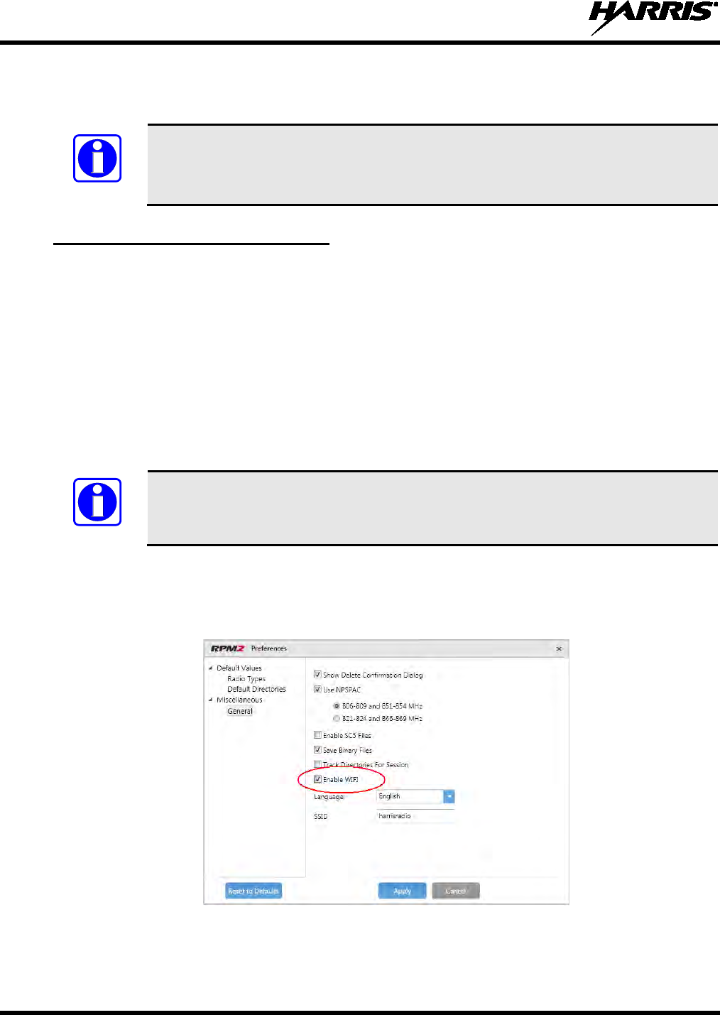
14221-1800-2000, Rev. D
98
APPENDIX A WI-FI PROGRAMMING
These instructions assume the user has a basic familiarity with Wi-Fi Networks, their
configurat
ion, and how to connect devices. If you are unfamiliar with the terms and/or
procedures mentioned in these instructions, please contact your IT department for help
before attempting to configure Wi-Fi programming.
A.1 NETWORK CONFIGURATION
• In order to program the XL-200P over Wi-Fi, you need to have a wireless network available. This
wireless network will be used by RPM2 and the radio for Wi-Fi functionality. RPM2 and the XL-
200P come with a default Wi-Fi configuration, but they can be customized to match an existing Wi-Fi
configuration.
• For default operation, setup a wireless network (access point) as follows:
SSID (or networking name) is set to the radio default of “harrisradios”
Password of “password”
Encryption type of either WPA or WPA2
• Ensure your wireless router supports mDNS/Multicast
In order for XL-200P radios to be discoverable on the Wi-Fi network, your wireless
router must be configured to allow mDNS/Multicast. This varies by router
manufacturer; refer to your router’s documentation for specific settings needed to enable
mDNS/Multicast.
A.2 RADIO/RPM CONFIGURATION
Ensure that Enable WIFI is enabled (checked) on the RPM 2 Preferences screen as shown in Figure
12-1. This is disabled (unchecked) by default.
Figure 12-1: Enable WIFI in RPM 2
For default operation using the network as described in Section A.1, no other configuration of the radio or
RPM is required.
NOTE
NOTE
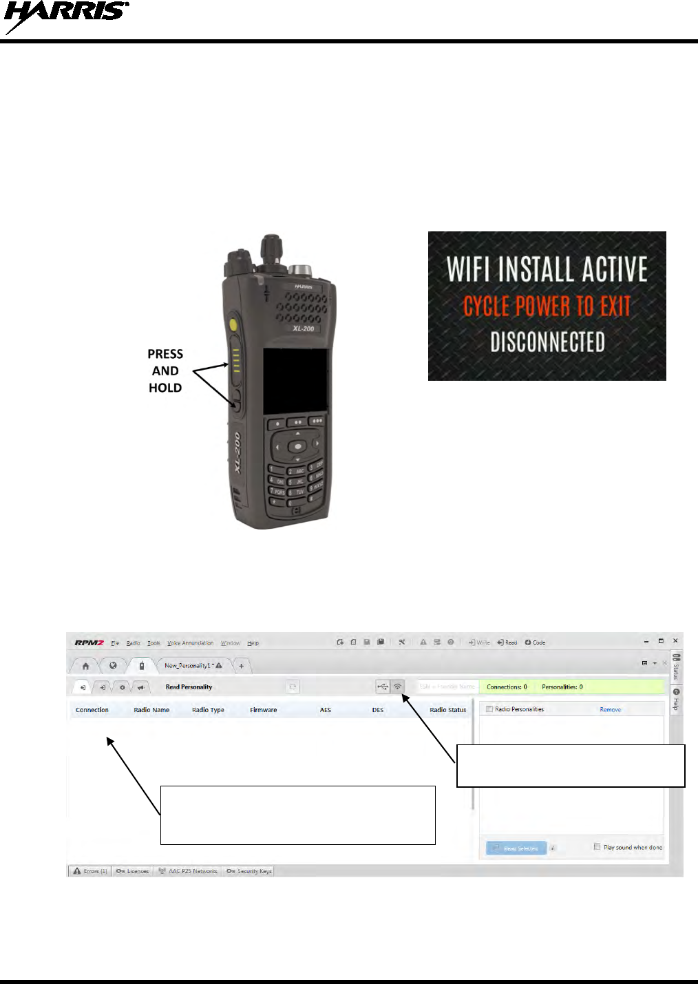
14221-1800-2000, Rev. D
99
A.3 PC CONFIGURATION
Configure the PC to connect to the same Wireless network as the radio. For Windows 7, this can be done
through the Network and Sharing Center.
A.4 CONNECTION
1. For default operation, power on radio while pressing and holding the bottom side and PTT buttons.
This places the radio into Wi-Fi programming mode. A screen appears on the front panel indicating
the radio is in Wi-Fi programming mode.
Figure 12-2: Enable Wi-Fi on XL-200P
2. Start RPM2.
3. Select the Connection tab (the one with the radio icon) and click the Wi-Fi connection button as
shown below. You should see any radios that are in Wi-Fi mode appear.
Radios should start to appear in this area once
RPM2 and the radio(s) are on the same
network.
Make sure this button is selected to
get into Wi-Fi discovery mode.
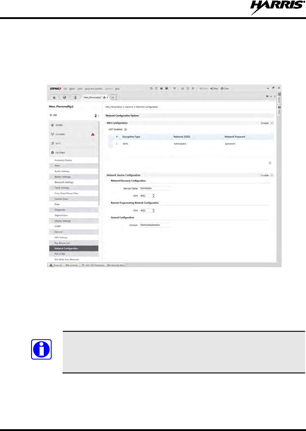
14221-1800-2000, Rev. D
100
A.5 PERSONAL/CUSTOM NETWORK CONFIGURATION
1. In order to use a wireless network with parameters that are different from the default configuration
above, some configuration of RPM2 and the radio is required. In RPM2, create a new personality or
open a personality previously created for the radio that you wish to program over Wi-Fi.
2. Navigate to the Network Configuration screen as shown in Figure 12-3. The default parameters as
noted in Section A.4 should be shown.
Figure 12-3: RPM2 Network Configuration Screen
3. Change the parameters as needed to match the configuration of the network you are trying to use for
Wi-Fi programming.
4. Reprogram the radio with this personality over USB and activate it.
5. You should now be able to connect to this radio over Wi-Fi following the procedure as outlined in
Section A.4.
In order to connect over Wi-Fi, the currently active personality MUST have the correct
Wi-Fi parameters. Therefore, care must be taken that all personalities on a given radio
have the correct Wi-F
i parameters for the desired network. Otherwise, activation of
another personality on the radio will result in the inability to establish a Wi-Fi
connection.
NOTE

14221-1800-2000, Rev. D
101
This page intentionally left blank.


Product Safety Manual
14221-1800-2010
Rev. B, Feb/16
This booklet contains important
safety information regarding specific
absorption rate (SAR) and RF
exposure limits included in United
States
and international standards.
Read the information in this booklet
before operating your radio.
XL-200P Series
Portable Radios

2 14221-1800-2010, Rev. B
REV
DATE
DESCRIPTION
-
Aug/15
Initial release.
A
Nov/15
Added CE information.
B Feb/16
Updated DoC and added EU regulatory
approval info and EU RF exposure info.
Updated Table 1-1 and Tableau 2-1.
ACKNOWLEDGEMENTS
The software contained in this device is copyrighted by
Harris Corporation. Unpublished rights are reserved under
the copyright laws of the United States.
This device is made under license under one or more of the
following US patents: 4,590,473; 4,636,791; 5,148,482;
5,185,796; 5,271,017; 5,377,229; 4,716,407; 4,972,460;
5,502,767; 5,146,497; 5,164,986; 5,185,795; 5,226,084;
5,247,579; 5,491,772; 5,517,511; 5,630,011; 5,649,050;
5,701,390; 5,715,365; 5,754,974; 5,826,222; 5,870,405;
6,161,089; and 6,199,037 B1. DVSI claims certain rights,
including patent rights under aforementioned U.S. patents,
and under other U.S. and foreign patents and patents
pending. Any use of this software or technology requires a
separate written license from DVSI.
CREDITS
Harris and assuredcommunications are registered
trademarks of Harris Corporation.
RBRC and 1-800-8-BATTERY are registered trademarks of
Rechargeable Battery Recycling Corporation.
All other product and brand names are trademarks,
registered trademarks, or service marks of their respective
holders. NOTICE
The material contained herein is subject to U.S. export
approval. No export or re-export is permitted without
written approval from the U.S. Government. Rated: EAR99;
in accordance with U.S. Dept. of Commerce regulations
15CFR774, Export Administration Regulations.
Information and descriptions contained herein are the
property of Harris Corporation. Such information and
descriptions may not be copied or reproduced by any means,
or disseminated or distributed without the express prior
written permission of Harris Corporation, PSPC Division,
221 Jefferson Ridge Parkway, Lynchburg, VA 24501.
This product conforms to the European Union
WEEE Directive 2012/19/EU.
Do not dispose of
this product in a public landfill.
This product
should be taken to a recycling center at the end of
its life.
14221-1800-2010, Rev. B 3
The voice coding technology embodied in this product is
protected by intellectual property rights including patent
rights, copyrights, and trade secrets of Digital Voice
Systems, Inc. The user of this technology is explicitly
prohibited from attempting to decompile, reverse engineer,
or disassemble the Object Code, or in any other way convert
the Object Code into human-readable form.
Repairs to this equipment should be made only by an
authorized service technician or facility designated by the
supplier. Any repairs, alterations, or substitution of
recommended parts made by the user to this equipment not
approved by the manufacturer could void the user’s
authority to operate the equipment in addition to the
manufacturer’s warranty.
This manual is published by Harris Corporation, without
any warranty. Improvements and changes to this manual
necessitated by typographical errors, inaccuracies of current
information, or improvements to programs and/or
equipment, may be made by Harris Corporation, at any
time and without notice. Such changes will be incorporated
into new editions of this manual. No part of this manual
may be reproduced or transmitted in any form or by any
means, electronic or mechanical, including photocopying
and recording, for any purpose, without the express written
permission of Harris Corporation.
Copyright © 2016 Harris Corporation.
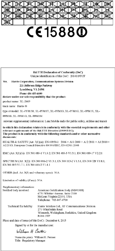
4 14221-1800-2010, Rev. B
This device is a RF transceiver intended for land mobile
radio applications. The device may have use restrictions,
which require that the national authority be contacted for
any system licensing requirements, frequency use, allowable
power level, etc.

14221-1800-2010, Rev. B 5
Česky
[Czech]
Harris Corporation tímto prohlašuje, že
tento XL-200P je ve shodě se
základními požadavky a dalšími
příslušnými ustanoveními směrnice
1999/5/ES.
Dansk
[Danish]
Undertegnede Harris Corporation
erklærer herved, at følgende udstyr
XL-
200P overholder de væsentlige
krav og øvrige relevante krav i direktiv
1999/5/EF.
Deutsch
[German]
Hiermit erklärt Harris Corporation,
dass sich das Gerät XL-200P in
Übereinstimmung mit den
grundlegenden Anforderungen und
den übrigen einschlägigen
Bestimmungen der Richtlinie
1999/5/EG befindet.
Eesti
[Estonian]
Käesolevaga kinnitab Harris
Corporation seadme XL-200P
vastavust direktiivi 1999/5/EÜ
põhinõuetele ja nimetatud direktiivist
tulenevatele teistele asjakohastele
sätetele.
English
Hereby, Harris Corporation, declares
that this XL-200P is in compliance with
the essential requirements and other
relevant provisions of Directive
1999/5/EC.
Español
[Spanish]
Por medio de la presente Harris
Corporation declara que el XL-200P
cumple con los requisitos esenciales y
cualesquiera otras disposiciones
aplicables o exigibles de la Directiva
1999/5/CE.
Ελληνική
[Greek]
ΜΕ ΤΗΝ ΠΑΡΟΥΣΑ Harris
Corporation ΔΗΛΩΝΕΙ ΟΤΙ XL-200P
ΣΥΜΜΟΡΦΩΝΕΤΑΙ ΠΡΟΣ ΤΙΣ
ΟΥΣΙΩΔΕΙΣ ΑΠΑΙΤΗΣΕΙΣ ΚΑΙ ΤΙΣ
ΛΟΙΠΕΣ ΣΧΕΤΙΚΕΣ ΔΙΑΤΑΞΕΙΣ ΤΗΣ
ΟΔΗΓΙΑΣ 1999/5/ΕΚ.
Français
[French]
Par la présente Harris Corporation
déclare que l'appareil XL-200P est
conforme aux exigences essentielles
et aux autres dispositions pertinentes
de la directive 1999/5/CE.
6 14221-1800-2010, Rev. B
Italiano
[Italian]
Con la presente Harris Corporation
dichiara che questo XL-200P è
conforme ai requisiti essenziali ed alle
altre disposizioni pertinenti stabilite
dalla direttiva 1999/5/CE.
Latviski
[Latvian]
Ar šo Harris Corporation deklarē, XG
25P UHF-L(378-470 MHz), 7/800
(764-870MHz) atbilst Direktīvas
1999/5/EK būtiskajām prasībām un
citiem ar to saistītajiem noteikumiem.
Lietuvių
[Lithuanian]
Šiuo Harris Corporation deklaruoja,
kad šis XL-200P atitinka esminius
reikalavimus ir kitas 1999/5/EB
Direktyvos nuostatas.
Nederlands
[Dutch]
Hierbij verklaart Harris Corporation dat
het toestel XL-
200P in
overeenstemming is met de essentiële
eisen en de andere relevante
bepalingen van richtlijn 1999/5/EG.
Malti
[Maltese]
Hawnhekk, Harris Corporation,
jiddikjara li dan XL-200P jikkonforma
mal-ħtiġijiet essenzjali u ma
provvedimenti oħrajn relevanti li hemm
fid-Dirrettiva 1999/5/EC.
Magyar
[Hungarian]
Alulírott, Harris Corporation
nyilatkozom, hogy a XL-200P megfelel
a vonatkozó alapvetõ
követelményeknek és az 1999/5/EC
irányelv egyéb elõírásainak.
Polski
[Polish]
Niniejszym Harris Corporation
oświadcza, że XL-200P jest zgodny z
zasadniczymi wymogami oraz
pozostałymi stosownymi
postanowieniami Dyrektywy
1999/5/EC.
Português
[Portuguese]
Harris Corporation declara que este
XL-200P
está conforme com os
requisitos essenciais e outras
disposições da Directiva 1999/5/CE.
Slovensko
[Slovenian]
Harris Corporation izjavlja, da je ta XL-
200P v skladu z bistvenimi zahtevami
in ostalimi relevantnimi določili
direktive 1999/5/ES.
Slovensky
[Slovak]
Harris Corporation týmto vyhlasuje, že
XL-200P spĺňa základné požiadavky a
všetky príslušné ustanovenia
Smernice 1999/5/ES.

14221-1800-2010, Rev. B 7
Suomi
[Finnish]
Harris Corporation vakuuttaa täten että
XL-200P tyyppinen laite on direktiivin
1999/5/EY oleellisten vaatimusten ja
sitä koskevien direktiivin muiden
ehtojen mukainen.
Svenska
[Swedish]
Härmed intygar Harris Corporation att
denna XL-200P
står I
överensstämmelse med de väsentliga
egenskapskrav och övriga relevanta
bestämmelser som framgår av direktiv
1999/5/EG.
Íslenska
[Icelandic]
Hér með lýsir Harris Corporation yfir
því að XL-200P
er í samræmi við
grunnkröfur og aðrar kröfur, sem
gerðar eru í tilskipun 1999/5/EC.
Norsk
[Norwegian]
Harris Corporation erklærer herved at
utstyret XL-200P er i samsvar med de
grunnleggende krav og øvrige
relevante krav i direktiv 1999/5/EF.

8 14221-1800-2010, Rev. B
TABLE OF CONTENTS Page
1. REGULATORY & SAFETY INFORMATION .. 9
1.1 SAFETY SYMBOL CONVENTIONS............ 9
1.2 SAFETY TRAINING INFORMATION ....... 10
1.3 REGULATORY APPROVALS .................... 13
1.4 OPERATING TIPS ....................................... 13
2. RENSEIGNEMENTS SUR LA
RÉGLEMENTATION ET SÉCURITÉ ............. 17
2.1 CONVENTIONS SUR LES SYMBOLES
DE SÉCURITÉ .............................................. 17
2.2 RENSEIGNEMENTS SUR LA
FORMATION SUR LA SÉCURITÉ ............. 18
2.3 INTERFÉRENCE DES
RADIOFRÉQUENCES ................................. 21
2.4 CONSEILS D’UTILISATION ...................... 22
3. OPTIONS AND ACCESSORIES ....................... 26
4. BATTERY PACKS .............................................. 27
4.1 CONDITIONING LITHIUM-ION
BATTERY PACKS ....................................... 28
4.2 STORING LI-ION BATTERY PACKS ........ 28
4.3 ADDITIONAL INFORMATION .................. 28
4.4 BATTERY DISPOSAL ................................. 28
5. TECHNICAL ASSISTANCE .............................. 30
6. WARRANTY ....................................................... 31
Harris Corporation, Public Safety and Professional
Communications (PSPC) Business continually evaluates its
technical publications for completeness, technical accuracy,
and organization. You can assist in this process by
submitting your comments and suggestions to the following:
Harris Corporation
PSPC Business
Technical Publications
221 Jefferson Ridge Parkway
Lynchburg, VA 24501
Or
Fax your comments to: 1-434-455-6851
Or
E-mail us at: PSPC_TechPubs@harris.com
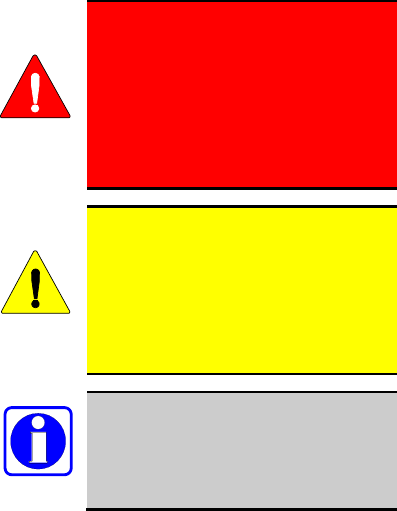
14221-1800-2010, Rev. B 9
1. REGULATORY & SAFETY
INFORMATION
1.1 SAFETY SYMBOL
CONVENTIONS
The following conventions are used to alert the user
to general safety precautions that must be observed
during all phases of operation, service, and repair of
this product. Failure to comply with these
precautions or with specific warnings elsewhere
violates safety standards of design, manufacture, and
intended use of the product. Harris assumes no
liability for the customer's failure to comply with
these standards.
The WARNING symbol calls
attention to a procedure, practice, or
the like, which, if not correctly
performed or adhered to, could
result in personal injury. Do not
proceed beyond a WARNING
symbol until the conditions identified
are fully understood or met.
The CAUTION symbol calls attention
to an operating procedure, practice, or
the like, which, if not performed
correctly or adhered to, could result in a
risk of danger, damage to the
equipment, or severely degrade the
equipment performance.
The NOTE symbol calls attention to
supplemental information, which may
improve system performance or clarify
a process or procedure.
WARNING
CAUTION
NOTE

10 14221-1800-2010, Rev. B
1.2 SAFETY TRAINING
INFORMATION
The Harris XL-200P portable radio
generates RF electromagnetic energy
during transmit mode. This radio is
designed for and classified as
“Occupational Use Only,” meaning it
must be used only during the course
of employment by individuals aware
of the hazards and the ways to
minimize such hazards. This radio is
NOT intended for use by the
“General Population” in an
uncontrolled environment.
The XL-200P portable radio has been tested and
complies with the FCC RF exposure limits for
“Occupational Use Only.” In addition, this radio
complies with the following Standards and
Guidelines with regard to RF energy and
electromagnetic energy levels and evaluation of such
levels for exposure to humans:
• FCC OET Bulletin 65 Edition 97-01
Supplement C, Evaluating Compliance with
FCC Guidelines for Human Exposure to Radio
Frequency Electromagnetic Fields.
• American National Standards Institute (C95.1 –
1992), IEEE Standard for Safety Levels with
Respect to Human Exposure to Radio Frequency
Electromagnetic Fields, 3 kHz to 300 GHz.
• American National Standards Institute (C95.3 –
1992), IEEE Recommended Practice for the
Measurement of Potentially Hazardous
Electromagnetic Fields – RF and Microwave.
• IC Standard RSS-102. Radio frequency
Exposure Compliance of Radio communication
Apparatus (All Frequency Bands).
• European Council Directive 89/391/EEC.
WARNING

14221-1800-2010, Rev. B 11
1.2.1 RF Exposure Guidelines
To ensure that exposure to RF
electromagnetic energy is within the
EU/AU/FCC/IC
allowable limits for
occupational use, always adhere to the
following guidelines:
• DO NOT operate the radio without a proper
antenna attached, as this may damage the radio
and may also cause the FCC RF exposure limits
to be exceeded. A proper antenna is the antenna
supplied with this radio by Harris or an antenna
specifically authorized by Harris for use with
this radio.
• DO NOT transmit for more than 50% of total
radio use time (“50% duty cycle”). Transmitting
more than 50% of the time can cause FCC RF
exposure compliance requirements to be
exceeded. The radio is transmitting when the
“TX” indicator appears in the display. The radio
will transmit by pressing the “PTT” (Push-To-
Talk) button.
• ALWAYS transmit using low power when
possible. In addition to conserving battery
charge, low power can reduce RF exposure.
• ALWAYS use Harris authorized accessories
(antennas, batteries, belt clips, speaker/mics,
etc). Use of unauthorized accessories may cause
the FCC Occupational/Controlled Exposure RF
compliance requirements to be exceeded. (Refer
to Table 1-1.)
• As noted in Table 1-1, ALWAYS keep the
housing of the transmitter AT LEAST 0.47
inches (1.2 cm) from the body and at least 0.98
inches (2.5 cm) from the face when transmitting
to ensure FCC RF exposure compliance
requirements are not exceeded. However, to
provide the best sound quality to the recipients
of your transmission, Harris recommends you
hold the microphone at least 5 cm (2 inches)
from mouth, and slightly off to one side.
• Refer to Standard EN 62311:2008.
CAUTION

12 14221-1800-2010, Rev. B
Table 1-1: RF Exposure Compliance Tested
Distances1
RADIO FREQUENCY
BAND
TESTED
DISTANCES
(worst case scenario)
Body2 Face
VHF
(136 - 174 MHz)
0.47 in
(1.2 cm) 0.98 in
(2.5 cm)
UHF
(378 - 522 MHz)
0.47 in
(1.2 cm) 0.98 in
(2.5 cm)
700/800 MHz
(768 - 776 MHz)
(798 - 806 MHz)
(806 - 824 MHz)
(851 - 870 MHz)
0.47 in
(1.2 cm) 0.98 in
(2.5 cm)
2400 MHz
(2412 - 2472 MHz)
0.47 in
(1.2 cm)
0.98 in
(2.5 cm)
5 GHz
(5.18 - 5.825 GHz)
0.47 in
(1.2 cm)
0.98 in
(2.5 cm)
The information in this section provides the
information needed to make the user aware of a RF
exposure, and what to do to assure that this radio
operates within the FCC RF exposure limits.
1.2.2 Electromagnetic
Interference/Compatibility
During transmissions, Harris radios generate RF
energy that can possibly cause interference with other
devices or systems. To avoid such interference, turn
off the radios in areas where signs are posted to do
so. DO NOT operate the transmitter in areas that are
sensitive to electromagnetic radiation such as
hospitals, aircraft, and blasting sites.
1 Minimum safe operating distances for the radio are
based on the Harmonized Standards and SAR
evaluation.
2 This is worst case based on the thinnest body mount
accessory (belt clip).

14221-1800-2010, Rev. B 13
1.3 REGULATORY APPROVALS
1.3.1 Part 15
This device complies with Part 15 of the FCC Rules.
Operation is subject to the following two conditions:
1. This device may not cause harmful interference,
and
2. This device must accept any interference
received, including interference that may cause
undesired operation.
1.3.2 Industry Canada
This device complies with Industry Canada license-
exempt RSS standard(s). Operation is subject to the
following two conditions: (1) this device may not
cause interference, and (2) this device must accept
any interference, including interference that may
cause undesired operation of the device.
1.4 OPERATING TIPS
Antenna location and condition are important when
operating a portable radio. Operating the radio in low
lying areas or terrain, under power lines or bridges,
inside of a vehicle or in a metal framed building can
severely reduce the range of the unit. Mountains can
also reduce the range of the unit.
In areas where transmission or reception is poor,
some improvement may be obtained by ensuring the
antenna is vertical. Moving a few yards in another
direction or moving to a higher elevation may also
improve communications. Vehicular operation can be
aided with the use of an externally mounted antenna.
Battery condition is another important factor in the
trouble free operation of a portable radio. Always
properly charge the batteries.
1.4.1 Efficient Radio Operation
Keep the antenna in a vertical position when
receiving or transmitting a message.

14 14221-1800-2010, Rev. B
Do NOT hold onto the antenna when
the radio is powered on.
1.4.1.1 Antenna Care and
Replacement
Always keep the antenna at least
0..47 inches (1.2 cm) away from the
body and 0.98 inches (2.5 cm) from
the face when transmitting to ensure
FCC RF exposure compliance
requirements are not exceeded.
Do not use the portable radio with a
damaged or missing antenna. A
minor burn may result if skin comes
into contact with a damaged antenna.
Replace a damaged antenna
immediately. Operating a portable
radio with the antenna missing could
cause personal injury, damage the
radio, and may violate FCC
regulations.
Use only the supplied or approved
antenna. Unauthorized antennas,
modifications, or attachments could
cause damage to the radio unit and may
violate FCC regulations.
WARNING
WARNING
WARNING
CAUTION

14221-1800-2010, Rev. B 15
1.4.1.2 Electronic Devices
RF energy from portable radios may
affect some electronic equipment. Most
modern electronic equipment in cars,
hospitals, homes, etc., are shielded from
RF energy. However, in areas in which
you are instructed to turn off two-way
radio equipment, always observe the
rules. If in doubt, turn it off!
1.4.1.3 Aircraft
Always turn
off a portable radio
before boarding any aircraft!
• Use it on the ground only with
crew permission.
• DO NOT use while in-flight!!
1.4.1.4 Electric Blasting Caps
To prevent accidental detonation of
electric blasting caps, DO NOT use
two-way radios within 1000 fee
t of
blasting operations. Always obey the
"Turn Off Two-Way Radios" signs
posted where electric blasting caps
are being used. (OSHA Standard:
1926.900)
CAUTION
WARNING
WARNING

16 14221-1800-2010, Rev. B
1.4.1.5 Potentially Explosive
Atmospheres
Areas with potentially explosive
atmospheres are often, but not
always, clearly marked. These may
be fuelling areas, such as gas stations,
fuel or chemical transfer or storage
facilities, and areas where the air
contains chemicals or particles, such
as grain, dust, or metal powders.
Sparks in such areas could cause an
explosion or fire resulting in bodily
injury or even death.
Turn OFF two-way radios when in
any area with a potentially explosive
atmosphere. It is rare, but not
impossible that a radio or its
accessories could generate sparks.
DO NOT remove, install, or charge
batteries in potentially explosive
atmosphere areas.
Sparks in such areas could cause an
explosion or fire resulting in bodily
injury or even death.
WARNING
WARNING

14221-1800-2010, Rev. B 17
2. RENSEIGNEMENTS SUR LA
RÉGLEMENTATION ET SÉCURITÉ
2.1 CONVENTIONS SUR LES
SYMBOLES DE SÉCURITÉ
Les conventions suivantes sont utilisées dans le
présent manuel pour avertir l’utilisateur des
précautions générales de sécurité qui doivent être
observées pendant toutes les phases d’opération,
d’entretien et de réparation de ce produit. Le non-
respect de ces précautions ou d’avertissements
précisés ailleurs enfreint les normes de sécurité de la
conception, de la fabrication et de l’utilisation prévue
du produit. Harris n’assume aucune responsabilité
pour le non-respect de ces normes par le client.
MISE EN GARDE
Le symbole MISE EN GARDE
at
tire l’attention sur une
procédure ou une pratique qui, si
elle n’est pas correctement
effectuée ou observée, pourrait
entraîner une blessure
personnelle.
Ne pas poursuivre
au-delà d’un symbole de MISE
EN GARDE avant que les
conditions identifiées soient
c
omplètement comprises ou
satisfaites.
AVERTISSEMENT
Le symbole AVERTISSEMENT
attire l’attention sur une procédure
ou une pratique opérationnelle qui,
si elle n’est pas correctement
effectuée ou observée, pourrait
entraîner un bris d’équipement ou
une importante baisse de
rendement de l’équipement.

18 14221-1800-2010, Rev. B
REMARQUE
Le symbole REMARQUE attire
l’attention sur des renseignements
supplémentaires qui peuvent
améliorer le rendement du système
ou clarifier un processus ou une
procédure.
2.2 RENSEIGNEMENTS SUR LA
FORMATION SUR LA SÉCURITÉ
MISE EN GARDE
La radio portative Harris XL-
200P produit de l’énergie
électromagnétique des RF
lorsqu’en mode de transmission.
Cette radio est conçue et classée
pour une « Utilisation
professionnelle seulement
», ce
qui signifie qu’elle ne doit être
utilisée que dans le cadre d’un
emploi par des individus
conscients des risques et des
moyens de limiter ceux-ci. Cette
radio N’EST PAS conçue pour
une utilisation par la
« Population générale » dans un
environnement non contrôlé.
La radio portative XL-200P a été testée et est
conforme aux limites d’exposition aux RF de la FCC
pour une « Utilisation professionnelle seulement ».
De plus, cette radio Harris est conforme aux normes
et directives suivantes quant à l’énergie des RF et aux
niveaux d’énergie électromagnétique, ainsi qu’à
l’évaluation de ces niveaux pour l’exposition aux
humains :
• Bulletin 65 du OET de la FCC, édition 97-01,
supplément C, portant sur l’évaluation de la
conformité aux directives de la FCC quant à
l’exposition humaine aux champs
électromagnétiques des radiofréquences.

14221-1800-2010, Rev. B 19
• American National Standards Institute (C95.1 –
1992), norme de l’IEEE sur les niveaux
sécuritaires d’exposition humaine aux champs
électromagnétiques des radiofréquences, 3 kHz
à 300 GHz.
• American National Standards Institute (C95.3 –
1992), pratique recommandée par l’IEEE pour la
mesure des champs électromagnétiques
potentiellement dangereux – RF et micro-ondes.
2.2.1 Directives sur l’exposition aux
RF
AVERTISSEMENT
Pour s’assurer que l’
exposition à
l’
énergie électromagnétique des RF
se situe dans les limites acceptables
de la FCC pour l’utilisation
professionnelle, respectez toujours les
directives suivantes :
• N’utilisez PAS la radio sans qu’une antenne
appropriée y soit connectée, car ceci peut
endommager la radio et également causer un
dépassement des limites d’exposition aux RF de
la FCC. Une antenne appropriée est celle fournie
par Harris avec cette radio, ou une antenne
spécifiquement autorisée par Harris pour être
utilisée avec cette radio.
• Ne transmettez PAS pendant plus de 50 % de la
durée d’utilisation totale de la radio (« cycle de
service de 50 % »). La transmission pendant
plus de 50 % du temps peut causer un
dépassement des exigences de conformité de la
FCC en matière d’exposition aux RF. La radio
transmet lorsque l’indicateur « TX » apparaît sur
l’affichage. La radio transmet lorsqu’on appuie
sur le bouton « PTT » (bouton de microphone).
• Transmettez TOUJOURS en basse puissance
lorsque possible. En plus de préserver la charge

20 14221-1800-2010, Rev. B
de la pile, une faible puissance réduit
l’exposition aux RF.
• Utilisez TOUJOURS des accessoires autorisés
Harris (antennes, piles, pinces de ceinture, haut-
parleurs/micros, etc.). L’utilisation d’accessoires
non autorisés peut entraîner un dépassement des
exigences de conformité pour une exposition
aux RF professionnelle ou contrôlée de la FCC.
(Reportez-vous à Tableau 2-1.)
• Tel qu’indiqué dans Tableau 2-1, conservez
TOUJOURS l’appareil et son antenne à AU
MOINS 1,2 cm (0,47 po) du corps, et à au
moins 2,5 cm (0,98 po) du visage pendant la
transmission, pour vous assurer de ne pas
dépasser les exigences de conformité de la FCC
en matière d’exposition aux RF. Cependant,
pour offrir la meilleure qualité sonore aux
auditeurs de votre transmission, Harris
recommande de tenir le microphone à au moins
5 cm (2 po) de votre bouche et légèrement
déplacé sur un côté.
Tableau 2-1 : Distances de test de conformité des
expositions aux RF
RADIOFRÉQUENCES
DISTANCES TESTÉES
(pire des scénarios)
Corps3
Visage
VHF
(136 - 174 MHz)
1,2 cm 2,5 cm
UHF
(378 - 522 MHz)
1,2 cm 2,5 cm
700/800 MHz
(768 - 776 MHz)
(798 - 806 MHz)
(806 - 824 MHz)
(851 - 870 MHz)
1,2 cm 2,5 cm
2400 MHz
(2412 - 2472 MHz)
1,2 cm 2,5 cm
3 Ce est le pire des cas basée sur le corps plus mince
monter accessoire (clip ceinture).

14221-1800-2010, Rev. B 21
RADIOFRÉQUENCES
DISTANCES TESTÉES
(pire des scénarios)
Corps3
Visage
5 GHz
(5.18 - 5.825 GHz)
1,2 cm 2,5 cm
Dans cette section figurent les renseignements
nécessaires pour sensibiliser l’utilisateur à
l’exposition aux RF et sur ce qu’il faut faire pour
s’assurer que cette radio fonctionne dans les limites
d’exposition aux RF de la FCC.
2.2.2 Interférence/Compatibilité
Électromagnétique
Pendant les transmissions, cette radio Harris produit
de l’énergie des RF qui peut causer de l’interférence
avec d’autres appareils ou systèmes. Pour éviter de
telles interférences, fermez la radio dans les zones où
il est indiqué de le faire. N’utilisez PAS le
transmetteur dans des zones sensibles aux radiations
électromagnétiques, comme les hôpitaux, les avions
et les sites de détonation.
2.3 INTERFÉRENCE DES
RADIOFRÉQUENCES
2.3.1 Partie 15 de la FCC
Cet appareil est conforme à la Partie 15 de la
réglementation de la FCC. Le fonctionnement est
soumis aux deux conditions suivantes :
1. Cet appareil ne doit pas causer une interférence
nuisible; et
2. Cet appareil doit accepter toute interférence
reçue, y compris une interférence qui peut
causer un fonctionnement non souhaité.
2.3.2 Industrie Canada
Le présent appareil est conforme aux CNR d'Industrie
Canada applicables aux appareils radio exempts de
licence. L'exploitation est autorisée aux deux
conditions suivantes : (1) l'appareil ne doit pas
produire de brouillage, et (2) l'utilisateur de l'appareil

22 14221-1800-2010, Rev. B
doit accepter tout brouillage radioélectrique subi,
même si le brouillage est susceptible d'en
compromettre le fonctionnement.
2.4 CONSEILS D’UTILISATION
L’emplacement et l’état de l’antenne sont importants
pour l’utilisation d’une radio portative. L’utilisation
de la radio dans des zones de faible élévation, sous
des lignes électriques ou des ponts, à l’intérieur d’un
véhicule ou dans un immeuble à ossature métallique,
peut réduire la portée de l’appareil de manière
considérable. Les montagnes peuvent également
réduire la portée de l’unité.
Dans les zones où la transmission ou la réception est
insatisfaisante, certaines améliorations peuvent être
obtenues en s’assurant que l’antenne est verticale. Se
déplacer de quelques mètres dans une autre direction
ou à un emplacement plus élevé peut également
améliorer les communications. L’utilisation d’une
antenne fixée à l’extérieur peut faciliter le
fonctionnement dans un véhicule.
L’état de la pile est un autre facteur important d’une
utilisation sans tracas d’une radio portative. Chargez
toujours correctement la pile.
2.4.1 Utilisation Efficace de la Radio
Gardez l’antenne dans une position verticale pendant
la réception ou la transmission d’un message.
MISE EN GARDE
Ne tenez PAS l’antenne lorsque
la radio est allumée!

14221-1800-2010, Rev. B 23
2.4.1.1 Entretien et Remplacement
de l’antenne
MISE EN GARDE
C
onservez TOUJOURS
l’appareil et son antenne à au
moins 1,5 cm (0,59 po) du corps,
et à au moins 2,5 cm (1,0 po) du
visage pendant la transmission,
pour vous assurer de ne pas
dépasser les exigences de
conformité de la FCC en matière
d’exposition aux RF.
MISE EN GARDE
N’utilisez pas la radio portative
si son antenne est endommagée
ou absente. Une brûlure légère
peut se produire au contact
d’une antenne endommagée avec
la peau. Remplacez
immédiatement une antenne
endommagée. L’utilisation d’une
radio portative alors que
l’antenne est absente peut causer
des blessures, endommager la
radio et pourrait enfreindre la
réglementation de la FCC.
AVERTISSEMENT
Utilisez seulement l’antenne fournie
ou une antenne approuvée. Des
antennes non autorisées, des
modifications ou des ajouts à une
antenne peuvent endommager la
radio et enfreindre la réglementation
de la FCC.

24 14221-1800-2010, Rev. B
2.4.1.2 Appareils Électroniques
AVERTISSEMENT
L’énergie des RF provenant de radios
portatives peut affecter certains
appareils électroniques. La majorité
de l’
équipement électronique
moderne dans les voitures, les
hôpitaux, les maisons, etc. est blindé
contre l’énergie des RF. Cependant,
dans les zones où l’on vous demande
de fermer l’
équipement de radio
bidirectionnelle, respectez toujours
les règles. En cas de doute, éteignez-
le!
2.4.1.3 Avion
MISE EN GARDE
• Éteignez toujours une radio
portative avant
d’embarquer à bord d’un
avion!
• Ne l’utilisez au sol qu’avec
la permission de l’équipage.
• NE l’utilisez PAS durant le
vol!

14221-1800-2010, Rev. B 25
2.4.1.4 Détonateurs électriques
MISE EN GARDE
Pour prévenir la détonation
accidentelle des détonateurs
électriques, n’
utilisez PAS de
radios bidirectionnelles à moins
de 305 m (1 000
pi) des
opérations de détonation.
Respectez toujours les
indications « Éteindre les radios
bidirectionnelles
» situées là où
des détonateurs électriques sont
utilisés. (Norme OSHA :
1926.900)

26 14221-1800-2010, Rev. B
2.4.1.5 Atmosphère Potentiellement
Explosive
MISE EN GARDE
Les zones ayant une atmosphère
potentiellement explosive sont
souvent, mais pas toujours,
identifiées clairement comme
telles. Il peut s’
agir de zones
d’
alimentation en carburant,
comme les postes d’essence, les
installations de stockage ou de
transfert de carburant ou de
produits chimiques, ainsi que les
zones dont l’
air contient des
produits chimiques ou des
particules, comme des grains, de
la poussière ou des poudres
métalliques.
Des étincelles dans de telles zones
peuvent provoquer une explosion
ou un incendie, causant ainsi des
blessures ou même la mort.
Éteignez les radios
bidirectionnelles dans toute zone
ayant une atmosphère
potentiellement explosive. Il est
rare, mais pas impossible qu’une
radio ou ses accessoires
produisent des étincelles.
3. OPTIONS AND ACCESSORIES
A complete list of Options and Accessories approved
for use with the XL-200P portable radio can be found
online in the Operator’s Manual 14221-1800-2000 at
www.pspc.harris.com. Also reference the Products
and Services Catalog for all available options and
accessories, including those items that do not
adversely affect the RF energy exposure.

14221-1800-2010, Rev. B 27
Always
use Harris authorized
accessories (antennas, batteries, belt
clips, speaker/mics, etc). Use of
unauthorized accessories may cause
the FCC Occupational/Controlled
Exposure RF compliance
requirements to be exceeded.
Always
use the correct options and
accessories (battery, antenna,
speaker/mic, etc.) for the radio. See
Operator Manual 14221-1800-2000,
available online at
http://pspc.harris.com/Products/Portable/
XL200P.aspx, for the list of accessories.
4. BATTERY PACKS
The XL-200P series portable radios use rechargeable,
recyclable Lithium-Ion (Li-Ion) battery packs. Please
follow the directions below to maximize the useful
life of each type of battery pack.
Do not disassemble or modify
Lithium battery packs. The Lithium
battery packs are equipped with
built-
in safety and protection
features. Should these features be
disabled or tampered with in any
way, the battery pack can leak
electrolyte, overheat, emi
t smoke,
burst, and/or ignite.
If the battery pack is ruptured or is
leaking electrolyte that results in
skin or eye contact with the
electrolyte, immediately flush the
affected area with water. If the
battery electrolyte gets in the eyes,
flush with water for 15 minutes and
consult a physician immediately.
WARNING
CAUTION
WARNING
WARNING

28 14221-1800-2010, Rev. B
Always use Harris authorized chargers
and conditioners. Use of unauthorized
chargers and conditioners may void the
warranty.
4.1 CONDITIONING LITHIUM-ION
BATTERY PACKS
Li-Ion battery packs do not suffer from memory
effect and therefore do not require conditioning.
4.2 STORING LI-ION BATTERY
PACKS
If a battery pack is expected to be idle for a month or
more, it should be properly prepared. Li-Ion battery
packs should not be stored fully charged. Before
storing the battery pack, discharge it to 40% capacity.
If the battery is not discharged prior to storage, its
overall capacity may be reduced. Although all
battery packs experience some capacity loss during
storage, the shelf life for Li-Ion battery packs is about
3 months. However, note that any capacity drop
which occurs during storage is permanent and cannot
be reversed. Li-Ion battery packs should be
purchased and used immediately. They should not be
stock-piled without a rotating stock plan.
4.3 ADDITIONAL INFORMATION
For more information regarding the proper care of
portable radio battery packs or establishing a battery
maintenance program, refer to ECR-7367 which may
be ordered by calling toll free 1-800-368-3277
(international - 1-434-455-6403) or via
https://premier.pspc.harris.com/infocenter/.
4.4 BATTERY DISPOSAL
In no instance should a battery pack be
incinerated. Disposing of a battery
pack by burning will cause an
explosion.
CAUTION
CAUTION

14221-1800-2010, Rev. B 29
RECHARGEABLE BATTERY
PACK DISPOSAL – The product
you have purchased contains a
rechargeable battery pack
. The
battery pack is recyclable. At the
end of its useful life, under various
state and local laws, it may be
illegal to dispose of this battery
pack
into the municipal waste
stream. Check with your local
solid waste officials for details in
your area for recycling options or
proper disposal. Canadian and
U.S. users may call Toll Free 1-
800-8-BATTERY® for information
and/or procedures for returning
rechargeable batteries in your
locality.

30 14221-1800-2010, Rev. B
5. TECHNICAL ASSISTANCE
The Technical Assistance Center's (TAC’s) resources
are available to help with overall system operation,
maintenance, upgrades and product support. TAC is
your point of contact when answers are needed to
technical questions.
Product specialists, with detailed knowledge of
product operation, maintenance, and repair, provide
technical support via a toll-free (in North America)
telephone number. Support is also available through
mail, fax and e-mail.
For more information about technical assistance
services, contact your sales representative, or call the
Technical Assistance Center directly at:
North America: 1-800-528-7711
International: 1-434-385-2400
Fax: 1-434-455-6712
E-mail: PSPC_tac@harris.com

14221-1800-2010, Rev. B 31
6. WARRANTY
If any part of the system equipment is damaged on
arrival, contact the shipper to conduct an inspection
and prepare a damage report. Save the shipping
container and all packing materials until the
inspection and the damage report are completed. In
addition, contact the Customer Care center to make
arrangements for replacement equipment. Do not
return any part of the shipment until you receive
detailed instructions from a Harris representative.
North America:
Phone Number: 1-800-368-3277
Fax Number: 1-321-409-4393
E-mail: PSPC_CustomerFocus@harris.com
International:
Phone Number: 1-434-455-6403
Fax Number: 1-321-409-4394
E-mail:
PSPC_InternationalCustomerFocus@harris.com
Please register this product within 10 days of
purchase. Registration validates the warranty
coverage, and enables Harris to contact you in case of
any safety notifications issued for this product.
Registration can be made on-line at the Customer
Care center webpage:
http://www.pspc.harris.com/Service/Customerservice
.aspx.
While on the webpage, please review the applicable
battery and/or product warranty literature.