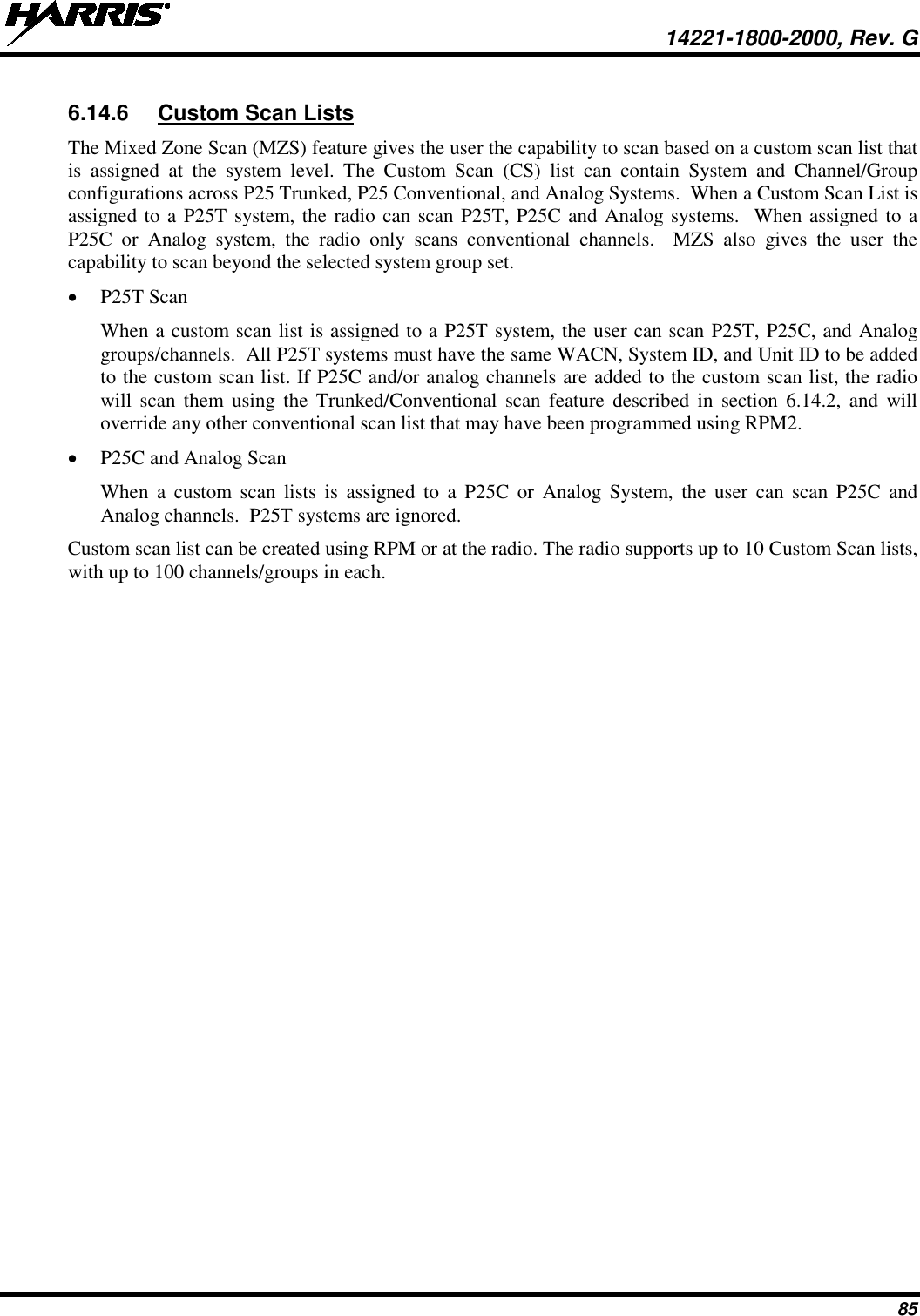
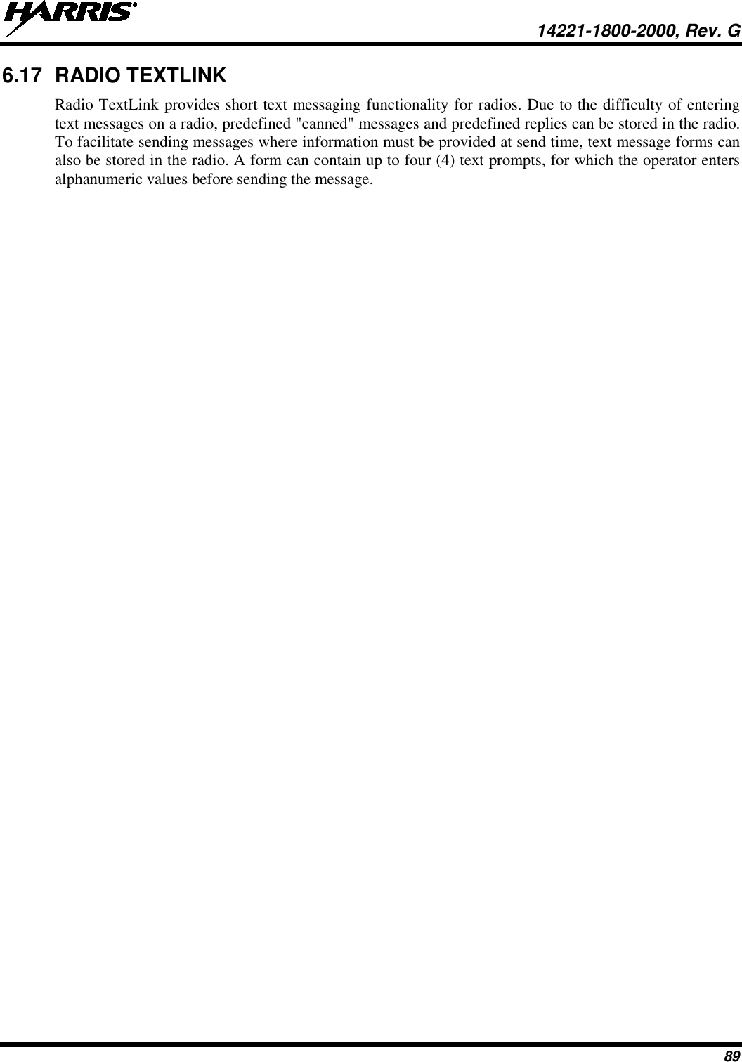
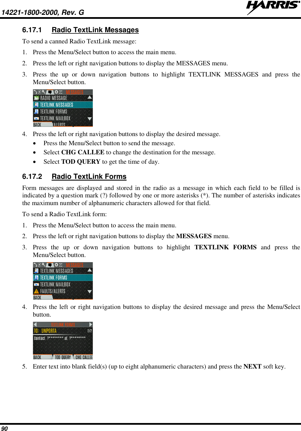
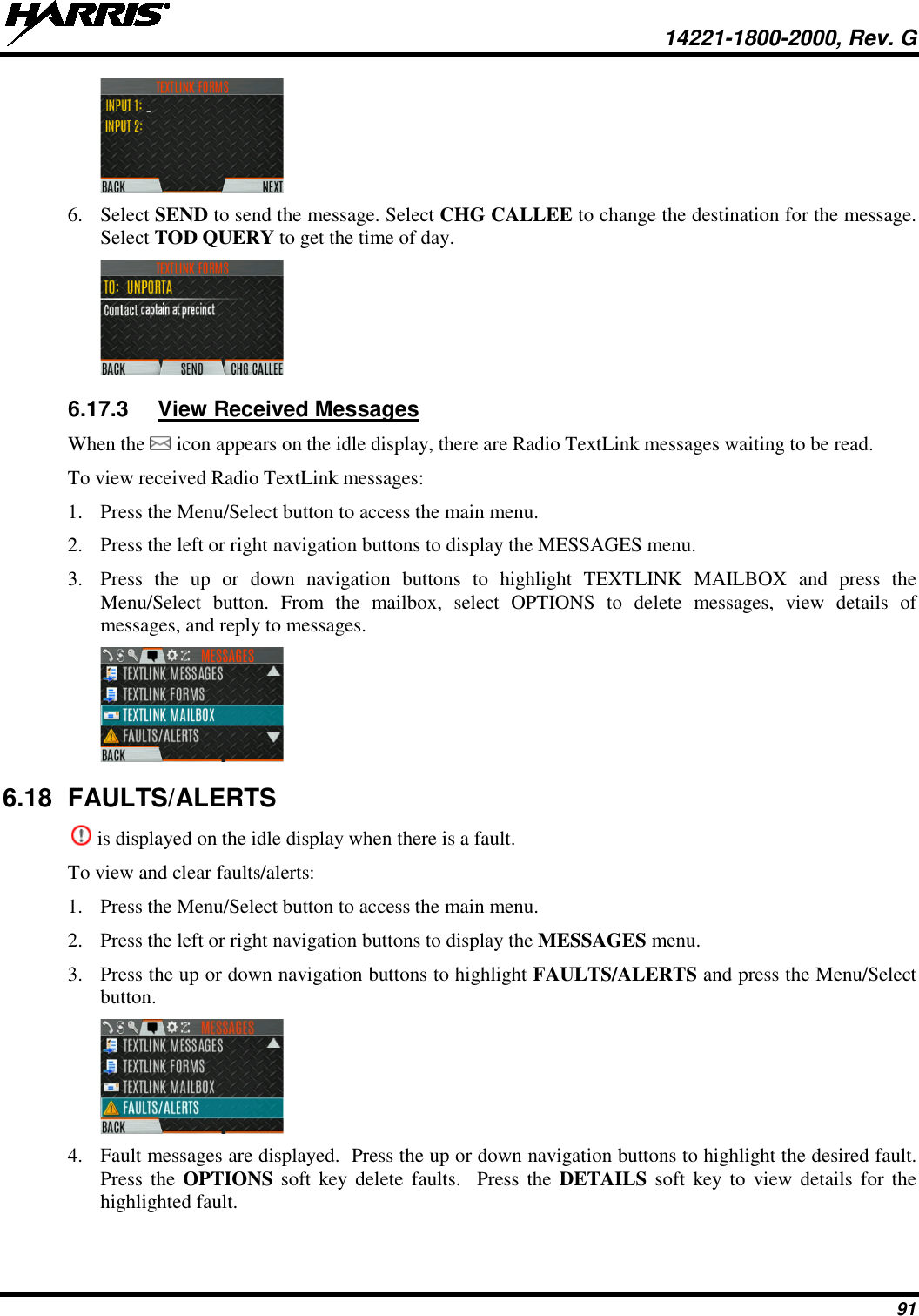
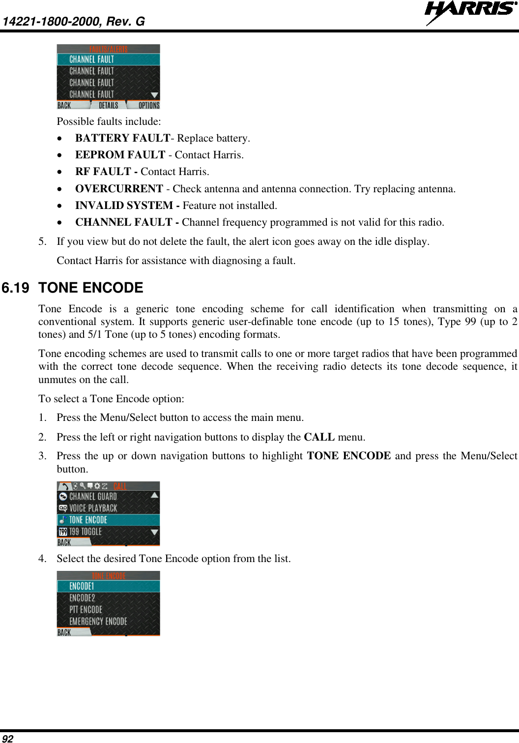
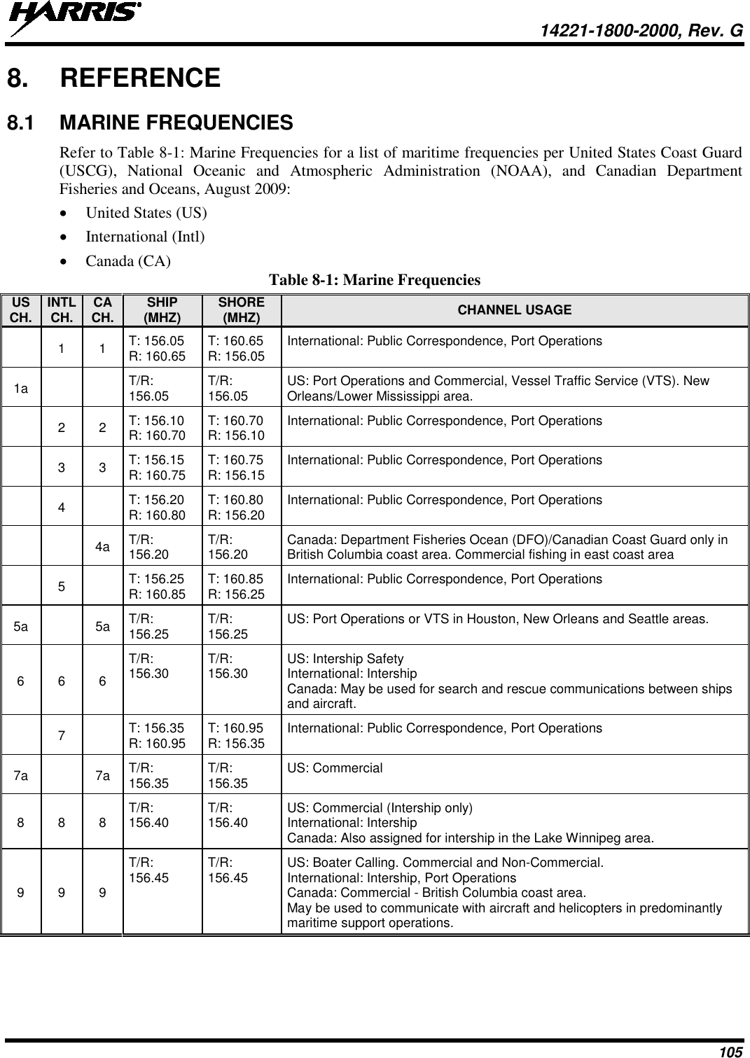
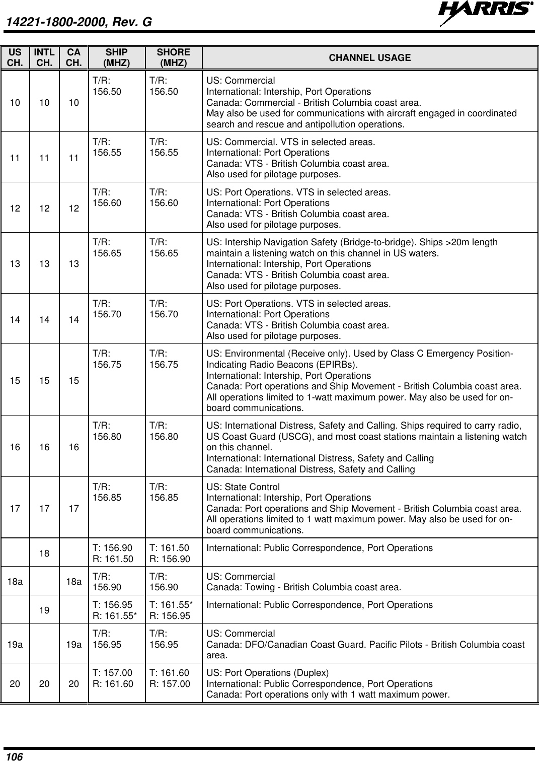
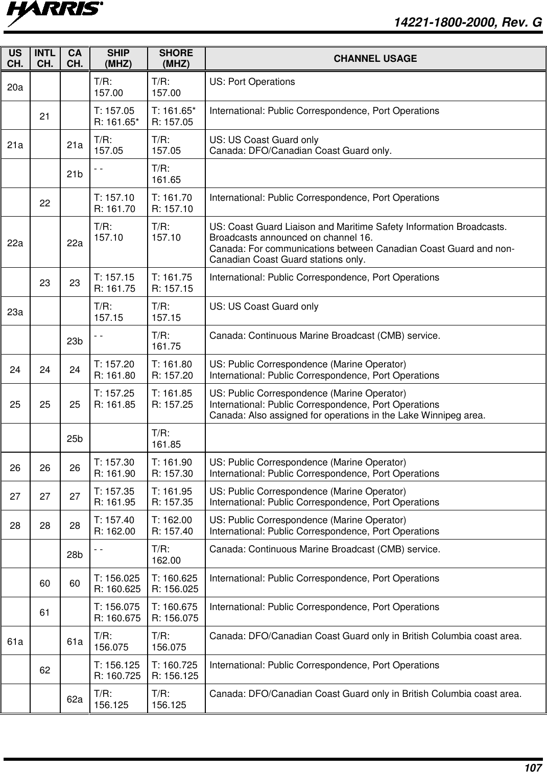
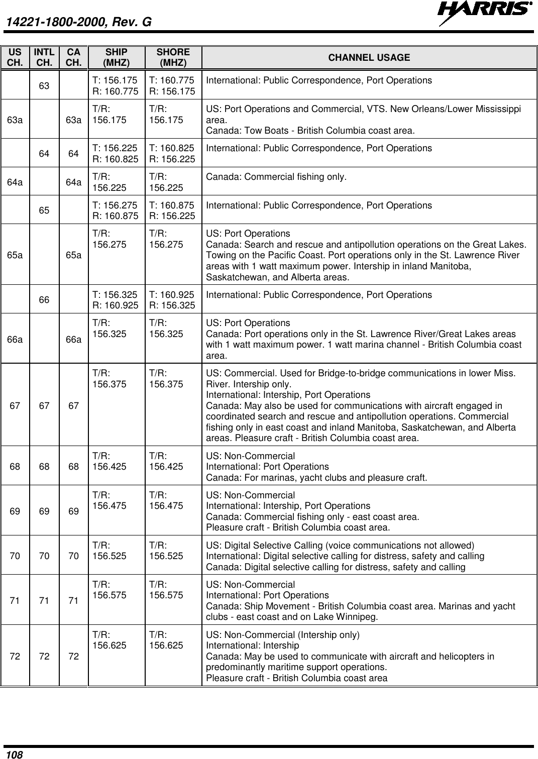
HARRIS TR-0154-E XL-185P, 7/800 MHz, Portable Land Mobile Radio, C1D1, Rebanded User Manual 2
HARRIS CORPORATION XL-185P, 7/800 MHz, Portable Land Mobile Radio, C1D1, Rebanded 2
HARRIS >
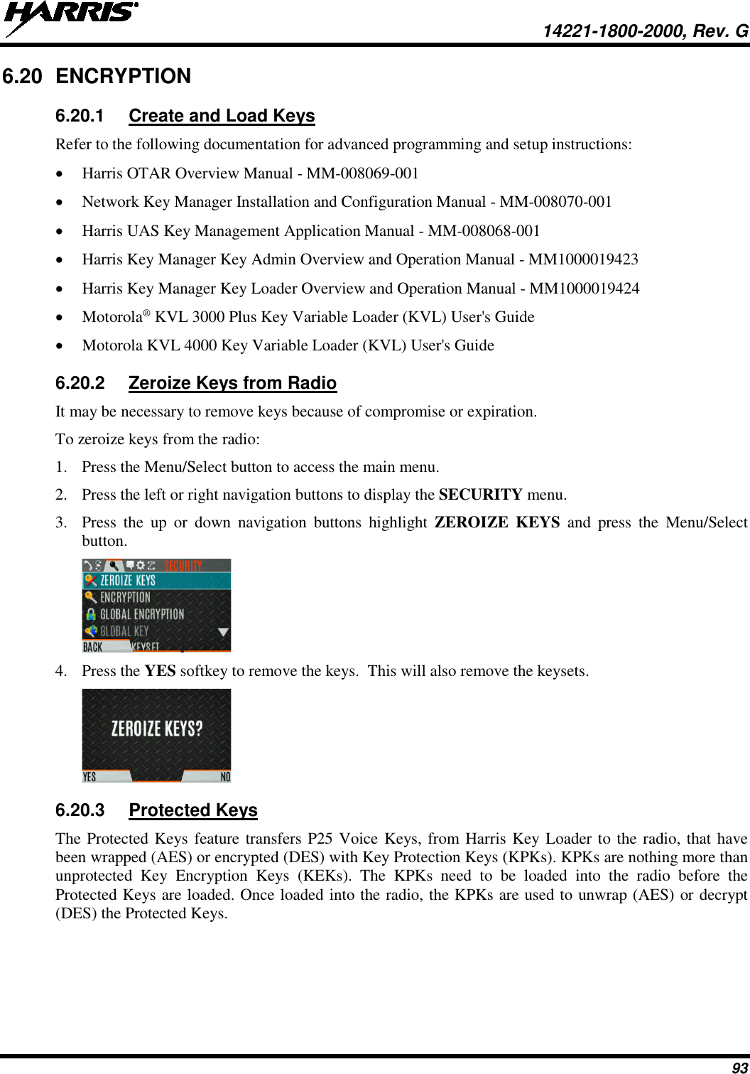
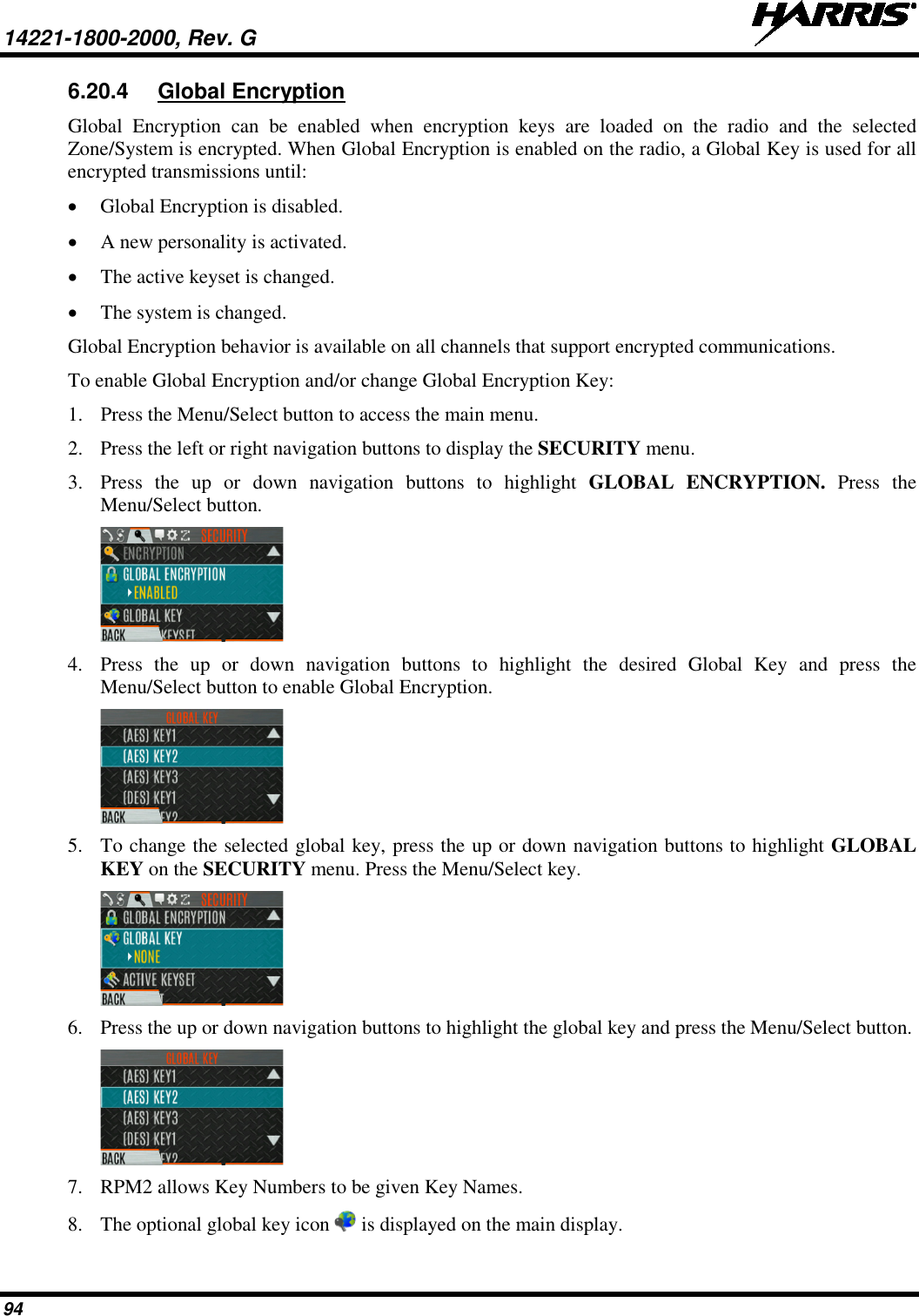
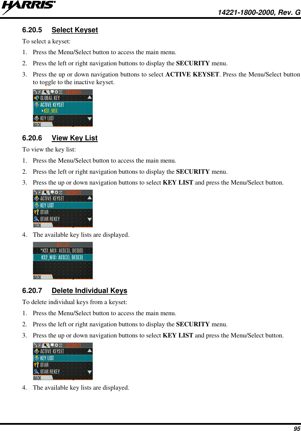
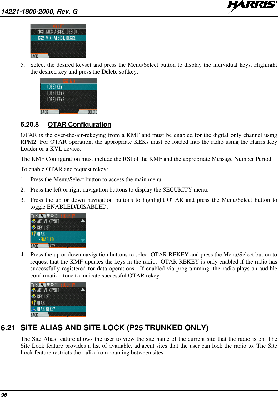
Contents
- 1. User Manual 1
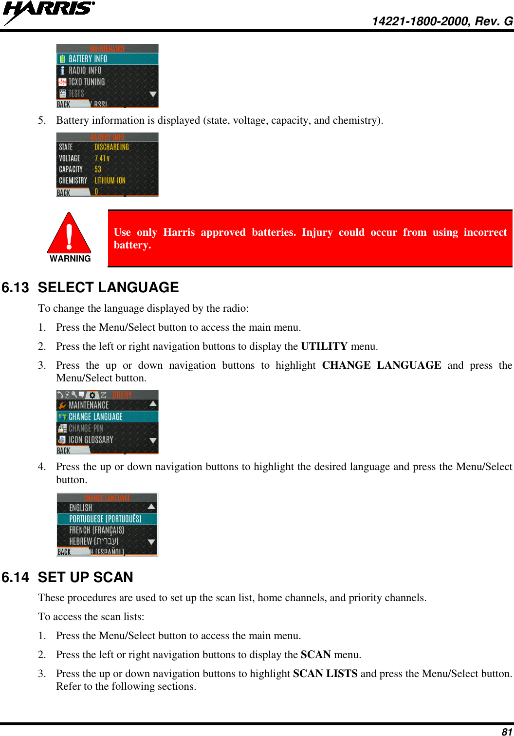
- 2. User Manual 2
User Manual 2