Exhibit8
2SHUDWRU·V0DQXDO
KME-200
EDACS Mobile Radio
%$

2
This manual is published by Ericsson Inc., without any warranty. Improvements and changes to
this manual necessitated by typographical errors, inaccuracies of current information, or
improvements to programs and/or equipment, may be made by Ericsson Inc., at any time and
without notice. Such changes will be incorporated into new editions of this manual. No part of this
manual may be reproduced or transmitted in any form or by any means, electronic or mechanical,
including photocopying and recording, for any purpose, without the express written permission o
f
Ericsson Inc.
Copyright © December 1998, Ericsson Inc.

3
SAFETY INFORMATION ..........................................................4
SAFE DRIVING RECOMMENDATIONS FOR USERS OF MOBILE
RADIOS RECOMMENDED BY AAA .............................................. 5
OPERATING RULES AND REGULATIONS.............................5
OPERATING TIPS.......................................................................... 6
INTRODUCTION.......................................................................7
CONTROLS.................................................................................... 9
DISPLAY....................................................................................... 11
KME- Display.......................................................................... 11
STATUS INDICATORS ................................................................ 12
TX/RX INDICATOR ...................................................................... 13
ALERT TONES............................................................................. 14
BASIC OPERATION ...............................................................14
TURNING THE RADIO ON .......................................................... 14
SELECTING OR CHANGING CHANNELS .................................. 15
CHANGING SYSTEMS ................................................................ 15
RECEIVING A CALL..................................................................... 15
TRANSMITTING A BASIC CALL.................................................. 16
CHANNEL GUARD....................................................................... 16
To Disable Channel Guard (Decode): .................................... 16
To Enable Channel Guard:..................................................... 18
RADIO MENU OPERATION......................................................... 18
SCAN OPERATION...................................................................... 20
SCAN ON/OFF....................................................................... 20
To Add Channels To The Scan List ....................................... 21
To Remove Channels From The Scan List ............................ 22
PHONE CALLS (DTMF) ............................................................... 23
Initiating A Phone Call From Memory..................................... 23
Initiating A Phone Call From The DTMF Microphone............. 25
EMERGENCY OPERATION......................................................... 26
Receiving A Call ..................................................................... 27
Transmitting A Call ................................................................. 28
Receiving An Emergency Call................................................ 29
Transmitting An Emergency Call............................................ 29
TYPE 99 OPERATION ................................................................. 30
Receiving An Individual, Group or Supergroup Call............... 30
Transmitting A Status Message ............................................. 32
Emergency Transmissions..................................................... 34
Base Station Calls .................................................................. 34
TABLE OF CONTENTS

4
SAFETY INFORMATION
The operator of any mobile radio should be aware of certain hazards
comEMER to the operation of vehicular radio transmissions. A list of
several possible hazards is given:
1. Explosive Atmospheres - Just as it is dangerous to fuel a vehicle
with the motor running, similar hazards exist when operating a
mobile radio. Be sure to turn the radio off while fueling a vehicle.
Do not carry containers of fuel in the trunk of a vehicle if the radio
is mounted in the trunk
2. Interference to Vehicular Electronics Systems - Electronic fuel
injection systems, electronic anti-skid braking systems, electronic
cruise control systems, etc., are typical electronic systems that may
malfunction due to the lack of protection from radio frequency
energy present when transmitting. If the vehicle contains such
equipment, consult the dealer and enlist their aid in determining the
expected performance of electronic circuits when the radio is
transmitting.
3. Dynamite Blasting Caps - Dynamite blasting caps may be caused
to explode by operating a radio within 500 feet of the blasting caps.
Always obey the "Turn Off Two-Way Radios" signs posted where
dynamite is being used.
When transporting blasting caps in your vehicle:
a. Carry the blasting caps in a closed metal box with a soft
lining.
b. Leave the radio OFF whenever the blasting caps are
being put into or removed from the vehicle.
4. Radio Frequency Energy - To prevent burns or related physical
injury from radio frequency energy, do not operate the transmitter
when anyone outside of the vehicle is within two feet of the antenna.
5. Liquefied Petroleum (LP) Gas Powered Vehicles - Mobile radio
installations in vehicles powered by liquefied petroleum gas with the
LP gas container in the trunk or other sealed-off space within the
interior of the vehicle must conform to the National Fire Protection
Association standard (NFPA) 58 requiring:

5
• The space containing the radio equipment shall be isolated by a seal
from the space containing the LP gas container and its fittings.
• Outside filling connections shall be used for the LP gas container.
• The LP gas container shall be vented to the outside of the vehicle.
SAFE DRIVING RECOMMENDATIONS FOR
USERS OF MOBILE RADIOS RECOMMENDED
BY AAA
• Read the literature on the safe operation of the radio.
• Keep both hands on the steering wheel and the microphone in its
hanger whenever the vehicle is in motion.
• Place calls only when vehicle is stopped.
• When talking from a moving vehicle is unavoidable, drive in the
slower lane. Keep conversations brief.
• If a conversation requires taking notes or complex thought, stop the
vehicle in a safe place and continue the call.
• Whenever using a mobile radio exercise caution.
OPERATING RULES AND REGULATIONS
Two-way FM radio systems must be operated in accordance with the
rules and regulations of the local, regional or national government
In the United States, the KME radio must be operated in accordance
with the rules and regulations of the Federal Communications
Commission (FCC). As an operator of two-way radio equipment, you
must be thoroughly familiar with the rules that apply to your particular
type of radio operation. Following these rules helps eliminate confusion,
assures the most efficient use of the existing radio channels, and results
in a smoothly functioning radio network. When using your two-way
radio, remember these rules:
1. It is a violation of FCC rules to interrupt any distress or emergency
message. As your radio operates in much the same way as a
telephone "party line", always listen to make sure that the channel

6
is clear before transmitting. Emergency calls have priority over all
other messages. If someone is sending an emergency message - such
as reporting a fire or asking for help in an accident - KEEP OFF
THE AIR!
2. The use of profane or obscene language is prohibited by Federal
law.
3. It is against the law to send false call letters or false distress or
emergency messages. The FCC requires that you keep conversations
brief and confine them to business. To save time, use coded
messages whenever possible.
4. Using your radio to send personal messages (except in an
emergency) is a violation of FCC rules. You may send only those
messages that are essential for the operation of your business.
5. It is against Federal law to repeat or otherwise make known anything
you overhear on your radio. Conversations between others sharing
your channel must be regarded as confidential.
6. The FCC requires that you identify yourself at certain specific times
by means of your call letters. Refer to the rules that apply to your
particular type of operation for the proper procedure.
7. No changes or adjustments shall be made to the equipment except by
an authorized or certified electronic technician.
Under U.S. law, operation of an unlicensed radio transmitter within
the jurisdiction of the United States may be punishable by a fine of up
to $10,000, imprisonment for up to two years, or both.
OPERATING TIPS
The following conditions tend to reduce the effective range of two-way
radios and should be avoided whenever possible:
• Operating the radio in areas of low terrain, or while under power
lines or bridges.
• Obstructions such as mountains and buildings.
IMPORTANT

7
In areas where transmission or reception is poor, some improvement
may be obtained by insuring that the antenna is vertical. Moving a few
yards in another direction or moving to a higher elevation may also
improve communication.
INTRODUCTION
This manual describes the operation for the Ericsson KME- Mobile
radio. The KME radio is a high performance FM mobile radio providing
reliable two-way communication in a Trunked radio system
The KME- radio can be programmed with multiple systems or a single
system and up to 128 channels. The KME- radio includes a 14-segment,
eight character, alphanumeric display.
The KME- can be programmed with a single system and up to 16
channels. The KME- radio includes a 7-segment, five character numeric
display.
The KME- radio can be programmed to operate with any of the
following Trunked radio system platforms:
DTMF
Channel Guard
Type 99
The KME- is a versatile radio designed to meet almost all Conventional
applications. The KME radio is available in numerous splits in the VHF
and UHF bands. Both the 20 watt and the 40 watt units, can be
programmed for low or high power on a per channel basis. The
following table provides a complete list of the KME- radios model
numbers.

8
Table 1 – KME- Radio Model Numbers
KME-
Radio Model # Description
KRD 103 143/1 136-156 MHz, 20 W
KRD 103 143/2 150.8-174 MHz, 20 W
KRD 103 143/3 403-440 MHz, 20 W
KRD 103 143/4 440-470 MHz, 20 W
KRD 103 143/5 470-512 MHz, 20 W
KRD 103 143/6 136-156 MHz, 40 W
KRD 103 143/7 150.8-174 MHz, 40 W
KRD 103 143/8 403-440 MHz, 40 W
KRD 103 143/9 440-470 MHz, 40 W
KRD 103 143/10 470-512 MHz, 40 W
KRD 103 143/21 806-825, 851-869 MHz, 25 W
KRD 103 143/31 896-902, 935-941 MHz, 25 W
9
SCAN
M
SP1SCAN P2 CGPG
ON/OFF/VOLUME
CHANNEL
SELECTOR INCREMENT/
SCAN ADD SCAN
ON/OFF ACCESS RADIO
MENU
DECREMENT/
SCAN DELETE
MICROPHONE
JACK
MONITOR/CLEAR TX/RX INDICATOR
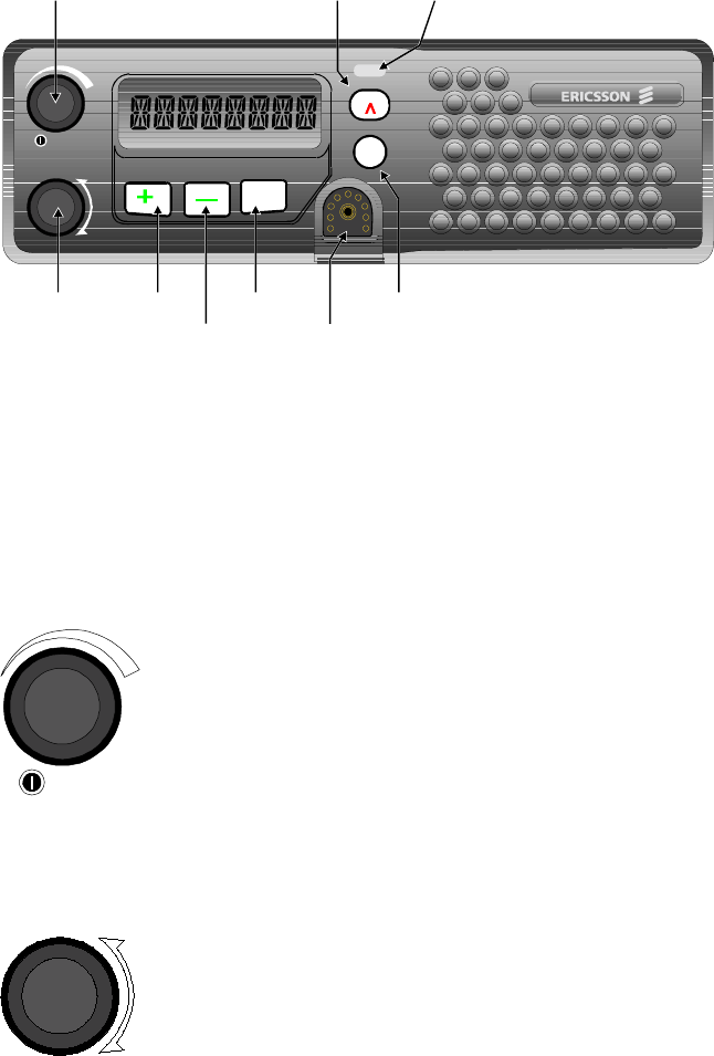
Figure 1 – KME- Radio Front View
CONTROLS
All the controls for the KME- mobile radio are located on the front of
the control unit and described below:
ON/OFF Volume Knob
This knob powers the radio ON/OFF and controls the
volume level of the received audio at the speaker. Rotate
the knob counterclockwise to turn the volume down.
Rotate the knob clockwise to turn the volume up. Rotate
the knob counterclockwise until it clicks and then stops,
to turn the radio OFF. When the knob is in the OFF
position, rotate the knob clockwise until the knob clicks
to turn the radio ON.
System/Group Channel Knob
This rotary knob is used to select the systems or
groups/channels, depending upon programming. This 16
position knob has no stop. See System/Group
Channel Selection for more details.

10
Increment/Scan Add Button
This button used in conjunction with the SCAN button
to add channels to the scan list. This button is also used
to increment to the next item in the menu.
Decrement/Scan Delete Button
This button is used in conjunction with the SCAN
button to remove channels from the scan list. This
button is also used to decrement to the previous item in
the radio menu.
Scan On/Off Button
This button is used toggle the scan operation on and off.
In conjunction with the + and – buttons, this button is
also used to add the selected channel to the scan list and
remove the selected channel from the scan list.
EMER Button
This button has two functions:
1. Press and hold the button for at least 1 second to unsquelch the
receiver and allow the user to hear all transmissions on the channel.
All decoders are defeated when the button is pressed. This allows
the user to check the setting of the volume control and to Monitor
the channel before transmitting.
2. Press and release the button (less than 1 second), to enable and
disable decode Channel Guard. At the same time, the selective
signaling state (Type 99, Enhanced and Multi-tone) toggles between
Monitor mode and selective mode.
M Button
This button provides access to the KME- menu. The
KME- menu allows the user to change radio operating
parameters, select preprogrammed calls from a list, etc.
11
DISPLAY
KME- Display
SP1SCANP2CGPG
EIGHT
CHARACTER
ALPHANUMERIC
DISPLAY
Selective Signaling
ON/OFF
Scan
Channel Priority 2
Channel
Scan
ON/OFF Channel Guard
ON/OF
F
Priority 1
Channel
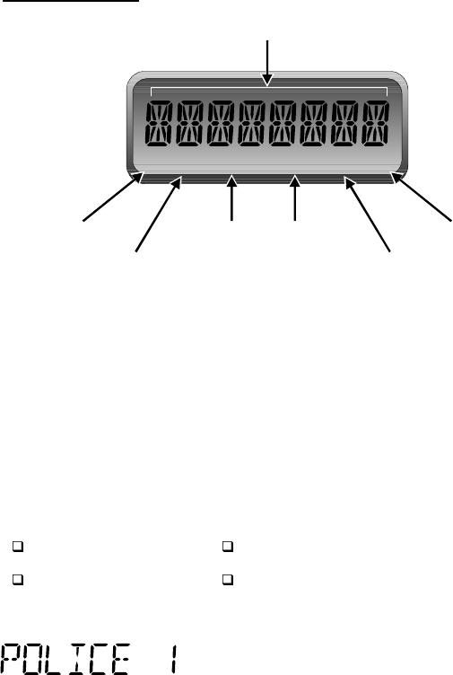
Figure 2 - KME- Display
The KME- includes an eight character 14-segment display and six status
icons. The eight character first line is used to display the selected
channel, menu items and miscellaneous operating conditions. When the
radio is programmed a personality or computer file is downloaded into
the radio. The personality defines how the radio will operate and is used
to tailor the operation of the radio for each application. Since the KME
radio clearly displays alphanumeric characters, an eight character name
can be created for each of the following items:
Systems Individual Calls
Channels Group Calls
The KME- radio displays the selected channel
by displaying the selected channel name as
defined in the personality. For example, this is
what will appear in the display if the name for
channel 4 is defined in the personality as
“Police 1”.

12
STATUS INDICATORS
The status indicators or icons are located at the bottom of the display
and provide an indication of various radio operating characteristics.
The S icon is used for channels in the scan list. The S
icon turns on if the selected channel is part of the scan
list. The scan list is a group of channels the radio
continuously Monitors for activity. This list can be
modified by the radio programmer or by the radio user.
The P1 icon is used for priority 1 channels. The P1 icon
turns on when the selected channel is defined as the
priority 1 channel or when the radio receives a call on
the priority 1 channel. In scan mode, channels defined
as priority channels have precedence over non-priority
channels. If a priority 1 channel is decoded, the radio
will drop a call while on a non-priority channel or a
priority 2 channel and then switch to the priority 1
channel to receive the call. This channel will also be
scanned more often than non-priority channels and the
priority 2 channel.
The SCAN icon indicates the condition of the SCAN
mode. The SCAN button is used to toggle scan ON and
OFF. When scan is ON, the radio Monitors all the
channels in the scan list for any activity. The SCAN
icon turns on when the scan mode is enabled.
The P2 icon represents priority 2 channels. The P2 icon
turns on when the selected channel is defined as the
priority 2 channel or when the radio receives a call on
the priority 2 channel. In scan mode, channels defined
as priority channels have precedence over non-priority
channels. If a priority 2 channel is decoded, the radio
will drop a call while on a non-priority channel and then
switch to the priority 2 channel to receive the call. This
channel will also be scanned more often than other non-
priority channels, but less than the priority 1 channel.

13
The CG icon represents decode Channel Guard. When
the user selects a channel preprogrammed with decode
Channel Guard, the CG icon turns on. Channels
programmed with Channel Guard only allow the user to
hear calls carrying the equivalent Channel Guard tones
or digital codes. This reduces the amount of "channel
chatter" the user hears.
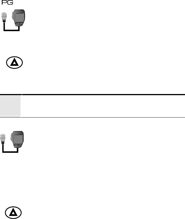
The PG icon represents selective signaling. When the
user selects a channel preprogrammed with Multi-tone
or Type 99 tone signaling, the PG icon turns on.
Selective signaling is used to initiate individual calls,
group calls, all calls, etc. When the radio is in the
Monitor mode the PG icon flashes.
TX/RX INDICATOR
This indicator is located above the EMER button. This
indicator contains a red LED and green LED. When the
radio is transmitting the red LED turns on. When the
radio is receiving a call, the green LED turns on.
14
ALERT TONES
The KME radio generates a number of unique audible alert tones or
“beeps” to indicate various operating conditions. The alert tone feature
can be enabled or disabled through PC Programming. All of the KME
alert tones are described in the following sections:
BASIC OPERATION
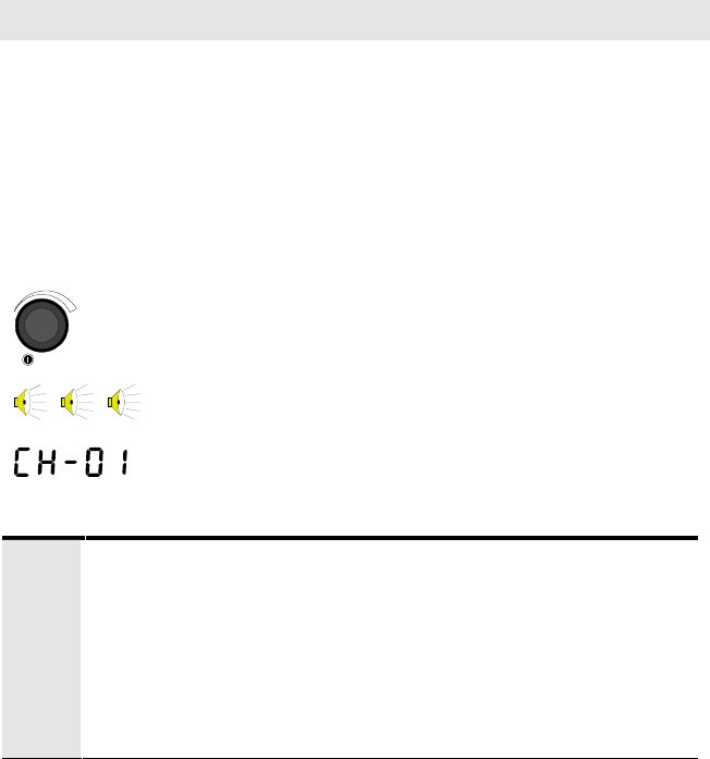
TURNING THE RADIO ON
Typically, mobile radio installations require the vehicle ignition switch
to be in the Accessory or Run position before the radio will power ON.
In some applications, the radio is wired directly to the battery and the
radio will power ON regardless of the setting of the vehicle ignition.
Verify with the installer, how the radio has been connected.
From the OFF position, rotate the ON/OFF Volume
knob clockwise until the knob clicks. The radio
performs a diagnostic test and then sounds three short
tones to indicate the radio has passed the diagnostic test
and is ready for operation. The display comes ON and
indicates the currently selected channel.
?
The KME mobile preserves the following data from the
previous operating state:
• Channel Number (unless preprogrammed with a power-
up channel)
• Scan ON/OFF State
• Scan List
• Radio Enable/Disable

15
SELECTING OR CHANGING CHANNELS
Rotate the Channel Selector Knob clockwise or
counterclockwise until the desired channel appears in
the display.
The Channel Knob is a continuous rotary knob that is
used to select the desired channel from a
preprogrammed list of channels. Rotate the knob
clockwise to increment to the next channel in the list.
When the end of the list is reached the radio will wrap
to beginning of the list. Rotate the knob
counterclockwise to decrement to the previous channel
in the list.
CHANGING SYSTEMS
1. Press the M button. This will bring up the KME
radio main menu.
2. Press the + or - buttons to scroll through the list of
preprogrammed systems.
3. Once the desired system appears in the display,
press the M button to accept the change, exit the
radio menu and return to the normal display.
RECEIVING A CALL
1. Make sure the radio is ON. Select the proper system
and channel as described in the previous sections.
2. Adjust the volume to the desired level by pressing
and holding the EMER button for at least l second.
Noise will be heard if there is no activity on the
channel.
3. When the radio receives a call, the green receive
indicator will light and audio will be present at the
speaker.
16
TRANSMITTING A BASIC CALL
1. Make sure the radio is ON. Select the desired
system and channel as described in the previous
sections.
2. Observe the TX/RX indicator for any activity on the
channel. Never transmit with the green RX indicator
ON.
3. Press and hold the EMER button for at least l second
to Monitor the channel for activity. Noise will be
heard if there is no activity on the channel. This will
also help in setting the volume level to the desired
level.
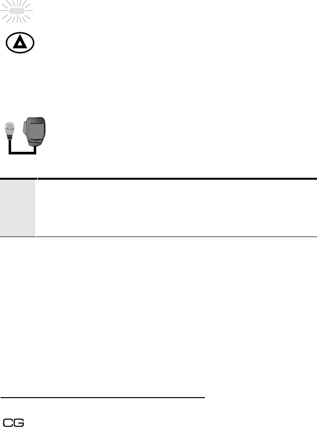
4. Remove the microphone from the hookswitch.
Holding the microphone approximately 2 inches
from your mouth, press the PTT button on the side of
the microphone and speak in the microphone.
?Always speak in a normal tone of voice. Hold the microphone
cupped in your hand and approximately three (3) inches from
your mouth. Shouting will degrade your transmission, so do
not speak any louder than normal.
5. When you have finished speaking, release the PTT
button and wait for a reply.
CHANNEL GUARD
Channel Guard is a method of reducing "channel chatter" by equipping
receivers with a device that only allows calls with the correct signaling
to be heard by the user. Channel Guard is defined in the radio
personality.
To Disable Channel Guard (Decode):
If Channel Guard is ON, the CG status indicator will be ON.

17
Press and release the EMER button (less than l second) to
turn decode Channel Guard OFF. The CG status indicator
will turn OFF. The radio will always transmit with Channel
Guard unless the channel is programmed without Channel
Guard.
?The radio can be programmed to disable Channel Guard by
removing the hookswitch .
18
To Enable Channel Guard:
If Channel Guard is OFF, the CG status indicator will be
OFF.
Press and release the EMER button (less than l second) to
turn decode Channel Guard ON. The CG status indicator
will turn ON. The radio will always transmit with Channel
Guard unless the channel is programmed without Channel
Guard.
RADIO MENU OPERATION
There are up to 12 main menu items available. For each main menu item
there are multiple submenu items to select from. The features enabled in
the radio personality define which main menu items are available and
will appear when the radio user accesses the radio menu. The following
procedure describes how to access and use the radio menu:
1. Press the M button to access the KME Radio Main
Menu.
2. Press the + button to move to the next item in the
main menu. Press the - button to move to the
previous item in the main menu.
3. Press the M button again to select any item from the
menu.
The radio will enter the main menu at the last changed item in the menu. If the
menu has not been accessed since the last power cycle, the radio will bring up
the first item in the menu list. Table 2 shows how the main menu items will
appear in the KME- radio and the KME- radio. The flowchart in Figure 3 shows
movement through the entire menu including all submenu items. Error!
Reference source not found. provides a complete description of all radio menu
items.
19
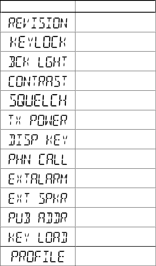
Table 2 – KME Radio Main Menu Display
KME Main Menu Description
Software Version
Backlight Adjust
Display Contrast
Squelch Adjust
Phone Calls
Car Horn Alert
Internal/External Speaker
Public Address Speaker
System Change
Figure 3 - Radio Menu Flowchart
20
SCAN OPERATION
The KME- mobile radio can be set up to scan (Monitor) up to 16
channels on the selected system. The scanned channels may be any
frequency within the frequency band limits of the radio. If the radio
picks up activity on one of the scanned channels, the radio will switch to
the channel and allow the user to receive the call. When the call is done,
the radio automatically switches back to the knob-selected channel.
When scan is turned ON, the radio scans all the channels in the scan list.
Initially, the scan list is created when the radio is PC Programmed, but
the KME radio allows the user to modify the scan list.
The scan list can also include a priority 1 channel and a priority 2
channel. In scan mode, channels defined as priority channels have
precedence over non-priority channels. If a call on a priority 2 channel is
received, the radio will drop a call while on a non-priority channel and
switch to the priority channel to receive the call. If a call on a priority 1
channel is received, the radio will drop a call while on a non-priority
channel or a priority 2 channel and then switch to the priority 1 channel
to receive the call. Priority channels are also scanned more often than
non-priority channels.
The following sections describe how to use the scan feature on the
KME- mobile radio.
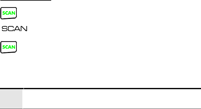
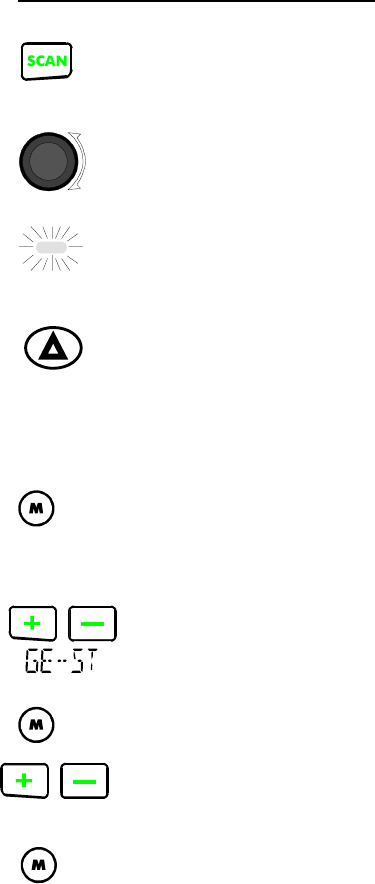
SCAN ON/OFF
1. To turn the scan feature ON, press the SCAN button.
2. The SCAN icon should appear in the radio display.
3. To turn the scan feature OFF, press the SCAN button
again.
4. The SCAN icon should disappear from the radio
display.
21
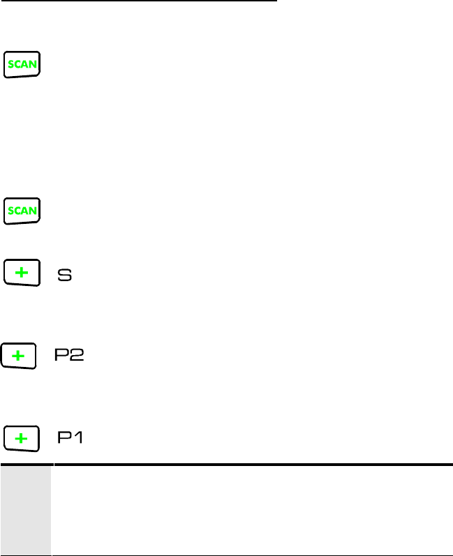
To Add Channels To The Scan List
1. Press the SCAN button if necessary to turn scan
OFF. The SCAN icon should not be visible in the
display. The scan list cannot be modified while the
radio is scanning.
2. The SCAN button is used in conjunction with the +
button to add channels to the scan list as non-priority,
priority 2 or priority 1.
3. Press and hold the SCAN button.
4. Press the + button once, the S icon appears and the
channel is added to the scan list as a non-priority
channel.
5. Press the + button again (twice), the P2 icon appears
and the channel is added to the scan list as the
priority 2 channel.
6. Press the + button again (three times), the P1 icon
appears and the channel is added to the scan list as
the priority 1 channel.
?If you define a channel as priority 1 or priority 2, the radio
will automatically switch the previously defined priority 1 or
priority 2 channel to non-priority. The channel is not removed
from the scan list.
22
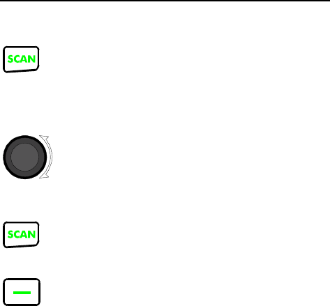
To Remove Channels From The Scan List
1. Press the SCAN button if necessary to turn scan
OFF. The SCAN icon should not be visible in the
display. The scan list cannot be modified while the
radio is scanning.
2. Using the channel knob, select the desired channel
to remove from the scan list. If the channel is part of
the scan list, the S, P1 or P2 icon will appear in the
display when the channel is selected.
3. Press and hold the SCAN button.
4. Press and release the - button. The S, P1 or P2 icon
will disappear from the display and the channel is
removed from the scan list.
23
PHONE CALLS (DTMF)
DTMF operation is enabled on a per channel basis in the radio
personality. Up to X phone numbers can be pre-programmed into the
radio and recalled by the user. Radio operators equipped with a DTMF
microphone can initiate a phone call to any number with the keypad on
the microphone.
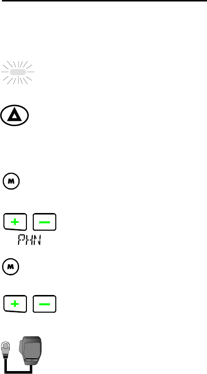
Initiating A Phone Call From Memory
1. Select the desired system and channel as described
in the Basic Operation section on page 14. DTMF
must be enabled on the channel.
2. Observe the TX/RX indicator for any activity on the
channel. Never transmit when the green RX
indicator is ON.
3. Press the EMER button to be sure there is no
activity on the channel. Typically, if there is noise,
there is no channel activity.
4. Remove the microphone from the hookswitch.
5. Press the M button. This will bring up the KME
radio main menu.
6. Press the + or - buttons until the PHN menu item
appears.
7. Press the M button to view the list of pre-
programmed phone numbers (1-3).
8. Press the + or - buttons to scroll through the pre-
programmed phone numbers (PHN 1 thru PHN 3).
9. When the desired phone call entry appears appears
in the display, press and release the PTT button on
the side of the microphone. The red TX indicator
should light and the radio will initiate the phone
call.
24
10. When the person answers, press PTT button to talk
and release the PTT button to listen.
25
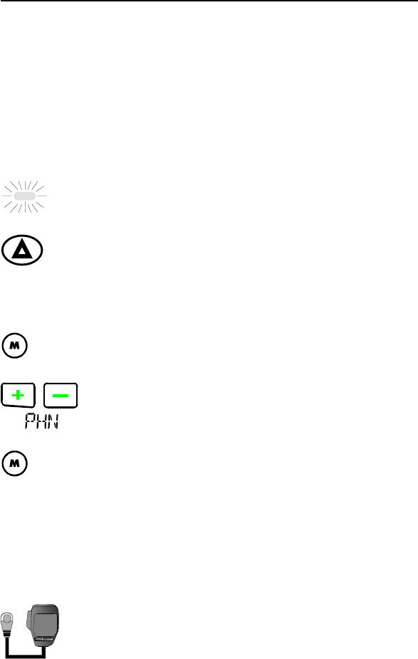
Initiating A Phone Call From The DTMF Microphone
By entering a new number from the DTMF microphone any of the 3
stored phone numbers can be temporarily changed. The new number
does not change the pre-programmed number. The following procedure
describes how to enter a phone number and initiate a phone call from the
DTMF microphone:
1. Select the desired system and channel as described
in the Basic Operation section on page 14. DTMF
must be enabled on the channel.
2. Observe the TX/RX indicator for any activity on the
channel.
3. Press the EMER button to be sure there is no
activity on the channel. Typically, if there is noise,
there is no channel activity.
4. Remove the microphone from the hookswitch.
5. Press the M button. This will bring up the KME
radio main menu.
6. Press the + or - buttons until the PHN menu item
appears.
7. Press the M button to view the list of pre-
programmed phone entries (PHN 1 - PHN 3).
8. With any of the pre-programmed phone entries
displayed, enter the new phone number from the
DTMF mic. The digits will appear on the right and
rotate left as new digits are entered. The maximum
is 13 characters.
9. When you have finished entering the phone number,
press and release the PTT button on the side of the
microphone. The red TX indicator should light and
the radio will initiate the phone call.
10. When the person answers, press PTT button to talk
and release the PTT button to listen.

26
EMERGENCY OPERATION
Emergency signaling can be transmitted when operating in the
conventional mode. Emergency signaling will transmit 5 times with a
delay between each transmission. To send an emergency call on the
selected conventional system and channel (or on an optionally pre-
programmed conventional emergency system and channel), proceed as
follows:
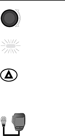
Press and hold the red button for approximately one second (this
time is programmable and, therefore, could be longer or shorter; check
with the system administrator). The radio turns on the TX indicator and
proceeds to transmit the pre-programmed emergency signaling sequence.
Emergency signaling is programmed to transmit in one of the following
methods:
METHOD 1: Signaling is transmitted on the selected channel. If the
channel is changed the emergency signaling will continue
to be transmitted on the newly selected channel.
METHOD 2: Same as METHOD 1 but the radio will lock on to the
currently selected channel. Any attempts to change the
system or channel will be disabled.
METHOD 3: Signaling is transmitted on a pre-programmed conventional
emergency system and channel regardless of the selected
channel. In this case the selected channel is available for
voice transmission and the radio will periodically change
to the pre-programmed emergency system and channel to
send the emergency signaling and then change back to the
selected channel.
METHOD 4: Same as METHOD 3 but the radio will lock on to the pre-
programmed emergency system and channel. Any attempts
to change the system or channel will be disabled.
The emergency state can be cleared by turning the radio OFF and then
back ON.
27
Receiving A Call
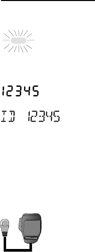
1. When the radio receives an Emergency call:
À The green TX/RX indicator will turn ON to
indicate the radio is receiving a carrier.
À The radio display will change. The radio will
alternate between displaying the selected
channel and the ID of the calling radio. The
radio will display “ID 12345”, where “12345”
is the radio ID.
À The radio displays the ID of all Emergency calls
decoded. When Channel Guard is enabled on
the channel, the user will only hear calls
intended for the user. When Channel Guard is
disabled, the user will hear all calls.
2. To respond to the call, remove the microphone from
the hookswitch. Hold the microphone approximately
2 inches from your mouth, press the PTT button on
the side of the microphone and speak in the
microphone.
3. There are three ways to clear the call from the
display:
À Wait, the display will timeout and return to the
normal channel display.
À Select another channel.
À Press the Push-To-Talk, EMER, M or SCAN
button.
28
Transmitting A Call
1. Select the proper system and channel as described in
the Basic Operation on page 14.
2. Observe the TX/RX indicator for any activity on the
channel. Never transmit with the green RX indicator
ON.
3. Press and hold the EMER button for at least l
second to Monitor the channel for activity. Noise
will be heard if there is no activity on the channel.
This will also help in setting the volume level to the
desired level.
4. Remove the microphone from the hookswitch.
Holding the microphone approximately 2 inches
from your mouth, press the PTT button on the side
of the microphone and speak in the microphone.
5. When you have finished speaking, release the PTT
button and wait for a reply.
29
Receiving An Emergency Call
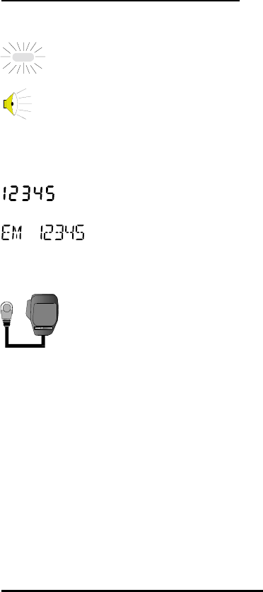
1. When the radio receives an emergency call:
À The green TX/RX indicator will turn ON to
indicate the radio is receiving a carrier.
À A single tone will sound to indicate the radio
has received an emergency call.
À The radio display “EM xxxxx,” where xxxxx is
the calling radio ID The display will alternate
between the selected channel and the ID of the
calling radio,.
À The user will hear the receive audio in the radio
speaker. Emergency transmissions are always
sent with Channel Guard.
2. To respond to the call, remove the microphone from
the hookswitch. Hold the microphone approximately
2 inches from your mouth, press the PTT button on
the side of the microphone and speak in the
microphone.
3. There are three ways to clear an emergency call
from the display:
À Wait, the display will timeout and return to the
normal channel display.
À Select another channel.
À Press the Push-To-Talk, EMER, M or SCAN
button.
Transmitting An Emergency Call
Emergency transmission can be programmed to go out on the selected
channel or a pre-programmed emergency channel. To send an
emergency, simply press the emergency button for approximately 1
second. The radio will send out the radio ID and the emergency
message.
30
TYPE 99 OPERATION
Type 99 is Ericsson’s proprietary method for in-band, two-tone
sequential signaling. It is a conventional signaling protocol used to
control the muting and unmuting of a radio. This signaling is commonly
used for selective calling of individual units or groups of units in a
conventional system. Type 99 is typically used in paging operations,
where a dispatcher is able to select which radio or radios are to be
selectively called.
If Type 99 has been setup, the radio can decode individual, group and
supergroup paging calls. When the radio decodes an appropriate Type
99 decode sequence, an alert sounds, the PG icon flashes and the radio
enters the Monitor mode.
Receiving An Individual, Group or Supergroup Call
1. Turn scan OFF. The radio cannot receive selective
calls with scan ON. When scan is enabled, the radio
automatically switches to the Monitor Mode and
Type 99 decode is disabled.
2. Select the proper system and channel as described in
the Basic Operation on page 14.
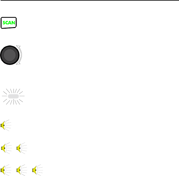
3. When the radio receives a selective call:
À The green TX/RX indicator will turn ON to
indicate the radio is receiving a carrier.
À For an individual call, a single ½ second tone
will sound to indicate the call is an individual
call.
For a group call, two short tones will sound to
indicate the call is a group call.
For a supergroup call, three short tones will
sound to indicate the call is a supergroup call.
31
À The radio switches to the Monitor mode and the
PG icon flashes.
4. To respond to the call, remove the microphone from
the hookswitch. Hold the microphone approximately
2 inches from your mouth, press the PTT button on
the side of the microphone and speak in the
microphone.
5. To end the call and return to the Selective Mode,
press the EMER button. The radio will remain in the
Monitor Mode and the PG icon will continue to
flash until the user presses the EMER button.
?At this point in the menu, radios equipped with a DTMF
microphone may enter any radio ID from the DTMF keypad.
1. When the desired individual ID or name appears in
the display, press the PTT button on the side of the
microphone and speak in the microphone. The red
TX indicator should light.
2. When you have finished speaking, release the PTT
and wait for a response (if expected). If your radio is
programmed to receive an individual
acknowledgement and does not receive an
acknowledgement, the radio will display FAIL.
3. When the call is complete, press the EMER button
and the radio will return to the Selective Mode.
32
Transmitting A Status Message
1. Turn scan OFF. The radio cannot transmit a status
message call with scan ON. When scan is turned ON,
the encoder is disabled and the radio is in the Monitor
mode.
2. Select the desired system and channel as described in
the Basic Operation section on page 14.
3. Observe the TX/RX indicator for any activity on the
channel. Never transmit with the green RX indicator
light ON.
4. Press and hold the EMER button for at least l second to
Monitor the channel for activity. Noise will be heard if
there is no activity on the channel. This will also help in
setting the volume level to the desired level.
5. Remove the microphone from the hookswitch.
6. Press the M button. This will bring up the KME radio
main menu.
7. Press the + or - buttons until the XXXX menu item
appears.
8. Press the M button to view the submenu items.
9. Press the + or - buttons to scroll through the submenu
items.
10. When STAT appears in the display, press the M button
to view list of preprogrammed individual calls.
33
11. Press the + or - buttons to scroll through the list of
preprogrammed individual calls. For KME- radios, this
list will consist of the radio ID for each individual call
as defined in the radio personality. For KME- radios,
this list will consist of the individual name for each
individual call as defined in the radio personality.
?At this point in the menu, radios equipped with a DTMF
microphone may enter any radio ID from the DTMF keypad.
12. When the desired individual ID or name appears in
the display, press the PTT button on the side of the
microphone and speak in the microphone. The red
TX indicator should light.
13. When you have finished speaking, release the PTT
and wait for a response (if expected).
14. When the call is complete, press the EMER button
and the radio will return to the Selective Mode.

34
Emergency Transmissions
The KME radio can be programmed and installed to send emergency
signals. To initiate an emergency call, the Option Cable (KRD 103
133/45) must be installed with a customer supplied emergency button or
switch. See the Installation Manual LZT 123 4452 for more information.
Emergency signaling is defined in the personality. The programmable
features related to emergency signaling are described below:
v The emergency can be programmed to transmit on the selected
channel, or on a pre-programmed Home/Emergency Channel.
v The emergency can be programmed with or without an
acknowledgement from the base station. If an acknowledgement is
required, the radio will display FAIL if the acknowledgement is not
received.
v The KME radio can also be programmed to send a silent emergency.
In a silent emergency, the radio transmits the emergency without any
indication of a transmission. The TX indicator does not light and all
received calls are muted until the user presses the PTT button. The
received calls are muted to keep from endangering the user that
declared the silent emergency.
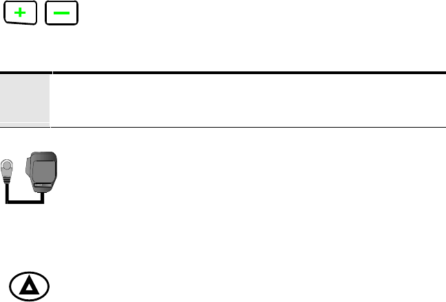
To Send An Emergency
Press and hold the emergency button for at least 1 second.
Base Station Calls
In an Enhanced environment, the radio is capable of receiving several
unique calls from the base station dispatcher. These calls do not require
a response from the user. The following sections describe each type of
call.
Interrogate Radio
The interrogate feature allows the dispatch base station to validate the
participation of a radio Monitoring the system. The base station sends
out a message to a particular radio that includes the radio ID and the
interrogate message. If the radio receives a call that includes its own ID
and the interrogate message, the radio responds by transmitting its own
radio ID back to the base station. The radio receives the call and
35
responds (transmits) back to the base station without providing any
indication to the radio user.
Disable Radio
The radio disable feature allows the dispatch base station to disable any
radio Monitoring the system. The base station sends out a message to a
particular radio that includes the radio ID and disable message. If the
radio receives a call that includes its own ID and the disable message,
the radio responds by transmitting its own radio ID back to the base
station. After responding to the base station, the radio enters a disabled
or kill mode. In the disable mode, the radio will receive calls, but no
audio is heard at the speaker. The Push-To-Talk button is also disabled.
The radio is disabled for all channels in the system. The radio will only
respond to an interrogate call or radio enable call.
Enable Radio
The radio enable feature allows the dispatch base station to reactivate or
enable any radio Monitoring the system that had previously been
disabled. The base station transmits a call to a particular radio that
includes the radio ID and the enable message. If the radio receives a call
that includes the its own radio ID and the enable message, the radio
responds by transmitting its own radio ID back to the base station. After
responding to the base station, the radio exits the disabled or kill mode.
Reset Radios
The reset radio feature allows the base station to reset a particular radio
on the system to the selective state. The base station sends out a message
to a particular radio that includes the radio ID and the reset message. If
the radio receives a call that includes its own ID and the radio reset
message, the radio responds by resetting the decoder back to the
selective state. The mobile radio does not send an acknowledgement
back to the base station.