HARRIS TR-420-A2 DM-15 User Manual 8 DM15 7 OEM Interface Manual
HARRIS CORPORATION DM-15 8 DM15 7 OEM Interface Manual
HARRIS >
Contents
- 1. Manual
- 2. 022202 revised Manual
Manual
DM-15
OEM Interface Manual
1
1Overview ................................................................................................................................................2
1.1 General ...........................................................................................................................................2
1.2 Operating Modes.............................................................................................................................3
1.3 Software..........................................................................................................................................3
1.4 Hardware ........................................................................................................................................3
1.4.1 Mechanical..................................................................................................................................4
1.4.2 Electrical.....................................................................................................................................5
1.5 References.......................................................................................................................................6
1.5.1 External Document Index.............................................................................................................6
1.6 Test/Certification Requirements.......................................................................................................6
2Hardware Requirements..........................................................................................................................6
2.1 Module Dimensions.........................................................................................................................6
2.2 External Interfaces...........................................................................................................................8
2.2.1 System Connector.......................................................................................................................8
2.2.2 Accessory Connector .................................................................................................................12
2.2.3 Antenna Connector....................................................................................................................13
2.3 Electrical Performance...................................................................................................................13
2.4 Mobile Station Power Class...........................................................................................................14
2.5 Power Consumption ......................................................................................................................14
2.5.1 Transmit/Talk Mode ..................................................................................................................14
2.5.2 Standby Mode............................................................................................................................14
2.5.3 Sleep Mode (Minimum DC Power consumption) .......................................................................14
2.6 Reliability......................................................................................................................................14
2.7 Environmental Requirements.........................................................................................................15
3External Control/Interface .....................................................................................................................16
3.1 Introduction...................................................................................................................................16
3.1.1 Common AT Command Ensembles............................................................................................16
3.1.2 IS-136 AMPS/DAMPS Ensembles.............................................................................................21
3.1.3 CDPD Ensembles ......................................................................................................................27
3.1.4 OEM Module Ensemble.............................................................................................................29
4Safety....................................................................................................................................................31
4.1 Exposure to Radio Frequency Signals ............................................................................................31
4.2 Module Operation .........................................................................................................................31
4.3 Posted Facilities ............................................................................................................................31
4.4 Electronic Devices.........................................................................................................................31
4.5 Blasting Areas...............................................................................................................................32
4.6 Potentially Explosive Atmospheres................................................................................................32
4.7 Vehicles ........................................................................................................................................32
4.8 For Vehicles Equipped with an Airbag...........................................................................................32
4.9 Responsible Use ............................................................................................................................32
2
1 Overview
The DM-15 module is intended for mounting into an application developer’s chassis to provide wireless
communication capability for the product. The target chassis could be in a wide variety of forms such as a
residential electric meter, a point of sale terminal, an alarm panel, or an automobile console. All initial
configuration, mode control, and operational commands are issued to the module over an RS-232 serial port
using a flexible AT command format. The module circuitry has been designed to meet the environmental
requirements of a large range of commercial and industrial users.
1.1 General
DM-15 is a fully RF shielded PCB assembly with dimensions of approximately 4 x 2 x .7 inches. It has three
external interfaces: a 30-pin system connector, a 16-pin accessory connector and a miniature coaxial RF
antenna connector.
Figure 1.1 -1: DM-15 Module
3
1.2 Operating Modes
The word “mode”, when applied to DM-15 can refer to either software modes or hardware modes. Desired
usage can be determined from the context. Software modes are the various ways in which DM-15 can be made
to send and receive wireless data. They are described briefly in Section 1.3 below. Hardware modes are the
various ways in which the functions of the 30-pin connector can be changed as needed for testing or to
configure DM-15 for different applications. Hardware modes are described in more detail in Section 2.
1.3 Software
DM-15 software options can be used to configure the module hardware to operate in a wide variety of cellular
voice and data communication modes. The first three software option packages to be delivered for the module
are described below.
1. IS-136 rev. B with IS-130/IS-135 asynchronous data and group 3 fax capability - This software provides
dual mode AMPS/ TDMA cellular communications over the 800 MHz cellular frequency band. The
module automatically switches between the legacy AMPS system and the newer digital IS-136 cellular
system based on system availability and/or manual selection by the host application.
2. CDPD release 1.1 capability - The Cellular Digital Packet Data (CDPD) system provides wireless data
communication at 19,200 bps using standard TCP/IP communication protocol. As such, it can extend full
Internet access to a user’s remote mobile platform. The CDPD system operates in the 800 MHz band
either sharing a traffic channel with the 800 MHz cellular voice system, or more commonly, being
permanently allocated a specific channel for packet data communications. A user is charged for the
number of kilobytes transferred rather than for the minutes of connect time as is normally the case for
cellular voice and data communications. This allows the user to remain continuously connected to the
CDPD network and experience minimal access delay to receive or transmit data.
3. AMPS 553 analog voice with burst data capability – This software option is being offered in response to a
need for a voice/data communications capability with high percentage geographical coverage over most of
the United States and Canada. The AMPS cellular system using circuit switched data is the only viable
option at this time. Although digital cellular systems with data capability are being deployed in several
locations around the county, it will be many years if ever before they have the coverage footprint of the
existing AMPS system. In addition to providing voice communication services, this software option
provides a built-in circuit switched burst data modem over the analog circuit switched cellular network.
V.27ter is used to transmit the data, which is heavily encoded to combat the fading in the mobile
environment. The burst data is operated in a half duplex mode. The module is capable of transmitting or
receiving 250 bytes of data over the analog circuit switched cellular network in less than 5 seconds. The
DTMF tones are used to switch between voice and data modes either locally, or by a remote
communication center.
All of the software platforms listed above include a serial bus multiplexing protocol capability that can be used
by the application developer to create multiple virtual communication channels with the DM-15 module over
the single serial port. A common example of the virtual channel application is providing simultaneous transport
of mode commands, data traffic, and status messages between the module and the main application control
microprocessor.
1.4 Hardware
The next two sections give a top-level overview of DM-15 as seen from the application developer’s
perspective. Hardware design details inside the DM-15 module are described in the “DM-15 Operational
Description”.
4
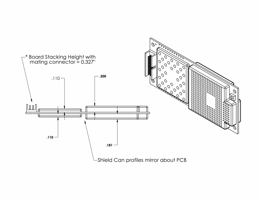
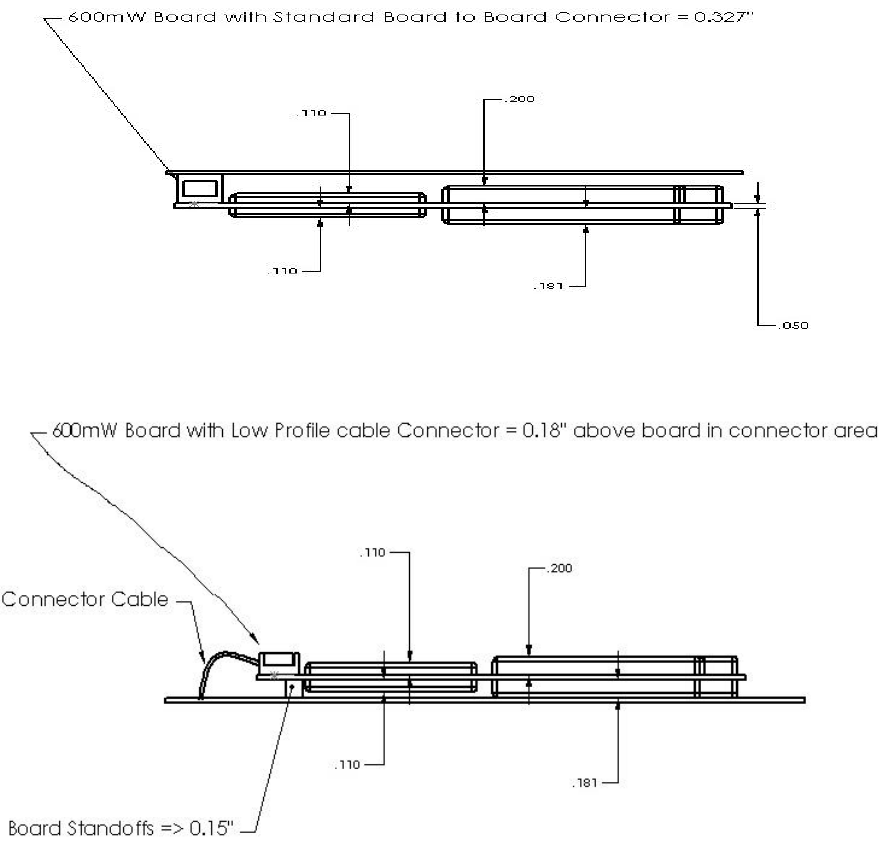
1.4.1 Mechanical
The DM-15 module has no mechanical elements other that the main PCB assembly. All critical electronic
components are shielded using sheet metal cans to prevent internal/external electromagnetic interference from
degrading the module’s performance and to prevent the module from interfering with other nearby devices.
Figure 1.4-1 shows a typical mounting configuration of the module with the main motherboard assembly. The
module is plugged into the fixed mating connector and secured with four screws to the standoff components.
Figure 1.4-1 Module Mounting Configuration
5
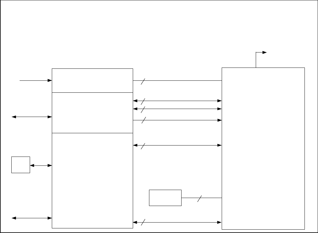
1.4.2 Electrical
Figure 1.4-2 shows an overview of the electrical interface between the DM-15 module and a typical
application.
Figure 1.4-2 DM-15 Electrical Interface
DM-15 Electrical Interface
Customer Application
HW
Voltage Regulator
Control Processor
Voice & Data Processing
Ÿ
Echo Cancelling
Ÿ
Noise Cancelling
Ÿ
Audio Power AMP
Ÿ
Data Conversion
DTE
Power
External Audio
Interface
Antenna
User Interface
6
1
Power & GND
Serial Interface
Wake
Analog Audio Interface
10
1
3
5
4
Clock REF
Option
SIM Device
DM-15
Module
PCM Audio Interface

6
1.5 References
1.5.1 External Document Index
• Cellular Digital Packet Data (CDPD) System Specification, Release 1.1, 19 January
1995, CDPD Forum
• IS-130, 800 MHz Cellular Systems TDMA Radio Interface Radio Link Protocol 1,
01 March 1995, EIA/TIA
• IS-135, 800 MHz Cellular Systems TDMA Services Async Data and Fax, April
1995, EIA/TIA
• IS-136.1, Revision A, TDMA Cellular/PCS Radio Interface Mobile Station - Base
Station Compatibility Digital Control Channel, October 1996, EIA/TIA
• IS-136.2, Revision A, TDMA Cellular/PCS Radio Interface Mobile Station - Base
Station Compatibility Traffic Channels and FSK Control Channel, October 1996,
EIA/TIA. Referred to here as ‘IS-136’.
• IS-137, Revision A, TDMA Cellular/PCS Radio Interface Minimum Performance
Standard for Mobile Stations, July 1996, EIA/TIA. Referred to here as ‘IS-137’.
1.6 Test/Certification Requirements
AMPS/DAMPS Configurations CDPD Configuration
FCC Part 22 FCC Part 22
FCC Part 15 Ameritech CDPD Certification
IS-137 Revision A GTE CDPD Certification
Bell Atlantic Mobile / Nynex CDPD Certification
AT&T CDPD Certification
2 Hardware Requirements
2.1 Module Dimensions
The physical dimensions of the DM-15 module are as indicated in the figure shown below. The electrical
interconnection to the optional accessory board is made through vertical header pins, which are part of the
accessory assembly. Dimensions given for shield-can height and overall module thickness are approximate at
this time. Note: All dimensions are in inches.
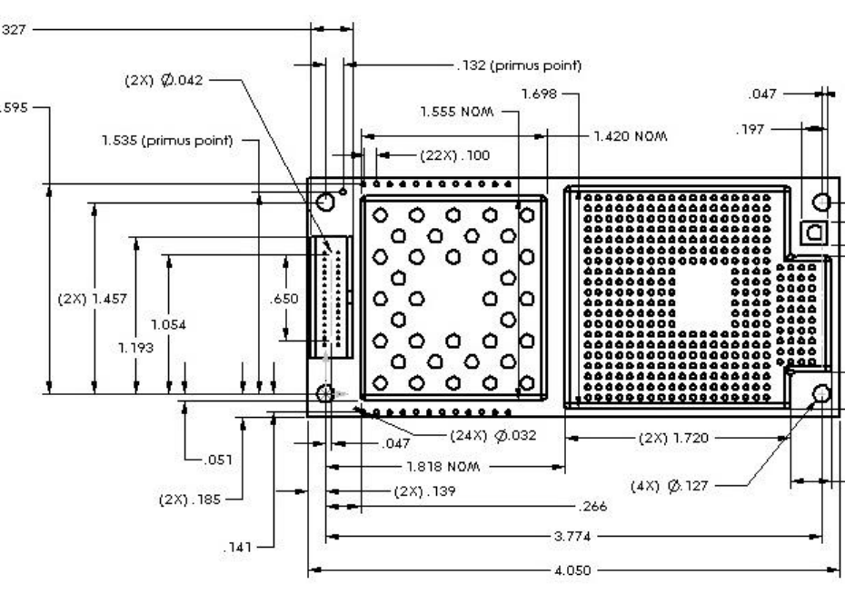
7
Figure 2.1-1 Module Dimensions
8
2.2 External Interfaces
**Warning : ESD Sensitive Devices*** Many of the pins on the external connectors interface
directly with integrated circuits within the module. Although all pins are protected against normal
ESD events, use appropriate precautions to prevent ESD damage.
2.2.1 System Connector
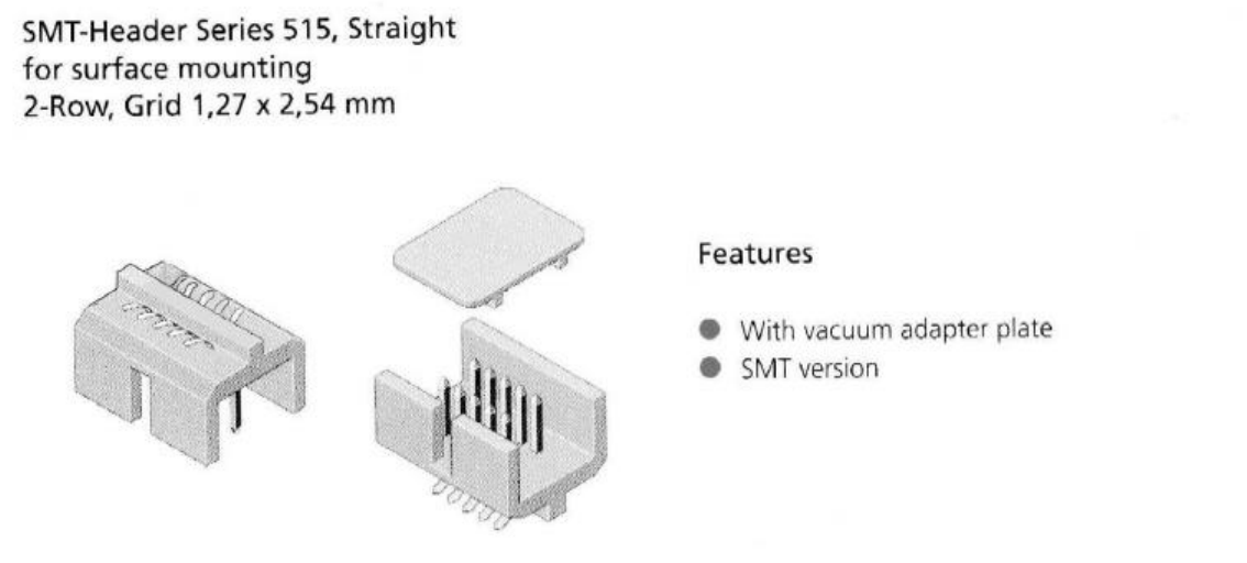
External interfaces to the module are made primarily through a 30-pin, standard 0.050 inch pitch,
ODU header shown below.
515-568
Figure 2.2-1 System Connector
9
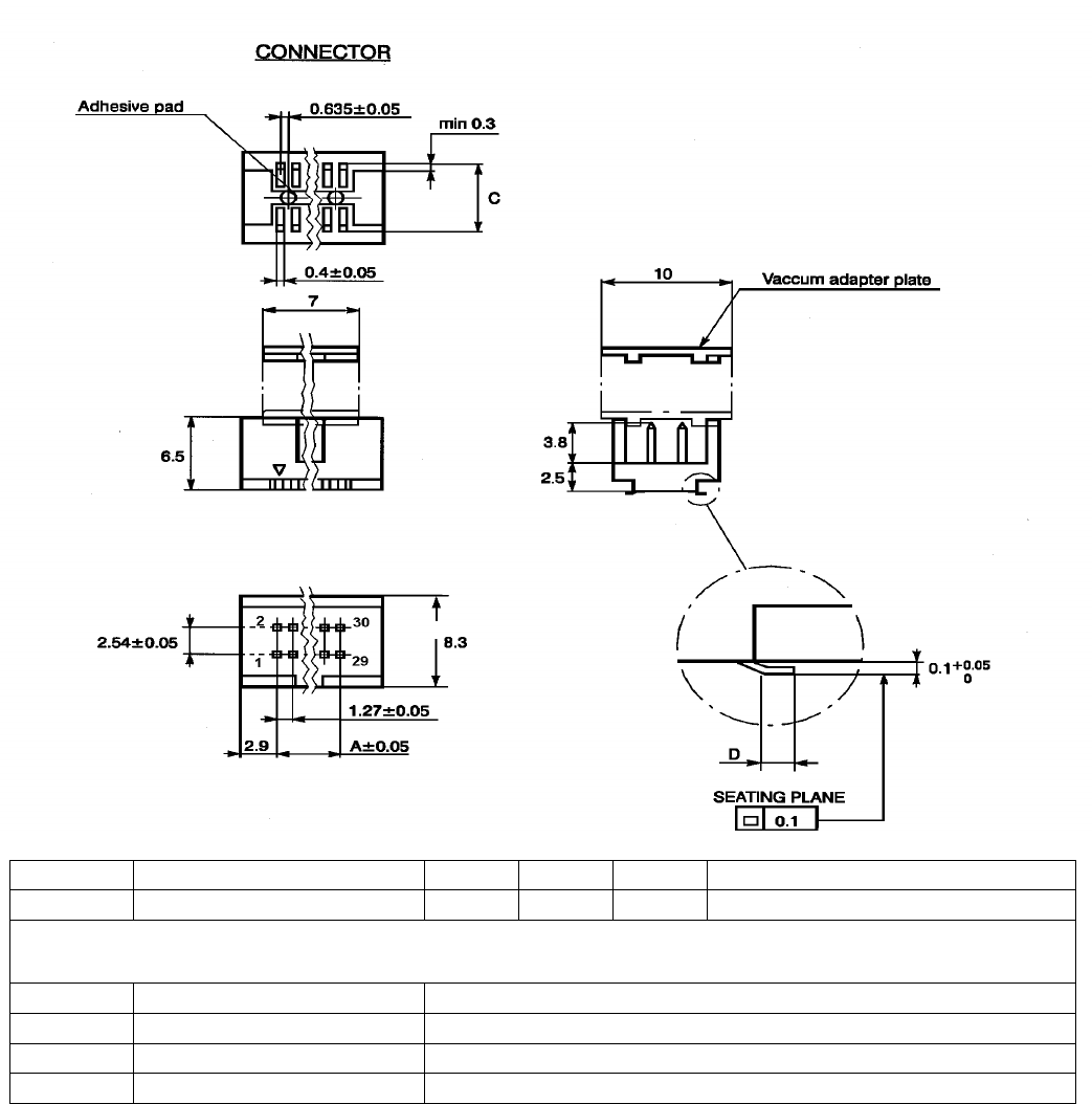
Position Part Number Dim A Dim B Dim C Height in mated condition
30 515.569.035.030.050 17.78 23.58 16.51 8.3 mm
ODU MINI-FIX Mating Connectors
Position Part Number Description
30 525.060.035.030.xxx Flex Cable Socket Connector
30 515.568.730.700.000 Locking Clip, Surface Mount Header to Flex Cable Socket
30 525.031.035.030.xxx SMT Board to Board Socket Connector
Figure 2.2-2 Connector Details

10
Table 1.2-1: 30-Pin System Connector Functions
Pin Signal Name Description TYPE
1GND Chassis Ground -
2GND/AD_in Chassis Ground (optionally A/D input) -/I
3AFMS Audio from module O
4GND Chassis Ground -
5AGND Analog ground -
6ATMS Audio to module I
7OUT2 * Reserved O
8WAKE Switches the main voltage regulator on/off I
9IN2 * Reserved I
10 OUT1 * Reserved O/I
11 VDD * Logic reference O
12 IN1 * Reserved I
13 PCMCLK PCM Clock output O
14 PCMSYNC PCM Frame sync O
15 PCMULD PCM Voice input I
16 PCMDLD PCM Voice output O
17 GND Chassis Ground -
18 GND Chassis Ground -
19 DCD/VppFlash Data Carrier Detect and Flash Programming Voltage Input O/I
20 REF_CLK 19.44 MHz reference clock output O
21 CTS Clear to send O
22 DTR Data Terminal Ready I
23 TD Serial data to module I
24 RTS Request to Send I
25 VCC_12V 12 vdc supply (needed only for 3 Watt burst applications) I
26 RD Serial data from module O
27 VCC_12V 12 vdc supply (needed only for 3 Watt burst applications) I
28 VCC_12V 12 vdc supply (needed only for 3 Watt burst applications) I
29 VCC_5V 6 vdc regulated supply voltage I
30 VCC_5V 6 vdc regulated supply voltage I
* Pin used for SIM Interface in GSM based products. Pin function reserved for future use by U.S.
products.
Tables 2.2-2, 2.2-3 and 2.2-4 list the pin assignments for the system connector and define the detailed
electrical characteristics for each pin.

11
Table 2.2-2: Signal Description and Details
DGND This is the supply voltage return (VCC_5V and VCC_12V)
Minimum Maximum
Input voltage for 0000 0000 word 0.05V
Input voltage for 1111 1111 word 3.25V
Linearity ± 0.5 LSB
Absolute accuracy -10mV +10mV
Conversion time to within 0.5 bit 5µ sec
Input impedance 1MΩ
A/D_in
External source impedance
Module audio output
Output Impedance (active state)
Output Impedance (inactive state)
Output Impedance (pwr down state)
Drive capacity into 50 Ω
Drive capacity into 5 kΩ
(0.3 – 3.5 kHz)
Zout < 10 Ω in series with ≥3.3 uF (-20%)
Zout < 10 Ω to VDD/2
Zout > 30 kΩ
1.1 VP-P min.
2.0 VP-P min./ 4.0 VP-P max.
External Device audio input Input Impedance Zin > 50 Ω
Volume control ± 12 dB from nominal > - 40 dB (mute)
AFMS
Levels to external audio input 28 mVrms nominal 450 mVrms max.
All sources must be AC coupled except for a microphone device. External audio source should be
DC coupled in order for module to supply DC power to microphone.
External audio source
Output impedance (active state)
Output impedance (inactive state) Zout ≤ 100 Ω
Zout > 10 k
Module audio input
Input impedance
Output DC level unloaded for external audio
source power
Zin > 2 kΩ
2.0 V min.
Levels from external audio source HGA = 0 45 mVrms nominal 340 mVrms max.
ATMS
Audio input signal is amplified an additional 32 db
and a DC bias is provided to the microphone when
HGA = 1
1.5 mVrms nominal
OUT1, OUT2 CMOS open drain output with 1 mA drive (See Table 2.2-3)
WAKE TTL compatible active low input (WAKE pin is tied to VCC_5V through 100KΩ resistor,
recommend open collector/drain transistor)
I_01, I_03 CMOS bi-directional, tri-state output with 2mA drive (See Table 2.2-3)
VDD 2.7 Vdc min 3.4 Vdc nominal 5.5 Vdc max
PCMCLK (See Table 2.2-3)
PCMSYNC (See Table 2.2-3)
PCMULD (See Table 2.2-3)
PCMDLD (See Table 2.2-3)
(See Table 2.2-3)DCD/VppFlash VppFlash programming voltage. Capability = 60 ma min 11.8 – 12.2 Vdc
Frequency 19.44 MHz this output is switchable
Output Level 0.7 min 1.0 typ 1.4 max volts-P2P
REF_CLK
Harmonic Content -10dBc max
RTS, CTS, DTR (See Table 2.2-3)
RD,TD (See Table 2.2-3)
VCC_12V 13.8 volt ± 20%, 1.5 A max
VCC_5V 5 volt ± 13.3% regulated, 1A max

12
Table 2.2-3: System Connector CMOS Interface Levels
LimitsQuantity Symbol Min Typ Max Units
High level output voltage (IOH= rated) VOH 0.9 * VDD VDD Volts
Low level output voltage (IOL= rated) VOL 00.1* VDD Volts
High level input voltage VIH 0.8 * VDD VDD Volts
Low level input voltage VIL 00.2 * VDD Volts
2.2.2 Accessory Connector
Connections to an optional accessory board are made through a 16-pin accessory connector. Add-on
accessories under consideration include a GPS receiver, a Bluetooth transceiver, and a CeBus transceiver
Table 2.2-4: 16-Pin Accessory Connector Functions
Connector / Pin Signal Name Description
X353 / 1 VBATT 5 VDC supply input
X353 / 2 GND Digital ground
X353 / 3 CLKREQ Request from accessory to keep providing reference clock
X353 / 4 ARESET Reset signal to accessory
X351 / 1 ASYNC Request from accessory for frame sync
X351 / 2 TBD SPARE
X351 / 3 IU3T DTMS
X351 / 4 IU3R DFMS
X351 / 5 ADATAUP Data to accessory (PCM link)
X351 / 6 APCMSYNC Sync line (PCM link)
X351 / 7 APCMCLK Clock line (PCM link)
X351 / 8 ADATDOWN Data from accessory board (PCM link)
X351 / 9 ASYSCLK 19.44 MHz reference clock to accessory
X351 / 10 AWAKE Wake-up signal to accessory
X351 / 11 IU2T IU2T
X351 / 12 IU2R IU2R
13
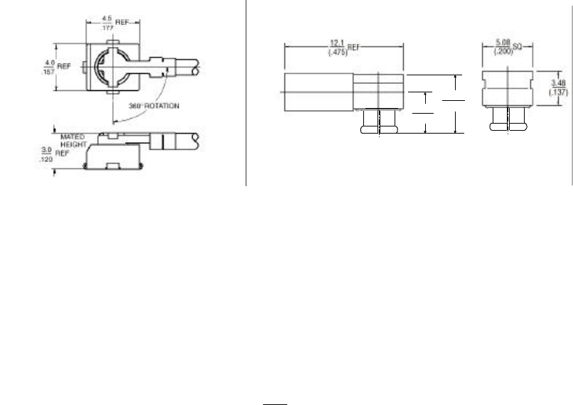
2.2.3 Antenna Connector
Radio frequency (RF) signals from the module to the external, customer-supplied antenna are made
through a surface mount, microminiature snap-on M/A-COM connector (P/N 2367-5002-54). A wide
variety of compatible mating connectors are available. Pigtail assembly (P/N 9960-2100-24), and the
inter-series cable assembly (P/N 9960-4100-XX) from M/A-COM are two options using pre-
assembled cables. The cost of these cables varies with quantity and connector type. Another mating
option is a right angle crimp jack from M/A-COM that uses standard RG-type coaxial cable. Custom
cables assemblies can be then be manufactured to indvidual requirements using standard off-the-shelf
coaxial cable and mating connectors (TNC, SMA, etc.) with
either RG-178 (P/N 2338-5001-10) or RG-316 (P/N 2338-5002-10) size M/A-COM connectors. The
cost of the crimp connector alone is approximately $1.50 USD in quantities of 10,000. Physical
dimensions of the two module connector types are shown above. Since the mating connector can
rotate through 360o, the application developer has maximum flexibility for routing the RF coax
assembly. The total height of the mated pair using M/A-COM pre-assembled RF connectors is 0.12
inches. The mated pair height using the right angle crimp jack is approximately 0.290 inches.
2.3 Electrical Performance
Electrical performance parameters are valid only when the terminating impedance at the output of the
antenna connector exhibits a VSWR of less than 2:1 for all phase angles in the frequency band of
operation. High VSWR loads at the antenna connector adversely affect current consumption,
linearity, and power efficiency of the module and may prevent operation or cause internal damage.
The RF performance of the DM-15 fully meets the following specifications:
IS-136 TDMA Cellular mode – Per IS-137 specification
553 AMPS Cellular mode – Per IS-19 specification
CDPD Mode – Per Cellular Digital Packet Data (CDPD) System Specification, Release 1.1,
19 January 1995,
Pigtail Assembly
.152
(3.86)
.223
(5.66)
Right Angle Crimp Jack

14
2.4 Mobile Station Power Class
The module is able to operate in several modes and different output power levels. Typical
applications require output power levels similar to those in a handheld cellular phone (600 mW
nominal) which is considered a power class IV unit for dual mode operation. It is possible to increase
the output power level to that of a class I unit (4 W nominal) during the 5 second analog burst data
ode. Table 2.4-1 below shows the nominal output power levels (Effective Radiated Power, assuming
an antenna system gain of 1 dBd (2.5 dBd antenna gain with 1.5 dB cable loss)).
Table 2.4-1: Mobile Station Nominal Power Levels
Mobile Station Power Level (dBW)
01234567 8 9 10
Class I, AMPS 6 2 -2 -6 -10 -14 -18 -22 -22 -22 -22
Class II, AMPS -2 -2 -2 -6 -10 -14 -18 -22 -27±3-32±4-37±5
Class II TDMA 2 2 -2 -6 -10 -14 -18 -22 -27±3-32±4-37±5
Class IV, TDMA -2 -2 -2 -6 -10 -14 -18 -22 -27±3-32±4-37±5
Class IV, PCS -2 -2 -2 -6 -10 -14 -18 -22 -28±3-33±4-38±5
*Note: Output power levels maintained within range of +2 / -4 dB for PL0-7
Power levels 8-10 are valid for digital mode only, maintained within range of +2 / -6 dB
2.5 Power Consumption
2.5.1 Transmit/Talk Mode
DC current in mA AMPS Mode IS-136 Mode CDPD Mode
Peak 617 590 590600 mWatt
RMS 617 355 355
3 W Burst Peak 1810 - -
2.5.2 Standby Mode
DC current in mA AMPS Mode IS-136 Mode CDPD Mode
RMS 36 15 15
2.5.3 Sleep Mode (Minimum DC Power consumption)
A power down or "sleep mode" is available in which the module is placed in a low power
consumption state under control of the host application. In this mode, the unit consumes
approximately TBD uA of current as measured from the VCC_5V supply input on pin 1 of the system
connector. A logic level "0" on pin 19 of the system connector returns the unit to full operation
although there may be a significant delay while the module reestablishes registration with the cellular
network
2.6 Reliability
2.6.1.1 Overall Reliability
Module reliability performance is a function of the specific module application. Reliability prediction
data will be provided for each customer application.

15
2.6.1.2 30 Pin Connector Reliability
Durability: 200 mating cycles minimum
2.6.1.3 Antenna Connector Reliability
Durability: 50 cycles minimum
2.7 Environmental Requirements
2.7.1.1 Temperature Ranges
The module will function within specified performance parameters over the temperature range of
-40°C to +70°C.
2.7.1.2 Thermal Shock (DUT non-operational)
Temperature Class I : -40° to +85°C
20 thermal shock cycles over temperature profile
2.7.1.3 Moisture Resistance (DUT non-operational)
Maximum temperature 55°C
2.7.1.4 Electrostatic Discharge
ISO 7816-1. Direct discharge to all external connections.
2.7.1.5 Electromagnetic Field Interference
FCC Part 15
2.7.1.6 System Connector Insertion Inversion
System connector is keyed to prevent incorrect installation
2.7.1.7 Mechanical Vibration (DUT operational)
Vibration Class I (Instrument panel mountings)
Vibration Class II.A (Overhead console mountings)
5 Hz to 1000 Hz
Vertical, lateral, & fore/aft axis - 20 hours per axis
2.7.1.8 Mechanical Shock (DUT non-operational)
4 half-sine wave shocks of 20 g’s with 13 msec duration in three mutually perpendicular planes
2.7.1.9 Crash Shock (DUT operational)
1000 G’s with 11 msec duration
16
3 External Control/Interface
3.1 Introduction
DM-15 interfaces with external controlling devices via an RS-232 serial port on the 30-pin system
connector. This section defines the interface protocol between the controlling device and DM-15 over the
serial port. Future versions of this document will also include the interface definition between various
external accessories and DM-15 over the accessory connector.
The primary message transport mechanism across the system connector interface uses the AT command
format. However, other transport mechanisms, for example, a packet protocol based messaging
mechanism, may also be supported per customer specifications.
Information about AT commands and responses for various Ericsson products are available in two
formats: (1) AT Command Ensembles, and (2) Product Design Documents. An “AT Command
Ensemble” is a group of AT commands that have a specific purpose such as factory test, mode control,
phonebook management, etc. Product Design Documents specify the subsets of AT commands in
various ensembles applicable to a particular product. A separate “Product Design Document” will be
generated for each product.
The AT command descriptions included in this document are intended only to give an overview of the
command functions available, and are not intended to be adequate for software design purposes. The
appropriate set of AT Ensemble Documents will be provided to the application developer under a
separate non-disclosure agreement as part of the Product Design Document. Note AT*E commands are
Ericsson defined commands that may be used by the customer.
3.1.1 Common AT Command Ensembles
§ C1 Basic AT Syntax and Procedures (Revision B)
§ C2/C/E Control and Identification (Revision A)
§ C9 Mode Management (Revision PC2)
§ C50 Time Independent Escape Sequence (Revision A)
§ C53 Enhanced Mode Management (Revision B)
§ C55 Phonebook Group Management for RTP Phones (Revision B)
§ C56 Microsoft Windows Compatibility (Revision B)
§ C57 Phonebook for DAMPS and WSC Phones (Revision PB2)
§ C58 SMS for DAMPS and WSC Phones (Revision B)
§ C59 Autodialer – Voice Call Control for DAMPS and WCS Phones (Revision B)
§ AC12 Basic Vehicle Handsfree (Revision A)
§ AS51 AMPS Modem with Multi-mode Phone Compatibility (Revision A)
§ AC50 Phone Management PC Software (Revision PB1)
§ S50 First generation IS-135 DAMPS Data/Fax (Revision C)
§ S54 Test Commands for DAMPS Phones (Revision A)

17
Ensemble C2, Control and Identification
AT Command Description
AT Check communication between module and host
ATZ Reset to default configuration
AT&F Set to factory-defined configuration
AT+CGMI
AT+CGMI=? Read module manufacturer identification
AT+CGMM
AT+CMMM=? Read module model identification
AT+CGMR
AT+CGMR=? Read module revision identification
AT* List all supported AT commands
AT*ESIR Read module system interface release
Ensemble C9, Mode Management
AT Command Description
AT+WS46 = <n>
AT+WS46?
AT+WS46=?
Sets the cellular protocol mode
AT*EMSH = <n>
AT*EMSH?
AT*EMSH=?
Configuration mode switch/ handoff indications. If set to on, an unsolicited
result code (ECMSH indication) will be sent when mode switch or hand-off
(cell transition) occurs
AT*EMSO = <n>
AT*EMSO?
AT*EMSO=?
Configuration mode switch indications. If set to on, an unsolicited result
code (ECMSH indication) will be sent only when mode switch occurs
Ensemble C50, Time Independent Escape Sequence
AT Command Description
ATS2 = <n>
ATS2? Escape character value
ATS12 = <n>
ATS12? Escape prompt delay timer value
AT*Q[<n>]
AT*Q? Configure CONNECT <text>
Ensemble C53, Enhanced Mode Management
AT Command Description
AT+CFUN=[<fun>[,<rst>]]
AT+CFUN?
AT+CFUN=?
Set functionality of the module.
AT+CPAS=[n]
AT+CPAS?
AT+CPAS=?
Current activity status of the module.
AT*EPLST=[<mode>][,<mode>]…[,<mode>
]
AT*EPLST?
AT*EPLST=?
Set a prioritized list for scanning and connecting to different systems for a
mobile originated call.
AT*EWS46D=<default>
AT*EWS46D?
AT*EWS46D=?
Configure the default-operating mode of the module.
AT+CPIN=”<old_pin>”,”<new_pin>”
AT+CPIN?
AT+CPIN=?
Configure the Personal Identification Number of the module.
AT+CMEE=[<n>]
AT+CMEE?
AT+CMEE=?
Enable and Disable the reporting of module equipment errors.
AT*ECAM=<onoff>
AT*ECAM?
AT*ECAM=?
Enable and disable the return of on-going call events/status.

18
Ensemble C55, Phonebook Group Management
AT Command Description
AT*ERPGL=<mode>[,<group_index>]
AT*ERPGL=? List the phonebook groups or members of groups.
AT*ERPGM=<mode>,<tag>,<value>[,<tag>
,<value>[….]]
AT*ERPGM=?
Add or delete members of a phonebook group or delete or create a phone
group.
AT*ERPGSO=<mode>,<group_index>[,<ta
g>,<value>[….]]
AT*ERPGSO=?
Set or read the settable options of a phone book group.
Ensemble C56, Microsoft Windows Compatibility
AT Command Description
ATI[<value>]
ATI=? Provide information to Windows to enable a Unimodem modem ID
to be derived.
Ensemble C57, Phone Book for DAMPS and WSC Phones
AT Command Description
AT+CPBS=”<storage>”
AT+CPBS?
AT+CPBS=?
Select phonebook memory storage
AT+CPBR=<index1>[,<index2>][,”<pin>”]
AT+CPBR=? Read phonebook entries
AT+CPBF=”<findtext>”[,”<pin>”]
AT+CPBF=? Find phonebook entries
AT+CPBW=[<index>][,”<number>”[,<type>[
,”<text>”[,”<pin>”]]]]
AT+CPBW=?
Write & delete phonebook entry
AT+CSCS=[”<chset>”]
AT+CSCS?
AT+CSCS=?
Select TE character set
AT*ERERS=[<n>]
AT*ERERS=? Extended information responses
AT+CDNN=”[<id>]”
AT+CDNN?
AT+CDNN=?
Set/Read user name (device nickname)
AT+GSN
AT+GSN=? Request product serial number identification
AT+CIMI
AT+CIMI=? Request international mobile subscriber identification
AT*EMOD
AT*EMOD=? Read module model identifier and description
AT+CMIN
AT+CMIN=? Read mobile identification number
AT*ESCN=<mode>,”<pin>”[,<indexn>][,”<a
sn>”,”<vercode>”[,<send
order>][,"<cc_name>"]]
AT*ESCN=?
Read/set calling card parameters
AT*ERCF=<mode>,”<pin>”,<indexn>,[<flow
1>,<flow2>,<flow3>,<flow4>,<flow5>]
AT*ERCF=?
Read/set calling card flow order
AT*ECDF=<mode>,”<pin>”,<indexn>,
[<dflow1>,<dflow2>,<dflow3>,<dflow4>,<dfl
ow5>]
AT*ECDF=?
Read/set calling card domestic flow order
AT*ECIF=<mode>,”<pin>”,<indexn>,
[<iflow1>,<iflow2>,<iflow3>,<iflow4>,
<iflow5>]
AT*ECIF=?
Read/set calling card international flow order

19
Ensemble C58, SMS for DAMPS and WSC Phones
AT Command Description
AT+CSCA="<sca>",[<type>]
AT+CSCA?
AT+CSCA=?
Set the default message-center address in R-Data messages that carry SMS
messages from the mobile termination.
AT+CUDAH=<type>
AT+CUDAH?
AT+CUDAH=?
Set default user-destination address info of R-Data messages used to carry SMS
Submit messages to the message center.
AT+CSDCA="<tag>"
AT+CSDCA?
AT+CSDCA=?
Set the default call-back alpha tag used in SMS Submit messages sent to the
message center.
AT+CSDCN=<enable>,"<address>",[<
type>]
AT+CSDCN?
AT+CSDCN=?
Set the default call-back number used in SMS Submit messages sent to the
message center.
AT+CSDDA=<message>,[<udheader>
]
AT+CSDDA?
AT+CSDDA=?
Set the default SMS Delivery Ack message sent to the message center with a
SMS DELIVERY ACK sent by the MT in response to a mobile terminated SMS
DELIVER.
AT+CSDDD=<enable>,<type>,<time>,
[<offset>],[<daylight>]
AT+CSDDD?
AT+CSDDD=?
Set the default deferred-delivery time used in SMS Submit messages sent to the
message center.
AT+CSDH=<value>
AT+CSDH?
AT+CSDH=?
Control the presentation of SMS and R-Data header information in the following
SMS result codes: +CSTD, +CSLM, and +CSRM.
AT+CSDM=<index>
AT+CSDM=? Delete a short message stored in the mobile termination.
AT+CSDPI=<enable>,<pres>
AT+CSDPI?
AT+CSDPI=?
Set the default presentation indicator used in SMS Submit messages sent to the
message center.
AT+CSDSH=<smheader>
AT+CSDSH?
AT+CSDSH=?
Set the default short-message header used in SMS Submit messages sent to the
message center. Urgent, privacy, ack, update, etc.
AT+CSDUH=<udheader>
AT+CSDUH?
AT+CSDUH=?
Set the default user-data header of SMS Submit and SMS Manual Ack messages
sent to the message center. Encoding method.
AT+CSDVP=<enable>,<type>,<time>,
[<offset>],[<daylight>]
AT+CSDVP?
AT+CSDVP=?
Set the default validity period used in SMS Submit messages sent to the message
center.
AT+CSLM=[<in>],[<out>],[<hold>],[<c
anned>],["<pin>"]
AT+CSLM=?
List short messages stored in the mobile termination.
AT+CSMA=<index>,[<message>],
[<udheader>],[< res_code>],[<msg_ref
>],[<mc_adrs>],[<da>],[<dsa>]
AT+CSMA=?
Originate an SMS Manual Ack message to the message center.
AT+CSME=<value>
AT+CSME?
AT+CSME=?
Control the coding of messages that contain user data with IRA characters are
reported in the +CSTD result code and the +CSLM, +CSRC, +CSRM information
responses.
AT+CSMH=<index>,["<da>"],[<type>]
AT+CSMH=? Originate, from the Hold Box, an SMS Submit message to the message center.
Optionally, a new destination address < da> parameter can be supplied to send
the message to a party other than the original recipient.
AT+CSMS=<value>
AT+CSMS?
AT+CSMS=?
Select the short-message service to be used by the mobile termination. This
command enables an application to differentiate between a GSM SMS AT
command interface and a DAMPS SMS AT command interface.
AT+CSPC=<value>, “<pin>”
AT+CSPC?
AT+CSPC=?
Control delivery and retrieval of private short messages.
AT+CSRC=<index>
AT+CSRC=? Recall a canned message that the user may originate from the mobile-termination
keypad. The canned message may form the user-data content of an SMS Submit

20
message or an SMS Manual Ack message.
AT+CSRI=<delivery>,[<store>]
AT+CSRI?
AT+CSRI=?
Control delivery of unsolicited SMS result codes and the associated storage of
mobile-terminated short messages.
AT+CSRM=<index>,["<pin>"]
AT+CSRM=? Read a short message stored in the mobile termination.
AT+CSSC=<message>,[<index>],[<ud
header>]
AT+CSSC=?
Store a canned message that the user may originate from the mobile-termination
keypad. The canned message may form the user-data content of an SMS Submit
message or an SMS Manual Ack message.
AT+CSSM="<da>",<message>,[<inde
x>],[<msg_ref>],[<type>],[<udheader>]
,[<smsheader>],[<tag><value>]
AT+CSSM=?
Originate an SMS Submit message to the message center.
AT+CSWH="<da>",<message>,[<inde
x>],[<msg_ref>],[<type>],[<udheader>]
,[<smsheader>],[<tag> <value>],…
AT+CSWH=?
Store an SMS Submit message in the Hold Box within MT memory.
AT*ELSI=[“<pin>”]
AT*ELSI=? List short messages that are saved in the In Box of the mobile termination.
AT*EMSI=<index>
AT*EMSI=? Mark short messages as saved in the In Box of the mobile termination.
AT*EMEMUSED[=<selection>]
AT*EMEMUSED=? Read percentage of memory used by SMS and phonebook.
Ensemble C59, Autodialer – Voice Call Control for DAMPS and WSC
AT Command Description
ATA Answer an incoming voice call.
ATH[<value>] Hang-up a voice call.
ATD <dial_string> [< overdial>][;]
[ATD [<overdial>][;]] Originate a voice call with optional DTMF overdial.
ATD> ["<storage>"]<n>[;] Originate a voice call from the phonebook.
ATD![<data >][;] Hook flash and indicate digital data available.
AT*ERVNOK=<value>
AT*ERVNOK?
AT*ERVNOK=?
When enabled, OK is not returned when a semicolon does not terminate ATD.
This enables autodialers such as ACT! to work correctly.
AT*ERDCC
AT*ERDCC?
AT*ERDCC=?
Tell the module to use the selected internal calling card configuration to make the
next call either with ATD or AT+CDV.
AT+CLCK=”<fac>”,<mode>,[,”<pin>”]
AT+CLCK=? Used to unlock incoming or outgoing call restrictions for the execution of the very
next ATD, AT+CDV or ATA. The AT+CLCK returns to its default value after
issuance of the next ATD, AT+CDV or ATA.

21
3.1.2 IS-136 AMPS/DAMPS Ensembles
IS-136 functionalities are exposed to the external controller based on the following Ericsson AT interface
ensembles: • All Common Ensembles Listed in Section 3.1.1
• S50 First Generation IS-136-350 DAMPS Data/Fax
• S54 Test Commands for DAMPS Phones
• AC12 Basic Vehicle HandsFree
Note: inclusion of this feature in DM-15 is to be determined
• AC50 Phone Management PC Software
• AS51 AMPS Modem with Multimode Phone Compatibility
Note: inclusion of this feature in DM-15 is to be determined
The following table provides brief descriptions of the commands defined in these ensembles:
Ensemble S50, First Generation IS-136-350 DAMPS Data/Fax
AT Command Description
ATA Answer a mobile-terminated call.
ATD Originate a call.
ATE[<value>] Enable and disable echoing of command characters.
ATH Disconnect the call.
ATL[<value>] Speaker volume control - does nothing.
ATM[<value>] Speaker mode – does nothing
ATO[<value>] Return the MT and BMI data parts to Online Data State. It is an async- data
command.
ATQ[<value>] Enable and disable result codes suppression.
ATS0=<value>
ATS0? Enable and disable automatic answer.
ATS3=<value>
ATS3? Define the IA5 character used to terminate command lines.
ATS4=<value>
ATS4? Define the IA5 character used in the header and trailer of MT and BMI responses.
ATS5=<value>
ATS5? Define the IA5 character used to delete the preceding character in a command
line.
ATS6=<value>
ATS6? Pause Before Blind Dialing.
ATS7=<value>
ATS7? Set the maximum number of seconds the BMI DCE will try to set up a connection
with another DCE.
ATS8=<value>
ATS8? Set the number of seconds that the BMI DCE will pause, during dialing, upon
encountering a comma in the dial string.
ATS10=<value>
ATS10? Set the duration of received-line-signal loss that the BMI DCE will tolerate. It is an
async-data command.
ATV=<value> Set the response format: header content, trailer content, and terse or verbose
result codes.
ATX=<value> Enable or disable busy-tone detection.
ATZ[<value>] Hard reset the MT to its default settings, and if a call is active, disconnects the
call.
AT&C[<value>] Set how circuit 109 behaves in response to received line signals.
AT&D[<value>] Set how the MT responds to circuit 108/2 – Data Terminal ready.
AT&F[<value>] Reset the MT and BMI DCE to their default settings.
AT+CBC
AT+CBC?
AT+CBC=?
Store the battery-connection status and the battery-charge level.
AT+CCS?
AT+CCS=? Store the radio-interface V.42 bis compression parameters for the current call.
AT+CGCAP
AT+CGCAP=? Return the BMI’s capabilities.
AT+COS==[<SC>],[<BW>],[<FCS>],[<
PM>] Specify the service to be requested for mobile-originated calls.

22
AT+COS?
AT+COS=?
AT+CQD=<value>
AT+CQD?
AT+CQD=?
Set the number of seconds the BMI and MT will stay connected to each other
without the BMI receiving an AT command.
AT+CRC=<value>
AT+CRC?
AT+CRC=?
Enable and disable cellular result codes.
AT+CSM?
AT+CSM=? Store the values of information elements received in the Service Menu message.
AT+CSQ?
AT+CSQ=? Store a signal-quality measure and BER (Bit Error Rate) for the radio channel to
which the MT is tuned.
AT+CSS?
AT+CSS=? Store the frequency band and SID (System Identification) of the serving system.
AT+CTA=[<EN>],[<BW>],[<FCS>],[<P
M>]
AT+CTA?
AT+CTA=?
Specify the attributes to be requested for mobile-terminated async-data calls.
AT+CTD=[<EN>],[<BW>],[<FCS>],[<P
M>]
AT+CTD?
AT+CTD=?
Specify the attributes to be requested for mobile-terminated DADS calls.
AT+CTF=[<EN>],[<BW>],[<FCS>],[<P
M>]
AT+CTF?
AT+CTF=?
Specify the attributes to be requested for mobile-terminated fax calls.
AT+CTS=[<EN>],[<BW>]
AT+CTS?
AT+CTS=?
Specify the attributes to be requested for mobile-terminated STU-III calls
AT+CTV=[<EN>],[<BW>],[<PM>]
AT+CTV?
AT+CTV=?
Specify the attributes to be requested for mobile-terminated voice calls.
AT+DR=[<value>]
AT+DR?
AT+DR=?
Enable or disable data-compression reporting. It is an async-data command.
AT+DS=[<direction>],[<negotiation>],
[<max_dict>],[<max_string>]
AT+DS?
AT+DS=?
Control V.42 bis compression between the MT and the far-end DCE. It is an
async- data command.
AT+EB=[<selection>],[<timed>],[<dfl_l
ength>]
AT+EB?
AT+EB=?
Control break handling at the MT. It is an async-data command.
AT+EFCS=[<value>]
AT+EFCS?
AT+EFCS=?
Specify whether a 16-bit or 32-bit Frame Check Sequence (FCS) will be used for
V.42 links between the BMI DCE and the far-end DCE. It is an async-data
command.
AT+ER=[<value>]
AT+ER?
AT+ER=?
Enable or disable error-control reporting. It is an async-data command.
AT+ES=[<orig_rqst>],[<orig_fbk>],[<a
ns_fbk>]
AT+ES?
AT+ES=?
Control V.42 error-control negotiation between the BMI DCE and the far-end DCE.
It is an async-data command.
AT+ETBM=[<Tx_buf>],[<Rx_buf>],[<ti
mer>]
AT+ETBM?
AT+ETBM=?
Control the handling of data buffers upon call termination. It is an async-data
command.
AT+FAA=<value>
AT+FAA?
AT+FAA=?
Enable or disable adaptive answer.
AT+FAP=<sub>,<sep>,<pwd>
AT+FAP?
AT+FAP=?
Indicate the capability of the DTE to accept T.30 SUB, SEP, or PWD frames.
AT+FBO=<value>
AT+FBO? Set bit transmission order on the PSTN interface.

23
AT+FBO=?
AT+FBU=<value>
AT+FBU?
AT+FBU=?
Enable or disables HDLC frame reporting.
AT+FCC=[<VR>],[<BR>],[<WD>],[<LN
>],[<DF>],[<EC>],[<BF>],[<ST>],[<JP>
]AT+FCC?
AT+FCC=?
Set the T.30 parameters for the current session.
AT+FIS=[<VR>],[<BR>],[<WD>],[<LN>
],[<DF>], [<EC>],[<BF>],[<ST>],[<JP>]
AT+FIS?
AT+FIS=?
Set the T.30 parameters for the current session.
AT+FCLASS=<value>
AT+FCLASS?
AT+FCLASS=?
Select the service for mobile-originated and mobile-terminated calls.
AT+FCQ=<rq>,<tq>
AT+FCQ?
AT+FCQ=?
Control copy-quality checking and correction.
AT+FCR=<value>
AT+FCR?
AT+FCR=?
Indicate whether or not the DTE can receive fax data.
AT+FCS?
AT+FCS=? Provide the negotiated T.30 parameters for the current session.
AT+FCT=<value>
AT+FCT?
AT+FCT=?
Specifie how long the BMI DCE will wait for a command after it has transmitted or
received a fax page.
AT+FDR
AT+FDR?
AT+FDR=?
Request the BMI DCE receive a page.
AT+FDT
AT+FDT=? Request the BMI DCE transmit a page.
AT+FEA=<value>
AT+FEA?
AT+FEA=?
Enable and disable octet-alignment of EOL markers in received fax data.
AT+FFC=<vrc>,<dfc>,<lnc>,<wdc>
AT+FFC?
AT+FFC=?
Enable and disable mismatch checking and conversion of transmitted fax data.
Checking and conversion shall be disabled.
AT+FFD="<value>"
AT+FFD?
AT+FFD=?
Set the file-transfer diagnostic message sent to the remote fax machine.
AT+FHS?
AT+FHS=? Return a valid, but meaningless value — nominally, the hangup cause for the last
call.
AT+FIE=<value>
AT+FIE?
AT+FIE=?
Specify whether procedure-interrupt requests from the remote fax machine will be
accepted.
AT+FIP[=<value>]
AT+FIP=? Initialize Class-2 parameters to default values.
AT+FKS
AT+FKS=? Disconnect the fax call in an orderly fashion.
AT+FLI="<value>"
AT+FLI?
AT+FLI=?
Set the ID to be used in the T.30 CSI or TSI messages.
AT+FLO=<value>
AT+FLO?
AT+FLO=?
Specify the type of flow control.
AT+FLP=<value>
AT+FLP?
AT+FLP=?
Indicate whether or not the DTE has a document to poll.
AT+FMS=<value>
AT+FMS?
AT+FMS=?
Specify the lowest negotiable speed for a fax call.
AT+FND=<value>
AT+FND?
AT+FND=?
Specify the type of message data being transmitted during a call: standard data or
non-standard data.

24
AT+FNR=<rpr>,<tpr>,<idr>,<nsr>
AT+FNR?
AT+FNR=?
Control the reporting of messages generated during T.30 Phase-B negotiations.
AT+FNS="<value>"
AT+FNS?
AT+FNS=?
Set the content of the non-standard-facilities frame.
AT+FPA="<value>"
AT+FPA?
AT+FPA=?
Set the selective-polling address sent to the remote fax machine.
AT+FPI="<value>"
AT+FPI?
AT+FPI=?
Set the polling ID to be used in the T.30 CIG message.
AT+FPP=<value>
AT+FPP?
AT+FPP=?
Enable or disable the packet protocol.
AT+FPR=<value>
AT+FPR?
AT+FPR=?
Set the data-port rate for fax operations.
AT+FPS=<value>
AT+FPS?
AT+FPS=?
Indicate the end-of-page status.
AT+FPW="<value>"
AT+FPW?
AT+FPW=?
Set the password sent to the remote fax machine.
AT+FRQ=<pgl>,<cbl>
AT+FRQ?
AT+FRQ=?
Set the thresholds that are used for the copy-quality-checking procedure.
AT+FRY=<value>
AT+FRY?
AT+FRY=?
Specify a retry count for partial pages in ECM mode.
AT+FSA="<value>"
AT+FSA?
AT+FSA=?
Set the destination subaddress sent to the remote fax machine.
AT+FSP=<value>
AT+FSP?
AT+FSP=?
Indicate whether or not the DTE wants to be informed when the remote fax
machine has a document to be polled.
AT+GCAP
AT+GCAP=? Return the MT’s capabilities.
AT+GMI
AT+GMI=? Return the MT manufacturer code.
AT+GMM
AT+CMM=? Return the MT model number.
AT+GMR
AT+CMR=? Return the MT software and firmware vintage numbers.
AT+ICF=[<value>]
AT+ICF?
AT+ICF=?
Specify the character framing used at the MT data port.
AT+IFC=[<MT_by_DTE>],[<DTE_by_
MT>]
AT+IFC?
AT+IFC=?
Set the flow-control operation of the MT data port.
AT+ILRR=[<value>]
AT+ILRR?
AT+ILRR=?
Enable or disable reporting of the MT data-port rate. It is an async-data command.
AT+IPR=[<rate>]
AT+IPR?
AT+IPR=?
Specify the data-port rate.
AT+MR=[<value>]
AT+MR?
AT+MR=?
Enable or disable reporting of modulation carrier and rate. It is an async-data
command.
AT+MS=[<carrier>],[<automode>],[<mi
n_rate>],
[<max_rate>]
AT+MS?
AT+MS=?
Select modulation, enables or disables automatic negotiation, and sets the
minimum and maximum data rates. It is an async-data command.

25
AT+MV18AM=”<value>”
AT+MV18AM?
AT+MV18AM=?
Set the V.18 answering machine
AT+MV18P=[<probe1>],[<probe2>]…
AT+MV18P?
AT+MV18P=?
Set the order of V.18 probes sent during automoding answer
AT+MV18R=[<value>]
AT+MV18R?
AT+MV18=?
Enable or disables V.18 reporting. It is an async-data command.
AT+MV18S=[<mode>],[<dflt_ans>],[<f
bk_time>],[<ans_msg>]
AT+MV18S?
AT+MV18S=?]
Control V.18 operation.
<CAN>Aborts transmission or reception of a fax page. It is a bi-directional fax command
that appears inband within fax data.
<DC1>
<DC2>Indicates the DTE is ready to receive a fax page. It is a user-to-network fax
command that appears inband within fax data.
<DC3>
<DLE><DLE>Is used for <DLE> transparency. It is a bi-directional fax command that appears
inband within fax data.
<DLE><ETX>Is used for two purposes: to indicate the end of a fax page and to acknowledge a
<CAN>. It is a bi-directional fax command that appears inband within fax data.
<DLE>O Is used as an error marker in fax data delivered to the DTE. It indicates an
overrun in the BMI DCE buffers. It is a network-to-user fax command that appears
inband within fax data.
<DLE><ppm> Indicates the end of a page and the DTE’s intentions for subsequent actions. It is
a user-to-network fax command that appears inband within fax data.
<DLE><SUB> Is used for <DLE><DLE> transparency. It is a bi-directional fax command that
appears inband within fax data.
Ensemble S54, Test Commands for DAMPS Phones
AT Command Description
AT*TEMS
AT*TEMS=? SWITCH TO TEMS COMMAND PROTOCOL
AT*PINT
AT*PINT=? SWITCH TO PINT COMMAND PROTOCOL
AT*ETEST
AT*ETEST=? SWITCH TO ERICSSON TERMINAL PROTOCOL

26
Ensemble AC50, Phone Management PC Software
AT Command Description
AT*ERRLC
AT*ERRLC=? Read last call
AT*ERRCT=<total>,<type>
AT*ERRCT=? Read call totals
AT*ERRGRS=<screen>,[<tag>
<value>],[<tag><value>]….
AT*ERRGRS?
AT*ERRGRS=?
Greeting set
AT*ERMAR=”<pin>”
AT*ERMAR=? Master reset
AT*ERINRES=<mode>,”<pin>”
AT*ERINRES=?
AT*ERINRES?
Incoming call restrictions
AT*EROTRES=<mode>,”<pin>”
AT*EROTRES=?
AT*EROTRES?
Outgoing call restrictions
AT*ERPHLK=<mode>,”<pin>”
AT*ERPHLK=?
AT*ERPHLK?
Power-on phone lock
AT*ERIN=<sound type>[,<call
type>][,”<storage>”,<index>]]
AT*ERIN=?
AT*ERIN?
Ring set for incoming Voice, Data, and Fax
AT*ERIP=<volume>,<sou
nd type>
AT*ERIP=?
Play back sound type
AT+CVIB=<mode>
AT+CVIB=? Set internal vibrator mode
AT*ESMA=<mode>,<option>
AT*ESMA=?
AT*ESMA?
Set message alert sound
AT*ERSAT=<mode>
AT*ERSAT=?
AT*ERSAT?
Setting access tone to alert user when MS is connected to a cellular system
AT*ERSCON=<contrast>
AT*ERSCON=?
AT*ERSCON?
Set the phone contrast. The Contrast function sets the text-to-background
contrast for visibility.
AT*ELAN=”<code>”
AT*ELAN=?
AT*ELAN?
Select which language to use in the interface.
AT*ESAM=<mode>[,<option>]
AT*ESAM=?
AT*ESAM?
Set the answer mode
AT*ERAPD=<mode>,<setting>
[,”<code>”]
AT*ERAPD=?
AT*ERAPD?
Auto area code/prefix dialing
AT*ERSSSD=<mode>,<option>
AT*ERSSSD=?
AT*ERSSSD?
Set and enable/disable speed/super dial mode
AT*ERSAR=<mode>
AT*ERSAR=?
AT*ERSAR?
Set auto retry
AT*COPS=[<mode>[,<form
at>[,”<oper>”]]] Operator selection
AT*ERPRF=<mode>[,<index>,
[”<name>”]]
AT*ERPRF=?
Set or list User Profiles
AT*ERPRFS
AT*ERPRFS=? Profile reset
AT*ERPRAU=<mode>
AT*ERPRAU=?
AT*ERPRAU?
Profile auto activate

27
AT*ERCONDF=<mode>
AT*ERCONDF=?
AT*ERCONDF?
Force MS into Data/fax mode
AT*ERDFS=<mode>
AT*ERDFS=?
AT*ERDFS?
Deactivate the ringer of incoming Data/fax when MS is not connected to a PC
AT*ERMSG=<mode>,<n>
AT*ERMSG=?
AT*ERMSG?
Message alert configuration
3.1.3 CDPD Ensembles
Note: This section is preliminary. Current version of DM-15 does not have CDPD capability.
CDPD functionalities are exposed to the external controller based on the following Ericsson AT interface
ensembles:
§ Common Ensembles (Refer to section 3.1.1)
§ S151 Card Phone commands
§ S152 CDPD test commands (available in future versions of this Document)
§ S154 Card Phone V.80 support

28
Ensemble S151 “Card Phone” commands
AT Command Description
AT*EBPCN Configure Binary Property Change Result Codes.
AT*EPRIVT Configure privacy tone to beep when TDMA voice privacy is requested but not granted.
AT*ECRES Restrict the following TDMA call types:
[<restrict_in>],
[<restrict_out>],
[<restrict_out_cc>],
[<restrict_out_900>],
[<restrict_out_int>],
[<restrict_out_oper>],
[<restrict_out_xspeed>],
[<restrict_out_ldist>],
[<restrict_out_ldist_xspeed>],
[<restrict_out_local_800>],
[<restrict_out_local_800_mem>]
AT*EDORV Treat Unidentified Calls As Data, Fax or Voice.
AT*EHFMICG Set External Handsfree microphone gain.
AT*EHFVOL Set handsfree earpiece volume.
AT*ERCNT Reset counters:
Reset the Total call time counter.
Reset the Total home time counter.
Reset the Analog call counter.
Reset the Analog home counter.
Reset the Digital call counter.
Reset the Digital home counter.
Reset the CDPD Kbyte counter.
AT+CTD Restrict incoming voice calls.
AT+CTF Restrict incoming fax calls.
AT+CTA Restrict incoming async data calls.
AT*ESMM Set minute minder on/off.
AT+CGSN ESN.
AT+WPREG User manually establishes an Internet connection.
AT+WP179 User manually establishes an Internet connection.
AT+WS198 User manually establishes an Internet connection.
AT+WS180 Automatic CDPD power conservation.
AT*ESMM Set minute minder on/off.
AT+WPCHAN CDPD initial channel selection.
AT+WPSPNI Store the CDPD service provider network ID.
AT+WPSPI Service provider lockout.
AT+WS197 Select NEI for registration.
AT+WS198 CDPD initial acquisition timer.
AT+WS45 Set DTE-DCE interface protocol during on-line data mode and on-line command mode.
AT+WPDEST Store the primary CDPD IP address.
AT+WS174 Scan preference.
AT+WS175 CDPD sleep idle time.
AT+WPNEI Configure the network entity identifiers.
AT+WPNEILIST List all network entity identifiers.
AT+WPSTATE Display CDPD status information.
AT+WS46 Set the mode.
AT*TEMS Change to the TEMS command protocol on the system bus.
AT*EPLST Set a priority list for scanning and contact when the phone is placed into multi-scan
mode.
AT+COS Specify the service to be requested for mobile-originated calls.
AT+CRC Enable/disable cellular result codes.
AT+CGMR Request the revision number.
AT+CPWD Change the password.
ATZ Reset the configuration to default parameter values.
AT+CLCK Lock groups of AT commands to user access levels.
AT*EPWERSAVE Configure the power save level of the PC card.
AT*EHFVOL Set the earpiece volume level.

29
AT*ECRAT CDPD channel registration attempt timer.
AT*ECHTO CDPD channel hop time out value.
AT*EIACTO CDPD intra-area cell transfer time out
AT*ECDEL CDPD error logging.
AT*ECDTL CDPD trace logging.
AT*ESEID Store CDPD EID.
AT*ECDEN CDPD encryption.
AT*ECDMCL CDPD minimum carrier level.
AT*ECDCLT CDPD carrier loss timer.
AT*ECDBEC CDPD block error count.
AT*ECDBLERT CDPD block error time threshold.
AT*ECDCGC CDPD congestion count.
AT*ECGCT CDPD congestion count threshold timer.
AT*EMDLPT CDPD MDLP transmit window size.
AT*EMDLPR CDPD receive window size.
AT*EACKT CDPD acknowledgement timer.
AT*ERET CDPD acknowledgement timer.
AT*ERET CDPD retransmission timer.
AT*ECDIRT CDPD identity request retransmission timer.
AT*EMTTEIR CDPD maximum transmission for TEI request.
AT*ECDPRT CDPD packet reassembly timer.
AT*EERCODE Error code return.
AT+IBC The command is used to turn on/off the V.80 In-Band Control Service. Additionally, this
command is used to enable/disable V.24 status reports using V.80.
AT*EV80ISID The action command is used to query the range of <ISID> parameter values accepted
by the DCE. An <ISID> is assigned to each information stream supported by the DCE
with the exception of the V.24 Information Stream
Ensemble S154, Card Phone V.80 Support
AT Command Description
AT+IBC
AT+IBC=?
AT+IBC?
In-band control service
AT*EV801SID V.80 information stream ID values
3.1.4 OEM Module Ensemble
Additional AT commands and responses were developed to meet OEM module customers’ needs. These
functionalities are grouped in five categories: hardware control, 3-watt burst modem over AMPS voice
channel, NAM programming via AT command, miscellaneous, and customer specific.
Hardware Control
AT Command Description
AT*EPSRC Select the PCM clock source
AT*EGPO Set System Connector General Purpose Digital Output
AT*EGPI Read System Connector General Purpose Digital Input
3-Watt Burst Modem over AMPS voice channel
This section describes the AT commands to use burst modem service/features.
Note: This technology is being designed. The AT commands will be available in future versions of this document

30
NAM Programming
AT Command Identification Name Description
AT*NAENC Address Encoding flag Select either TBCD or IA5 encoding
AT*NAKEY A-key Program the value of A-key
AT*NAMID NAM ID Select personal NAM1 or NAM2
AT*NAOLC ACCOLC 4-bit. Overload controls access attempts by the mobile station.
AT*NBAND Band Order Select the bands to be used.
AT*NDSN
see also AT+GSN ESN 32-bit factory set number. Used in the Authentication process
AT*NDSN MS Manufacturer Code Part of ESN
AT*NEMER Emergency numbers Display and enter the emergency number dial strings
AT*NEXAD EX 1-bit Access method. Used to determine if the extended address word is used
in access attempts.
AT*NFTAG Favored Alpha Tag Display and enter the Favored Alpha Tag string.
AT*NGRP User Group Block User Group ID
AT*NHTAG Home Alpha Tag Display and enter the Home Alpha Tag string.
AT*NIPCH First Paging Channel 11-bit. Identify first paging channel at Home
AT*NLCS Last Channel Used flag Display and set/clear the flag controlling the use of the last accessed channel
to start a new scan.
AT*NLOC Local Control Option Enable/disable local control option
AT*NMIN MIN Mobile Station Identification Number (MIN) is a 34-bit MSID sent over the air
interface and is derived from the 10 digit network address used in world zone
1. The AT*NMIN command provides for entering the 10 digit number.
AT*NNTAG Neutral Alpha Tag Display and enter the Neutral Alpha Tag string.
AT*NPRASID Associated Non-Public SID Display and enter the associated PSID or RSID
AT*NPRMCC Mobile Country Code Mobile Country Code may be included in system broadcast information in
support of international applications of IS-136 and international roaming. 3
AT*NPRSID Non-Public PSID/RSID Value 16-bit
AT*NPRSIDT Non-Public PSID/RSID Type PSID or RSID
AT*NPRSOC Non-Public SOC A specific system operator.
AT*NPRTAG Non-Public PSID/RSID
Alphanumeric Name To supply an Alphanumeric PSID/RSID to the user.
AT*NSEL Select Telematics NAM or
Personal NAM for admin. Display and selection of NAM to be administered by subsequent AT*N
commands
AT*NSID Home SID 15-bit. SID is broadcast to provide support for system discrimination
AT*NSOC SOC A specific system operator.
AT*NSPCH Secondary paging channel Display and select the secondary paging channel
Miscellaneous
AT Command Description
AT&V Display Configuration Parameters
AT*ESMUND Display number of Unread SMS Messages
AT*EVMUNRD Display number of Unread Voice Mail Messages
AT*ERSTCT Reset Call Counters and Timers
AT*EKRC Display the KRC Information
AT*EUNSOL Control Unsolicited Messages
AT*NSERV Display current Service State
AT*ECLOG Control Call Logging
AT*ECURTAG Display current Alpha tag
AT*ERD Resume dialing
AT*ESMSHDR Display SMS Header
AT*ECRES Call Restrictions
AT*EFPCS Force Preferred Call State
AT*NAUD Control Audio Paths

31
Customer Specific
AT Command Description
AT*TELU Enter the Telular protocol mode
AT*EBMOPT Set the Win 4 scanning algorithm option and the power limit option
AT+CMGR Read a message from the telematics In-Box.
At+CMTI Unsolicited message. Report the receipt of a burst message from the telematics
call center. The storage space is returned as “” and index parameter is always
reported as zero during telematics mode.
AT+CMT Unsolicited message. Report receipt of message from call center. This message
reports the length of the message and returns the message content.
AT+CNMI Control delivery of unsolicited result codes and associated storage of mobile
terminated messages (CMTI/CMT)
AT+CMGS Write a message to telematiocs out-box and sends the message to the call center
4 Safety
4.1 Exposure to Radio Frequency Signals
This OEM module is a low power radio transmitter and receiver. The module is not designed as or
to be configured as a hand held device. Use as a portable transmitter will require separate FCC
approval for SAR compliance. Typical usage of this OEM module includes:
• remote electrical meter reading
• telematic communication for vehicles
• fixed wireless terminals
Warning:
1. At no time is the antenna to be located closer than 20 centimeters to a normally occupied
location.
2. At no time should an antenna system with greater than 1.0 dB gain be used with this module in
any normally occupied area. The recommended antenna system configuration is a standard
automotive antenna with 2.5 dB antenna gain and 1.5 dB cable loss.
4.2 Module Operation
Safe and efficient use of this module requires a properly terminated antenna. DO NOT operate the
module with a damaged or missing antenna, replace a damaged or missing antenna immediately
otherwise damage to the module may result and could violate FCC regulations. DO NOT operate
this device within 6 inches of a person unless proper shielding from the antenna is installed.
4.3 Posted Facilities
Do not operate this device where posted notices require wireless devices to be turned off.
4.4 Electronic Devices
Most electronic equipment is shielded from RF signals. However, certain electronic equipment may
not be shielded properly against RF signals.
Pacemakers
The Health Industries Manufacturers Association recommends that a minimum separation of six (6) inches be
maintained between a wireless transmitter and a pacemaker to avoid potential interference with the pacemaker.
These recommendations are consistent with the independent research and recommendations of Wireless
Technology Research. Persons with Pacemakers should always keep the antenna/module more than 6 inches
from their pacemaker when the module is on; if you have a reason to suspect that interference is taking place,
turn off the module immediately.
Hearing Aids
32
Some digital wireless devices may interfere with some hearing aids.
Other Medical Devices
If you use any other type of personal medical device in the presence of this transceiver, consult the
manufacturer of your device to determine if it is adequately shielded from external RF energy.
Your physician may be able to assist you in obtaining this information.
4.5 Blasting Areas
To avoid interfering with blasting operations, turn your module off when in a “blasting area” or in
areas posted: “Turn off two-way radio”. Obey all signs and instructions.
4.6 Potentially Explosive Atmospheres
Turn your module off when in any area with a potentially explosive atmosphere and obey all signs and
instructions. Sparks in such areas could cause an explosion or fire resulting in bodily injury or even death.
Areas with a potentially explosive atmosphere are often, but not always, clearly marked. They include such areas
as gasoline stations; below deck on boats; fuel or chemical storage or transfer facilities; vehicles using liquefied
petroleum gas (such as propane or butane); areas where the air contains chemicals or particles, such as grain
dust or metal powders; and any other area where you would normally be advised to turn off your vehicle engine.
4.7 Vehicles
RF signals may affect improperly installed or inadequately shielded electronic systems in motor vehicles. Check
with the manufacturer or its representative regarding your vehicle. You should also consult the manufacturer of
any equipment that has been added to your vehicle.
4.8 For Vehicles Equipped with an Airbag
An airbag inflates with a great force. Do not place objects including both installed or portable wireless equipment
in the area over the airbag or in the airbag deployment area. If in-vehicle wireless equipment is improperly
installed and the airbag inflates, serious injury could result.
4.9 Responsible Use
OEM Manufacturers providing telematic devices for vehicular use are encouraged to incorporate
the following CTIA guidance for safe and responsible wireless phone use into their user’s manuals:
A Guide to Safe and Responsible Wireless Phone Use
TENS OF MILLIONS OF PEOPLE IN THE U.S. TODAY TAKE ADVANTAGE OF THE
UNIQUE COMBINATION OF CONVENIENCE, SAFETY AND VALUE DELIVERED BY THE
WIRELESS TELEPHONE. QUITE SIMPLY, THE WIRELESS PHONE GIVES PEOPLE THE
POWERFUL ABILITY TO COMMUNICATE BY VOICE--ALMOST ANYWHERE,
ANYTIME--WITH THE BOSS, WITH A CLIENT, WITH THE KIDS, WITH EMERGENCY
PERSONNEL OR EVEN WITH THE POLICE. EACH YEAR, AMERICANS MAKE BILLIONS
OF CALLS FROM THEIR WIRELESS PHONES, AND THE NUMBERS ARE RAPIDLY
GROWING.
But an important responsibility accompanies those benefits, one that every wireless phone user
must uphold. When driving a car, driving is your first responsibility. A wireless phone can be an
invaluable tool, but good judgment must be exercised at all times while driving a motor vehicle--
whether on the phone or not.
The basic lessons are ones we all learned as teenagers. Driving requires alertness, caution and
courtesy. It requires a heavy dose of basic common sense---keep your head up, keep your eyes on
the road, check your mirrors frequently and watch out for other drivers. It requires obeying all
traffic signs and signals and staying within the speed limit. It means using seatbelts and requiring
other passengers to do the same.
33
But with wireless phone use, driving safely means a little more. This brochure is a call to wireless
phone users everywhere to make safety their first priority when behind the wheel of a car. Wireless
telecommunications is keeping us in touch, simplifying our lives, protecting us in emergencies and
providing opportunities to help others in need. When it comes to the use of wireless phones, safety
is your most important call.
Wireless Phone "Safety Tips"
Below are safety tips to follow while driving and using a wireless phone, which should be easy to
remember.
1. Get to know your wireless phone and its features such as speed dial and
redial. Carefully read your instruction manual and learn to take advantage of
valuable features most phones offer, including automatic redial and memory.
Also, work to memorize the phone keypad so you can use the speed dial
function without taking your attention off the road.
2. When available, use a hands free device. A number of hands free wireless
phone accessories are readily available today. Whether you choose an installed
mounted device for your wireless phone or a speaker phone accessory, take
advantage of these devices if available to you.
3. Position your wireless phone within easy reach. Make sure you place your
wireless phone within easy reach and where you can grab it without removing
your eyes from the road. If you get an incoming call at an inconvenient time, if
possible, let your voice mail answer it for you.
4. Suspend conversations during hazardous driving conditions or situations.
Let the person you are speaking with know you are driving; if necessary,
suspend the call in heavy traffic or hazardous weather conditions. Rain, sleet,
snow and ice can be hazardous, but so is heavy traffic. As a driver, your first
responsibility is to pay attention to the road.
5. Do not take notes or look up phone numbers while driving. If you are
reading an address book or business card, or writing a "to do" list while driving
a car, you are not watching where you are going. It's common sense. Don't get
caught in a dangerous situation because you are reading or writing and not
paying attention to the road or nearby vehicles.
6. Dial sensibly and assess the traffic; if possible, place calls when you are not
moving or before pulling into traffic. Try to plan your calls before you begin
your trip or attempt to coincide your calls with times you may be stopped at a
stop sign, red light or otherwise stationary. But if you need to dial while
driving, follow this simple tip--dial only a few numbers, check the road and
your mirrors, then continue.
7. Do not engage in stressful or emotional conversations that may be
distracting. Stressful or emotional conversations and driving do not mix--they
are distracting and even dangerous when you are behind the wheel of a car.
34
Make people you are talking with aware you are driving and if necessary,
suspend conversations, which have the potential to divert your attention from
the road.
8. Use your wireless phone to call for help. Your wireless phone is one of the
greatest tools you can own to protect yourself and your family in dangerous
situations--with your phone at your side, help is only three numbers away. Dial
9-1-1 or other local emergency number in the case of fire, traffic accident, road
hazard or medical emergency. Remember that it is a free call on your wireless
phone!
9. Use your wireless phone to help others in emergencies. Your wireless phone
provides you a perfect opportunity to be a "Good Samaritan" in your
community. If you see an auto accident, crime in progress or other serious
emergency where lives are in danger, call 9-1-1 or other local emergency
number, as you would want others to do for you.
10. Call roadside assistance or a special wireless non-emergency assistance
number when necessary. Certain situations you encounter while driving may
require attention but are not urgent enough to merit a call for emergency
services. But you still can use your wireless phone to lend a hand. If you see a
broken-down vehicle posing no serious hazard, a broken traffic signal, a minor
traffic accident where no one appears injured or a vehicle you know to be
stolen, call roadside assistance or other special non-emergency wireless
number.
Careless, distracted individuals and people driving irresponsibly represent a hazard to everyone on
the road. Since 1984, the Cellular Telecommunications Industry Association and the wireless
industry have conducted educational outreach to inform wireless phone users of their
responsibilities as safe drivers and good citizens. As we approach a new century, more and more of
us will take advantage of the benefits of wireless telephones. And, as we take to the roads, we all
have a responsibility to drive safely.