HARRIS TR-423-A2 CM-42 User Manual CM 42 OEM Interface Manua newl
HARRIS CORPORATION CM-42 CM 42 OEM Interface Manua newl
HARRIS >
Contents
- 1. 123101 Manual
- 2. Revised Manual
123101 Manual

Exhibit 8: OEM Interface Manual
12/12/01 11:51 AM ©2001 Ericsson Inc. Page 1 of 16
CM-42
OEM INTERFACE MANUAL

Exhibit 8: OEM Interface Manual
12/12/01 11:51 AM ©2001 Ericsson Inc. Page 2 of 16
CONTENTS – OEM INTERFACE MANUAL
1. CM-42 TRANSCEIVER MODULE OUTLINE DRAWING ........................................................ 3
1.1. MECHANICAL.............................................................................................................................3
1.2. ELECTRICAL ..............................................................................................................................4
1.2.1. ELECTRICAL PERFORMANCE ...............................................................................................4
1.2.2. MOBILE STATION POWER CLASS.........................................................................................5
1.3. POWER CONSUMPTION..............................................................................................................5
2. ABSOLUTE MAXIMUM RATINGS ............................................................................................. 6
3. SAFETY & FCC REQUIREMENTS ............................................................................................. 7
3.1. WARNING: FCC RF EXPOSURE REQUIREMENTS .....................................................................7
3.2. MODULE OPERATION ................................................................................................................7
3.3. OEM LABELING ........................................................................................................................7
3.4. POSTED FACILITIES...................................................................................................................7
3.5. ELECTRONIC DEVICES...............................................................................................................7
3.6. BLASTING AREAS.......................................................................................................................8
3.7. POTENTIALLY EXPLOSIVE ATMOSPHERES ...............................................................................8
3.8. VEHICLES...................................................................................................................................8
3.9. FOR VEHICLES EQUIPPED WITH AN AIRBAG.............................................................................8
3.10. RESPONSIBLE USE .....................................................................................................................8
4. TECHNICAL SPECIFICATIONS ............................................................................................... 12
4.1. INTERFACE CONNECTIONS......................................................................................................13
4.1.1. 40-PIN INTERFACE CONNECTIONS .....................................................................................13
4.1.2. RF INTERFACE CONNECTOR..............................................................................................13
4.1.3. DETAILED SIGNAL DESCRIPTIONS .....................................................................................14
4.1.4. SYSTEM CONNECTOR CMOS INTERFACE LEVELS .............................................................14
4.1.5. SYSTEM CONNECTOR .......................................................................................................14
4.1.6. OVERVIEW .......................................................................................................................14
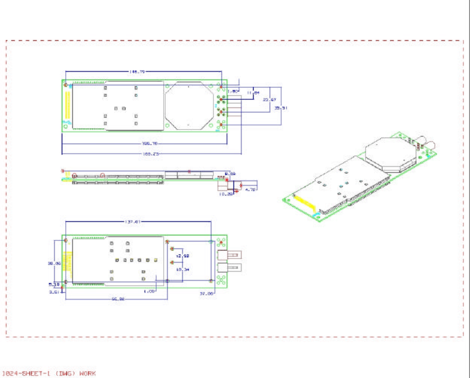
Exhibit 8: OEM Interface Manual
12/12/01 11:51 AM ©2001 Ericsson Inc. Page 3 of 16
1. CM-42 Transceiver Module Outline Drawing
1.1. Mechanical
The CM-42 module has no mechanical elements other that the main PCB assembly. All critical
electronic components are shielded using sheet metal lids and LCP frames to prevent
internal/external electromagnetic interference from degrading the module’s performance and to
prevent the module from interfering with other nearby devices. The following figure shows the
outline drawing for the module. The module is plugged into the fixed mating connector and
secured with eight screws to the standoff components.
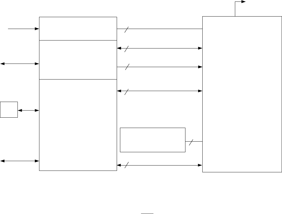
Exhibit 8: OEM Interface Manual
12/12/01 11:51 AM ©2001 Ericsson Inc. Page 4 of 16
1.2. Electrical
The diagram below shows an overview of the electrical interface between the CM-42 module
and a typical application.
CM-42 Electrical Interface
Customer Application
HW
Voltage Regulator
Control Processor
Voice & Data Processing
Ÿ
Echo Cancelling
Ÿ
Noise Cancelling
Ÿ
Audio Power AMP
Ÿ
Data Conversion
DTE
Power
External Audio
Interface
Antenna
User Interface
8
Power & GND
Serial Interface
Wake
Analog Audio Interface
10
1
3
14
4
Optional Simm Device (5)
Reserved (9)
CM-42
Module
PCM Audio Interface
1.2.1. Electrical Performance
Electrical performance parameters are valid only when the terminating impedance at the
output of the antenna connector exhibits a VSWR of less than 2:1 for all phase angles in
the frequency band of operation. High VSWR loads at the antenna connector adversely
affect current consumption, linearity, and power efficiency of the module and may
prevent operation or cause internal damage.
The RF performance of the CM-42 fully meets the following specifications:
• IS-2000 CDMA Cellular mode – Per TIA/EIA-98 specification
• IS-553 AMPS Cellular mode – Per IS-19 specification

Exhibit 8: OEM Interface Manual
12/12/01 11:51 AM ©2001 Ericsson Inc. Page 5 of 16
1.2.2. Mobile Station Power Class
The CM-42 is able to operate in several modes and different output power levels. Applications may
require output power levels similar to those in a handheld cellular phone or higher levels commonly
required when in rural areas. The table below shows the nominal output power levels of the CM42.
(Effective Radiated Power, assuming a maximum antenna system gain of 1 dBi (2.5 dBi antenna
gain with 1.5 dB cable loss)).
Mobile Station Power Level (dBW)
01234567
Class I, AMPS 6 2 -2 -6 -10 -14 -18 -22
Mobile Station Nominal Analog Power Levels
Note: Analog Output power levels maintained within range of +2 / -4 dB for PL0-7
Mobile Station Power Level (dBW)
Lower Limit Upper Limit
Class III, CDMA Band Class 0 -7 dBW (0.2 Watts) 0 dBW (1.0 Watts)
Class II, CDMA Band Class 1 -7 dBW (0.2 Watts) 0 dBW (1.0 Watts)
Mobile Station CDMA Maximum Output Power
1.3. Power Consumption
1.3.1.1 Power Consumption
5.0 V ±10% 12.5 V ±10%Operational Mode Currents
(measurements mA unless otherwise
noted) Average Transient
Peak Average Transient
Peak
Voice Channel PL0 450 650 700 1000
AMPS
Voice Channel PL2 850 920 4.5 -
Standby (waiting for page) 45 -4uA -
Traffic Channel (800/1900MHz) 700/850 1000 4.5 -
CDMA
Standby (waiting for page) 4.0 -4uA -
Table 1: Power Consumption
1.3.1.1.1 Sleep Mode (Minimum DC Power consumption)
A power down mode is available in which the module is placed in a low power consumption state
under control of the host application. In this mode, the unit consumes approximately 110 uA of
current as measured from the VCC_5V supply input and 4 uA of current as measured from the
VCC_12V supply input. To activate this mode, the WAKE signal on pin 12 of the system
connector pulled to a logic level 1 which puts the module into the low power state. The module
will stay in the low power state until the WAKE signal is driven low by an external open collector
transistor in the application circuitry. Turning the external open collector transistor off will cause
the WAKE signal to float high and turn the module off. The WAKE line is tied to VCC_5V through
a 220kΩ pull-up resistor so the sink current in the external open collector transistor is minimal.

Exhibit 8: OEM Interface Manual
12/12/01 11:51 AM ©2001 Ericsson Inc. Page 6 of 16
2. Absolute Maximum Ratings
Parameter Rating Units
Supply voltage
5.0 volts 4.5-5.5 Volts
13.8 volts 11.0-16.5 Volts
Operating temperature -40 to +85 °C
Storage temperature -40 to +85 °C

Exhibit 8: OEM Interface Manual
12/12/01 11:51 AM ©2001 Ericsson Inc. Page 7 of 16
3. Safety & FCC Requirements
3.1. Warning: FCC RF Exposure Requirements
This module is approved for mobile operations only with respect to CFR 47 part 2.1091
and OEM integrators must seek separate approval to satisfy SAR requirements of
2.1093 for operation as a portable device.
Warning: Antenna Installation
1. At no time is the antenna to be located closer than 23 centimeters to a normally
occupied location.
2. At no time should an antenna system with greater than 1.0 dBi gain be used with this
module in any normally occupied area. In an automotive configuration, an antenna
with a 2.5dBi gain and a minimum 1.5 dB of cable loss should be used.
3.2. Module Operation
Safe and efficient use of this module requires a properly terminated antenna. DO NOT
operate the module with a damaged or missing antenna, replace a damaged or missing
antenna immediately otherwise damage to the module may result and could violate FCC
regulations. DO NOT operate this device within 8 inches of a person unless proper
shielding from the antenna is installed.
3.3. OEM Labeling
A label must be affixed to the outside of the end product into which the authorized
module is incorporated, with a statement similar to the following:
This device contains TX FCC ID: XXXXXX (where "XXXXXX" is the FCC ID of the
module).
3.4. Posted Facilities
Do not operate this device where posted notices require wireless devices to be turned
off.
3.5. Electronic Devices
Most electronic equipment is shielded from RF signals. However, certain electronic
equipment may not be shielded properly against RF signals.
Pacemakers
The Health Industries Manufacturers Association recommends that a minimum
separation of six (6) inches be maintained between a wireless transmitter and a
pacemaker to avoid potential interference with the pacemaker. These recommendations
are consistent with the independent research and recommendations of Wireless
Technology Research. Persons with Pacemakers should always keep the
antenna/module more than 6 inches from their pacemaker when the module is on; if
Exhibit 8: OEM Interface Manual
12/12/01 11:51 AM ©2001 Ericsson Inc. Page 8 of 16
you have a reason to suspect that interference is taking place, turn off the module
immediately.
Hearing Aids
Some digital wireless devices may interfere with some hearing aids.
Other Medical Devices
If you use any other type of personal medical device in the presence of this transceiver,
consult the manufacturer of your device to determine if it is adequately shielded from
external RF energy. Your physician may be able to assist you in obtaining this
information.
3.6. Blasting Areas
To avoid interfering with blasting operations, turn your module off when in a “blasting
area” or in areas posted: “Turn off two-way radio”. Obey all signs and instructions.
3.7. Potentially Explosive Atmospheres
Turn your module off when in any area with a potentially explosive atmosphere and
obey all signs and instructions. Sparks in such areas could cause an explosion or fire
resulting in bodily injury or even death.
Areas with a potentially explosive atmosphere are often, but not always, clearly
marked. They include such areas as gasoline stations; below deck on boats; fuel or
chemical storage or transfer facilities; vehicles using liquefied petroleum gas (such as
propane or butane); areas where the air contains chemicals or particles, such as grain
dust or metal powders; and any other area where you would normally be advised to turn
off your vehicle engine.
3.8. Vehicles
RF signals may affect improperly installed or inadequately shielded electronic systems
in motor vehicles. Check with the manufacturer or its representative regarding your
vehicle. You should also consult the manufacturer of any equipment that has been
added to your vehicle.
3.9. For Vehicles Equipped with an Airbag
An airbag inflates with a great force. Do not place objects including both installed or
portable wireless equipment in the area over the airbag or in the airbag deployment
area. If in-vehicle wireless equipment is improperly installed and the airbag inflates,
serious injury could result.
3.10. Responsible Use
OEM Manufacturers providing telematic devices for vehicular use are encouraged to
incorporate the following CTIA guidance for safe and responsible wireless phone use
into their user’s manuals:
Exhibit 8: OEM Interface Manual
12/12/01 11:51 AM ©2001 Ericsson Inc. Page 9 of 16
A Guide to Safe and Responsible Wireless Phone Use
TENS OF MILLIONS OF PEOPLE IN THE U.S. TODAY TAKE ADVANTAGE OF
THE UNIQUE COMBINATION OF CONVENIENCE, SAFETY AND VALUE
DELIVERED BY THE WIRELESS TELEPHONE. QUITE SIMPLY, THE
WIRELESS PHONE GIVES PEOPLE THE POWERFUL ABILITY TO
COMMUNICATE BY VOICE--ALMOST ANYWHERE, ANYTIME--WITH THE
BOSS, WITH A CLIENT, WITH THE KIDS, WITH EMERGENCY PERSONNEL
OR EVEN WITH THE POLICE. EACH YEAR, AMERICANS MAKE BILLIONS OF
CALLS FROM THEIR WIRELESS PHONES, AND THE NUMBERS ARE
RAPIDLY GROWING.
But an important responsibility accompanies those benefits, one that every wireless
phone user must uphold. When driving a car, driving is your first responsibility. A
wireless phone can be an invaluable tool, but good judgment must be exercised at all
times while driving a motor vehicle--whether on the phone or not.
The basic lessons are ones we all learned as teenagers. Driving requires alertness,
caution and courtesy. It requires a heavy dose of basic common sense---keep your head
up, keep your eyes on the road, check your mirrors frequently and watch out for other
drivers. It requires obeying all traffic signs and signals and staying within the speed
limit. It means using seatbelts and requiring other passengers to do the same.
But with wireless phone use, driving safely means a little more. This brochure is a call
to wireless phone users everywhere to make safety their first priority when behind the
wheel of a car. Wireless telecommunications is keeping us in touch, simplifying our
lives, protecting us in emergencies and providing opportunities to help others in need.
When it comes to the use of wireless phones, safety is your most important call.
Wireless Phone "Safety Tips"
Below are safety tips to follow while driving and using a wireless phone, which should
be easy to remember.
1. Get to know your wireless phone and its features such as speed dial and redial.
Carefully read your instruction manual and learn to take advantage of valuable
features most phones offer, including automatic redial and memory. Also, work to
memorize the phone keypad so you can use the speed dial function without taking
your attention off the road.
2. When available, use a hands free device. A number of hands free wireless phone
accessories are readily available today. Whether you choose an installed mounted
device for your wireless phone or a speaker phone accessory, take advantage of
these devices if available to you.
3. Position your wireless phone within easy reach. Make sure you place your
wireless phone within easy reach and where you can grab it without removing your
eyes from the road. If you get an incoming call at an inconvenient time, if possible,
let your voice mail answer it for you.
Exhibit 8: OEM Interface Manual
12/12/01 11:51 AM ©2001 Ericsson Inc. Page 10 of 16
4. Suspend conversations during hazardous driving conditions or situations. Let
the person you are speaking with know you are driving; if necessary, suspend the
call in heavy traffic or hazardous weather conditions. Rain, sleet, snow and ice can
be hazardous, but so is heavy traffic. As a driver, your first responsibility is to pay
attention to the road.
5. Do not take notes or look up phone numbers while driving. If you are reading an
address book or business card, or writing a "to do" list while driving a car, you are
not watching where you are going. It's common sense. Don't get caught in a
dangerous situation because you are reading or writing and not paying attention to
the road or nearby vehicles.
6. Dial sensibly and assess the traffic; if possible, place calls when you are not
moving or before pulling into traffic. Try to plan your calls before you begin your
trip or attempt to coincide your calls with times you may be stopped at a stop sign,
red light or otherwise stationary. But if you need to dial while driving, follow this
simple tip--dial only a few numbers, check the road and your mirrors, then
continue.
7. Do not engage in stressful or emotional conversations that may be distracting.
Stressful or emotional conversations and driving do not mix--they are distracting
and even dangerous when you are behind the wheel of a car. Make people you are
talking with aware you are driving and if necessary, suspend conversations, which
have the potential to divert your attention from the road.
8. Use your wireless phone to call for help. Your wireless phone is one of the greatest
tools you can own to protect yourself and your family in dangerous situations--with
your phone at your side, help is only three numbers away. Dial 9-1-1 or other local
emergency number in the case of fire, traffic accident, road hazard or medical
emergency. Remember that it is a free call on your wireless phone!
9. Use your wireless phone to help others in emergencies. Your wireless phone
provides you a perfect opportunity to be a "Good Samaritan" in your community. If
you see an auto accident, crime in progress or other serious emergency where lives
are in danger, call 9-1-1 or other local emergency number, as you would want
others to do for you.
10. Call roadside assistance or a special wireless non-emergency assistance
number when necessary. Certain situations you encounter while driving may
require attention but are not urgent enough to merit a call for emergency services.
But you still can use your wireless phone to lend a hand. If you see a broken-down
vehicle posing no serious hazard, a broken traffic signal, a minor traffic accident
where no one appears injured or a vehicle you know to be stolen, call roadside
assistance or other special non-emergency wireless number.
Careless, distracted individuals and people driving irresponsibly represent a hazard to
everyone on the road. Since 1984, the Cellular Telecommunications Industry
Association and the wireless industry have conducted educational outreach to inform
wireless phone users of their responsibilities as safe drivers and good citizens. As we
Exhibit 8: OEM Interface Manual
12/12/01 11:51 AM ©2001 Ericsson Inc. Page 11 of 16
approach a new century, more and more of us will take advantage of the benefits of
wireless telephones. And, as we take to the roads, we all have a responsibility to drive
safely.

Exhibit 8: OEM Interface Manual
12/12/01 11:51 AM ©2001 Ericsson Inc. Page 12 of 16
4. Technical Specifications
Mechanical specifications
Maximum length: 155.70 mm
Maximum width: 49.50 mm
Maximum thickness: 18.97 mm
Weight: 68.2 g
Power supply voltage, normal operation VCC_5V VCC_12V
Nominal Voltage: 5.00 Volts 12.5 Volts
Voltage range: 4.50 – 5.50 Volts 11.3 – 13.7 Volts
Power Consumption (Maximum): 1.3 Amp 1.5 Amps
Radio specifications AMPS CDMA (BC-0) CDMA (BC-1)
Frequency range: TX: 824 – 849
RX: 869 – 894 TX: 824 – 849
RX: 869 – 894 TX: 1850-1910
RX: 1930-1990
Maximum RF output power: 3 Watts 1 Watt 1 Watt
Antenna impedance: 50 Ω50 Ω50 Ω
VSWR (Maximum): 2:1 2:1 2:1
Radio specifications
Operating temperature range: -30°C to +70°C: TIA/EIA-2000
-40°C to –30°C: –3dB Degradation beyond –30°C Spec
+70°C to +85°C: –3dB Degradation beyond +70°C Spec
Storage temperature range: -40 0C to +85 0C
Maximum relative humidity: 95% ± 3% at +40 0C
Stationary vibration, random Acceleration spectral density (m2/s2): 0.96 2.88 0.96
Frequency range: 5-10 10-200 200-500
60 min per/axis
Non-stationary vibration, including shock • Shock response spectrum I, peak acceleration:
- 3 shocks in each axis and direction: 300 m/s2, 11 ms
• Shock response spectrum II, peak acceleration:
- 3 shocks in each axis and direction: 1000 m/s2, 6 ms
Bump: Acceleration 250 m/s2
Free fall transportation: 1.2 m
Rolling pitching transportation: Angle: 35 degrees, period: 8s
Static load: 10 kPa
Low air pressure/high air pressure: 70 kPa / 106 kPa
Phone memory
Maximum number of entries stored in the
phone book. 200
Maximum number of SMS messages. 128 entries or a total of 16 kBytes of data.

Exhibit 8: OEM Interface Manual
12/12/01 11:51 AM ©2001 Ericsson Inc. Page 13 of 16
4.1. Interface Connections
4.1.1. 40-pin Interface Connections
Pin Signal Name
Signal Type
Description Dir
1. TBD Dig_2.90 To Be Determined, Do not connect in the application -
2. TBD Dig_2.90 To Be Determined, Do not connect in the application -
3. TBD Dig_2.90 To Be Determined, Do not connect in the application -
4. TBD Dig_2.90 To Be Determined, Do not connect in the application -
5. GND -GND = Ground -
6. GND -GND = Ground -
7. AFMS Analog Audio From Mobile Station O
8. GND -GND = Ground -
9. AGND Analog Analog Reference Should be isolated from GND in application. -
10. ATMS Analog Audio to Mobile Station I
11. Reserved Dig_2.90 No Connect in App. For Non-GSM Modules I
12. WAKE_B -Turns module on/off, ACTIVE LOW I
13. Reserved Dig_2.90 To Be Determined, Do not connect in the application O
14. Reserved Dig_2.90 To Be Determined, Do not connect in the application O
15. Reserved Dig_2.90 To Be Determined, Do not connect in the application O
16. Reserved Dig_2.90 To Be Determined, Do not connect in the application I/O
17. EXTPCMCLK Dig_2.90 External PCM Clock Output O
18. EXTPCMSYNC Dig_2.90 External PCM frame sync O
19. IN/OUT_PCM Dig_2.90 External PCM Audio (Input or Output - Input by default) of the internal PCM codec I/O
20. OUT/IN_PCM Dig_2.90 External PCM Audio (Output or Input – Output by Default) of the internal PCM codec I/O
21. GND -GND = Ground -
22. GND -GND = Ground -
23. VPPFLASH /DCD 12V /Dig_2.90 Flash Programming Voltage of Module,12V/ Data Carrier Detect I/O
24. BUZZER Buzzer output from module, O
25. CTS Dig_2.90 Clear To Send O
26. TBD Dig_2.90 To Be Determined, Do not connect in the application -
27. TD Dig_2.90 Transmitted Data I
28. RTS Dig_2.90 Request To Send I
29. VCC_12V Power Regulated Power I
30. RD Dig_2.90 Received Data O
31. VCC_12V Power Regulated Power I
32. VCC_12V Power Regulated Power I
33. VCC_5V Power Regulated Power I
34. VCC_5V Power Regulated Power I
35. TBD Dig_2.90 To Be Determined, Do not connect in the application -
36. TBD Dig_2.90 To Be Determined, Do not connect in the application -
37. TBD Dig_2.90 To Be Determined, Do not connect in the application -
38. TBD Dig_2.90 To Be Determined, Do not connect in the application -
39. TBD Dig_2.90 To Be Determined, Do not connect in the application -
40. TBD Dig_2.90 To Be Determined, Do not connect in the application -
4.1.2. RF Interface Connector
Radio frequency (RF) signals from the module to the external, customer-supplied antenna are
made through a wide variety of compatible mating connectors. The automobile industry uses the
FAKRA type connectors. The total height of the mated FAKRA RF connectors is 10.5 mm.
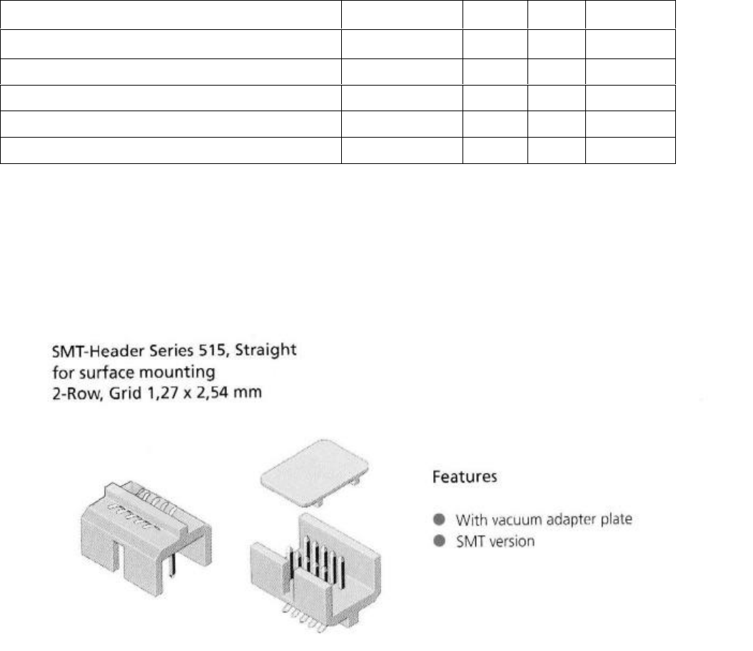
Exhibit 8: OEM Interface Manual
12/12/01 11:51 AM ©2001 Ericsson Inc. Page 14 of 16
4.1.3. Detailed Signal Descriptions
4.1.4. System Connector CMOS Interface Levels
Parameters Test conditions Limits Units
Min. Max.
High level output voltage (IOH= 800 µA) VOH 2.45 2.9 Volts
Low level output voltage (IOL= 800 µA) VOL 00.45 Volts
High-Level Input Voltage (VIH)VIH 1.9 3.1 Volts
Low-Level Input Voltage (VIL)VIL 00.9 Volts
4.1.5. System Connector
4.1.6. Overview
External interfaces to the module are made primarily through a 40-pin, standard 0.050-inch pitch,
ODU header shown below.
Figure 40-pin system connector
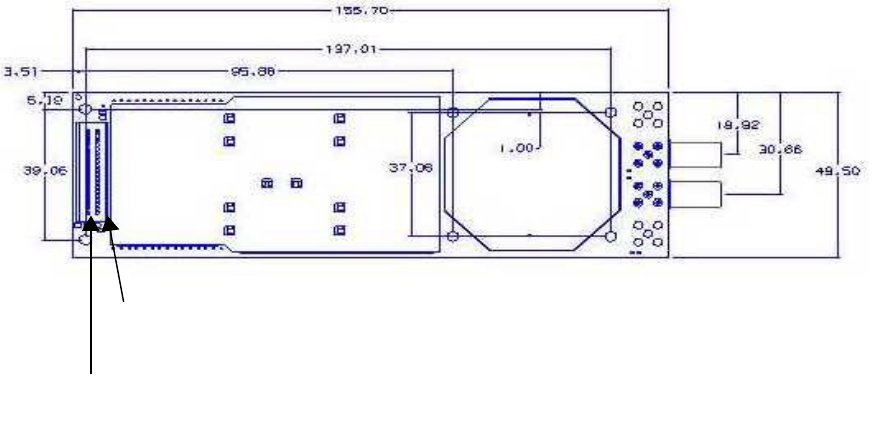
Exhibit 8: OEM Interface Manual
12/12/01 11:51 AM ©2001 Ericsson Inc. Page 15 of 16
Pin #1, Start of odd row
Pin #1, Start of odd row
Pin #2, Start of even row
Figure Pin positions in 40-pin system connector
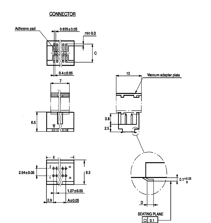
Exhibit 8: OEM Interface Manual
12/12/01 11:51 AM ©2001 Ericsson Inc. Page 16 of 16
Figure 40-pin system connector footprint