HARRIS VMXBA VIDAMAX Base Station User Manual Part 90
Harris Corporation VIDAMAX Base Station Part 90
HARRIS >
Manual

Rhein Tech Laboratories, Inc. Client: M/A-Com, Inc.
360 Herndon Parkway Model: VIDAMAX Base Station
Suite 1400 Standard: FCC Part 90
Herndon, VA 20170 FCC ID: BV8VMXBA
http://www.rheintech.com Report Number: 2006072
57 of 64
Appendix J: Manual
Please refer to the following pages for the installation manual and see also the separate user manual document.

Installation and Configuration Manual
MM-009804-001
May-06
VIDAMAX Base Station
4.9 GHz Broadband Distribution System

MM-009804-001
MANUAL REVISION HISTORY
REVISION DATE REASON FOR CHANGE
- May 2006 Initial Release.
M/A-COM Technical Publications would particularly appreciate feedback on any errors found in this document and
suggestions on how the document could be improved. Submit your comments and suggestions to:
Wireless Systems Business Unit fax your comments to: (434) 455-6851
M/A-COM, Inc. or
Technical Publications e-mail us at: techpubs@tycoelectronics.com
221 Jefferson Ridge Parkway
Lynchburg, VA 24501
CREDITS
NOTICE!
Repairs to this equipment should be made only by an authorized service technician or facility designated by the supplier.
Any repairs, alterations or substitution of recommended parts made by the user to this equipment not approved by the
manufacturer could void the user’s authority to operate the equipment in addition to the manufacturer’s warranty.
NOTICE!
This manual covers M/A-COM, Inc. products manufactured and sold by M/A-COM, Inc.
This device made under license under one or more of the following US patents: 4,590,473; 4,636,791; 5,148,482;
5,185,796; 5,271,017; 5,377,229, 5,377,229; 4,716,407; 4,972460; 5,502,767; 5,146,497; 5,164,986; 5,185,795.
The voice coding technology embodied in this product is protected by intellectual property rights including patent rights,
copyrights, and trade secrets of Digital Voice Systems, Inc. The user of this technology is explicitly prohibited from
attempting to decompile, reverse engineer, or disassemble the Object Code, or in any way convert the Object Code into
human-readable form. NOTICE!
This product conforms to the European Union WEEE Directive 2002/96/EC. Do not dispose of this product in a public
landfill. This product should be taken to a recycling center at the end of its life.
NOTICE!
The software contained in this device is copyrighted by M/A-COM, Inc. Unpublished rights are reserved under the
copyright laws of the United States.
This manual is published by M/A-COM, Inc., without any warranty. Improvements and changes to this manual
necessitated by typographical errors, inaccuracies of current information, or improvements to programs and/or equipment,
may be made by M/A-COM, Inc., at any time and without notice. Such changes will be incorporated into new editions of
this manual. No part of this manual may be reproduced or transmitted in any form or by any means, electronic or
mechanical, including photocopying and recording, for any purpose, without the express written permission of M/A-COM,
Inc.
Copyright © 2006, M/A-COM, Inc. All rights reserved.
2

MM-009804-001
TABLE OF CONTENTS
Page
1 REGULATORY AND SAFETY INFORMATION .............................................................................7
1.1 SAFETY CONVENTIONS...................................................................................................... 7
1.2 REGULATORY......................................................................................................................8
1.2.1 Maximum Permissible Exposure Limits.................................................................... 8
1.2.2 Determining MPE Radius .........................................................................................8
1.2.3 Safety Training Information .................................................................................... 10
2 SPECIFICATIONS.........................................................................................................................11
2.1 GENERAL SPECIFICATIONS............................................................................................. 11
2.2 TRANSMITTER ................................................................................................................... 13
2.3 RECEIVER .......................................................................................................................... 13
3 INTRODUCTION............................................................................................................................14
3.1 ABOUT THIS MANUAL........................................................................................................ 14
3.2 CUSTOMER SERVICE.............................................................................................................. 15
3.2.1 Technical Support................................................................................................... 15
3.2.2 Customer Resource Center....................................................................................15
4 DESCRIPTION...............................................................................................................................16
4.1 VIDAMAX SYSTEM OVERVIEW ........................................................................................... 16
4.2 THE VIDA NETWORK SOLUTION...................................................................................... 16
4.3 THE VIDAMAX NETWORK .................................................................................................... 17
4.4 VIDAMAX NETWORK COMPONENTS/FEATURES ............................................................. 18
4.5 4.9 GHZ VIDAMAX BASE STATION....................................................................................... 20
4.5.1 Summary of Key Features...................................................................................... 21
4.6 VIDAMAX BASE STATION INTERFACES............................................................................. 22
4.6.1 Standard Base Station (AC Powered).................................................................... 22
4.6.2 Special Hardened Base Station (DC Powered)...................................................... 23
4.7 VIDAMAX BASE STATION ANTENNA OPTIONS ........................................................................... 24
5 UNPACKING AND CHECKING EQUIPMENT.............................................................................. 26
5.1 UNPACKING EQUIPMENT ................................................................................................. 26
5.2 INSPECTING AND INVENTORYING EQUIPMENT............................................................ 26
6 PLANNING THE INSTALLATION.................................................................................................27
6.1 ENVIRONMENTAL EVALUATION ...................................................................................... 27
6.2 POLE-MOUNT INSTALLATIONS........................................................................................ 27
6.3 ELECTRICAL POWER ........................................................................................................ 28
6.3.1 AC Power................................................................................................................ 28
6.3.2 DC Power ............................................................................................................... 28
6.4 SITE GROUNDING.............................................................................................................. 28
3

MM-009804-001
TABLE OF CONTENTS
Page
7 INSTALLATION.............................................................................................................................29
7.1 TOOLS AND TEST EQUIPMENT REQUIRED....................................................................29
7.2 CUSTOMER SUPPLIED MATERIALS ................................................................................29
7.3 BEFORE BEGINNING THE INSTALLATION ......................................................................30
7.4 MOUNTING THE BASE STATION ......................................................................................30
7.4.1 Attaching the Mounting Bracket..............................................................................31
7.4.2 Attaching the Base Station to a Pole...................................................................... 32
7.5 POWER CABLES ................................................................................................................32
7.5.1 AC Power................................................................................................................ 32
7.5.2 DC Power ...............................................................................................................32
7.6 GROUNDING STUDS .........................................................................................................32
7.7 NETWORK/DATA CONNECTION....................................................................................... 33
7.8 ANTENNA CONNECTIONS ................................................................................................33
7.8.1 Installing an omni-directional antenna.................................................................... 33
7.8.2 Installing a Directional Antenna.............................................................................. 34
7.9 GPS ANTENNA ......................................................................................................................35
7.9.1 Installing Optional GPS Antenna............................................................................ 35
7.10 RADIO CHASSIS AND CABLING........................................................................................ 36
7.10.1 Attaching Base Station Cables............................................................................... 36
8 OPERATION..................................................................................................................................37
8.1 LOGGING INTO THE VIDAMAX BASE STATION .................................................................37
8.2 TESTING THE VIDAMAX BASE STATION............................................................................37
9 TROUBLESHOOTING AND SERVICING.....................................................................................39
9.1 TUNING AND CALIBRATION PROCEDURE...................................................................... 39
9.1.1 Transmit Frequency Accuracy Calibration.............................................................. 39
9.1.2 Transmit Power Level Calibration...........................................................................39
10 RADIO CHASSIS.................................................................................................................40
11 CABLE FABRICATION.......................................................................................................41
11.1 ETHERNET CABLE PLUG KIT............................................................................................ 41
11.1.1 Tools Required .......................................................................................................41
11.1.2 Cable Selection.......................................................................................................42
11.1.3 Cable Preparation...................................................................................................42
11.1.4 Termination............................................................................................................. 45
11.1.5 Assembly ................................................................................................................46
TABLE OF FIGURES
Page
4

MM-009804-001
TABLE OF FIGURES
Page
Figure 4-1: VIDAMAX Wireless Broadband Video and Data Services ................................................ 16
Figure 4-2: VIDA Network Solution................................................................................................... 17
Figure 4-3: VIDAMAX Broadband Network .....................................................................................18
Figure 4-4: Network diagram of small VIDAMAX system ................................................................... 19
Figure 4-5: VIDAMAX Base Station ...................................................................................................... 20
Figure 4-6: VIDAMAX Base Station Interface Diagram........................................................................22
Figure 6-1: Pole Mounting the VIDAMAX Base Station........................................................................28
Figure 7-1: Mounting the VIDAMAX Base Station on Horizontal or Vertical Poles.............................31
Figure 7-2: Brackets attached to the VIDAMAX Base Station (vertical pole mounting) ...................... 31
Figure 7-3: VIDAMAX Base Station Antenna with External Lightning Protection............................... 34
Figure 7-4: Mounting a Directional Antenna to the VIDAMAX Base Station ......................................35
Figure 13-1: Tyco/Electronics Industrial Circular Ethernet Connector Plug Kit (1738607-2)...........41
Figure 13-2: Cable Preparation ...........................................................................................................43
Figure 13-3: Cable Preparation Continued..........................................................................................44
Figure 13-4: Termination Requirements .............................................................................................45
Figure 13-5: Assembly Detail .............................................................................................................47
TABLE OF TABLES
Page
Table 4-1: Recommended Antenna..................................................................................................... 24
5
MM-009804-001
6
MM-009804-001
1 REGULATORY AND SAFETY INFORMATION
1.1 SAFETY CONVENTIONS
The following conventions may be used in this manual to alert the user to general safety precautions that
must be observed during all phases of operation, service, and repair of this product. Failure to comply
with these precautions or with specific warnings elsewhere in this manual violates safety standards of
design, manufacture, and intended use of the product. M/A-COM, Inc. assumes no liability for the
customer's failure to comply with these standards.
The WARNING symbol calls attention to a procedure, practice, or the like, which,
if not correctly performed or adhered to, could result in personal injury. Do not
proceed beyond a WARNING symbol until the conditions identified are fully
understood or met.
CAUTION
The CAUTION symbol calls attention to an operating procedure, practice, or the
like, which, if not performed correctly or adhered to, could result in a risk of
danger, damage to the equipment, or severely degrade the equipment performance.
The NOTE symbol calls attention to supplemental information, which may improve
system performance or clarify a process or procedure.
The ESD symbol calls attention to procedures, practices, or the like, which could expose
equipment to the effects of Electro-Static Discharge. Proper precautions must be taken
to prevent ESD when handling circuit modules.
The electrical hazard symbol is a WARNING indicating there may be an electrical
shock hazard present.
This symbol indicates the presence of a potential RF hazard.
7
MM-009804-001
1.2 REGULATORY
1.2.1 Maximum Permissible Exposure Limits
DO NOT TRANSMIT with this base station and antenna when persons are within the MAXIMUM
PERMISSIBLE EXPOSURE (MPE) Radius of the antenna. The MPE Radius is the minimum distance
from the antenna axis that ALL persons should maintain in order to avoid RF exposure higher than the
allowable MPE level set by the FCC.
FAILURE TO OBSERVE THESE LIMITS MAY ALLOW ALL PERSONS WITHIN
THE MPE RADIUS TO EXPERIENCE RF RADIATION ABSORPTION, WHICH
EXCEEDS THE FCC MAXIMUM PERMISSIBLE EXPOSURE (MPE) LIMIT. IT IS
THE RESPONSIBILITY OF THE BASE STATION LICENSEE TO ENSURE THAT
THE MAXIMUM PERMISSIBLE EXPOSURE LIMITS ARE OBSERVED AT ALL
TIMES DURING BASE STATION TRANSMISSION. THE BASE STATION
LICENSEE IS TO ENSURE THAT NO BYSTANDERS ARE WITHIN THE RADIUS
LIMITS.
1.2.2 Determining MPE Radius
THE MAXIMUM PERMISSIBLE EXPOSURE RADIUS is unique for each site and is determined
based on the complete installation environment (i.e. co-location, antenna type, transmit power level, etc.).
Determination of the MPE distance is the responsibility of the VIDAMAX user. Calculation of the MPE
radius is required as part of the installation. The Limit for Uncontrolled Exposure Power Density (Pd )
is 10 W/m2 for fixed mounted device.
The M/A-COM 4.9 GHz VIDAMAX Base Station is a fixed mounted radio. After installation and
commissioning, the safe distance from the 9 dBi omni-directional antenna is greater than 20 cm
(8-inches).
1.2.2.1 MPE Calculation for omni-directional Antenna
This MPE Minimum Distance Calculation is based on using a 9 dBi gain omni-directional antenna
mounted directly to the base station RF port.
Basic M/A-COM 4.9 GHz VIDAMAX Base Station specifications:
P: Maximum Peak Conducted Power = 27 dBm
G: Maximum Omni Antenna Gain = 9 dBi
Frequency Range = 4.94 to 4.99 GHz
R: Minimum Distance between User and Antenna = 0.2 m
Equation from FCC:
Pd = P * G / ( 4 * π * R 2 )
Pd = 0.5 W * 7.94 / (4 * 3.1415926 * 0.2 2) = 7.89 W / m2 < 10 W / m2
8

MM-009804-001
The calculation indicates that the minimum 0.2 meter distance between user and the omni-directional
antenna (directly mounted to the base station RF port) is required when operating the M/A-COM 4.9 GHz
VIDAMAX Base Station.
1.2.2.2 MPE Calculation for Directional Antenna
This MPE Minimum Distance Calculation is based on using a directional antenna with more than 9 dBi
antenna gain.
Basic M/A-COM 4.9 GHz VIDAMAX Base Station specifications:
P: Maximum Peak Conducted Power = 27 dBm;
G: Maximum Omni Antenna Gain – Cable Loss = 27 dBi – 1 dB = 26 dBi; (Use numerical GN value
for the calculation ): GN = 10 ^ (G /10)); For G = 26 dBi, GN = 10 ^ (26 /10) = 398
Frequency Range = 4.94 to 4.99 GHz;
Rmin: Minimum Distance between user and antenna to comply with FCC MPE Level (10 W / m2 );
Equation from FCC:
Pd = P * G / ( 4 * π * Rmin 2 )
Rmin = SQRT( 0.5 W * GN / (4 * 3.1415926 * 10 ) )= SQRT ( 3.9789E-3 * GN )
Rmin = 1.26 m, for G =26 (i.e., GN = 398 )
The calculation provides guidelines for users to estimate the minimum safe distance when a high gain
antenna is connected to the M/A-COM 4.9 GHz VIDAMAX Base Station. The user should always keep a
safe distance from antenna greater than 20 cm or SQRT (3.9789E-3 * GN).
The following table lists the minimum distance for Different Effective Antenna Gain Levels (Antenna
Gain – Feeder Cable Loss)
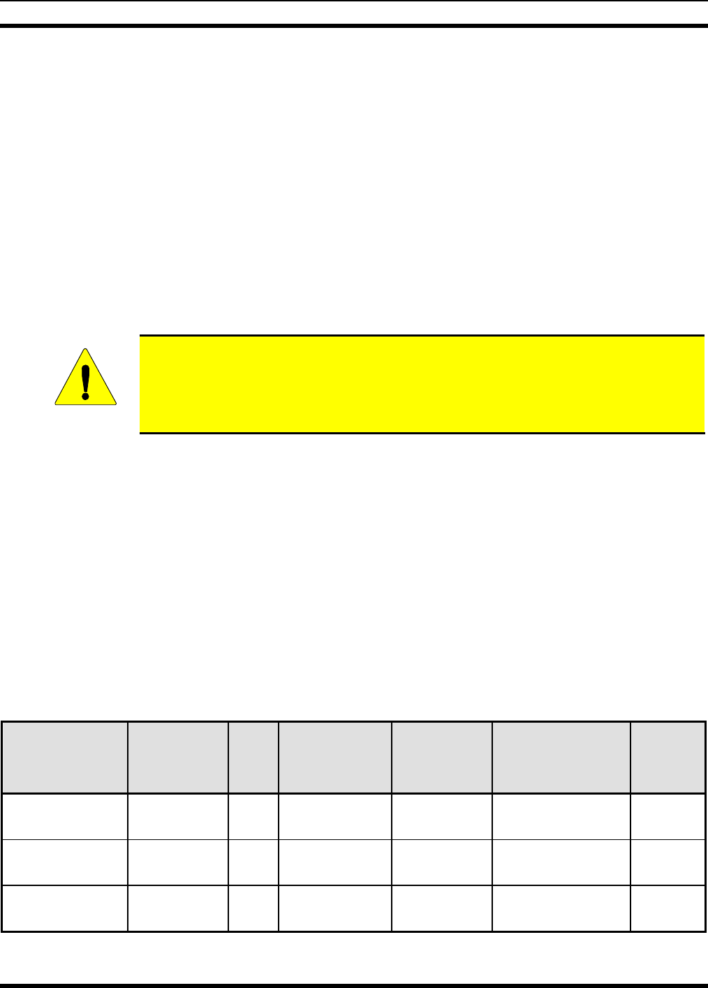
Minimum Safe Distance Calculation Based for Directional Antennas
Effective Antenna
Gain (dBi) Minimum Safe Distance
(Meters) Minimum Safe Distance
(Feet)
< 9 0.20 0.65
10 0.20 0.65
11 0.22 0.73
12 0.25 0.82
13 0.28 0.92
14 0.32 1.04
15 0.35 1.16
16 0.40 1.31
17 0.45 1.47
18 0.50 1.64
19 0.56 1.84
20 0.63 2.07
21 0.71 2.32
22 0.79 2.61
23 0.89 2.92
9
MM-009804-001
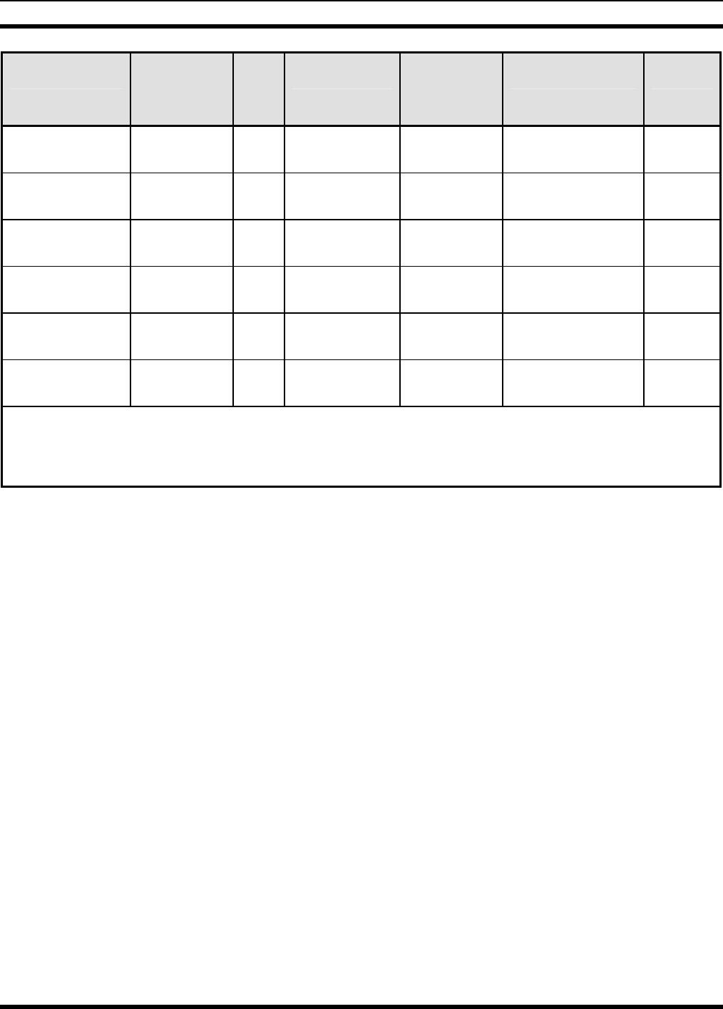
Effective Antenna
Gain (dBi) Minimum Safe Distance
(Meters) Minimum Safe Distance
(Feet)
24 1.00 3.28
25 1.12 3.68
26 1.26 4.13
>26 Reduce Transmit Power is
required by FCC
1.2.3 Safety Training Information
YOUR M/A-COM VIDAMAX BASE STATION GENERATES RF ELECTRO-
MAGNETIC ENERGY DURING TRANSMIT MODE. THIS BASE STATION IS
DESIGNED FOR AND CLASSIFIED AS “OCCUPATIONAL USE ONLY” MEANING
IT MUST BE USED ONLY IN THE COURSE OF EMPLOYMENT BY INDIVIDUALS
AWARE OF THE HAZARDOUS RF ENERGY AND THE WAYS TO MINIMIZE
EXPOSURE. THIS BASE STATION IS NOT INTENDED FOR USE BY THE
“GENERAL POPULATION” IN AN UNCONTROLLED ENVIRONMENT. IT IS THE
RESPONSIBILITY OF THE LICENSEE TO ENSURE THAT THE MAXIMUM
PERMISSIBLE EXPOSURE LIMITS ARE OBSERVED AT ALL TIMES DURING
TRANSMISSION. THE BASE STATION LICENSEE IS TO ENSURE THAT NO
BYSTANDERS COME WITHIN THE RADIUS OF THE LIMITS
When licensed by the FCC, this base station complies with the FCC RF exposure limits when persons are
beyond the MPE radius of the antenna. In addition, your M/A-COM base stations installation complies
with the following Standards and Guidelines with regard to RF energy and electromagnetic energy levels
and evaluation of such levels for exposure to humans:
FCC OET Bulletin 65 Edition 97-01 Supplement C, Evaluating Compliance with FCC Guidelines
for Human Exposure to Radio Frequency Electromagnetic Fields.
American National Standards Institute (C95.1 – 1992), IEEE Standard for Safety Levels with
Respect to Human Exposure to Radio Frequency Electromagnetic Fields, 3 kHz to 300 GHz.
American National Standards Institute (C95.3 – 1992), IEEE Recommended Practice for the
Measurement of Potentially Hazardous Electromagnetic Fields – RF and Microwave.
CAUTION
To ensure that your exposure to RF electromagnetic energy is within the FCC allowable
limits for occupational use, do not operate the base station in a manner that would create
an MPE distance in excess of that allowable by the FCC.
CAUTION
Changes or modifications not expressly approved by M/A-COM Inc. could void the
user’s authority to operate the equipment.
10

MM-009804-001
2 SPECIFICATIONS
2.1 GENERAL SPECIFICATIONS
Physical Characteristics:
Electrical Power: +24 ±3 VDC or
110 VAC +/- 15%, 50-60 Hz
Power Consumption: 60 Watts nominal
Size (H x W x D): 14.5 in. x 8.0 in. x 4.25 in.
(36.8 cm x 20.3 cm x 10.8 cm)
Weight: 13.5 lbs (6.12 kg)
Environmental Specifications
Operating Temperature: -22 - +140 F (-30 to +60 C)
Storage Temperature: -40 - +185 F (-40 to +85 C)
Environmental: NEMA4
Altitude: 15000 ft
System Interfaces
Data Plane: 100Base-FX (RJ-45)
Management: 100Base-FX (RJ-45)
4.9 GHz RF Connector: Type N (F) into 50 ohms
GPS RF Connector: SMA (F) into 50 ohms
Power: 110V VAC
Security Features
Authentication: X.509 Digital Certificate
Authorization: RSA Public Key Encryption
Encryption: DES, 3-DES, AES 128 bit
Network Features
Management: SNMP
Convergence: IPv4 over IEEE 802.3/Ethernet
IEEE 802.3/Ethernet
Configuration: DHCP, TFTP
11

MM-009804-001
PHY Characteristics
PHY: OFDM 256 FFT
Channel Bandwidth: 5 MHz
Modulation Rates: BPSK, QPSK (1/2, 3/4),
16QAM (1/2, 3/4), 64QAM (1/2, 3/4)
Duplexing: Time Division Duplexing (TDD)
Frame Durations: 2.5 msec, 5 msec, 10 msec, 20 msec
CP: 1/32, 1/16, 1/8, 1/4
Throughput: 4-19 Mbps
MAC Characteristics
Duplexing: Time Division Duplexing (TDD)
Service Classes Supported: Real-Time Polling Service (rtPS)
Non-Real-Time Polling Service (nrtPS)
Unsolicited Grant Service (UGS)
Best Efforts (BE)
Payload Header Suppression: Supported
Automatic Repeat Request (ARQ): Supported
Connections/Client: Up to 16
12

MM-009804-001
2.2 TRANSMITTER
Frequency Band: 4940 - 4990 MHz
Channel Step Size: 1 MHz
Channel Bandwidth: 5 MHz
Frequency Stability (-30 to 60 C): 1.5 PPM over temperature range
Output Power into a 50 Ω Load: 0.5 Watts (27 dBm ) Maximum
Power Adjustment: 0.5 – 0.005 W (27 to 7 dBm adjustable with 1 dB
step)
Duty Cycle: 50% Maximum
Emission Designator:
Spurious and Harmonic Emissions: FCC Part 90
PHY: OFDM 256 FFT
Available Modulation Mode: BPSK, QPSK (1/2, ¾), 16QAM (1/2, ¾), 64QAM
(1/2, ¾)
Duplexing: Time Division Duplexing (TDD)
Spectrum Mask: FCC Mask M (90.210)
2.3 RECEIVER
Frequency Band: 4940 - 4990 MHz
Channel Step Size: 1 MHz
Channel Bandwidth: 5 MHz
Frequency Stability: 1.5 PPM
Sensitivity at BER 10E-6:
BPSK -1/2 -96 dBm
QPSK -3/4 -91 dBm
16QAM – 3/4 -85 dBm
Max RX Input Power: -30 dBm
1ST Adjacent Channel Selectivity: 20 dBc Minimum
2nd Adjacent Channel Selectivity: 50 dBc Minimum
13
5M00X7D

MM-009804-001
3 INTRODUCTION
3.1 ABOUT THIS MANUAL
This manual is written for the communications professional responsible for maintaining the VIDAMAX
Base Station equipment installed as part of a VIDAMAX 4.9 GHz Broadband Network.
This manual provides an overview and description of the VIDAMAX Base Station equipment used in the
network, equipment specifications, and instructions for installing VIDAMAX Base Stations and auxiliary
equipment.
14

MM-009804-001
3.2 CUSTOMER SERVICE
3.2.1 Technical Support
M/A-COM’s Technical Assistance Center (TAC) resources are available to help you with overall system
operation, maintenance, upgrades, and product support. TAC is your point of contact when you need
technical questions answered.
Product specialists, with detailed knowledge of product operation, maintenance, and repair, provide
technical support via a toll-free telephone number (in North America). Support is also available through
mail, fax, and e-mail.
For more information about technical assistance services, contact your sales representative, or call the
Technical Assistance Center directly at:
North America: 800-528-7711
International: 434-385-2400
FAX: 434-455-6712
e-mail: tac@tycoelectronics.com
3.2.2 Customer Resource Center
If any part of the system equipment is damaged on arrival, contact the shipper to conduct an inspection
and prepare a damage report. Save the shipping container and all packing materials until the inspection
and the damage report are completed. In addition, contact the Customer Resource Center to make
arrangements for replacement equipment. Do not return any part of the shipment until you receive
detailed instructions from a M/A-COM representative.
Contact the Customer Resource Center at:
North America:
Phone Number: 800-368-3277 (toll free)
Fax Number: 800-833-7592 (toll free)
E-mail: customerfocus@tycoelectronics.com
International:
Asia Pacific: 434-455-9223
Latin America & Middle-East: 434-455-9229
Europe: 434-455-9219
Fax Number: 434-455-6685
E-mail: InternationalCustomerFocus@tycoelectronics.com
15
MM-009804-001
4 DESCRIPTION
The VIDAMAX system delivers public safety grade wireless broadband data services for mission critical
applications, such as video surveillance, broadband hot spots, remote precinct connectivity, and LMR
backhaul.
M/A-COM’s new VIDAMAX broadband network applies the open standard IEEE-based wireless
broadband communications protocol of 802.16 to the 4.9 GHz band, thereby providing true Quality-of-
Service (QoS) while operating on contention-free licensed frequencies.
The VIDAMAX Base Station provides hardened, public safety grade base station infrastructure for M/A-
COM’s 4.9 GHz VIDAMAX broadband network.
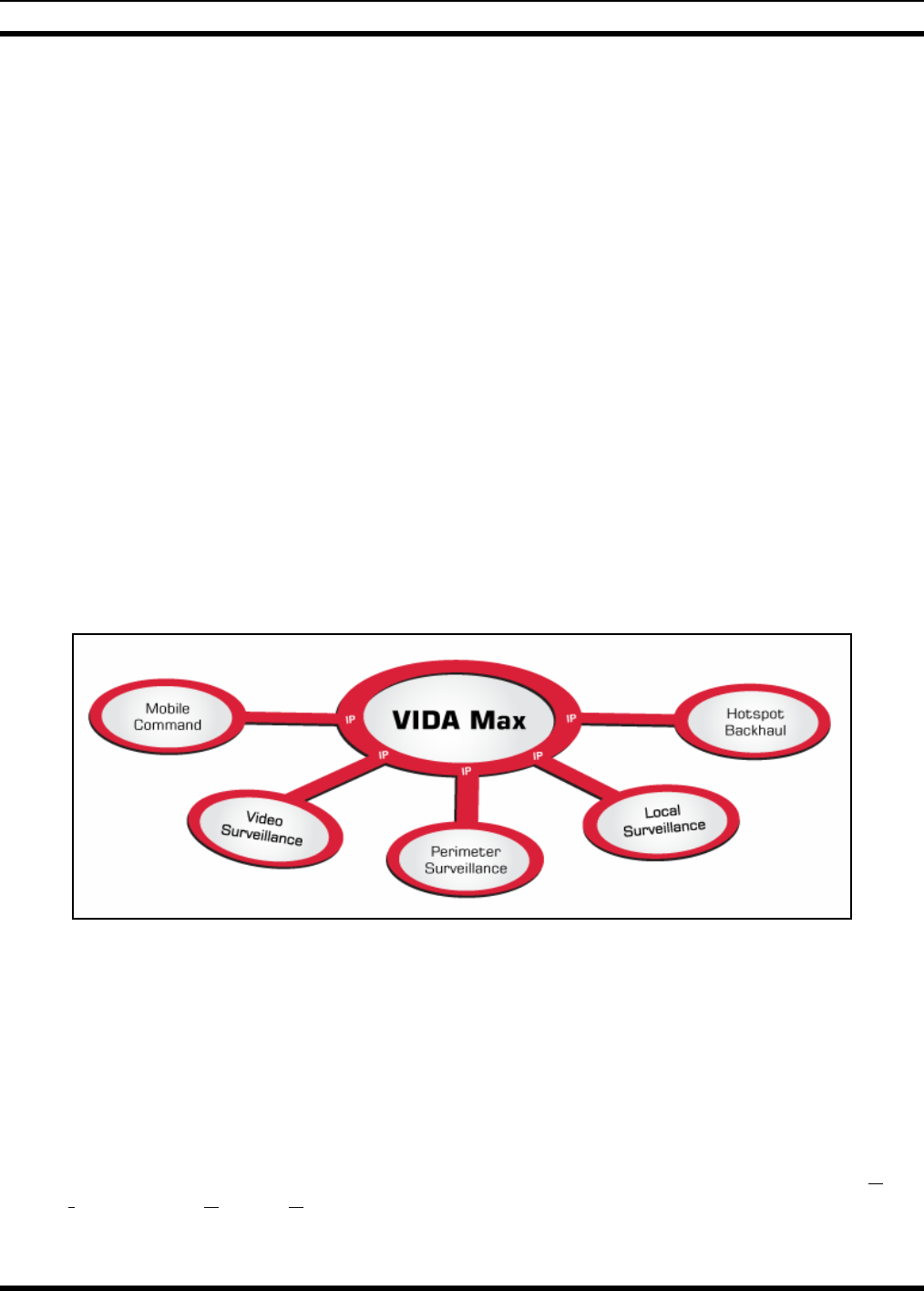
4.1 VIDAMAX SYSTEM OVERVIEW
VIDAMAX provides integrated public safety grade wireless broadband video and data services for mission-
critical applications. VIDAMAX combines the security of the licensed 4.9 GHz public safety frequency
band with robust 802.16 technology to create a true public safety broadband network. With this state-of-
the-art network, public safety customers can implement applications such as streaming video, web
applications, economical licensed LMR backhaul, and other bandwidth intensive applications. Since the
network provides guaranteed Quality of Service (QOS), it is especially suited for applications such as
video surveillance, perimeter control, and mobile command. VIDAMAX is integrated with M/A-COM’s
VIDA network allowing seamless sharing of network management and administration.
Figure 4-1: VIDAMAX Wireless Broadband Video and Data Services
4.2 THE VIDA NETWORK SOLUTION
By leveraging advances in standards-based Information Technology, M/A-COM has developed a unique
IP-based network solution to solve the many challenges that critical communications users are confronted
with. These challenges include delivering different types of information reliably, ensuring technology
does not become quickly obsolete, and being able to acquire equipment from multiple vendors.
VIDAMAX addresses these challenges and is part of a total network solution called VIDA (Voice,
Interoperability, Data, and Access). VIDAMAX is fast, secure and standards based and will allow critical
communications customers to obtain access to information that its users need today and into the future.
16
MM-009804-001
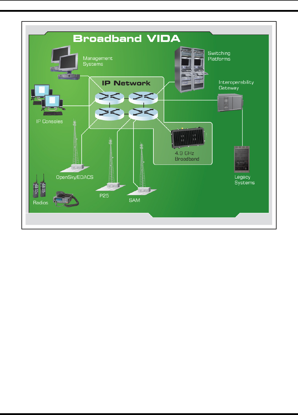
Figure 4-2: VIDA Network Solution
Figure 4-2 depicts a picture of the VIDA Network Solution and how many different communications
systems are built on the solid foundation of a wide-area IP network. This provides an open architecture
for the integration of public safety voice and data airlink protocols including OpenSky, EDACS, and
P25IP. This open architecture enables mission critical communications customers to have one integrated
solution to meet numerous voice and data needs.
4.3 THE VIDAMAX NETWORK
VIDAMAX is the broadband extension of VIDA and as a complete broadband distribution system, can
serve as the airlink to the user, as well as a wireless extension of the core IP network upon which the
VIDA network is based (Figure 4-2).
VIDAMAX integrates the sophisticated Quality-of-Service (QoS) and solid security of the 802.16-2004
(WiMAX) protocol with the licensed protection of the 4.9 GHz public safety band to provide public
safety grade wireless broadband data services for mission critical applications.
17
MM-009804-001
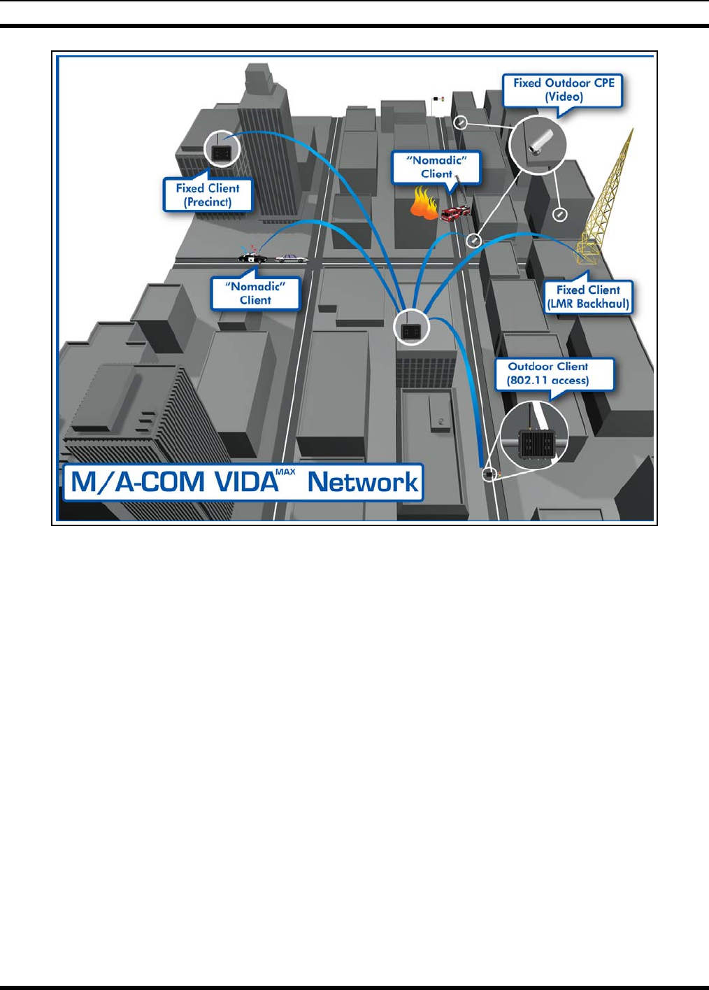
Figure 4-3: VIDAMAX Broadband Network
Figure 4-3 illustrates a typical deployment scenario of the VIDAMAX 4.9 GHz broadband network. It
provides secure, public safety grade broadband services to both fixed and mobile clients. Conceptually,
the system can be seen as extending the enterprise WAN to remote locations using the licensed 4.9 GHz
public safety band. Some common applications for this system include:
• Remote surveillance video
• Mobile broadband access to vehicles (“Hot Spots”)
• Connection of remote precincts to the enterprise and/or VIDA network
• Backhaul of IP based LMR traffic
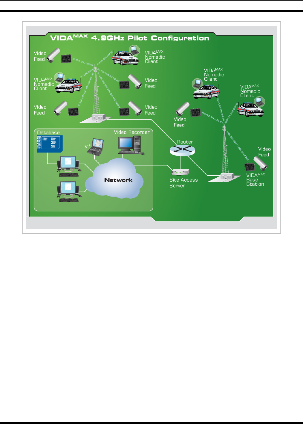
4.4 VIDAMAX NETWORK COMPONENTS/FEATURES
The basic architecture of the 4.9 GHz VIDAMAX network is a point-to-multipoint network. A system
consists of one or more base station(s) and at least one client (Figure 4-3). There are two configurations
of client devices; fixed and mobile. Fixed client devices are usually mounted outdoors with directional
antennas and have a range of up to 10 miles. Mobile clients are vehicle mounted and use an omni-
directional antenna. The range of a mobile client to base station is a few hundred meters.
18
MM-009804-001
Figure 4-4: Network diagram of small VIDAMAX system
The base station implements the 802.16-2004 protocol in a 5 MHz channel, delivering an over-the-air
throughput from 4 to 19 Mbps. All communication over this channel is scheduled by the base station,
with contention slots provided for subscriber stations to request bandwidth. This coordinated scheduling
feature of the protocol provides significant advantages such as:
• Minimizes contention between clients
• Maximizes channel utilization
• Maximizes ability to coordinate frequency usage among users
• Enables guaranteed bandwidth services for critical multimedia applications.
The use of a scheduling protocol also makes the network more resilient to simple denial of service attacks
that can disable other broadband networks.
To allow for great flexibility when designing a network, up to 16 “connections” can be established
between the base station and each client, with a different QoS for each connection. Low priority
processes (such as email) can be mapped to best effort services while high priority processes (such as
19
MM-009804-001
streaming video or LMR backhaul) can be mapped to Unsolicited Grant Services (UGS) to provide
guaranteed throughput.
4.5 4.9 GHz VIDAMAX BASE STATION
The VIDAMAX Base Station provides hardened, public safety grade base station infrastructure for M/A-
COM’s 4.9 GHz VIDAMAX broadband network. The VIDAMAX base station implements the IEEE 802.16-
2004 protocol to deliver an over-the-air throughput from 4 to 19 Mbps. All communication over the
wireless channel is scheduled by the base station, with contention slots provided for subscriber stations to
request bandwidth. Up to 16 “connections” can be established between the base station and each
subscriber in the network, with different QoS for each connection, allowing for great flexibility when
designing a network. Low priority processes (such as email) can be mapped to best effort services while
high priority processes (such as streaming video or LMR backhaul) can be mapped to unsolicited grant
services (UGS) which offer guaranteed throughput. Network convergence is provided in the form of
802.16 classifier rules that ensure network level QoS over the airlink.
Base station configuration and management is provided via a browser interface to M/A-COM’s Unified
Administration System (UAS). The base station additionally supports localized SNMP management for
single/limited site deployments. SNMP attributes are defined in the MIB II, the 802.16 and the M/A-
COM using an open MIB. Base stations may optionally be configured as DHCP and/or TFTP servers.
All subscriber station management can be performed over the air. The VIDAMAX base station provides
strong protection against unauthorized network access through the use of certificates for subscriber
authentication. Authentication keys are distributed using RSA Public Key encryption. The cryptographic
methods provided by the security sub layer use DES, 3-DES, and AES algorithms.
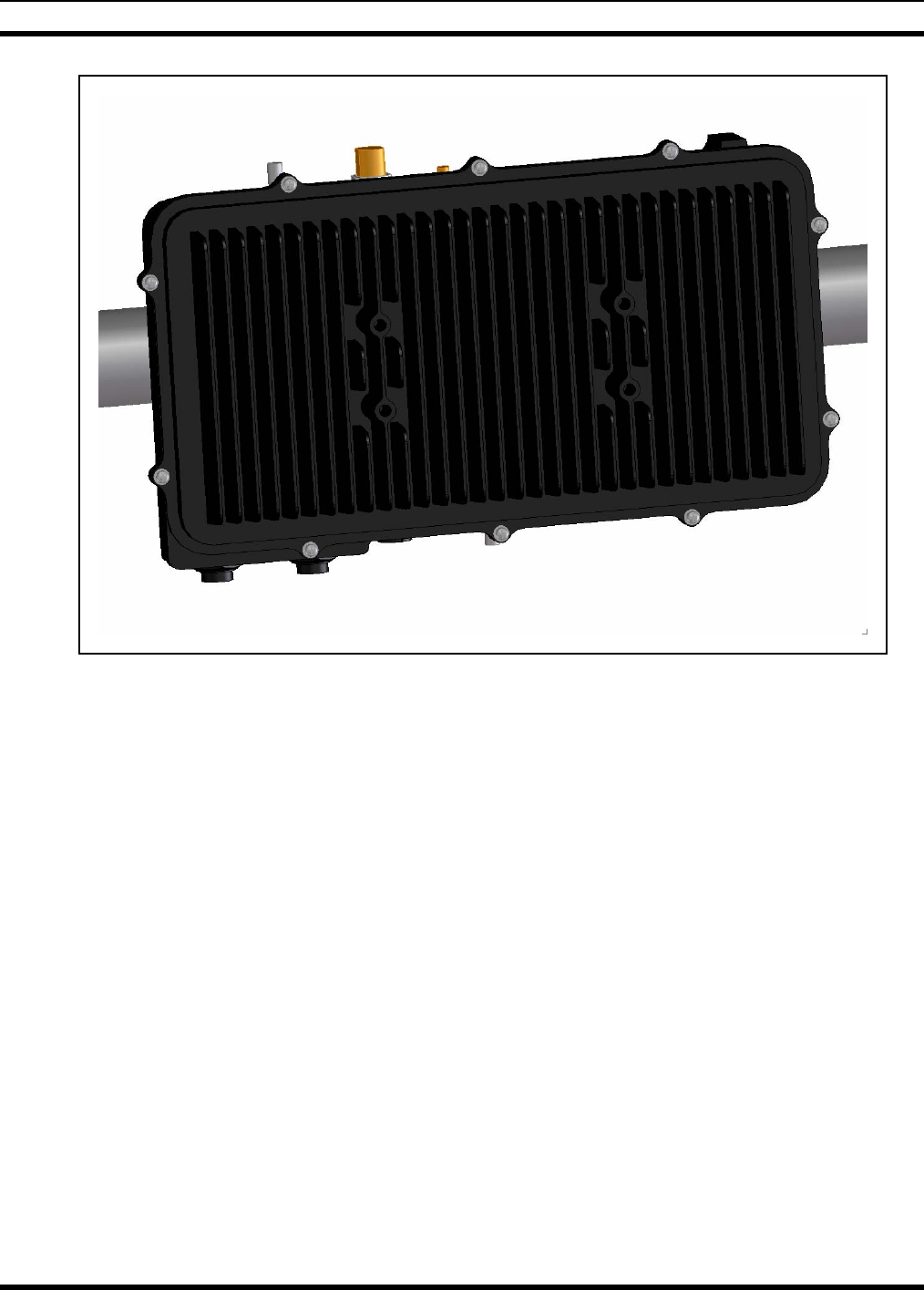
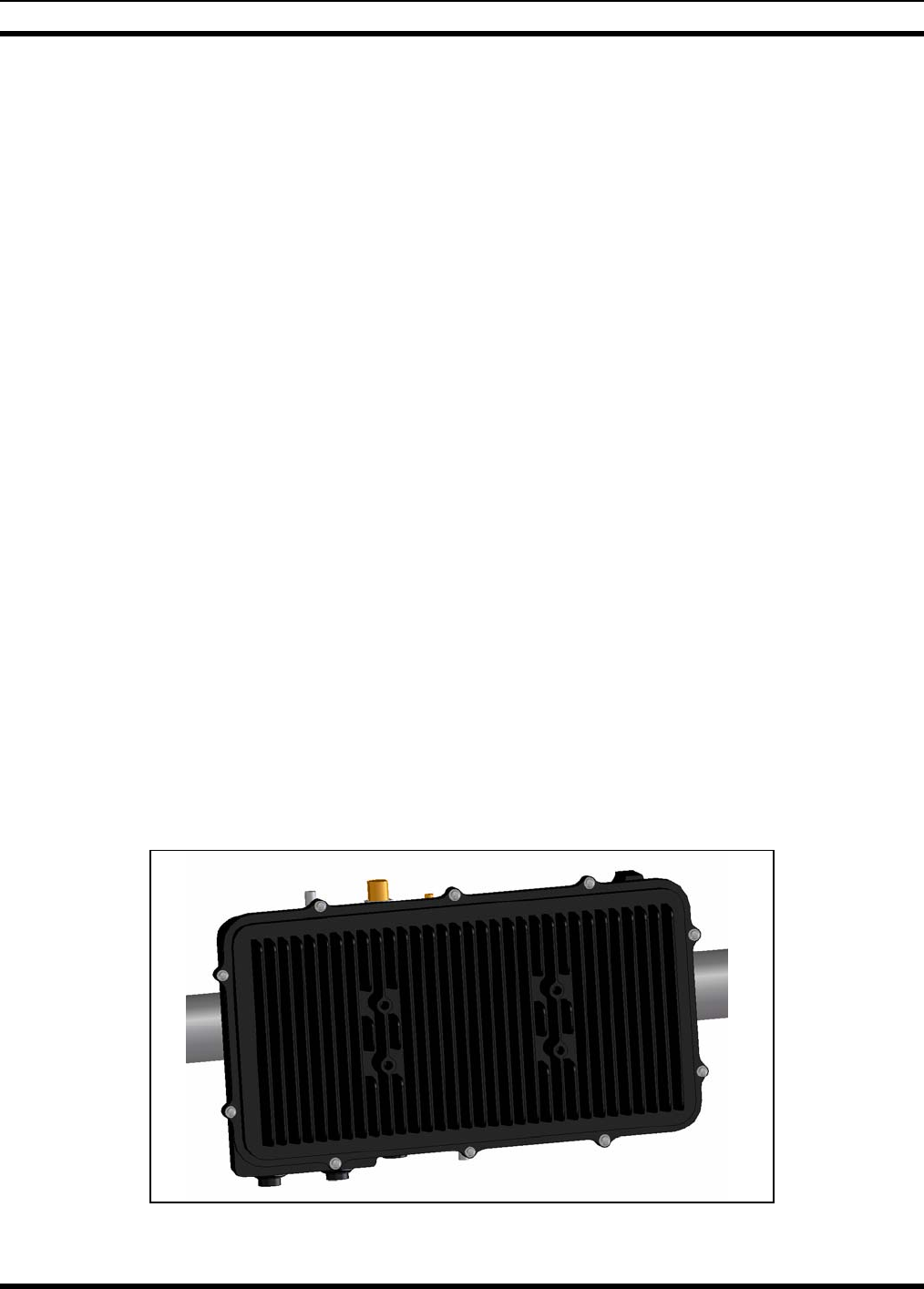
The VIDAMAX Base station is housed in a hardened, outdoor enclosure that satisfies IP66 requirements for
outdoor deployments. The base station is designed with flexible mounting configuration to allow for both
pole mount and fixed structure mounting. To provide for flexible RF deployment configurations, the base
station provides options for (1) direct mounting of an omni-directional antenna on the base station (2)
direct mounting of a directional antenna on the front face of the base station and (3) remote mounting of
an antenna through the connection of an RF cable to the base station. The base station comes in two
power/network configurations: one with 110 VAC power and RJ-45 Gigabit Ethernet configuration and
one with +24 VDC power and 100-BaseFX fiber configuration.
Figure 4-5: VIDAMAX Base Station
20

MM-009804-001
4.5.1 Summary of Key Features
4.5.1.1 Airlink Features
The VIDAMAX Base Station implements the 802.16-2004 protocol to deliver an over-the-air throughput
from 4 to 19 Mbps. All communication over the wireless channel is scheduled by the base station, with
contention slots provided for the VIDAMAX Client to request bandwidth. A protocol with coordinated
scheduling provides significant advantages such as:
• minimizing contention between clients
• maximizing channel utilization
• enabling guaranteed bandwidth services for critical multimedia applications.
The use of a scheduling protocol also makes the network more resilient to simple denial of service attacks
that can disable other broadband networks.
Up to 16 “connections” can be established between the base station and each client in the network, with
different QoS for each connection, allowing for great flexibility when designing a network. Low priority
processes (such as email) can be mapped to best effort services while high priority processes (such as
streaming video or LMR backhaul) can be mapped to unsolicited grant services (UGS) which offer
guaranteed throughput.
4.5.1.2 Network Features
Network convergence is provided in the form of 802.16 classifier rules that ensure network level QoS
over the airlink.
Network management is provided via a browser interface to M/A-COM’s UAS. The base station
additionally supports localized SNMP management using an open MIB. Base stations may optionally be
configured as DHCP and/or TFTP servers. All VIDAMAX Client management can be performed over the
air.
4.5.1.3 Security Features
The VIDAMAX base station provides strong protection against unauthorized network access through the
use of certificates for client authentication. Authentication keys are distributed using RSA Public Key
encryption. The cryptographic methods provided by the security sublayer use DES, 3-DES, and AES
algorithms.
21
MM-009804-001
4.6 VIDAMAX BASE STATION INTERFACES
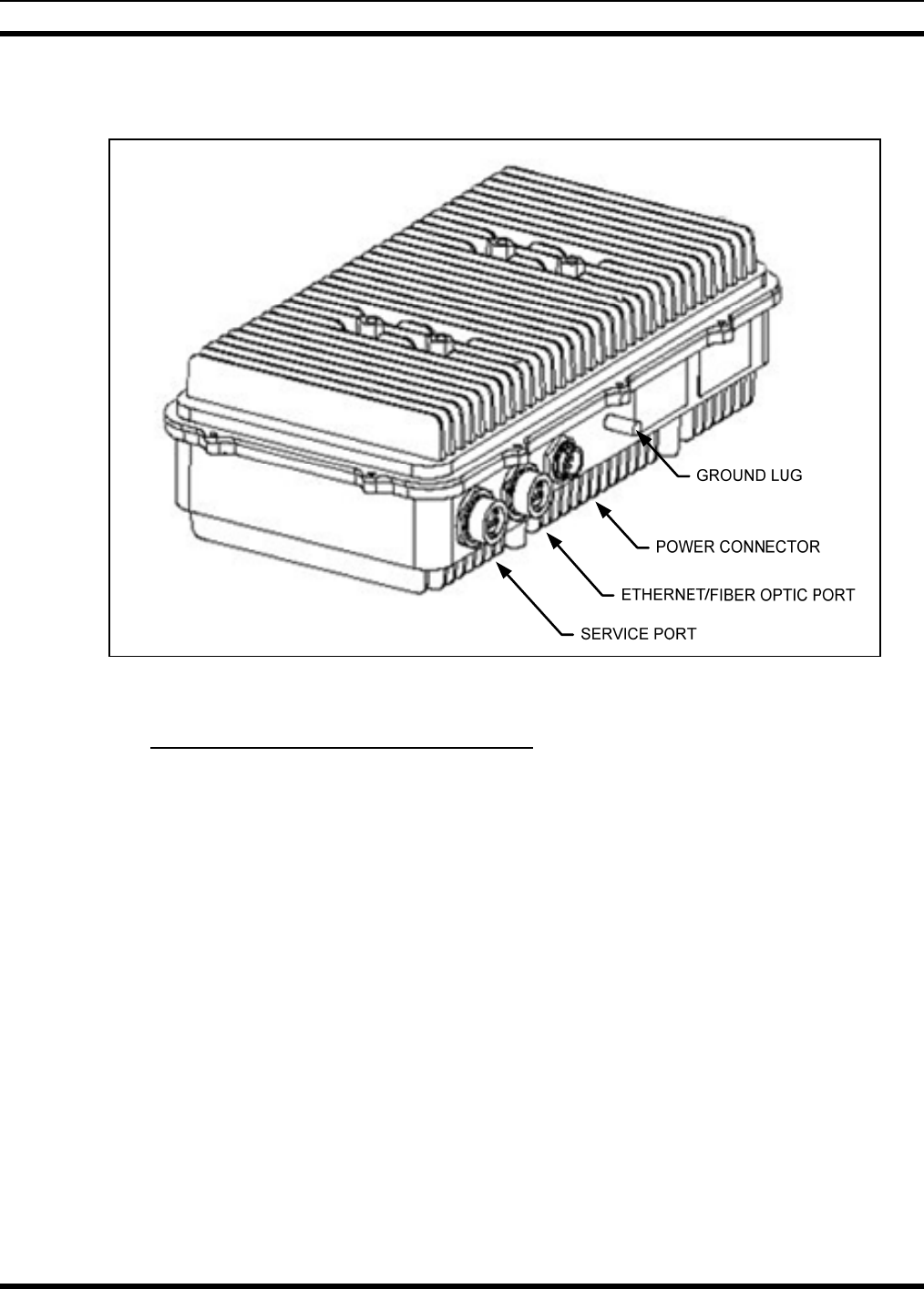
Figure 4-6: VIDAMAX Base Station Interface Diagram
4.6.1 Standard Base Station (AC Powered)
RF Antenna Port:
• Connector: N-type Female
• Impedance: 50 Ohm
110 V AC Power Port:
• Industrialized 3-Pin Connector (Conxall Part No. 4180-3PG-3XX)
DATA Ports:
• Two Industrialized RJ-45 Connectors
• One port for Service only
GPS Antenna Port:
• Connector: SMA Female
• Impedance: 50 Ohm
22

MM-009804-001
4.6.2 Special Hardened Base Station (DC Powered)
RF Antenna Port:
• Connector: N-type Female
• Impedance: 50 Ohm
• Internal Lightning Suppressor
24 V DC Power Port:
• Industrialized 3-Pin Connector (Conxall Part No. 4180-3PG-3XX)
• Internal Lightning Suppressor
DATA Ports:
• LC Industrialized Fiber Optic Connector
• One port for Service only
GPS Antenna Port:
• Connector: SMA Female
• Impedance: 50 Ohm
• External Lightning Suppressor (optional)
23
MM-009804-001
4.7 VIDAMAX Base Station Antenna Options
The VIDAMAX Base Station allows users to choose many different antenna types to meet their application
requirements. Depending on the location and site planning, a directional antenna can significantly extend
the effective coverage area of the base station. For example, one can choose a high gain directional
antenna to effectively cover a long strip of highway, in the meantime avoiding the area further away from
the highway (where coverage is no longer needed) to reduce the total number of base stations. Another
example could be using a 90-degree sectional antenna to effectively cover a town-center area while
avoiding rural regions where no coverage is required. The user can directly mount an omni-directional
antenna to base station RF antenna port. Additionally, four mounting holes are provided on the VIDAMAX
Base Station chassis to allow a directional antenna to be mounted on an optional bracket. Finally, the user
can choose other industry means for mounting a directional or omni-directional antenna separate from
base station. In this case, however, the total length of cable should not exceed 5 feet. Choose high
quality 50-Ohm cable with the lowest loss at 5 GHz.
CAUTION
The four antenna mounting holes on VIDAMAX base station can sustain a pulling
force of 100 mph (160 km/h) sustained wind and survive wind gusts to 136 mph
(220 km/h). It is the user’s responsibility to estimate the force induced by antenna
to ensure the integrity of the product.
Basic Antenna Requirements:
Omni Antenna: Vertical Polarization
9 dBi Maximum Gain
Directional Antenna: Linear Vertical
26 dBi Maximum Gain
(Reduction of Transmitter Power is required if the Effective Maximum Antenna
Gain is greater than 26 dBi.)
The following antennas have been tested and approved for use with the VIDAMAX Base Station:
Table 4-1: Recommended Antenna
Part Number Manufactur
er Gain
(dBi) Polarization Azimuth
Beamwidth
(Degree)
Size Weight
MT-444003 MTI 15 Vertical 120 550 x250x17 (mm^3) 3.3 lbs
(1.5 kg)
MT-466003 (Note 1) MTI 27 Vertical or
Horizontal 3 600x600x51 (mm^3) 11 lbs
(5 kg)
MT-465005 MTI 21 Vertical or
Horizontal 9 305x305x14 (mm^3) 3.3 lbs
(1.5 kg)
24
MM-009804-001
Part Number Manufactur Gain Polarization Azimuth Size Weight
er (dBi) Beamwidth
(Degree)
MT-464003 MTI 15.5 Vertical 90 530x260x11 (mm^3) 5.5 lbs
(2.5 kg)
MT-464002 MTI 16 Vertical 60 350x150x30 3.3 lbs
(1.5 kg)
MT-462002 MTI 9 Vertical Omni 18 in.
(460 mm) 1.3 lbs
(0.6 kg)
MFB49009 MAXRAD 9 Vertical Omni 20.2 in 0.5 lbs
(0.23 kg)
MP24581820PT MAXRAD 20 Vertical 60 384x353x48 (mm^3) 3.9 lbs
(1.8 kg)
MA-WA49-1X Mars 21 Vertical 10.5 305x305x15 (mm^3) 3.3 lbs
(1.5 kg)
Note 1: Based on guidelines from FCC Regulations, the MT-466003 27 dBi Directional Antenna can only be used with a
cable that provides at least 1 dB of insertion loss. It is recommended that this antenna be installed with a minimum of 10
feet of LMR-400-UF antenna feeder cable (Cable Loss = 1.1 dB at 5 GHz). The effective Antenna Gain in this case will
thereby be less than 26 dBi. Also, due to its size, the MT-466003 needs to be individually mounted on the pole.
25
MM-009804-001
5 UNPACKING AND CHECKING EQUIPMENT
Before unpacking, installing or operating the VIDAMAX equipment, read this section of the manual
thoroughly. It contains detailed unpacking and handling instructions, and safety precautions to protect
users and equipment.
5.1 UNPACKING EQUIPMENT
The VIDAMAX equipment may be shipped in separate transit packages. The associated cabling and
accessories for each unit, if any, may also be shipped in separate containers.
When unpacking the equipment, check the contents against the packing list. Contact your M/A-COM
VIDAMAX equipment representative and the carrier if any discrepancies are noted.
Save the shipping cartons and packing materials in case the equipment needs to be shipped
back to the M/A-COM for service.
There are no user serviceable components within the VIDAMAX radio equipment
assemblies. These assemblies contain ESD sensitive components and should only be
serviced by M/A-COM qualified personnel.
5.2 INSPECTING AND INVENTORYING EQUIPMENT
Carefully unpack the equipment and examine each item. If there is any damage to the equipment, contact
the carrier immediately and have their representative verify the damage. If you fail to report the shipping
damages immediately, you may forfeit any claim against the carrier.
CAUTION
After removal from the carton, examine the VIDAMAX equipment for broken,
damaged, loose, or missing parts. Examine the RF connector(s), circular power
connector and ground lug for cracks, bent or damaged threads, or damage to any
paint or seals. If any are noted, contact the M/A-COM Customer Resource Center
immediately. Any unauthorized attempts to repair or modify this equipment will
void the warranty and could create a safety hazard.
26
MM-009804-001
6 PLANNING THE INSTALLATION
6.1 ENVIRONMENTAL EVALUATION
Before installing the VIDAMAX Base Station, the System Engineer and installer should plan the site
selection before attempting to install the base station. Since high frequencies do not readily pass through
trees or buildings, consideration should be given to the following:
• Ensure there are no obstructions (such as buildings or trees) in the radio path between base station
and fixed client units
• Ensure the any future building construction or tree growth will not obstruct the radio path
• Ensure there is sufficient clearance around the Fresnel Zone so there is minimal interference from
obstacles along the radio propagation path
• Ensure the installation adheres to any local building codes and permits
• Ensure sufficient electrical power is available at the installation site
• When using directional antennas, align the base station antenna to maximize the received signal
strength indication (RSSI)
• Ensure area around an omni-directional antenna is clear (at least 30 inches) so as not to distort the
RF pattern
• Locate the base station away from any sources of interference that could degrade the performance
of the base station
• Ensure the base station and fixed clients are within maximum coverage range of reception
• Maximum standard CAT-5 cable length connecting the base station to the Ethernet LAN is 100
meters and maximum antenna cable length is 5-feet
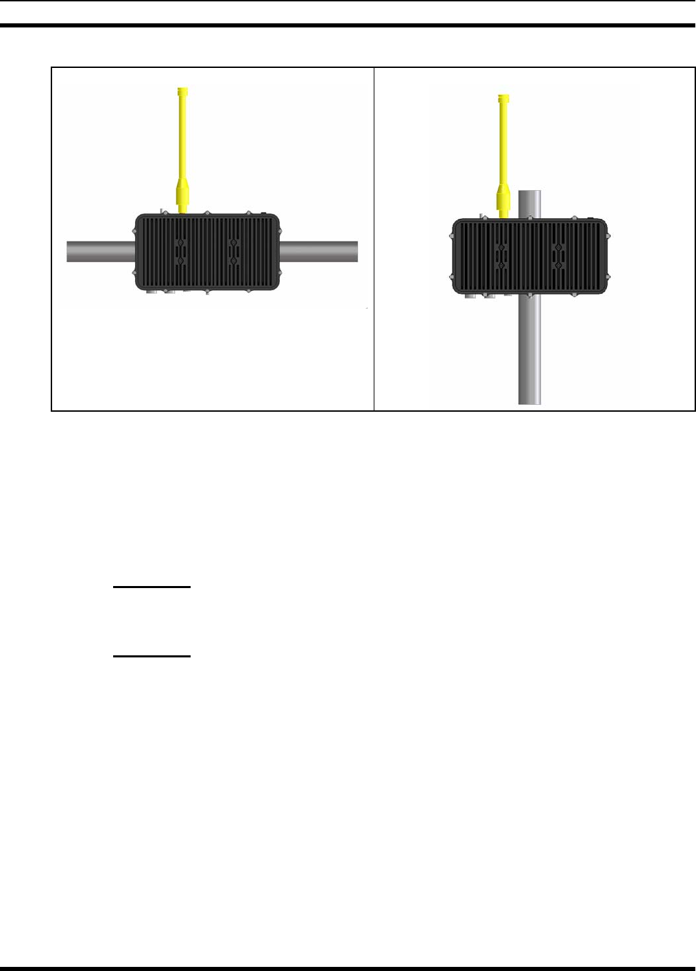
6.2 POLE-MOUNT INSTALLATIONS
The VIDAMAX Base Station is designed to accommodate pole mounting. Typically, pole mounting means
mounting the base station on a light post (horizontally) or telephone pole (vertically) as shown in Figure
6-1. A kit containing two mounting brackets and hardware for attaching the base station to a pole can be
optionally purchased. The bracket accommodates mounting on a pole with a diameter in the range of one
(1) to six (6) inches. The installer must provide straps necessary to secure the base station brackets to the
pole.
CAUTION
When mounting the base station on a pole, the installer must ensure the mounting
bands are strong enough (resistance to rotation) so the base station can withstand 100
mph (160 km/h) sustained wind and survive 136 mph (220 km/h) wind gusts.
27
MM-009804-001
Figure 6-1: Pole Mounting the VIDAMAX Base Station
6.3 ELECTRICAL POWER
There are two configurations of the base station. The AC version is configured to accept 110 VAC power
from standard U.S. utility power distribution. The DC Hardened version of the base station accepts
+24 VDC (negative ground) power from a power supply or battery.
6.3.1 AC Power
An AC powered VIDAMAX base station requires at least 2 amperes of electrical service:
6.3.2 DC Power
A DC powered base station requires a +24-volt (nominal) DC power source. This source must have a
continuous-duty current rating of at least 3 amperes. Refer to Section 2, Specifications for additional
information.
6.4 SITE GROUNDING
Installers should review the recommended grounding procedures in the Site Grounding and Lightning
Protection Guidelines manual, AE/LZT 123 4618/1 and ensure a suitable ground is installed between the
base station ground lug and earth ground. Grounding must also be in compliance with any local and
national electrical codes.
28
MM-009804-001
7 INSTALLATION
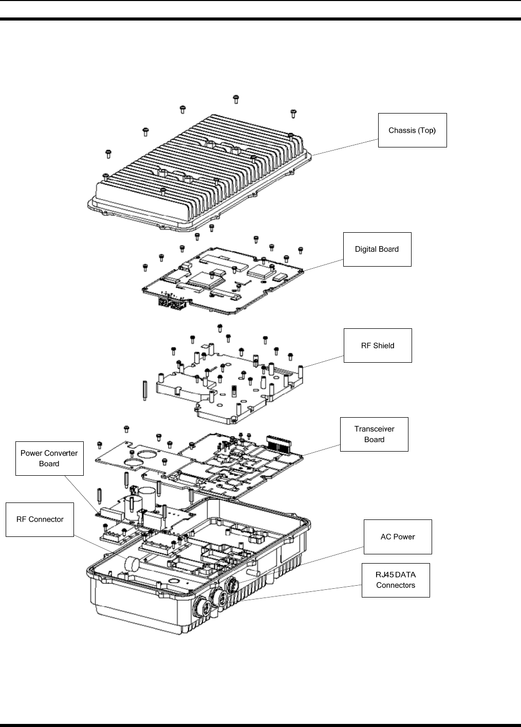
The VIDAMAX Base Station resides in a Die Casting Metal Chassis to meet tough environmental
conditions. The user can choose different antenna types (omni-directional or directional) depending on
the application. It is preferred that the user specifies 50-Ohm low loss (@5GHz) cable with minimum
length (5-feet maximum) between the antenna connector and antenna port on the base station to avoid
further loss of RF power.
The base station is available as either as +24 VDC (hardened) or 110 VAC version. The total power
consumption is less than 60 Watts.
For the AC version, the radio uses weatherproof RJ-45 for connector as data and network connections.
M/A-COM recommends using the DC hardened version of the VIDAMAX base station in the areas that
experience frequent thunderstorms. In this version, weatherproof LC fiber-optic connections are
employed, and lightning protection is internally provided within the base station for the RF antenna and
DC power ports. Additional external lightning protection for the GPS antenna port may optionally be
installed.
Both the RJ-45 and LC fiber-optic connectors achieve weatherproof properties only when
properly mated with M/A-COM approved cabling. For the Service port, the dust cap is to
be installed in normal operation.
7.1 TOOLS AND TEST EQUIPMENT REQUIRED
The following tools and test equipment are recommended for installing and testing the VIDAMAX Base
Station:
• Common hand tools, including screwdrivers, wire cutters, pliers, etc.
• Modular Plug Tool, 3-231652-0 (Tyco/Electronics-AMP)
Includes; Hand Tool, 2-231652-0 and Die Set, 1-853400-0
• Digital Voltmeter (DVM), capable of measuring AC and DC voltage
• Agilent E4440A, PSA series high-performance spectrum analyzer
• Laptop Computer
• Linux operating system
7.2 CUSTOMER SUPPLIED MATERIALS
The customer or designated installer must provide the following:
• Ethernet Cable, length as required, not to exceed 100 ft. (refer to Section 11.1.1 for cable
specifications)
• RF coaxial cable (directional or remotely mounted antenna), i.e. LMR-400 Low loss coaxial cable
29
MM-009804-001
• Pole mounting straps, i.e. Band-It® bands and buckles
• Power source (110 VAC 50/60 Hz or 24 VDC)
• Ethernet connection to network
7.3 BEFORE BEGINNING THE INSTALLATION
Before beginning the installation, collect information from the Site Deployment Order (SDO)
specific to the site access such as:
• Permission to access the site
• Important contact names and telephone numbers
• Location of and directions to the site
• Keys and/or lock combinations to access the site and equipment shelter (if any), or points of
contact to obtain them
• Site entry alarm system pass-codes and/or disable keys
• Information about work practices needed to work safely at the site
Other important information that may or may not be included on the SDO includes:
• Type of mounting—metal pole, wooden pole, tower base, exterior wall, etc.
• Drawing or description of each site showing how the equipment is to be installed
• Applicable inspections completed (pole installation, electrical, local build code, etc.)
7.4 MOUNTING THE BASE STATION
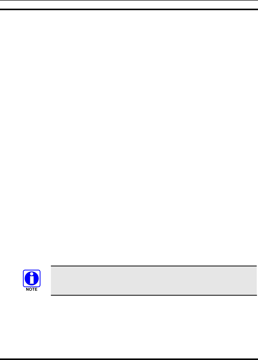
As shown in Figure 7-1, pole-mounting brackets can be installed onto the mounting surface of the base
station so it to be mounted (a) horizontally, for instance, on the arm of a light post, or on a vertical (b)
post. In both cases, two metal straps (not included) are inserted into slots on the brackets and tightened to
the pole using industry strapping equipment.
It is important to mount the base station so that its fins are positioned vertically, as
shown in Figure 7-1 (a) and (b). This gives the base station the best thermal
performance, allowing air to move naturally through the fins
Mounting the base station with the fins vertically also allows the RF antenna port to be in the best
position for mounting the omni-directional antenna, as shown in Figure 7-1.
30
MM-009804-001
a. Horizontal Mounting b. Vertical Mounting
Figure 7-1: Mounting the VIDAMAX Base Station on Horizontal or Vertical Poles
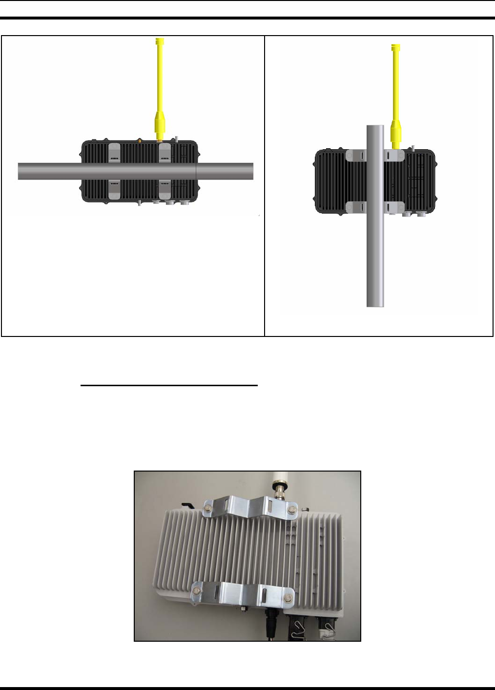
7.4.1 Attaching the Mounting Bracket
1. Orient the brackets so when the base station is mounted on a pole, the fins are vertical. This position
provides the best thermal convection (vertical fins) and shields the multiple connectors from rain.
2. Attach mounting brackets to base station using the flat washer, lock washer, and hex head bolt
included with the brackets. (Ensure lock washer is closest to the bolt’s head.)
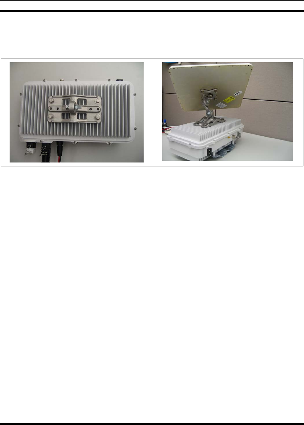
Figure 7-2: Brackets attached to the VIDAMAX Base Station (vertical pole mounting)
31
MM-009804-001
3. The preferable mounting scheme is to have omni-directional antenna pointing straight up.
7.4.2 Attaching the Base Station to a Pole
Strap the base station to pole using Band-It bands and buckles (not supplied). Follow the manufacturer’s
guidelines for proper equipment and techniques.
7.5 POWER CABLES
Power is supplied to the base station through a 3-pin connector. Both AC and DC base stations use the
same power connector, although they require different cables, available for purchase through M/A-COM.
The mating connector is Conxall Multi-Con-X® 3-pin connector #4180-3SG-3xx).
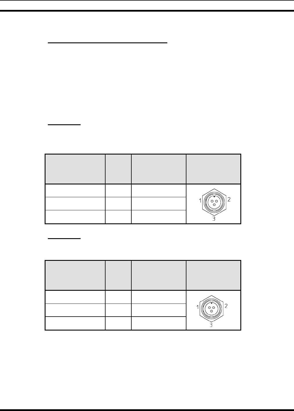
7.5.1 AC Power
The AC powered VIDAMAX Base Station requires 110 VAC, 50-60 Hz power applied to the following
contacts.
Connection Pin Wire Color VIDAMAX Base
Station
Connector
Ground 3 Green
Neutral 2 White/Grey
Hot 1 Black
7.5.2 DC Power
A DC powered VIDAMAX requires 24 ±3 VDC applied to the following contacts:
Connection Pin Wire Color VIDAMAX Base
Station
Connector
+24 VDC (PWR+) 1 Red
Return (PWR-) 2 Black
7.6 GROUNDING STUDS
Mounting studs for grounding the base station are located on two sides of the base station. For safety
purposes, earth ground and lightning protection electrical connections should be made at either location.
32

MM-009804-001
7.7 NETWORK/DATA CONNECTION
The AC version of the base station connects to the network using standard Ethernet RJ-45 protocol. The
DC hardened version connects to the network through a standard LC multimode fiber optic connector.
The proper connection in both cases is on the port that does not have the dust cap installed.
Recommended Ethernet mating connectors:
For AC powered VIDAMAX base station:
• Tyco/Electronics, Industrial Circular Ethernet Connector
Part number: 1738607-2
For DC powered VIDAMAX base station:
• Tyco/Electronics, LC multimode fiber optic connector
Part number: 1828618-1
All connections are weatherproof, and the service port has a dust cap which is normally installed to
provide the sealing. Sealing of all other ports on the base station is provided through mandatory usage
connections.
7.8 ANTENNA CONNECTIONS
The omni-directional antenna should be mounted vertically directly onto the antenna port. There is also a
mounting feature on the base station to support the mounting a directional antenna.
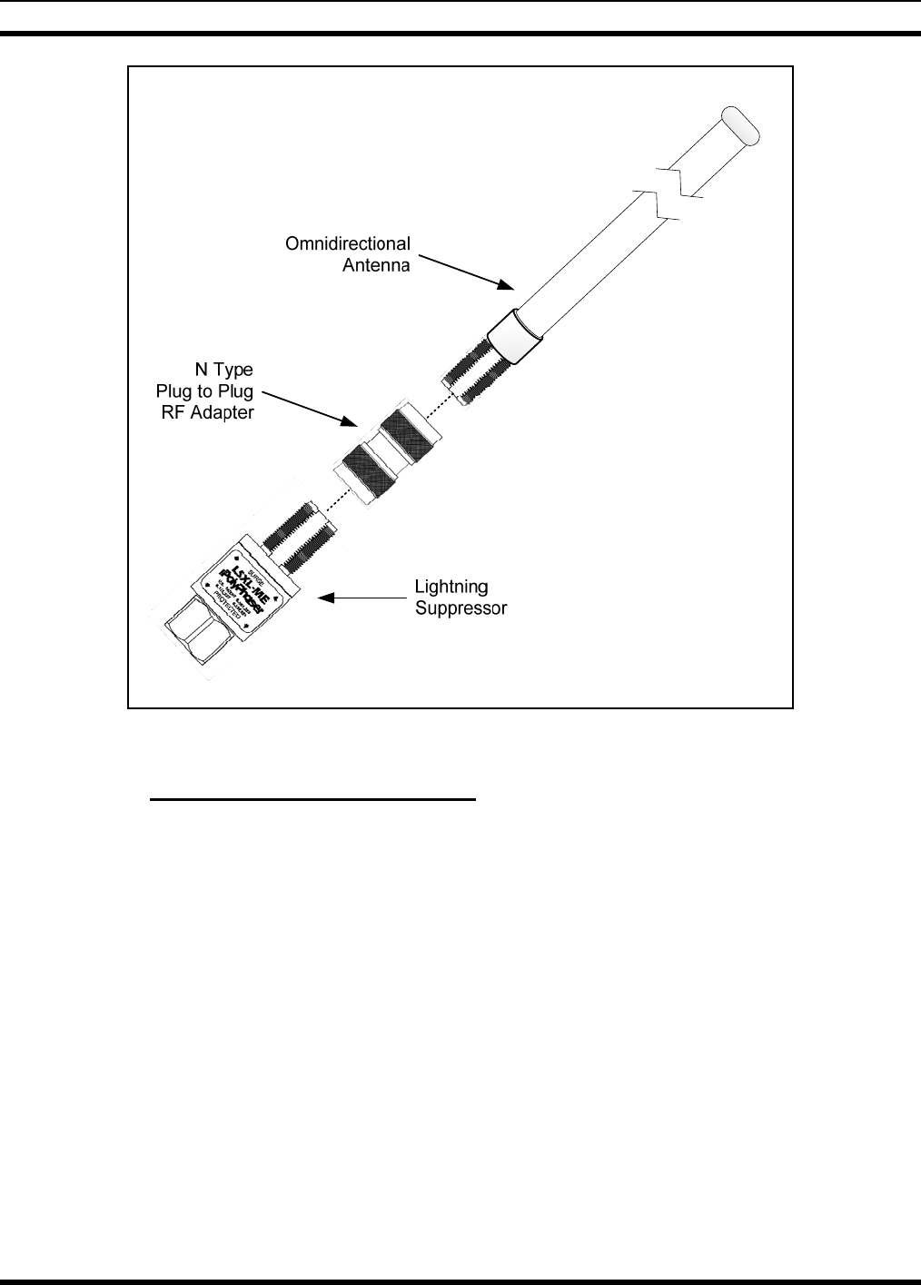
7.8.1 Installing an omni-directional antenna
The omni-directional antenna can be mounted directly to the base station using the following procedure:
1. Connect an N-type male to male RF adapter (not included) to the omni-directional antenna. Hand
tighten the connector.
Recommend using Amphenol 82-100 or RF Industries RFN-1014-1.
2. For the AC version of the base station, if external lightning protection is required, connect the
optional lightning suppressor to the antenna assembly as shown in Figure 7-3.
Recommend using M/A-COM # PT-009560.
3. Connect the completed antenna assembly to the base station antenna connector.
33
MM-009804-001
Figure 7-3: VIDAMAX Base Station Antenna with External Lightning Protection
7.8.2 Installing a Directional Antenna
The directional antenna (weight less than 5 lb and size less than 350x350 mm^2) can be mounted on the
base station using the universal mounting bracket. This mounting bracket is located on the antenna
mounting face (cover) of the base station. The universal mounting bracket can then be adjusted to point
the beam of the antenna in the direction needed for network connectivity. An antenna weighing more than
5 lb cannot be mounted directly on the base station. A separated mounting bracket is required to mount
the antenna directly on the pole while an antenna feeder cable connects the base station to the antenna.
A low loss RF cable (not included) is needed to connect between the base station antenna connector and
the Directional Antenna.
To mount the directional antenna to the base station:
1. Using the four bolts, lock washers and flat washers included in the optional antenna mounting kit,
attach the universal antenna mounting bracket to the base station as shown in Figure 7-4.
2. Attach the antenna panel bracket assembly to the antenna panel.
3. Attach the two bracket assemblies together with the universal knuckle.
34
MM-009804-001
4. Attach the short RF cable between the antenna and the base station antenna port.
Recommend using < 5 ft. long LMR-400 Low loss coaxial cable with field installable N Type Male
connectors, M/A-COM # MAMROS0095.
Figure 7-4: Mounting a Directional Antenna to the VIDAMAX Base Station
7.9 GPS Antenna
The Base Station performs time synchronization through GPS. An external GPS antenna connection is
required. Various antennas are available in the marketplace. One offered by M/A-COM can be mounted
directly onto the base station, or alternatively attached to the pole.
7.9.1 Installing Optional GPS Antenna
To connect GPS cable to base station:
Connect the SMA-type plug of the GPS antenna cable to the SMA receptacle on the base station. Route
the cable to the GPS antenna location. This will be a temporary connection until the installation is
complete.
To install the GPS Antenna:
The GPS antenna kit (M/A-COM # MAMROS0023) includes the GPS antenna (part number ANPC-
185B-Y-180-SM) and various mounts.
Based on how the base station is physically positioned, the mounting location that is uppermost is where
the antenna can be mounted in order to have best access to the satellites in the sky. Connection to the
antenna port is made through the SMA female connector on the base station. Optionally, for lightning
protection, a protection device can be externally installed.
After installing the antenna, dress and secure the cable.
35
MM-009804-001
7.10 RADIO CHASSIS AND CABLING
7.10.1 Attaching Base Station Cables
To connect power to Base Station
1. Connect the M/A-COM power cable to the proper power source.
2. Mate the other end of the power cable’s connector to the 3-pin power connector on the base station by
visually aligning the key and firmly push and turn the outer locking ring clockwise until it stops. A
click will be sensed to confirm proper mating.
3. For added protection against long-term exposure to weather, industry techniques for sealing the data
connection may optionally be performed.
To connect data cable to Base Station
1. Fabricate the Ethernet (AC base station) or Fiber Optic cable (DC base station) as described in
Section 11 or the manufacturer’s instructions.
2. Connect one end of the cable to the LAN connection.
3. Mate the other end of the power cable’s connector to the 3-pin power connector on the base station by
visually aligning the key and firmly push and turn the outer locking ring clockwise until it stops. A
click will be sensed to confirm proper mating.
4. Ensure the dust cap is fully seated on the service port.
5. For added protection against long-term exposure to weather, industry techniques for sealing the data
connection may optionally be performed.
CAUTION
Upon connection, verify that all cabling is not under any stress, a service loop is
maintained, and the cabling is restrained according industry techniques.
36
MM-009804-001
8 OPERATION
To operate the VIDAMAX Base Station, a Linux-based computer using Category 5 Ethernet cable is
required and described in the following sections.
8.1 LOGGING INTO THE VIDAMAX BASE STATION
To login to the VIDAMAX Base Station:
1. Connect the base station to a Linux-based computer using a Category 5 cable.
2. Power up the base station. Once powered up, the base station takes about 2-3 minutes to boot.
3. After 2-3 minutes, begin a Telnet session to communicate with the base station by entering the
following command at the prompt:
pico@pico:~$ telnet IP address of base station Enter
4. This will make the following prompt appear:
login@IP address of base station:
5. At the above prompt, enter the command shown below:
login@IP address of base station: root Enter
6. With the above command, the user is logged into the base station as the root, which is seen by the
prompt shown below:
root@IP address of base station:
7. Enter the next step to load the necessary drivers into the digital board and run Picotools:
root@IP address of base station: cd /ixa Enter
ixa@IP address of base station: ./pc102start Enter
8.2 TESTING THE VIDAMAX BASE STATION
To run the Test Program
1. Open a new terminal window and change the director to the working directory:
pico@pico:~$ cd TXRX_Test Enter
2. Once in the working directory, start the test program named TXRX_Test:
FCC_Test@pico:~$ ./TXRX_Test Enter
37

MM-009804-001
3. The program causes a menu-driven screen to appear as illustrated below:
0 : Exit
1 : Change Channel :
2 : Transmit ON / OFF :
Enter Your Choice :
4. To change the channel, type “1” and at the succeeding prompt enter the desired channel number:
0 : Exit
1 : Change Channel :
2 : Transmit ON / OFF :
Enter Your Choice : 1 Enter
Enter Channel Number : 10 Enter
5. To make the radio transmit, type “2” and at the succeeding prompt enter “1”:
0 : Exit
1 : Change Channel :
2 : Transmit ON / OFF :
Enter Your Choice : 2 Enter
Turn Transmit ON/OFF : 1 Enter
6. When transmit is turned on, an OFDM signal is transmitted continuously.
To run the “TXRX_Test” program on a different base station
1. Power up the new base station and login as root using the new base station’s IP address.
2. Modify the “Setup.txt” file with the IP address of the new base station.
38

MM-009804-001
9 TROUBLESHOOTING AND SERVICING
9.1 TUNING AND CALIBRATION PROCEDURE
Every VIDAMAX Base Station is fully calibrated for frequency and power before shipment to ensure
compliance with FCC requirements. No further tuning is required by the customer or installer during the
installation process.
9.1.1 Transmit Frequency Accuracy Calibration
The accurate frequency setting is a key parameter for VIDAMAX Base Station. Base station frequency
accuracy is guaranteed by a Voltage Controlled Temperature Compensated Crystal Oscillator (VCTCXO)
with 1.5 ppm frequency drift over full temperature range. The factory calibration procedures calibrate the
default VCTCXO setting to minimize the frequency error. This minimizes the frequency variation from
base station to base station. The base station will automatically use default value after each reboot.
9.1.2 Transmit Power Level Calibration
The power level calibration is performed at CH1, CH5, CH10 (lowest, middle, and highest) to ensure the
over-band performance. An Agilent PSA E4440A under spectrum emission mask mode is used to
perform the calibration. A standard baseband OFDM QPSK 3/4 Signal (Downlink Burst, 50% duty, 10
msec. frame) is used for the calibration. The on board 30 dB/ 1 dB step attenuator is used to adjust power
level. The cable loss (radio antenna port to PSA input) is calibrated out so the PSA can measure channel
power at the antenna port. After the TX power level calibration step, the FCC emission mask is used to
check TX spectrum at CH1, CH5 and CH10 to ensure the compliance. After calibration, the base station
uses the calibrated TX power as a default value to initialize the radio.
39
MM-009804-001
10 RADIO CHASSIS
40
MM-009804-001
11 CABLE FABRICATION
11.1 ETHERNET CABLE PLUG KIT
For the AC version of the base station, the Ethernet cable connected to the base station uses a RJ-45
connector protected by an Industrial Circular Ethernet plug assembly that protects the RJ-45 connector
from the elements.
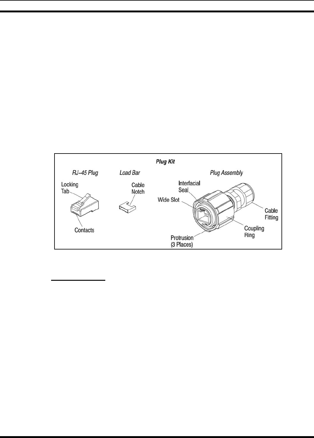
The Stranded Wire Plug Kit (Tyco Electronics # 1738607-2), shown in Figure 11-1, consists of an
8-position Category 5e RJ-45 plug, load bar, and plug assembly. The load bar is used to hold the cable
wires for insertion into the RJ-45 plug. The RJ-45 plug must be terminated and then installed into the
plug assembly. The RJ-45 plug is held in the plug assembly by the locking tab. The cable fitting holds
the RJ-45 plug in the plug assembly and seals the plug at the cable end. When engaged, the connectors
are held together by a locking mechanism (coupling ring and bayonet lock), which prevents accidental
disconnection. The engaged connectors are sealed by the interfacial seal.
Figure 11-1: Tyco/Electronics Industrial Circular Ethernet Connector Plug Kit (1738607-2)
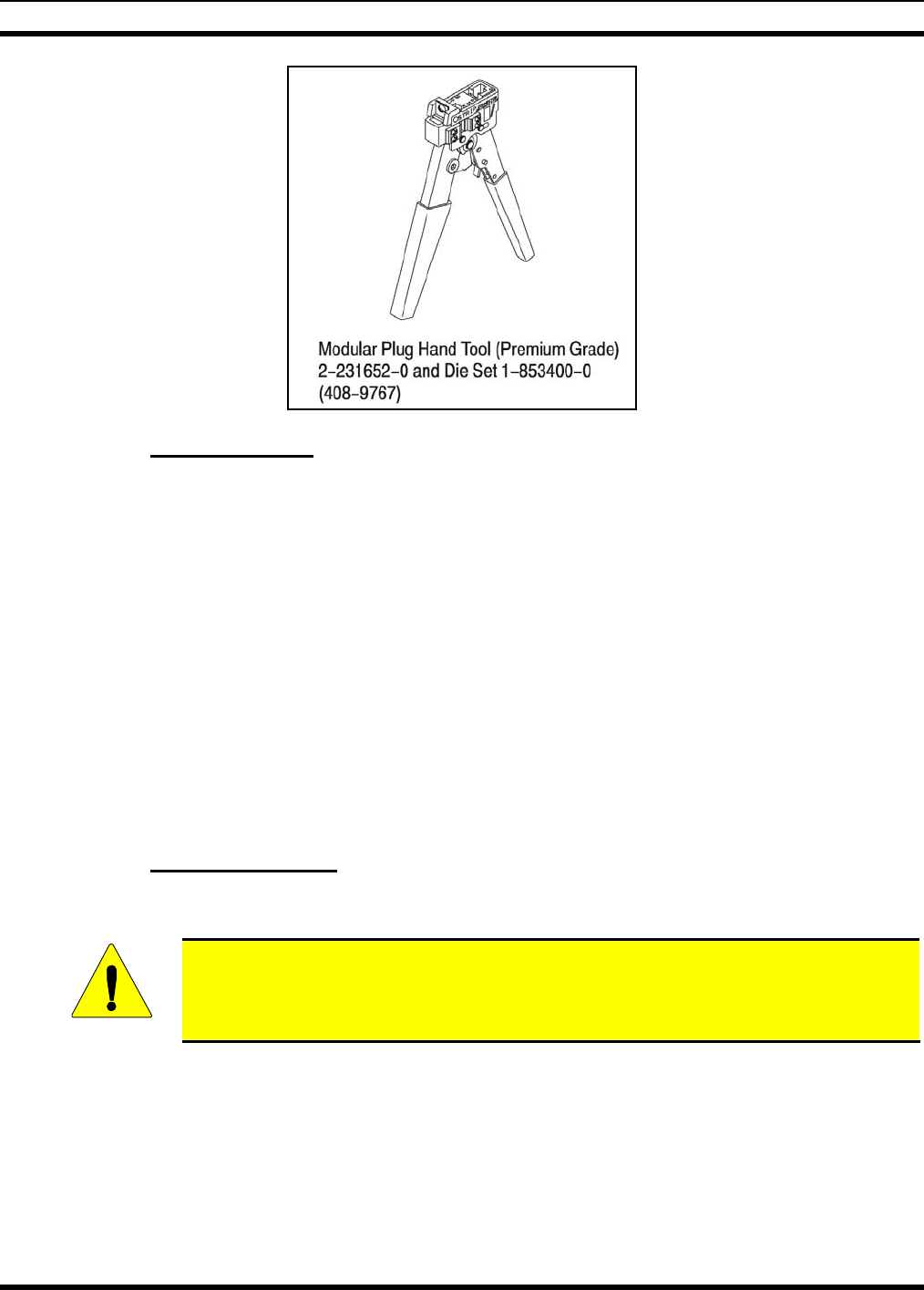
11.1.1 Tools Required
• Modular Plug Hand Tool, 3-231652-0 (Tyco/Electronics-AMP)
Includes; Hand Tool, 2-231652-0 and Die Set, 1-853400-0
41
MM-009804-001
11.1.2 Cable Selection
The RJ-45 plug will accept Category 5e, 100–ohm unshielded round cable with the following
specifications:
• Cable type: 8–conductor
• Conductor size: 24 AWG
• Conductor type: 7–strand copper
• Conductor insulation diameter: 0.039 in. (0.99 cm) maximum
• Cable jacket diameter range:
RJ-45 plug accepts: 0.190 through 0.220 in. (4.83 through 5.59 cm) OD (single jacket)
Cable fitting accepts: 0.18 through 0.31 in. (4.6 through 7.9 cm) OD (double jacket)
11.1.3 Cable Preparation
Prepare the cable using the following procedure:
CAUTION
Reasonable care must be taken not to scrape or nick any part of the cable during
the stripping operation.
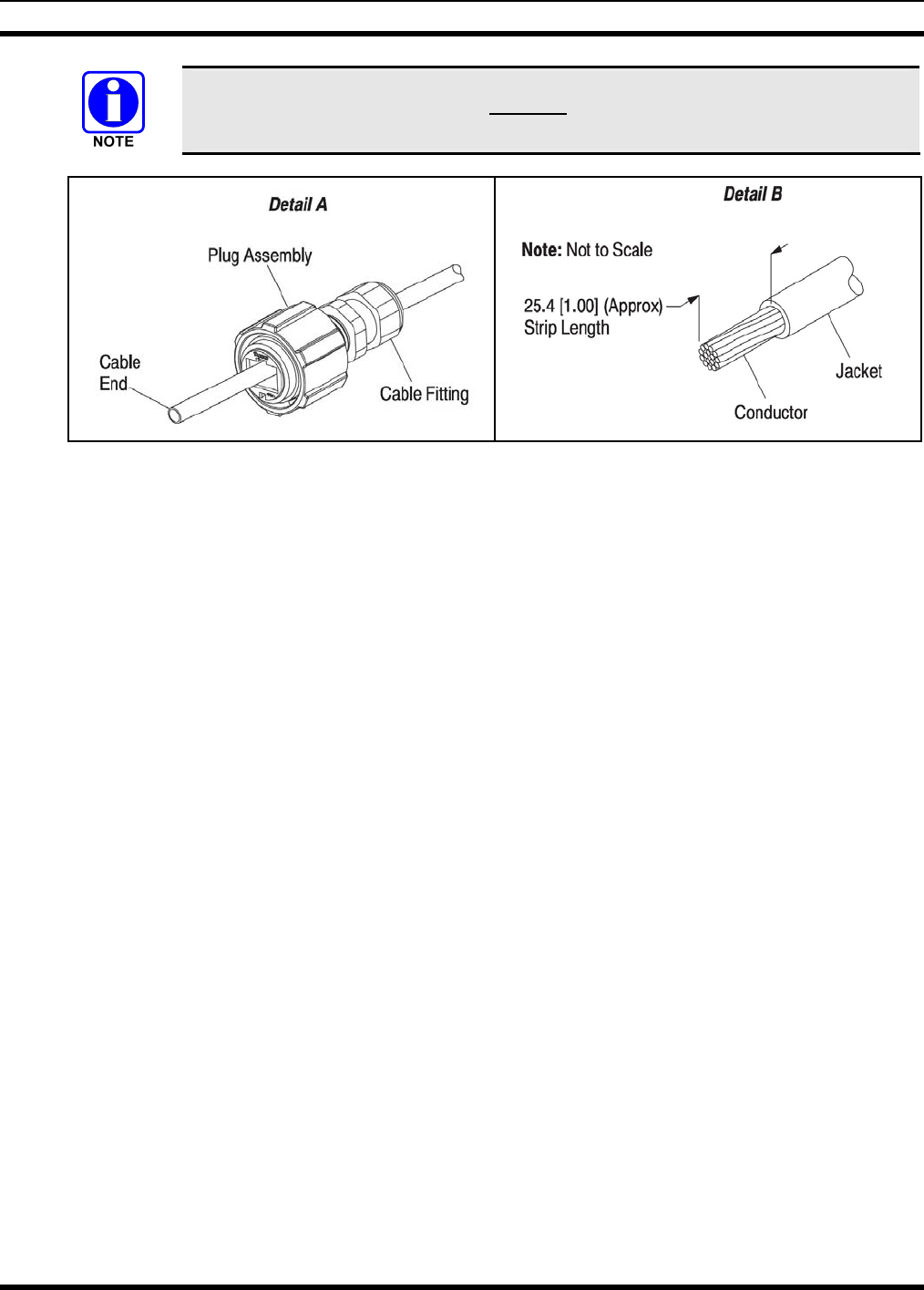
1. Slide the plug assembly (cable fitting end first) onto the cable. See Figure 11-2, Detail A.
2. Proper strip length is necessary to insert the conductors into the contact slots. The recommended strip
length is given in Figure 11-2, Detail B.
42
MM-009804-001
Insulation of individual conductors must not be cut or removed. This could result in
shorted or open connections.
Figure 11-2: Cable Preparation
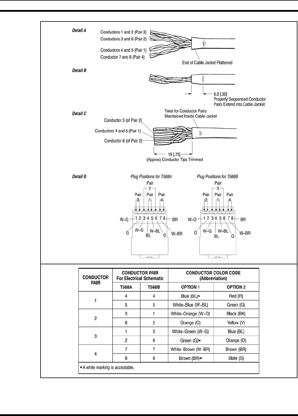
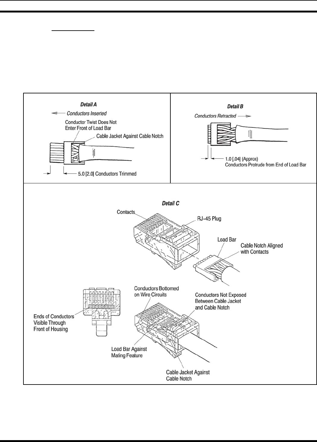
3. Conductor pairs must be oriented side–by–side in the order shown in Figure 11-3, Detail A. The end
of the cable jacket must be flattened so that the conductor pairs lay side–by–side.
4. Properly sequenced conductor pairs should extend into the cable jacket to the dimension given in
Figure 11-3, Detail B, creating an oblong shape.
5. The conductor tips must be trimmed evenly to the dimension shown in Figure 11-3, Detail C. Proper
orientation of conductors must be maintained.
6. The conductor pairs must be untwisted and arranged according to EIA/TIA T568A or T568B (defined
in Figure 11-3, Detail D). IT IS CRITICAL that the pairs are NOT untwisted inside the cable jacket.
When arranging conductor pairs, IT IS IMPORTANT that Conductor 6 be crossed over Conductors 4
and 5 as shown in Figure 11-3, Detail C.
43
MM-009804-001
Figure 11-3: Cable Preparation Continued
44
MM-009804-001
11.1.4 Termination
Terminate the RJ-45 plug to the cable end using the following procedure:
1. The conductors (maintaining arrangement) must be inserted into the load bar (oriented so that the
cable notch will align with the contacts) until the cable jacket rests against the cable notch. The
conductor twist must not enter the front of the load bar. The conductors must be trimmed evenly and
square with the front edge of the load bar to the dimension given in Figure 11-4, Detail A.
Figure 11-4: Termination Requirements
45
MM-009804-001
2. The conductors must be retracted from the load bar so that the conductors protrude from the end of
the load bar to the dimension given in Figure 11-4, Detail B. The top of the load bar must not be
deformed.
If the load bar is deformed, the conductor twist entered the front of the load bar
3. The load bar (oriented so that the cable notch is aligned with the contacts) must be inserted into the
RJ-45 plug until it butts against the mating feature of the RJ-45 plug, and the conductors are bottomed
on the wire circuits. The cable jacket must be against the cable notch after the load bar is fully seated.
The conductors must not be exposed between the cable jacket and cable notch. The ends of the
conductors must be clearly visible through the front of the RJ-45 plug. See Figure 11-4, Detail C.
If the conductors do not bottom on the wire circuits, they must be re-trimmed (after
removing the load bar/cable assembly from the RJ-45 plug), and re-inserted into the
RJ-45 plug. If the conductors are too short, the cable must be re-stripped.
4. The RJ-45 plug must be terminated to the cable according to the instructions included with the
tooling.
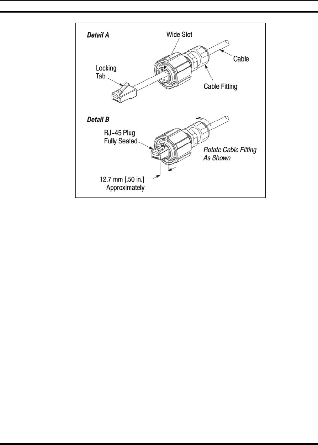
11.1.5 Assembly
Assemble the RJ-45 connector into the plug assembly using the following procedures:
1. Align the locking tab of the RJ-45 plug with the wide slot at the front (end opposite the cable fitting)
of the plug assembly. See Figure 11-5, Detail A.
2. Depress the locking tab, and insert the RJ-45 plug into the plug assembly. Gently pull the cable until
the RJ-45 plug is fully seated. There should be approximately 12.7 mm [.50 in.] of the RJ-45 plug
protruding from the front of the plug assembly. See Figure 11-5, Detail B.
CAUTION
To avoid damage to the connection, the cable must be pulled GENTLY when
seating the RJ-45 plug.
3. While holding the RJ-45 plug in position, rotate the cable fitting as shown in Figure 11-5, Detail B
until tightened to a torque of 1.13 N–m [10 lbf–in.].
The given torque must be met in order for the cable fitting to seal the plug at the cable
end.
46
MM-009804-001
Figure 11-5: Assembly Detail
47

M/A-COM Wireless Systems
221 Jefferson Ridge Parkway
Lynchburg, Virginia 24501
(Outside USA, 434-385-2400) Toll Free 800-528-7711
www.macom-wireless.com Printed in U.S.A.