HARXON HX-DU1006D Wireless Data Transceiver Module User Manual HX DU1006D V1 0
HARXON CORPORATION Wireless Data Transceiver Module HX DU1006D V1 0
HARXON >
User manual
[HX-DU1006D User Manual] Harxon Corporation
1
HX-DU1006D Wireless data transceiver
User Manual
Version: V1.0

[HX-DU1006D User Manual] Harxon Corporation
2
CONTENTS
1 SUMMARY...........................................................................................................................................4
1.1 Frequency Range ................................................................................................................. 4
1.2 Operating Mode .................................................................................................................. 4
1.3 Application .......................................................................................................................... 4
2 INSTALLATION DESIGN...................................................................................................................5
2.1 Installation of Radio ............................................................................................................ 6
2.2 Main Power Supply (3.3 Vdc) ............................................................................................. 6
2.3 Data Interface Connector .................................................................................................... 7
3 RADIO MODEM CONFIGURATION AND DIAGNOSTIC COMMANDS......................................8
3.1 Errors Messages .................................................................................................................. 9
3.2 Initialize Configuration ....................................................................................................... 9
4 TROUBLESHOOTING......................................................................................................................10
5 TECHNICAL SPECIFICATIONS......................................................................................................10
[HX-DU1006D User Manual] Harxon Corporation
3
Copyright Information
This products operation manual and all the related software are protected by
Harxon Corporation, and all rights reserved. All rights of this manual include
copyright only belongs to Harxon Corporation (short for Harxon as below), unless the
copyright holders allowed, strictly forbid to copy this manual by printing、copying、
recording and other means.
Disclaimer
We strive to guarantee the accuracy and completeness of this manual content
when compiling, but for possible errors or omissions, Harxon will not assume any
responsibility. Due to the continuous development of technology, Harxon reserves the
rights to change the technical specifications or functions of their products without any
notification to users.
Antenna Installation Warning
1. Any antenna only can be installed and maintained by professional technician.
Please make sure that the radio station is closed when you maintain or work nearby
the antenna.
2. In general, data transmitter module will be connected to a directional (high-gain)
antenna. Under normal circumstance, only the professional technicians can close to
the antenna area, anyone can’t touch the antenna or close to 0.6m in diameter range of
the antenna.
Antenna Gain vs Safe distance recommended
Antenna Gain
0–5 dBi 5–10 dBi 10–16.5 dBi
The minimum safe distance 0.6m 1.06m 2.3m
The product's antenna gain is 3.5dBi.
[HX-DU1006D User Manual] Harxon Corporation
4
1 Summary
This manual is the installation and operating instructions of HX-DU1006D
wireless data transceiver. HX-DU1006D is a universal wireless data transceiver
module, adopted compact、modular plat-shaped structure, which is very suitable for
designer-users to integrate RTUs、PLCs、banking automation equipments or similar
devices.
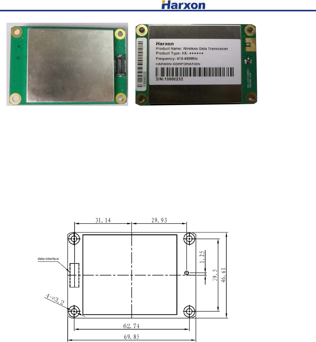
Figure 1 HX-DU1006D Data transceiver
1.1 Frequency Range
HX-DU1006D operating frequency range is 410MHz~470MHz,frequency of
transmitting and receiving can be set by programming.
1.2 Operating Mode
Half-duplex mode is sending data for master transmitter input, receiving data if
no input. When HX-DU1006D operates in half-duplex mode, emission will be started
when data appears.
Note: HX-DU1006D does not support duplex operating (Such as transmitting and
receiving simultaneously).
1.3 Application
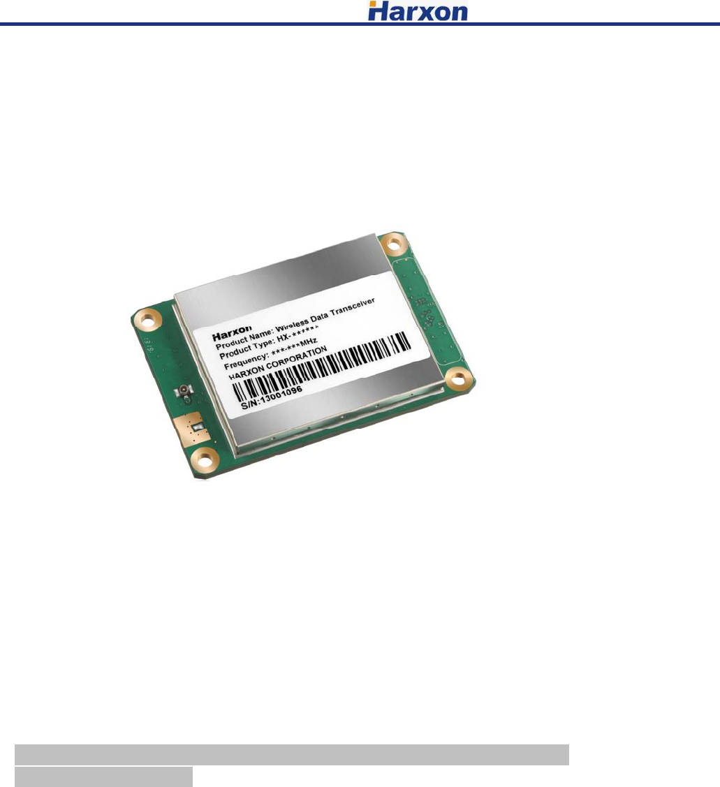
Radio modem apply to point to multi-point and point to point and other
applications, one point to multi-point (MAS) is the most common application of radio,
which consists of a central master station and several related remote units, like figure
2. MAS network supply communication between a central host and remote terminal
units (RTUs) or other data acquisition equipments. As to computer equipments, the
radio operating is transparent, so, radio transmitting data as its original form, there is
no change in the data format.
[HX-DU1006D User Manual] Harxon Corporation
5
Figure 2 MAS one point to multi-point network
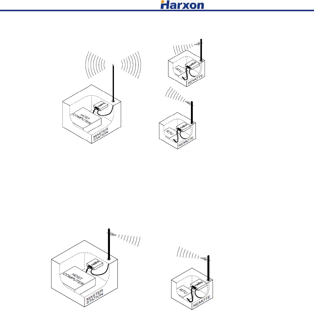
Point to point system
In the case of licensed, HX-DU1006D can be configured as point to point system,
which consists of two radios: one on the host, and the other on remote terminal units,
detailed as figure 3. Data transmitting between two points of this system can set up
simplex or half-duplex communication connection.
Figure typically point to point connection
2 Installation design
This radio has two connection ports: one is the board to board connector which
supplies the data interface and DC power line; another is the 50ohm RF connector. To
get a good connection, the RF connector and board to board connector should be
applied some pressure. Figure 4 shows the external connection interface of radio
modem.
[HX-DU1006D User Manual] Harxon Corporation
6
Figure 4 external connection interface
All circuits of radio modem are masked in a shielded box, to reduce interference
to nearby products. Transmitter can be set as transmitting 1W RF output power, so in
order to reducing the RF interference to nearby electronic equipments, carefully
choosing and designing the RF transmission path is very important.
2.1 Installation of Radio
Figure 5 shown the installation dimension of data transceiver module, firmly
fitted the radio modem onto the mounting surface of user system by holes on radio
modem 4 corners (no fasteners supplied).
Figure 5 Radio Modem installation dimension
2.2 Main Power Supply (3.3 Vdc)
DC Power Supply
HX-DU1006D can operate with any 3.3V power supply, which comes from data
interface connector with good filtered. The power must supply 1.5A current at least
and featured with current-limiting, even if you make radio modem operating on low
power mode (0.5W).
[HX-DU1006D User Manual] Harxon Corporation
7
Note: HX-DU1006D only applies to negative grounding system; there is no fuse
or reverse polarity protection on PCBA.
Power supply positive must be provided by 23、 24、25、26、27、28 pin, data
and power grounding should be connected to 1、5、7、9、19、20、21、22 and 30 pin.
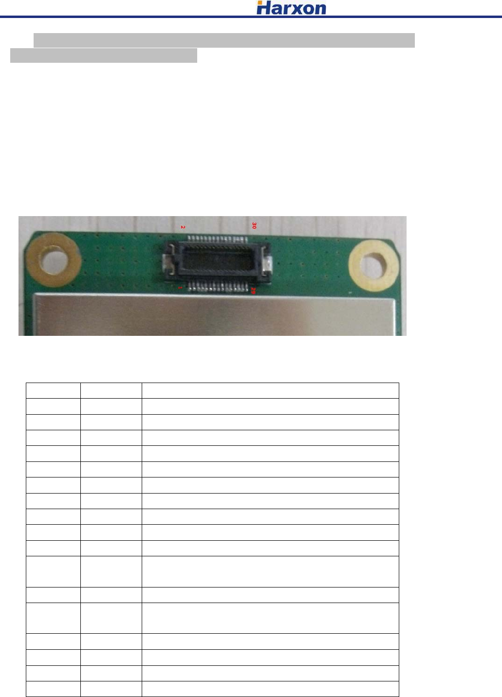
2.3 Data Interface Connector
Normally, data interface level is TTL; refer to figure 6 and Table 4, which is the
detailed description of interface connector. Some pins of data interface connector use for
factory testing, only connect the possible pins for using, improper connection may cause
damage to the radio.
Figure 6 Data Interface Connector
Table 3 Definition of data interface connector pin
Pin No. Function Description
1 GND Ground for signal and power
2 NC No connection
3 RXD Received data from external device
4 NC No connection
5 GND Ground for signal and power
6 RX Clock RX Clock for SPI
7 GND Ground for signal and power
8 TX Clock TX Clock for SPI
9 GND Ground for signal and power
10 NC No connection
11 Config_EN L:Command configuration mode;
H:Data transmission mode
12 RSSI Received signal strength indicator(0.5-2.5V)
13 T/RX SW TX/RX mode switch
TX mode output H level, RX mode output L level
14 TXD Sent data to external device
15 NC No connection
16 NC No connection
17 NC No connection
[HX-DU1006D User Manual] Harxon Corporation
8
18 VCC Regulated 3.3V DC
19 GND Ground for signal and power
20 GND Ground for signal and power
21 GND Ground for signal and power
22 GND Ground for signal and power
23 VCC Regulated 3.3V DC
24 VCC Regulated 3.3V DC
25 VCC Regulated 3.3V DC
26 VCC Regulated 3.3V DC
27 VCC Regulated 3.3V DC
28 VCC Regulated 3.3V DC
29 NC No connection
30 GND Ground for signal and power
3 Radio Modem Configuration and diagnostic commands
Radio modem configuration and diagnostics achieved by data interface
connector, commands are controlled by PC or a dedicated terminal equipment. For
final user, an EIA/RS-232 to TTL conversion circuit is needed to control the radio
modem. Radio modem must be removed from user’s equipments or installed modules
when configuration or diagnostics.
Special tools can be used for setting the radio modem before final installation.
Note: In order to entry configuration mode, the Config_EN pin (11 pin of data
connector) should be set to “L” or GND. And in normal mode, this pin should be
pulled up or floated.
Table 4 listed every command entities and a simple functional description.
Programming information is displayed in square brackets, command names followed.
If you want to input a command, type the command first, and then press the button of
“ENTER”
As to programming command, pressing space button after commanding, and then
pressing the corresponding information or parameter values, press “ENTER” button
finally.
Table 4 Command Set
Command Function
Transmitting Frequency
Setting Command
TX[XXX]
Set TX Frequency: TX+Space+Frequency Value+Enter
Query TX Frequency: TX+Enter
Receiving Frequency Setting
Command RX[XXX]
Set RX Frequency: RX+Space+Frequency Value+Enter
Query RX Frequency: RX+Enter
Baud Rate Setting Command
BAUD[XXX]
Set Baud Rate: BAUD+Space+Baud Rate Value+Enter
Query Baud Rate: BAUD+Enter
Power Setting Command
PWR[XXX]
Set the Power Level: PWR+Space+Power Level+Enter
Query the Power Level: PWR+Enter
Note: Power level has two kinds: H and L.
[HX-DU1006D User Manual] Harxon Corporation
9
Protocol Setting Command
PRT[XXX]
Set the Protocol Type: PRT+Space+Protocol Name+Enter
Query the Protocol Type: PRT+Enter
Software Version Query
Command
SREV [XXX]
Software Versions Query: SREV+Enter
Serial Number Query
SER[XXX] Serial Number Query: SER+Enter
Frequency Lower Limit
Query Command
FLOW[XXX]
Frequency Range Lower Limit Query: FLOW+Enter
Frequency Upper Limit
Query Command
FUPP[XXX]
Frequency Range Upper Limit Query: FUPP+Enter
3.1 Errors Messages
Errors Messages may occur in the processing of terminal interface listed as
below:
UNKNOWN COMMAND—unrecognized command. Please refer to the command
description in the command using information.
INCORRECT ENTRY—command format or parameter values are incorrect. Please
refer to the command description in the command using information.
ACCESS DENIED—command can’t be completed successfully, this command may
be allowed by final user.
3.2 Initialize Configuration
Some basic setting steps of radio configuring into user’s products as below, in
most cases, these steps are sufficient to complete the installation. These steps assume
that radio modem is already installed into user’s system or product, also connected the
data interface and antenna interface well.
1、The radio modem is installed into user’s system or product, and connect data interface and
antenna interface well;
2、Connected to a terminal radio modem via interface of user’s product (serial setting:
asynchronous@ 38400 W/8N1);
3、Enable radio modem configuration mode (pin 11 of radio modem data interface grounding);
4、Checking the configuration parameter of radio modem via serial terminal command (refer to
command set);
5、Checking and setting RF transmitting and receiving frequencies;
6、Checking and confirming the communication protocol type.
Note:
Operating frequency always is not be set when in factory, users need to set the possible
transmitting and receiving frequency via serial command, but the radio modem must be
programmed according to the operating frequency licensed by users.
[HX-DU1006D User Manual] Harxon Corporation
10
8、Disconnect pin 11 of data interface to ground;
9、Connect the data interfaces of data equipment and radio modem for testing.
4 Troubleshooting
Doing some simple checks in advance is a good habit, under normal operating
conditions; the radio modems must meet the basic requirements as below:
• Appropriate and stable power supply;
• Reliable connections (RF, data, power supply);
• Reasonably arranging the antenna system to achieve a good strength of receiving signal;
• The correct operating parameters of programmed radio modem (frequency、serial port baud rate、
air baud rate、power level、protocol type, etc.);
• Interfaces of radio modem and data equipments connected correctly.
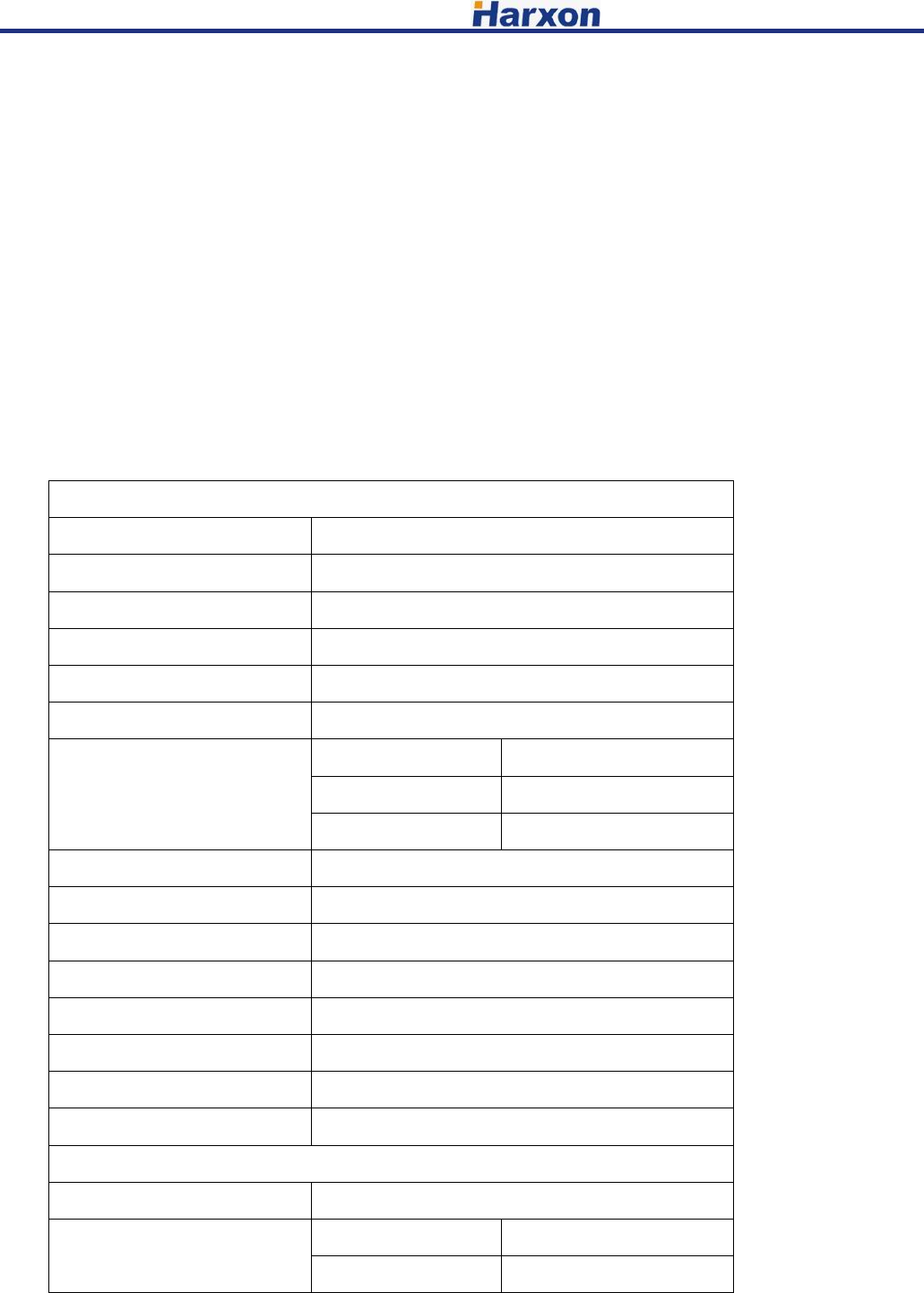
5 Technical Specifications
General specification
Item Specification
Frequency range 410~470MHz
Operating Mode Half-duplex
Channel spacing 12.5KHz
Modulation type GMSK、4FSK
Operation voltage 3.3V
Power dissipation(Typical)
High power level 3.3W @3.3V
Low power level 2.7W @3.3V
Receiver 0.5W @3.3V
Frequency stability ≤±1.0ppm
Size 70×47×11mm
Weight 88g
Temperature(operation) -40~+70℃
Temperature(storage) -40~+85℃
Antenna port IPEX or MMCX
Antenna impedance 50ohm
Data interface 30pin 0.5mm
Transmitter
Item Specification
RF output power High level 30±1dBm@DC 3.3V
Low level 27±1dBm@DC 3.3V
[HX-DU1006D User Manual] Harxon Corporation
11
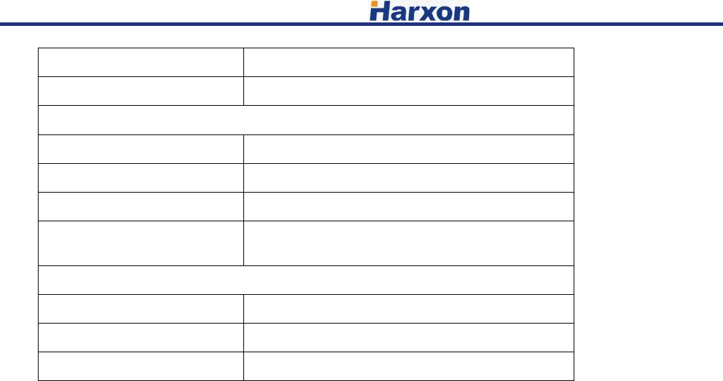
Power stability ±1dB
Harmonics <-30dBm
Receiver
Item Specification
Sensitivity -115dBm@BER 10-3,9600bps
Co-channel rejection >-12dB
Adjacent channel
selectivity >52dB@25KHz
Modem
Item Specification
Data Link rate 19200bps 9600bps
Modulation type GMSK、4FSK
Only service personnel have access to the programming capabilities.
The end users in all these cases must not be able to program the radios
4800pbs
FCC Radiation Exposure Statement
This equipment complies with FCC radiation exposure limits set forth for an controlled environment.
This equipment should be installed and operated with minimum distance 60cm between the radiator & your body
This Licensed transmitter is approved as a module for installation into the final devices
providing this FCC criteria is met:
1. The final device is designed for mobile or fixed operation.
2. The maximum antenna gain to allow compliance with RF exposure
requirement that is listed on the Grant of Certification must be followed.
3. If the label of the module is not visibleon the final device, the final device
should contain the following text: "Contains FCC ID:2ACRAHX-DU1006D