HARXON HX-DU8602T Wireless Data Transceiver User Manual HX DU8602T V1 2
HARXON CORPORATION Wireless Data Transceiver HX DU8602T V1 2
HARXON >
user manual

[HX-DU8602T User Manual] Harxon Corporation
1 /10
HX-DU8602T
User Manual
Version:V1.2
WIRELESS DATA TRANSCEIVER

[HX-DU8602T User Manual] Harxon Corporation
2 /10
CONTENTS
1、SUMMARY...................................................................................................................................................................4
2、INTERFACE...................................................................................................................................................................4
2.1 SERIAL DATA LINE INTERFACE..............................................................................................................................................4
2.2 RF INTERFACE.....................................................................................................................................................................4
3、FUNCTIONANDOPERATINGINSTRUCTION...................................................................................................................5
3.1 BOOTING.............................................................................................................................................................................5
3.2 HIGH/LOW RF POWER SWITCHING.......................................................................................................................................5
3.3 TRANSMITTING CHANNEL SWITCHING.................................................................................................................................5
3.4 CHANNEL DISPLAY..............................................................................................................................................................5
3.5 LOW VOLTAGE INDICATOR....................................................................................................................................................5
3.6 OVERVOLTAGE INDICATOR..................................................................................................................................................6
3.7 DATA TRANSMITTING INDICATOR........................................................................................................................................6
4、RADIOSETTING............................................................................................................................................................6
4.1 OPEN PORTS.........................................................................................................................................................................6
4.2 ENTRY THE CONFIGURATION MODE......................................................................................................................................7
4.3 CONFIGURING THE PARAMETER RADIO MODEM...................................................................................................................7
4.4 FINISH TO EXIT THE CONFIGURATION MODE.........................................................................................................................8
5、SOFTWAREUPGRADING.............................................................................................................................................9
6、TECHNICALSPECIFICATIONS.......................................................................................................................................10

[HX-DU8602T User Manual] Harxon Corporation
3 /10
Copyright Information
This products operation manual and all the related software are protected by Harxon Corporation,
and all rights reserved. All rights of this manual include copyright only belongs to Harxon Corporation
(short for Harxon as below), unless the copyright holders allowed, strictly forbid to copy this manual by
printing、xeroxing、recording and other means.
Disclaimer
We strive to guarantee the accuracy and completeness of this manual content when compiling, but
for possible errors or omissions, Harxon will not assume any responsibility. Due to the continuous
development of technology, Harxon reserves the rights to change the technical specifications or functions
of their products without any notification to users.
Antenna Installation Warning
1. Any antenna only can be installed and maintained by professional technician. Please make sure that the
radio station is closed when you maintain or work nearby the antenna.
2. In general, radio will be connected to a directional (high-gain) antenna, and fixed to the edge or top of
building or top of tower. According to the application and antenna gain, total hybrid power may exceed
90W (ERP). Under normal circumstance, only the professional technicians can close to the antenna area,
anyone can’t touch the antenna or close to 2.3m in diameter range of the antenna.
Antenna Gain vs Safe distance recommended
Antenna Gain: Maximum 3.5dBi
Safe distance: 2.30m
[HX-DU8602T User Manual] Harxon Corporation
4 /10
1、Summary
HX-DU8602T is an external transmit-only high-power UHF radio modem, waterproof of IP67、
Durable structure,
HX-DU8602T has 4 pieces of LED、1 piece of nixie tube and 3 pieces of push-button, for user’s
convenience of booting、channel switching、power rating、low voltage alarming and indicating the current
operation channel.
2、Interface
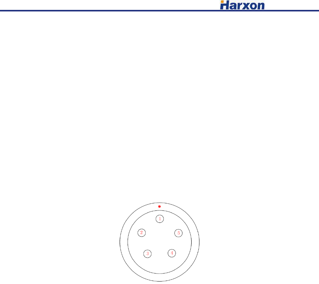
2.1 Serial data line interface
Interface type: asynchronous serial communication standard of RS232
Pin definitions:
Pin 1------Power,9-16V DC; current:<7A
Pin 2------power grounding,Power GND;
Pin 3------serial data receiver,RXD;
Pin 4------serial signal grounding;
Pin 5------serial data transmission,TXD.
2.2 RF interface
HX-DU8602T RF interface is TNC female connector of 50Ω.

[HX-DU8602T User Manual] Harxon Corporation
5 /10
3、Function and operating instruction
3.1 Booting
Press the button of ON/OFF to boot. LED indicator of ON is green, which means the voltage is
normal, and the machine can work normally; if LED indicator of ON is red flash, which means the
voltage is too low, low voltage protection has been worked; if LED indicator of ON is red, which means
the voltage is too high, overvoltage protection has been worked.
3.2 High/Low RF power switching
Pressing the button of PWR for switching RF power level between high and low. If you choose high
power, LED indicator of PWR will turn red; if you choose low power, LED indicator of PWR will turn
green.
3.3 Transmitting channel switching
Pressing the button of CHANL, 8 channels of “1-8” will be switched within each other, keep
pressing for fast forward, digital tube display the current channel number.
3.4 Channel Display
Operation Mode: Display the channel number of “1-8”.
Software upgraded to boot mode: display “b”.
3.5 Low voltage indicator
When the voltage lower than 10V, radio modem will turn on protection, LED indicator of ON will
be red flash; voltage back up to 10.2V, LED indicator show green, radio modem will return to normal
work.
[HX-DU8602T User Manual] Harxon Corporation
6 /10
3.6 Overvoltage indicator
When voltage higher than 16V, the radio modem will turn on protection, LED indicator of ON turn
red; voltage back down to 15.8V, LED indicator will show green, radio modem will return to work
normal.
3.7 Data transmitting indicator
When data transmitting, LED indicator of TX will turn red flash.
4、Radio setting
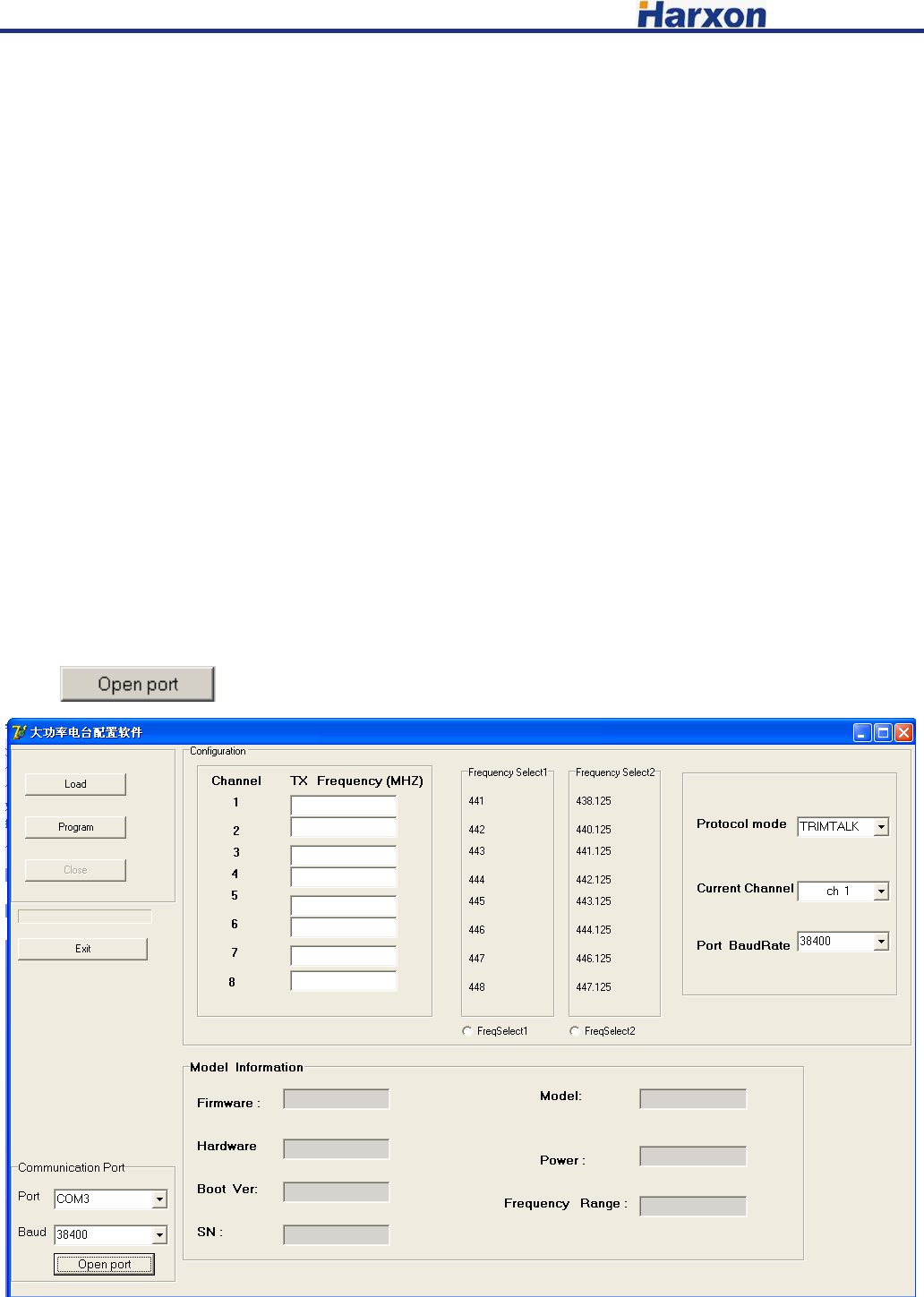
4.1 Open ports
Open the configured software, choose the corresponding port, baud rate defaulted as 38400, click the
button to open serial port.
[HX-DU8602T User Manual] Harxon Corporation
7 /10
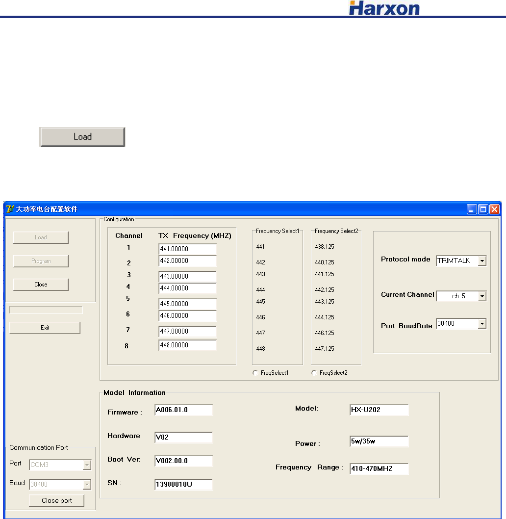
4.2 Entry the configuration mode
Connecting the power line and serial port line, which confirmed to be connected correctly, repower,
press the button of “ON/OFF” for booting, LED indicator of ON show green. Within 3 seconds, click the
button to make the radio modem enter configuration mode, reading and saving the
information of configured radio modem (shown as the chart below), button of “load” failure and turn
gray. Digital tube of radio modem show “C”, radio modem has entered the configuration mode.
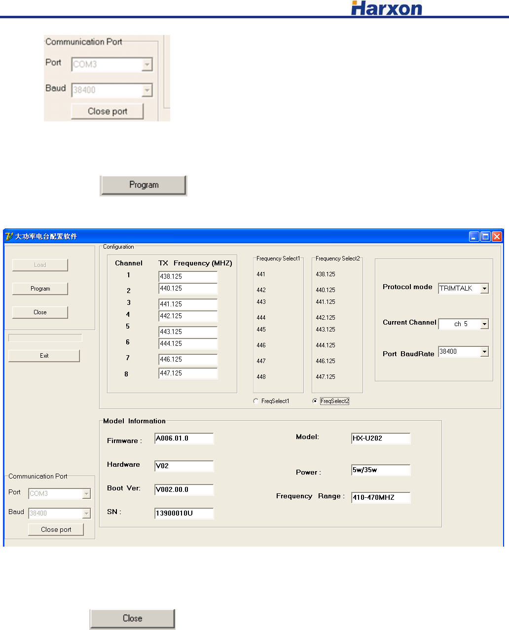
4.3 Configuring the parameter radio modem
4.3.1 Configuring the customed frequency, default frequency setting are as follows:
There are two groups of default frequency value, click “FreSelect1 ” or ”FreSelect2” below to
choose the corresponding set of frequency value.
4.3.2 Configuring the serial baud rate optional 9600,19200,38400,57600,115200 bps. (Note: if you want
to reconnect radio modem after modifying the baud rate of serial port, you have to modify the serial baud
[HX-DU8602T User Manual] Harxon Corporation
8 /10
rate here .
4.3.3 Configuring the current channel ch1-ch8.
Click the button to configure the modem parameter.
4.4 Finish to exit the configuration mode
Click the button to exit configuration mode, the digital tube of radio modem will
show the current channel number.
[HX-DU8602T User Manual] Harxon Corporation
9 /10
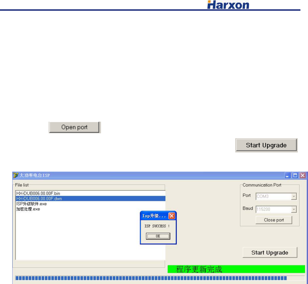
5、 Software upgrading
1)connecting the power data line, serial line of DB9 connected to computer. Pressing two buttons of
“Channel” and “PWR” simultaneously before power on, and then pressing the button of “ON/OFF” to
turn on the machine, LED indicator of “ON” show green. Checking and confirming digital tube show “b”,
entering the upgrading mode.
2)Open the firmware upgrading software, choose the corresponding port, choose baud rate 115200,
click the button to open the port.
3)Choose the upgrading file “******.dwn” in the same path, click the button
to upgrade the firmware. Please don’t break off operation in the process of upgrading!
4) After finishing the upgrading, upper computer software will pop-up a dialog box to remind you
of upgrading successfully, radio modem resetting, digital tube show bright, which means you upgrade
successfully.
[HX-DU8602T User Manual] Harxon Corporation
10 /10
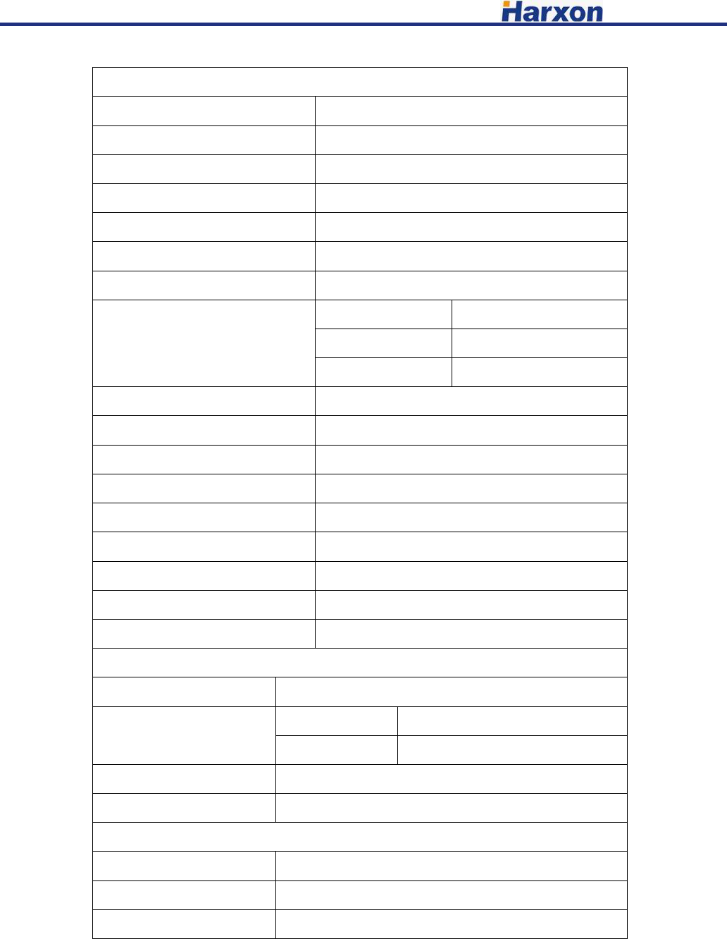
6、Technical Specifications
General Specifications
Item Specifications
Frequency Range 410~470MHz
Numbers of Channel 8
Operating Mode Simplex
Channel Spacing 12.5KHz
Modulation GMSK、4FSK
Operating Voltage 9~16V DC
Power Consumption
(typical)
High power level 70W@DC 12V
Low power level 35W@DC 12V
Standby 1.5W@DC 12V
Frequency Stability <±1ppm
Water proof level IP67
Dimension 186×140×73mm
Weight 1.5kg
Operating Temperature -30~+60℃
Storage Temperature -40~+70℃
Antenna Interface TNC,female
Antenna Interface Impedance 50ohm
Data Power Interface HGG.1B.305
Transmitter Specifications
Item Specifications
RF output power High power 45.5±0.5dBm@DC 12V
Low power 37±0.5dBm@DC 12V
RF Power Stability ±1dB
Harmonics <-30dBm
Modem
Name Requirements
Data link Rate 9600bps、19200bps
Modulation GMSK、4FSK
Operation Voltage: DC 9.0V~16V
Only service personnel have access to the programming capabilities.
The end users in all these cases must not be able to program the radios
4800pbs
This equipment complies with FCC radiation exposure limits set forth for an controlled environment.
This equipment should be installed and operated with minimum distance 2.30m between the radiator & your body
FCC Radiation Exposure Statement