HARXON HX-DU8616D Wireless data transceiver User Manual final eRadio 20180930
HARXON CORPORATION Wireless data transceiver final eRadio 20180930
HARXON >
Users Manual

Version/Warranty/Repair/Copyright
Version Information
Version Number: V1.0
Version Date: August 30, 2018
Warranty Period
eRadio: 1 year
Instruction of Returning to the Factory
If something is wrong with the product, it should be returned to the factory,
please contact us.
Copyright Information
The operation guide of this product and all involving software are protected by
Shenzhen Harxon Antenna Technology Co., Ltd (hereinafter referred to as
Harxon). All rights reserved. All rights of this manual, including copyright, are
exclusively owned by Harxon. Unless the copyright owner permits, this manual
is prohibited from being copied by the means of printing, duplicating or
recording, etc..
Disclaimer
During the compilation, this manual strives for the accuracy and completeness
of contents, but Harxon assumes no responsibility for any possible error or
omission. Due to continuous development of the technology, Harxon is entitled
to change the technical specifications or functions of its products without
informing users in written form.
Contents
Version/Warranty/Repair/Copyright.............................................................................................2
Warranty Period......................................................................................................................2
Instruction of Returning to the Factory................................................................................2
Copyright Information............................................................................................................2
Disclaimer................................................................................................................................2
Contents...........................................................................................................................................3
Diagram Index.................................................................................................................................5
Table Index......................................................................................................................................6
Notice...............................................................................................................................................7
Meanings of Signs in This Manual.......................................................................................7
Information of Certification Passed by This Product.........................................................7
English Abbreviation A-Z in This Manual............................................................................7
User Service....................................................................................................................................8
Common Problem Analysis...................................................................................................8
Record Information.................................................................................................................8
Contact Us...............................................................................................................................
8
1 Introduction..................................................................................................................................9
1.1 Product Features...........................................................................................................10
1.2 Convention......................................................................................................................10
2 Interface and Component........................................................................................................11
2.1 Interface of Serial Port Data Cable.............................................................................11
2.2 Radio Frequency Interface...........................................................................................11
2.3 Instruction of Indicator Lights.......................................................................................11
2.4 Bluetooth Module (Optional)........................................................................................12
2.5 Network Module (Optional)...........................................................................................12
3 Functions and Operation Instruction......................................................................................13
3.1 Startup & Shutdown Button..........................................................................................13
3.2 Left and Right Buttons...................................................................................................13
3.3 Up and Down Buttons...................................................................................................13
3.4 Data Transmitting-receiving Indicator Light...............................................................13
3.5 GPRS and Bluetooth Operating Condition (Optional)..............................................13
3.6 Instruction of Radio Startup and Power Indicator Light Conditions........................14
3.7 Device Menu...................................................................................................................14
3.7.1 Device Information.............................................................................................15
3.7.2 Transmitting/Receiving Channel and Frequency...........................................15
3.7.3 Data Protocol.......................................................................................................15
3.7.4 RF Baud Rate.....................................................................................................16
3.7.5 Transmitting/Receiving Mode...........................................................................16
3.7.6 Transmitting Power.............................................................................................16
3.7.7 Serial Port Baud Rate........................................................................................17
3.7.8 Serial Port Baud Rate Self-adaption................................................................17
3.7.9 OLED Sleep Mode.............................................................................................18
3.7.10 Interference Detection.....................................................................................18
3.7.11 Language...........................................................................................................19
3.8 Use of Radio Configuration Software.........................................................................19
3.8.1 Configuration Environment................................................................................19
3.8.2 Configuration Tool Installation...........................................................................20
3.8.3 Radio Parameter Query.....................................................................................21
3.8.4 Radio Parameter Configuration........................................................................
23
3.9 Firmware Upgrade.........................................................................................................24
Appendix A Technical Indexes....................................................................................................28
A.1 Specifications and Parameters of Data Transmission Radio..................................28
A.2 Bluetooth Parameters...................................................................................................29
A.3 Network Parameters.....................................................................................................29
A.4 eRadio Suite Parts........................................................................................................30
A.4.1 Radio Configuration Cable (HJ394) (Optional)..............................................30
A.4.2 Power Cable (HJ379)........................................................................................31
Appendix B Command.................................................................................................................33
Appendix C eRadio SIM Setup...................................................................................................38
Appendix D eRadio FAQ.............................................................................................................39
Diagram Index
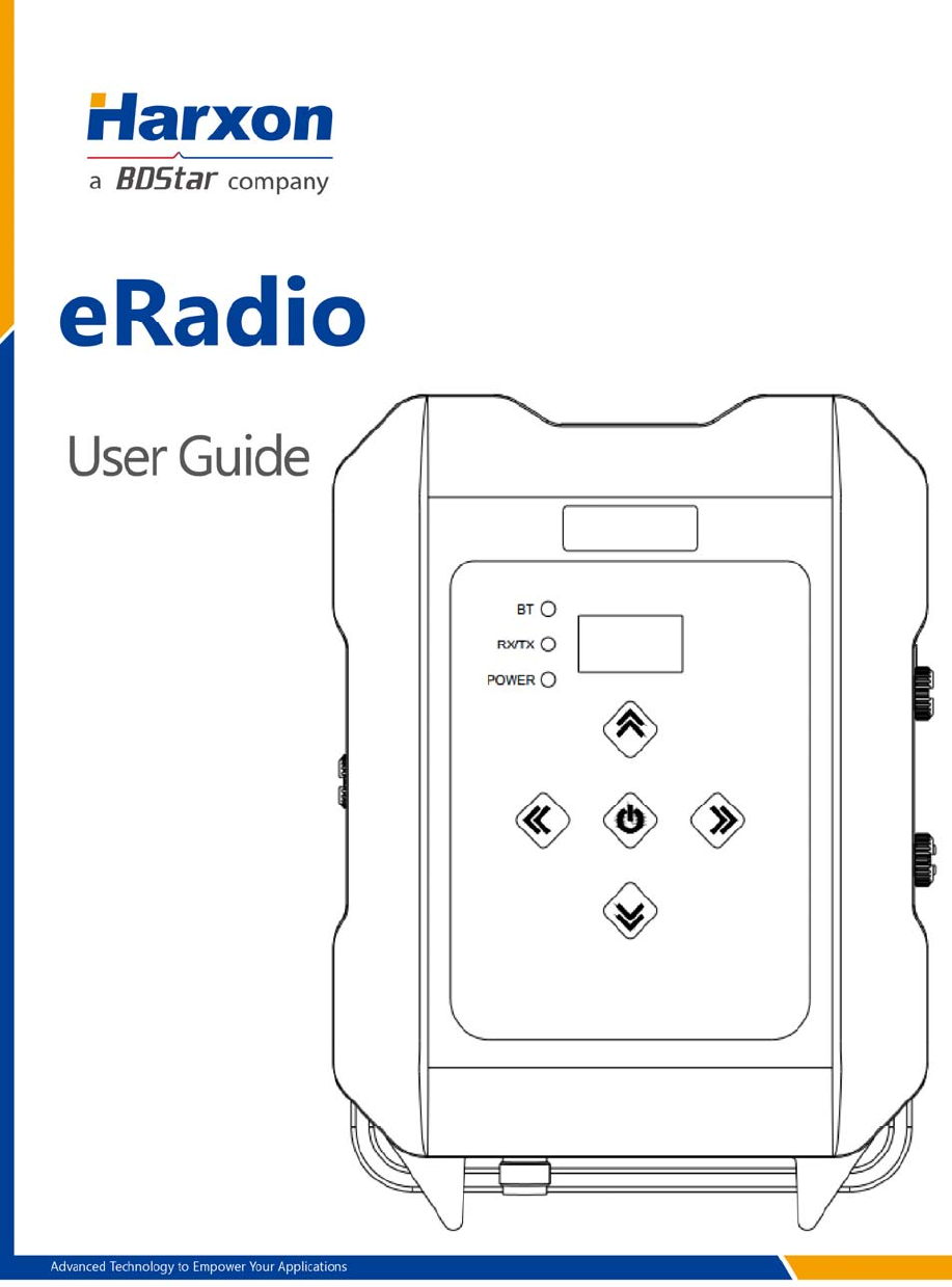
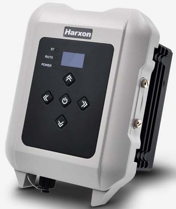
Figure 1 eRadio ........................................................................................................ 9
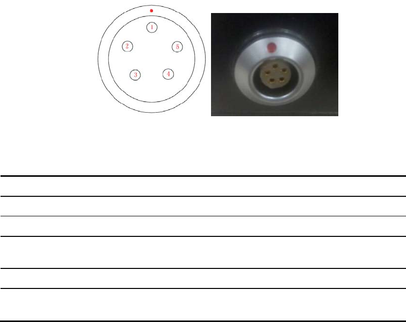
Figure 2 Diagram of eRadio Data Interface ........................................................... 11
Table Index
Table 1 Meanings of Signs in This Manual ............................................................ 7
Table 2 Information of Certification Passed by This Product (supplemented to
be complete) ............................................................................................................. 7
Table 3 eRadio Data Interface Definition .............................................................. 11
Table 4 Specifications and Parameters of Radio ................................................. 28
Table 5 Specifications and Parameters of Bluetooth Module ............................ 29
Table 6 Specifications and Parameters of Network Module② ........................... 29
Table 7 List of Radio Configuration Cable HJ394 Parts ...................................... 30
Table 8 Definition of HJ394 Data Cable B Port ................................................. 31
Table 9 List of Power Cable HJ379 Parts ............................................................. 32
Table 10 eRadio Background Configuration Mode Command Format .............. 33
Table 11 List of eRadio Background Configuration Mode Commands ............. 34

Notice
Meanings of Signs in This Manual
Table 1 Meanings of Signs in This Manual
Sign Meaning Remarks
① Indicate there are notes in the page
for this index/matter
When there are multiple notes in one
page, the number in the sign will
increase.
Some matters requiring users’
attention
Information of Certification Passed by This Product
Table 2 Information of Certification Passed by This Product
Standard Remarks
FCC Rules and Regulations : FCC Part 15B
CE
RED Article3.2 Radio
RED Article3.1(b) EMC
RED Article3.1(a) Safety
RED Article3.1(a) Health
RoHS RoHS Directive 2011/65/EU and its amendment directives –XRF screening test and
Wet Chemical Testing (Lead, Cadmium, Mercury, Hexavalent Chromium, PBBs &
PBDEs content)
REACH
One hundred and seventy three (173) substances in the Candidate List of Substances
of Very
High Concern (SVHC) for authorization published by European Chemicals Agency
(ECHA) on
and before January 12, 2017 regarding Regulation (EC) No 1907/2006 concerning
the REACH
IP67
English Abbreviation A-Z in This Manual
APN Access Point Name
ASCII American Standard Code for Information Interchange
BT Bluetooth
GPS Global Positioning System
IP Internet Protocol

User Service
Common Problem Analysis
If you encounter some technical problems, refer to Section eRadio FAQ in this
manual. This part describes the phenomena, causes and solutions of some
common problems.
Record Information
If the technical problems you encounter are not recorded in the manual, make
a record of the operating environment, use procedure, problem phenomenon
before and after device abnormality, as well as information such as product
model, product hardware version and firmware version.
Product model, product hardware version and firmware version can be queried
through eRadio configuration tools.
This device is a outdoor radio and high power Professional equipment, it need
Professional person to install
Contact Us
Please contact us for more help.
Service Hotline: +86-755-26989948 (8:30-12:00 13:30-18:00)
Sale Hotline: +86-755-86578389 (8:30-12:00 13:30-18:00)
Company Fax: +86-755-26989994
Company Email: sales@harxon.com
1 Introduction
As a type of external transmitting-receiving data radio, eRadio supports many
options of transmitting power, with waterproofing grade up to IP67 and sturdy
and durable structure, applicable for outdoor use under all weather conditions.
eRadio is equipped with 3 bi-color indicator lights (Wireless
transmitting-receiving indicator light: green while receiving, red while
transmitting; Power indicator light: green for normal supply, red for
under-voltage; GPRS and Bluetooth indicator light: green indicator light links
to GPRS, red indicator light links to Bluetooth), one OLED display and five
buttons, convenient for human-computer interaction.
Figure 1 eRadio
1.1 Product Features
Main features of eRadio:
Full-band support, with the frequency point range of 410MHz -470MHz
Many options of transmitting power
Self-adaptive function of serial port baud rate
OLED display
5 user buttons
One-way RS232 interface
Bluetooth module
4G module
3 bi-color status indicator lights
IP67 protection
Note:
Optional component.
1.2 Convention
The following conventions are used in this manual:
The characters following 0x are hexadecimal digits
The characters used by transmitted commands are case insensitive
2 Interface and Component
2.1 Interface of Serial Port Data Cable
The interface of serial port data cable uses the asynchronous serial
communication RS232 standard.
Figure 2 Diagram of eRadio Data Interface
Table 33 eRadio Data Interface Definition
Pin Name Description Remarks
1 VCC Power output DC9-16V
2 GND1 Power Ground
3 RXD Serial port data
receiving RS232 Level
4 GND2 Signal Ground
5 TXD Serial port data
transmitting RS232 Level
2.2 Radio Frequency Interface
The eRadio radio frequency interface uses 50 OHM TNC negative connector.
2.3 Instruction of Indicator Lights
GPRS/BT is GPRS and Bluetooth red and green indicator light, red
indicator light represents GPRS module and green one represents
Bluetooth module;
RX/TX is data transmitting-receiving red and green indicator light, green
indicator light represents data receiving, red indicator light represents data
transmitting;
PWR/ALM is bi-color indicator light for normal power supply and
under-voltage, green indicator light represents normal power supply, red
indicator light represents abnormal voltage;
2.4 Bluetooth Module (Optional)
If the current radio supports Bluetooth, users can configure and query the radio
parameters by the means of Bluetooth, Bluetooth V4.0 is supported;
2.5 Network Module (Optional)
If the current radio supports network data transmission, users can transmit
their data via network, now radio can be used as CORS station, without the
need of RTK device, thus saving cost and simplifying outdoor operation. In
addition, network module supports 4G.
3 Functions and Operation
Instruction
3.1 Startup & Shutdown Button
The startup & shutdown button (power button) can be used to control radio
power-on and power-off, with specific functions as follows:
Short press the startup button for about 1 second to power on, the green
power indicator light illuminates in the case of successful power-on (under
the condition of normal power supply).
Under the condition of power-on, long press the startup button for 3
seconds to power off, the power indicator light goes out and the display is
closed.
The function of menu parameter confirmation
3.2 Left and Right Buttons
You can switch over various function menus through the left and right buttons.
3.3 Up and Down Buttons
In the current menu, you can select the corresponding menu item through the
up and down buttons.
3.4 Data Transmitting-receiving Indicator Light
While transmitting data, the red RX/TX indicator light illuminates; while
receiving data, the green RX/TX indicator light illuminates.
3.5 GPRS and Bluetooth Operating Condition
(Optional)
Include various operating conditions of the GPRS module and Bluetooth
module shown as below, if any module is abnormal, this condition can be
convenient for users to locating the problem:
If GPRS enters the condition of network data transmission successfully,
the green indicator light illuminates constantly;
If GPRS does not detect SIM card, the green indicator light flickers once in
one second;
If GPRS does not access network successfully, the green indicator light
flickers twice in one second;
If GPRS does not connect to the Corse station or server successfully, the
green indicator light flickers three times in one second;
If Bluetooth matches successfully, the red BT illuminates and the Bluetooth
icon appears in the condition, if the offline icon disappears, the BT
indicator light goes out.
3.6 Instruction of Radio Startup and Power Indicator
Light Conditions
Normal radio startup & shutdown has memory function, abnormal radio startup
& shutdown has memoryless function, with specific functions as follows:
In the case of abnormal shutdown for the last time, power on again after
outage, the radio powers on automatically;
In the case of normal shutdown for the last time, only by short pressing for
about 1 second can the radio power on after powering;
If the voltage is lower than the under-voltage threshold value (11.8V by
default, depending on the user’s actual setting value), the red power
indicator light flickers twice in one second;
If the voltage is lower than the forbidden threshold value (11.5V by
default, depending on the user’s actual setting value), the red power
indicator light flickers once in one second;
If the voltage is higher than the under-voltage threshold value (11.8V by
default, depending on the user’s actual setting value), the green power
indicator light illuminates constantly;
When the voltage alarm appears, if it is under-voltage alarm, you need add
0.3V based on the under-voltage threshold value to resume to the normal
voltage operating condition (the green power indicator light illuminates
constantly);
Notes:
Abnormal shutdown means you do not power off by long pressing the
power button, for example, directly disconnecting power;
Normal shutdown refers to power-off by long pressing the power button;
3.7 Device Menu
It is categorized into two types of menus altogether: Basic radio parameter
menu and other features/functions menu.
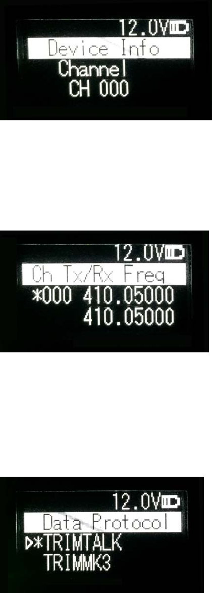
3.7.1 Device Information
In the information column, the current channel number, current transmitting
frequency, current receiving frequency, current protocol, current transmitting
power , device model, firmware version, hardware version and serial number
are displayed.
3.7.2 Transmitting/Receiving Channel and Frequency
In this menu column, you can set up the current transmitting/receiving
frequency, select required communication frequency through up and down
buttons, and press the OK key to select this frequency as the current
communication frequency point, the character of“*”will appear after selection.
3.7.3 Data Protocol
In this menu column, you can set up the current communication protocols such
as TRANSEOT, TRIMTALK and TRIMMK3. Select required communication
protocol through up and down buttons, and press the OK key to select this
protocol as the current communication protocol, the character of“*”will appear
after selection.
Note: After changing the protocol, you need reselect the RF baud rate
supported by the current protocol in the menu of “wireless link rate”;
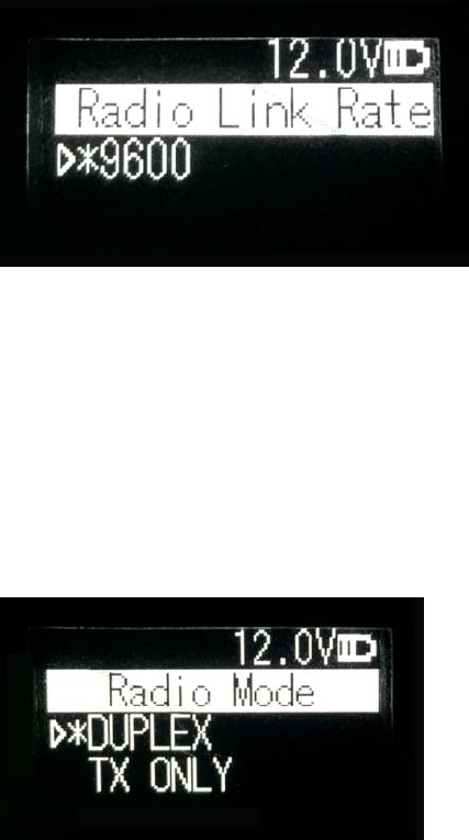
3.7.4 RF Baud Rate
In this menu column, you can set up the current communication RF baud rate.
Different protocols support different types of RF baud rates. For example,
TRANSEOT supports 4800,9600, while TRIMMK3 supports 19200. Select
required RF baud rate through up and down buttons, and press the OK key to
select this RF baud rate as the current communication RF baud rate, the
character of“*”will appear after selection.
3.7.5 Transmitting/Receiving Mode
In this menu column, you can set up the current radio transmitting/receiving
mode. Now, four types of transmitting/receiving modes are supported:
transmitting-receiving, single transmitting, single receiving and relaying mode.
Select required transmitting/receiving mode through up and down buttons, and
press the OK key to select this transmitting/receiving mode as the current
communication transmitting/receiving mode, the character of“*”will appear
after selection.
3.7.6 Transmitting Power
In this menu column, you can set up the current wireless transmitting power
level. Now, three levels of power, high, medium and low, are supported, these
three levels of power values can be customized according to the demands of
users. Select required transmitting power through up and down buttons, and
press the OK key to select this transmitting power as the current
communication transmitting power, the character of“*”will appear after
selection.
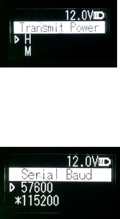
3.7.7 Serial Port Baud Rate
In this menu column, you can set up the current serial port communication
baud rate. Now, there are the following baud rates: 9600, 19200, 38400, 57600,
115200. Select required serial port communication baud rate through up and
down buttons, and press the OK key to select this serial port communication
baud rate as the serial port communication baud rate of the current
communication, the character of“*”will appear after selection.
3.7.8 Serial Port Baud Rate Self-adaption
In this menu column, there are two options: self-adaptive master switch and
triggering enabling. The former has memory function, if turning on the switch,
ON is displayed on the menu; if off, then OFF is displayed; self-adaptive
triggering enabling does not have memory function, the system remains in the
startup condition after power-on; only if the self-adaptive master switch has
been turned on can the adaptive function of serial port baud rate work
normally.
If the serial port baud rate is successfully self-adaptive, a message box pops
up indicating successful self-adaptive matching, meanwhile, self-adaptive
triggering enabling stops automatically. If the serial port baud rate is not
successfully self-adaptive, this function is always operating.
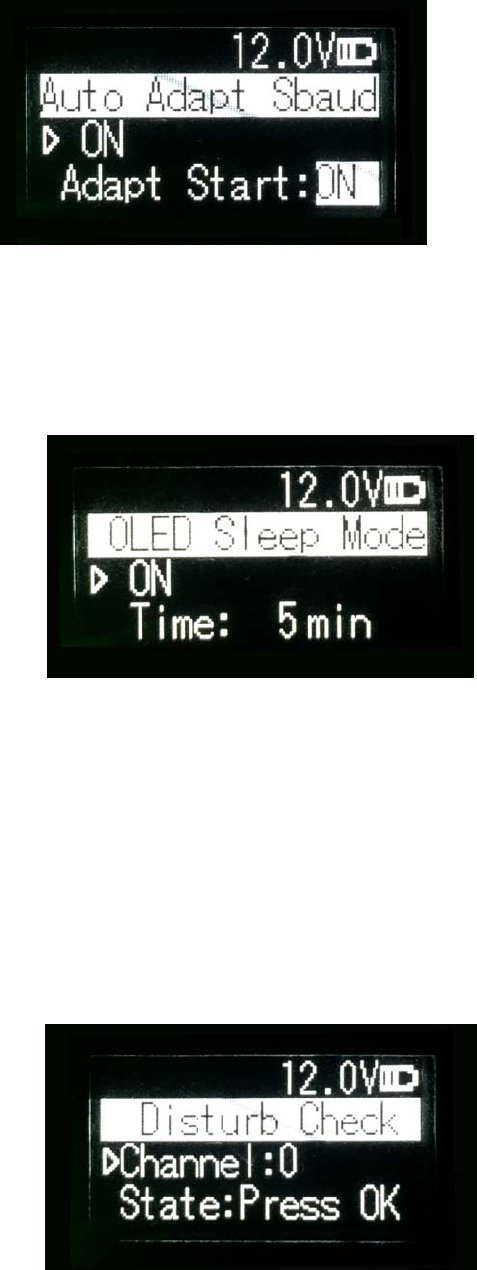
3.7.9 OLED Sleep Mode
Set up whether the OLED display enters sleep, only if the “Function” switch is
in the “On” mode can the OLED display enter the sleep mode, sleep time has
the following levels: 1min, 5min, 10min, 15min, 20min, 25min, 30min.
Note:
After the OLED display enters sleep, you can awaken it through button and
pop-up window message.
3.7.10 Interference Detection
Detect whether there is any interference in the current channel. You can
modify the detection channel number manually and press the OK key for
detection, there are three levels of detection result: superior, moderate, poor.

3.7.11 Language
Set up the display language of device fonts, Chinese and English are
supported for this terminal.
3.8 Use of Radio Configuration Software
Multiple forms of configuring radio parameters are supported. Users can
change and query the current radio parameters by the means of background
mode, user interface mode and PC configuration tool. The use methods of the
PC configuration tool are introduced as below.
The procedures of radio parameters include:
Communication link establishment
Configuration tool installation
Radio parameter query
Radio parameter configuration
3.8.1 Configuration Environment
Firstly, build up the radio parameter configuration environment, devices
needed include: Power supply (12V), power cable (integration of power cable
and data cable), radio, PC. And then, assemble related components according
to Figure 3
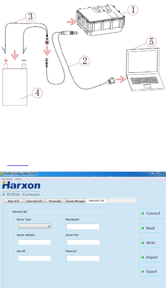
Figure 3 Installation Instruction
3.8.2 Configuration Tool Installation
Open the configuration tool installation file and click “Next” until installation is
completed. In the end, one shortcut appears on the desktop. During the radio
configuration later, you can directly open this shortcut to operate the radio, as
shown in Figure 4.
Figure 4 Radio Query/Configuration Software Interface
Note:
During the use of the configuration tool for radio parameter configuration and query, radio is
not allowed to enter the background parameter configuration mode.
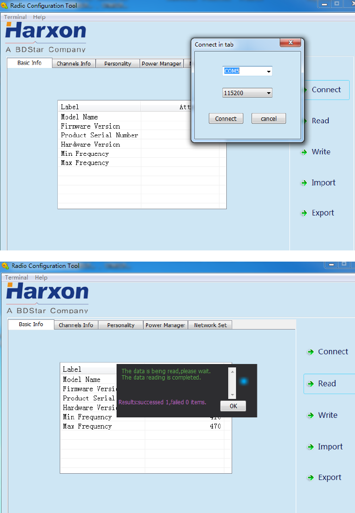
3.8.3 Radio Parameter Query
Firstly, click “Read”, and select the right serial port number and the current
operating radio serial port baud rate in the dialog box popped up, click
“Connect” and “Read” in the end, now you can begin to read the radio
configuration parameters.
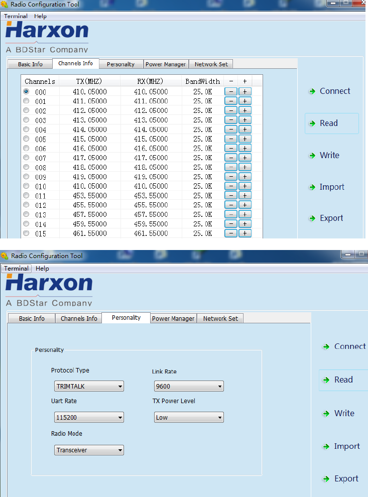
3.8.4 Radio Parameter Configuration
In the basic information column, only radio information can be queried,
settings are not supported;
In the channel information column, the frequency point range set up is
between 410~470MHz, signs‘-’ and ‘+’can be used to increase
and delete or reduce.

In the personalization setting column, users can set up communication
protocol, RF baud rate, serial port baud rate, transmitting power level and
transmitting/receiving mode;
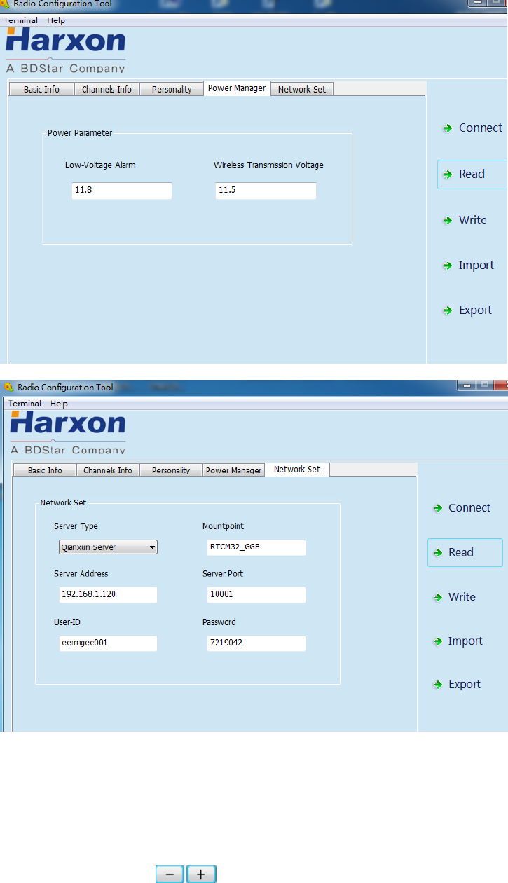
In the power management column, users can set up the low-voltage alarm
threshold value for radio operation and wireless data transmission voltage;
In the network setting column (optional), users can select the
corresponding server type and set up related information such as IP
address, port number and mounting point;
Note:
If the radio does not support GPRS, the settings of related parameters in the network setting
column are invalid; if the operating voltage of the radio is lower than the low-voltage alarm
threshold value, the red power indicator light flickers twice in one second; if the operating
voltage of the radio is lower than wireless data transmission voltage, the radio stops
transmitting user data; when setting up, the low-voltage alarm threshold value must be larger
than wireless data transmission voltage.
3.9 Firmware Upgrade
If the radio runs under the normal operating mode (data transmission mode),
online upgrade for serial port is supported, with the firmware upgrade
procedures as follows:
1. Firstly, use the designated power cable to connect to the big radio, with the
power supply of 9-16V; use the serial port cable (USB to RS232 serial port
cable) to connect to the power cable terminal RS232 male connector,
power on for powering the radio, if the radio has not been powered on,
long press the power button for 3 seconds before power-on, until the
system enters into the normal operating mode
Note:
“RS232”is 232 level, not TTL level. Use USB to serial port cable or RS232 serial port
cable and PC to establish connection.
2. Find the upgrade tool and open the software.
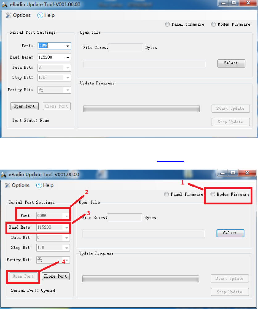
3. Select right serial port number and baud rate, open the serial port and
select internally installed radio, as shown in Figure 5.
Figure 5 Internally Installed Radio Firmware Upgrade Software Connection
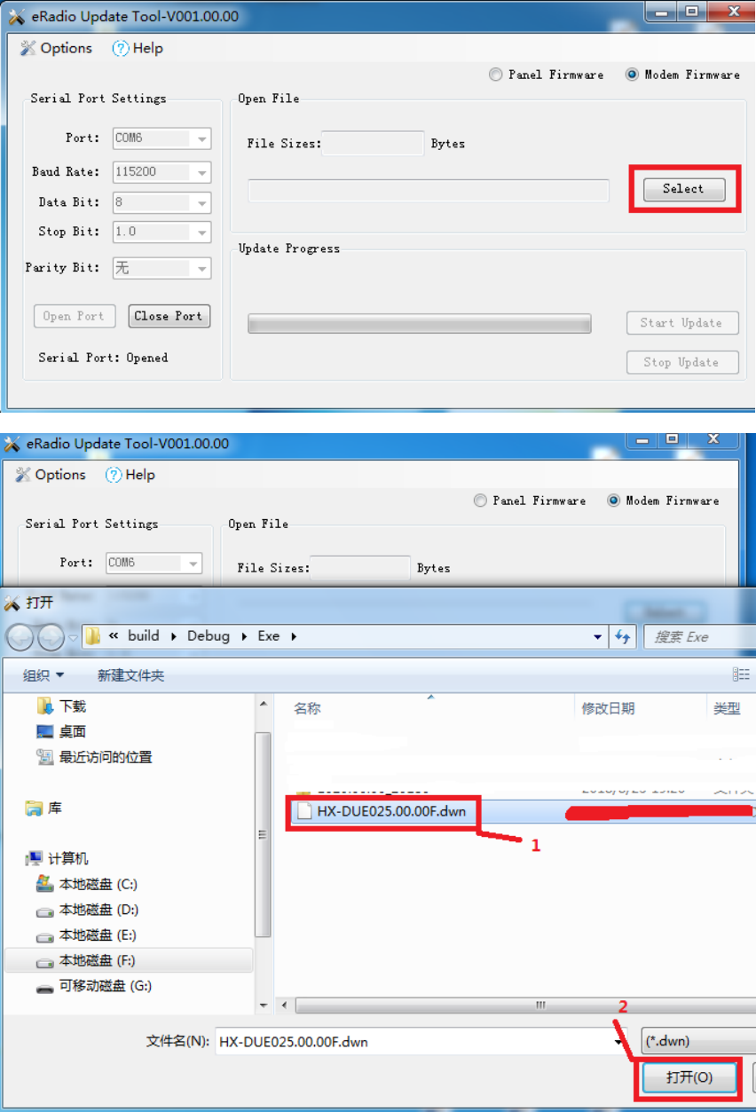
4. Select the file requiring upgrade (e.g.***.**.**F.dwn)
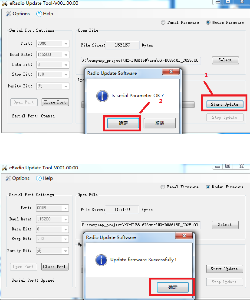
5. Click the “Begin to Update” button (when you click the “Begin to Update”
button, one prompt dialog box pops up indicating whether a parameter is
correct, now users are required to click OK; after that, the system enters
into the upgrade condition immediately)
6. After upgrade, the prompt pops up indicating successful upgrade, click OK
for completion of upgrade this time;
7. The system powers off before powering on again, if the radio has not been
powered on, short press the power button for 1 second before power-on;

Appendix A Technical Indexes
A.1 Specifications and Parameters of Data
Transmission Radio
Table 4 Specifications and Parameters of Radio4
Overall Performance Specification
Specification Name Specification Requirement
Frequency Range 410~470MHz
Operating Mode Transmitting-receiving, single transmitting, single receiving, radio
relaying and network relaying
Channel Interval 25KHz, 12.5KHz
Modulation Mode GMSK/4FSK
Number of Channels 200 editable channels supported
Operating Voltage 9-16V
Power Consumption (Typical
Value)
High transmitting power (28W) 80W@12V DC
Medium transmitting power (22W) 65W@12V DC
Low transmitting power (5W) 35W@12V DC
Standby 3W@12V DC
Frequency Stability <±1ppm
Level of Three Proofings IP67
Dimension 175(L)X130(W)X86.5(H)mm
Weight About 2.0KG
Operating Temperature -40~+65ºC
Storage Temperature -50~+85ºC
Antenna Interface TNC, female connector
Antenna Interface Impedance 50ohm
Data Interface LEMO 5pin
Transmitter Performance Specification
Specification Name Specification Requirement
RF Output Power
High transmitting power
(28W) 44.5±0.5dBm@DC 12V
Medium transmitting power
(22W) 43.5±0.5dBm@DC 12V
Low transmitting power (5W) 37±1dBm@DC 12V
RF Power Stability ±1dB
Adjacent Channel Power >50dB

Receiver Performance Specification
Specification Name Specification Requirement
Sensitivity Superior than -115dBm@BER10-3, 9600bps
Adjacent Channel Selectivity >45dB@25KHz
Stray Disturbance Resistance >45dB
Modem
Specification Name Specification Requirement
RF Rate 4800bps/9600bps/19200bps
Modulation Mode GMSK/4FSK
A.2 Bluetooth Parameters
Table 5 5Specifications and Parameters of Bluetooth Module
Parameter List Value Remarks
Version 4.0 Single-mode Bluetooth
Default Username Serial Number①
Default Password 1234
Transmission Distance 30m Open environment
Operating Temperature -40ºC to +70ºC
A.3 Network Parameters
Table 6 Specifications and Parameters of Network Module6②
Parameter List Value Remarks
2G frequency band GSM 900, DCS1800
3G frequency band FDD B1, B8
4G frequency band FDD B1, B3, B7, B8, B20
Note:
The username should not be longer than 12 characters in length, the serial number here
is different with the internal serial number of machine.
Because communication network involves with multiple frequency bands, all frequency
bands should not be covered for the same product, if the current parameters cannot meet
your requirements, Please contact us for more help.
A.4 eRadio Suite Parts
A.4.1 Radio Configuration Cable (HJ394) (Optional)
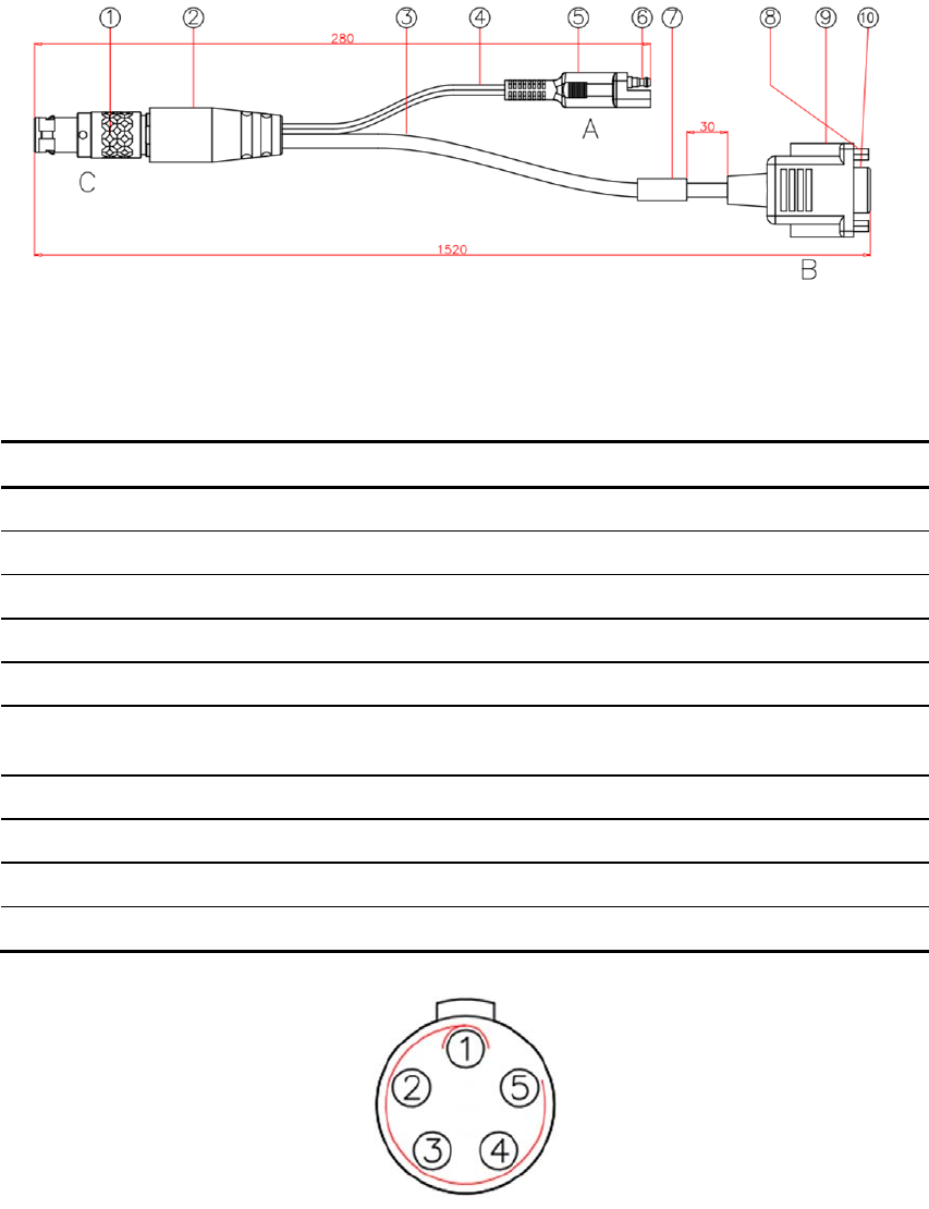
Figure 6 Structure and Dimension of External Data Transmission Radio Configuration
Cable HJ394
Table 77 List of Radio Configuration Cable HJ394 Parts
Mark Explanation Remarks
1 Plug 1BHTN05P
2 Rubber Coating Black
3 Cable Black
4 Cable Black
5 Rubber Coating Black
6 Bullet Terminal 1 male connector and 1 female
connector respectively
7 Label MI-RD-HJ394 as the content
8 Screw with Internal Thread
9 Rubber Coating Black
10 Plug DB9 female connector
Figure 7 HJ394 C Port Welding Surface View
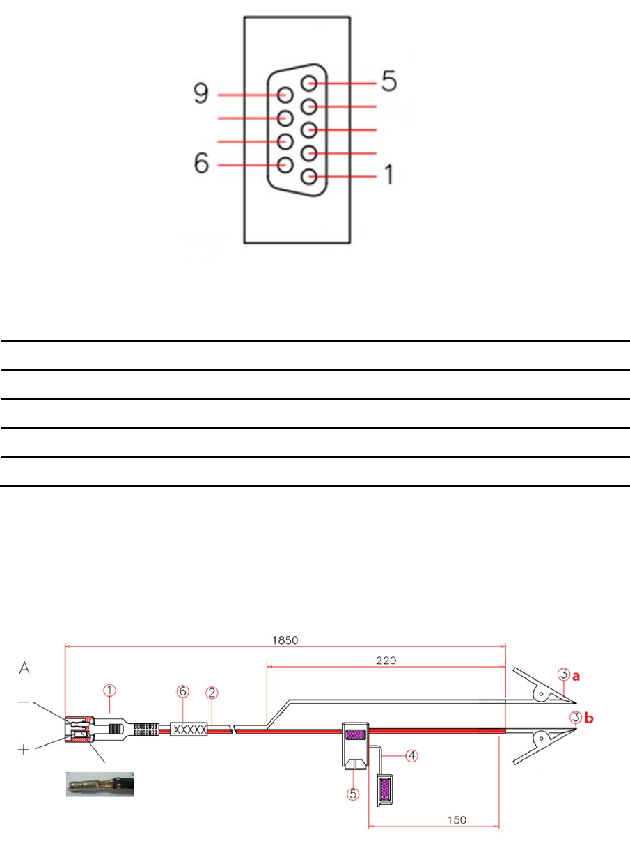
Figure 8 HJ394 B Port Welding Surface View
Table 88 Definition of HJ394 Data Cable B Port
Pin Name Description Remarks
2 TXD Output
3 RXD Input
5 GND GND
1,4,6,7,8,9 RSV Reserved
Note:
After connecting to the DB9 port on PC, this port can communicate normally.
A.4.2 Power Cable (HJ379)
Figure 9 Structure and Dimension of Power Cable HJ379

Table 9 List of Power Cable9 HJ379 Parts
Mark Explanation Remarks
1 Bullet Terminal 1 male connector and 1
female connector
respectively
2 Double-row cable Black
3 a: Black alligator clip, b: Red alligator clip
4 Fuse Support 1 male connector and 1
female connector
respectively
5 Fuse 32V/15A
6 Label MI-RD-HJ379 as the content

Appendix B Command
eRadio includes the following operating modes:
Normal operating mode
Background configuration mode
Configuration tool configuration mode
Upgrade firmware mode
1. Normal operating mode
Under the normal operating mode, the radio can carry out data
transmission;
2. Background configuration mode
Firstly, the radio must run under the normal operating mode, and then
send the command of entering into the background configuration mode
(0x21 0x57 0x84 0x43 0x6c 0xa7 0x4e 0x5f) to enter into the configuration
mode, send the command of exiting from the configuration mode (ATA\r\n)
to exit from the configuration mode, return to the normal operating mode;
3. Configuration tool configuration mode
Firstly, the radio must run under the normal operating mode, and then
configure and read the radio parameters with the matched upper computer
configuration tool;
4. Firstly, the radio must run under the normal operating mode, and then
upgrade the radio firmware with the matched upgrade software;
Under the background configuration mode, configure and query the
command format of radio parameters; except the command of entering
into configuration that does not end with“\r\ n”, other commands must end
with“\r\ n”, the format of eRadio command is shown in Table 22:
Table 1010 eRadio Background Configuration Mode Command Format
1. Configure radio parameter format
Command Space Character
(0x20) Parameter Ending Character
2. Response format
Ending
Character PROGRAMMED
OK Ending
Character >
3. Query radio parameter format
Command Ending Character

For example, configure the current radio transmitting frequency point as
460.125Mhz:
The format is shown as below: TX 460.0125\r\n; response format:
\r\nPROGRAMMED OK \r\n>
Query the current radio transmitting frequency point:
The format is shown as below: TX\r\n; response format: \r\nTX 460.01250
MHz\r\n>
Table 1111 List of eRadio Background Configuration Mode Commands
Command
Name Command Format Response Format Explanation
Enter into
the
configuration
mode
21 57 84 43 6c a7 4e
5f \r\n into config\r\n
Indicate the radio has
entered into the
configuration mode, the
command of entering is
hexadecimal
Exit from the
configuration
mode ATA\r\n \r\n exit config\r\n Exit from the configuration
mode and enter into the
normal operating mode
Query the
current
receiving
frequency
point
rx\r\n
\r\n RX receiving
frequency point
MHz\r\n>
e.g.: \r\n\r\n RX
456.05000 MHz\r\n>
Indicate the current
receiving frequency
point is 456.05MHz;
One space character is
between “RX” and “receiving
frequency point” for
separation; “receiving
frequency point” has 9
characters in length; One
space character is between
“receiving frequency point”
and “MHz” for separation;
Set up the
current
receiving
frequency
point
rx receiving
frequency point\r\n
e.g.:
rx 456.05\r\n
Indicate setting up
the current receiving
frequency point as
456.05MHz;
\r\nPROGRAMMED
OK\r\n>
Indicate the current
receiving frequency
point is written
successfully
One space character is
between the strings
PROGRAMMED and OK for
separation;
Settable range of
receiving frequency point is:
410≦RX≦470
Query the
current
transmitting
frequency
point
tx\r\n
\r\n TX transmitting
frequency point
MHz\r\n>
e.g.: \r\n\r\n TX
456.05000 MHz\r\n>
Indicate the current
transmitting frequency
One space character is
between “TX” and
“transmitting frequency
point” for separation;
“transmitting frequency
point” has 9 characters in
length; One space
character is between
4. Response format
Ending
Character Command Space
Character Query Result Ending
Character >

Command
Name Command Format Response Format Explanation
point is 456.05MHz; “transmitting frequency
point” and “MHz” for
separation;
Set up the
current
transmitting
frequency
point
tx transmitting
frequency point \r\n
e.g.:
tx 456.05\r\n
Indicate setting up
the current
transmitting
frequency point as
456.05MHz;
\r\nPROGRAMMED
OK\r\n>
Indicate the current
transmitting frequency
point is written
successfully
One space character is
between the strings
PROGRAMMED and OK for
separation;
Settable range of
transmitting frequency point
is:
410≦TX≦470
Current
protocol
query prt\r\n
\r\n PRT protocol
type\r\n>
e.g.: \r\nPRT
TRIMTALK\r\n>
Indicate the current
radio protocol is
TRIMTALK
While querying protocol,
return the name of the
current radio work protocol;
Note: One space
character is between the
strings “PRT” and “protocol
type” for separation;
“protocol type” has 8
characters in length, if the
name of the current protocol
type has less than 8
characters in length, use
space characters to fill; for
example, for protocol
SOUTH, there are 5
characters, 3 space
characters are additionally
needed;
Current
protocol
setting
prt protocol type\r\n
e.g.: prt TRIMTALK
\r\n
Indicate setting up
the current radio
work protocol as
TRIMTALK
\r\nPROGRAMMED
OK\r\n>
Indicate the current
radio protocol is written
successfully
Names of common
protocols:
TRANSEOT (equivalent to
transparent), TT450S,
TRIMTALK;
RF baud
rate query baud\r\n
\r\nBAUD RF baud
rate\r\n>
e.g.: \r\nBAUD 9600
\r\n>
Indicate the current
radio RF baud rate is
9600
One space character is
between “BAUD” and “RF
baud rate” for separation;
“RF baud rate” has 6
characters in length, if the
current RF baud rate has
less than 6 characters in
length, use space characters
to fill; for example, for RF
baud rate of 9600, there are
only 4 characters, 2 space
characters are additionally
needed;

Command
Name Command Format Response Format Explanation
RF baud
rate setting
baud protocol
type\r\n
e.g.: baud 9600\r\n
Indicate setting up
the current radio RF
baud rate as 9600
\r\nPROGRAMMED
OK\r\n>
Indicate the current
radio RF baud rate is
written successfully
Operating
mode query
mode\r\n
\r\nMODE operating
mode\r\n>
e.g.: \r\nMODE
DUPLEX\r\n>
Indicate the current
radio operating mode
is
transmitting-receiving
One space character is
between “MODE” and
“operating mode” for
separation; “operating
mode” has 8 characters in
length, if the operating mode
currently displayed has less
than 8 characters in length,
use space characters to fill;
for example, for operating
mode of duplex, there are
only 6 characters, 2 space
characters are additionally
needed;
Operating
mode setting
Mode operating
mode\r\n
e.g.: mode duplex\r\n
Indicate setting up
the current radio
operating mode as
transmitting-receiving
\r\nPROGRAMMED
OK\r\n>
Indicate the current
radio operating mode
is written successfully
The operating modes
supported are:
DUPLEX
(transmitting-receiving),
TXONLY (single
transmitting), RXONLY
(single receiving), RPT
(radio relaying mode),
NETRPT (network relaying
mode)
Transmitting
power query
pwr\r\n
\r\nPWR power
level\r\n>
e.g.: \r\nPWR L\r\n>
Indicate the current
radio transmitting
power is 5W
The corresponding relations
among power levels:
H-28W;M-22W;L3-5W;
One space character is
between “PWR” and “power
level” for separation;
“power level” has 1
characters in length
Transmitting
power
setting
pwr power level\r\n
e.g.: pwr L\r\n
Indicate setting up
the current radio
transmitting power as
5W
\r\nPROGRAMMED
OK\r\n>
Indicate the current
radio transmitting
power is written
successfully
Serial port
baud rate
query
sbaud\r\n
\r\nSBAUD serial port
baud rate\r\n>
e.g.: \r\nSBAUD
115200\r\n>
Indicate the current
radio serial port baud
The list of serial port baud
rates supported is shown as
below:
9600,
19200,38400,57600,115200;
One space character is

Command
Name Command Format Response Format Explanation
rate is 115200 between “SBAUD” and
“serial port baud rate” for
separation; “serial port
baud rate” has 6 characters
in length, if the serial port
baud rate currently displayed
has less than 6 characters in
length, use space characters
to fill; for example, for serial
port baud rate of 9600, there
are only 4 characters, 2
space characters are
additionally needed;
Serial port
baud rate
setting
sbaud serial port
baud rate\r\n
e.g.: sbaud
115200\r\n
Indicate setting up
the current radio
serial port baud rate
as 115200
\r\nPROGRAMMED
OK\r\n>
Indicate the current
radio serial port baud
rate is written
successfully
Current work
channel
query
channel\r\n
e.g.: channel 000\r\n
Indicate the current
work is done at
Channel 0
\r\n channel channel
number\r\n>
e.g.: \r\n channel
000\r\n>
Indicate the current
work is done at
Channel 0
The channel number has 3
characters in length
Current work
channel
setting
channel channel
number\r\n
e.g.: channel 0\r\n
Indicate setting up
current work at
Channel 0
\r\nPROGRAMMED
OK\r\n>
Indicate the current
channel number is
written successfully
The channel number must
be less than the number of
maximum supported
channels
Software
version
query
srev\r\n
\r\n software
version\r\n
e.g.: \r\n
E025.00.00\r\n >
Indicate the current
radio software version:
E025.00.00
“software version”; has 12
characters in length, fill with
space characters for lacking
of characters;
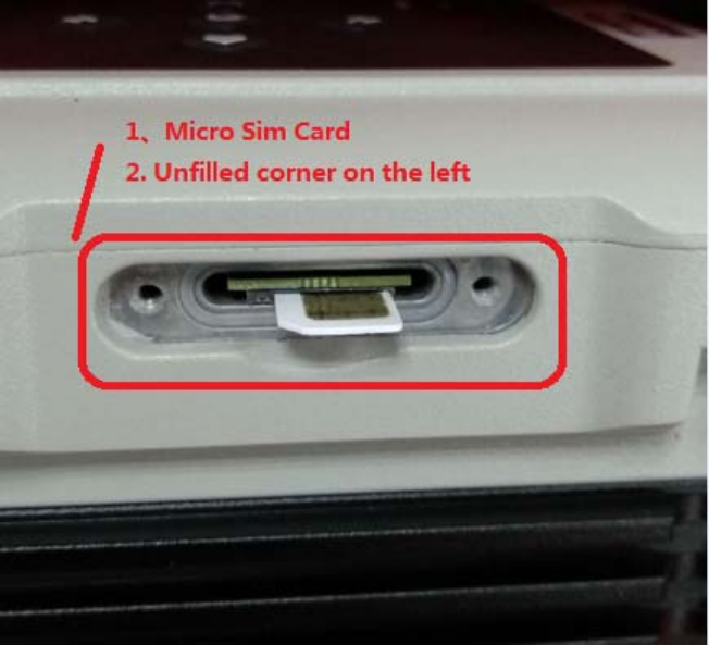
Appendix C eRadio SIM Setup

Appendix D eRadio FAQ
Failure Description Cause Analysis Solutions
Failing to power on
Unreliable power cable
connection (external
power supply);
The positive and
negative poles reversed
(external power supply);
If external power supply is
used, connect to the power
cable correctly, with the
rated working voltage of
DC12V;
Wiring based on the correct
positive and negative poles;
The configuration tool
cannot read or set up
parameters
Incorrect serial port
parameter configuration;
The existing serial port
for communication
occupied
Select the serial port
number, serial port baud
rate, 8 data bits, 1 stop bit,
no odd-even check, no data
flow control correctly;
Replace the existing serial
port number
Failing to sending data
Inconsistent
communication
parameter configuration
of the
receiving/transmitting
terminal;
No external antenna for
radio;
Make communication
parameter configuration of
the receiving/transmitting
terminal consistent
(receiving/transmitting
frequency point,
communication protocol, RF
baud rate, operating mode);
If the radio has no external
antenna, select appropriate
antenna according to the
frequency band range;
The red GPRS indicator
light flickers twice in one
second
Failing to insert the SIM
card or insert it well;
GPRS module
abnormality
Install the SIM card
correctly;
Report for repair
FCC Statement
FCC Caution
§ 15.19 Labeling requirements.
This device complies with part 15 of the FCC Rules. Operation is subject to the following
two conditions: (1) This device may not cause harmful interference, and (2) this device
must accept any interference received, including interference that may cause undesired
operation.
§ 15.105 Information to the user.
Note: This equipment has been tested and found to comply with the limits for a Class B
digital device, pursuant to part 15 of the FCC Rules. These limits are designed to provide
reasonable protection against harmful interference in a residential installation. This
equipment generates uses and can radiate radio frequency energy and, if not installed
and used in accordance with the instructions, may cause harmful interference to radio
communications. However, there is no guarantee that interference will not occur in a
particular installation. If this equipment does cause harmful interference to radio or
television reception, which can be determined by turning the equipment off and on, the
user is encouraged to try to correct the interference by one or more of the following
measures:
-Reorient or relocate the receiving antenna.
-Increase the separation between the equipment and receiver.
-Connect the equipment into an outlet on a circuit different from that to which the receiver
is connected.
-Consult the dealer or an experienced radio/TV technician for help.
§ 15.21 Information to user.
Any Changes or modifications not expressly approved by the party responsible for
compliance could void the user's authority to operate the equipment.
This equipment complies with FCC radiation exposure limits set forth for an
uncontrolled environment. This equipment should be installed and operated with
minimum distance 2m between the radiator & your body.