HBC radiomatic M50004 Micron 5 User Manual BE MICR5 3 V2 1
HBC-radiomatic GmbH Micron 5 BE MICR5 3 V2 1
User Manual
Operating Instructions
Radio Transmitter micron 5-3
BE-MICR5-3_V2-1.DOC [ Word 2000 ] US Page 1 / 18
HBC-radiomatic GmbH • D-74564 Crailsheim • GERMANY
Information and specifications subject to change without notice. 02-13-2002
Radio Control System
HBC – Radio Control
R
Ra
ad
di
io
o
T
Tr
ra
an
ns
sm
mi
it
tt
te
er
r
m
mi
ic
cr
ro
on
n
5
5-
-3
3
FCC ID: NO9M50004

Operating Instructions
Radio Transmitter micron 5-3
Page 2 / 18 BE-MICR5-3_V2-1.DOC [ Word 2000 ] US
HBC-radiomatic GmbH • D-74564 Crailsheim • GERMANY
02-13-2002 Information and specifications subject to change without prior notice.
Radio Control System
Manufacturer: HBC-radiomatic GmbH
Haller Strasse 49 - 53
74564 Crailsheim • Germany
Tel. +49 ( 0 ) 79 51 – 3 93 - 0
Fax +49 ( 0 ) 79 51 – 3 93 – 50
E-mail: info@radiomatic.com
http://www.hbc-radiomatic.com
HBC-radiomatic GmbH is not liable for any misprints or errors! – All rights reserved.
™ radiomatic is a registered German trademark.
© 2002 – 02 , HBC-radiomatic GmbH , D-74564 Crailsheim, Germany
No part of any software or of the present document may be reproduced in any manner whatsoever without
the expressed written permission of HBC-radiomatic GmbH.

Operating Instructions
Radio Transmitter micron 5-3
BE-MICR5-3_V2-1.DOC [ Word 2000 ] US Page 3 / 18
HBC-radiomatic GmbH • D-74564 Crailsheim • GERMANY
Information and specifications subject to change without notice. 02-13-2002
Radio Control System
Table of Contents
1 Description ...................................................................................4
2 Safety Instructions........................................................................5
2.1 Pictographs....................................................................................... 5
2.2 General Safety Instructions................................................................ 6
2.3 Operator Safety Instructions.............................................................. 7
3 Operation......................................................................................8
Activating the transmitter .................................................................. 8
Frequency Selector (Scanner)............................................................ 9
Transmitter Inscription .................................................................... 10
3.1 Battery and Battery Charger............................................................. 11
3.1.1 FuB 3A Transmitter Battery................................................. 11
3.1.2 FLG 105 Battery Charger..................................................... 11
4 Fault Correction..........................................................................12
5 Maintenance................................................................................13
5.1 In the Event of a Fault...................................................................... 13
6 Technical Data............................................................................14
Dimensions...................................................................................... 15
6.1 Accessories..................................................................................... 16
7 Certificates and Approvals .........................................................17

Operating Instructions
Radio Transmitter micron 5-3
Page 4 / 18 BE-MICR5-3_V2-1.DOC [ Word 2000 ] US
HBC-radiomatic GmbH • D-74564 Crailsheim • GERMANY
02-13-2002 Information and specifications subject to change without prior notice.
Radio Control System
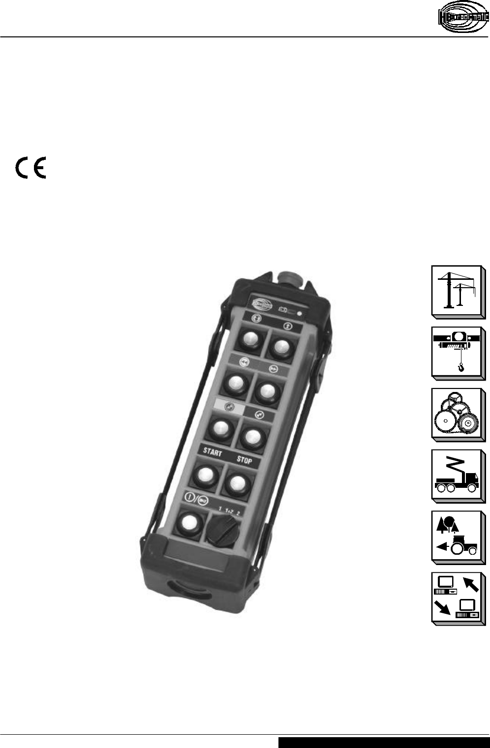
1 Description
The micron 5-3 transmitter is designed to transmit command instructions for controlling industrial
cranes and hoists as well as operating machines and plants.
Depending on the type and version selected, up to 14 control commands plus the
integrated safety commands are available to the operator.
A non-interchangeable system address ensures the functional safety of the radio control
system when operating cranes or machines. This feature is particularly important when
several cranes or machines are in use, for example in halls and shops. The system
address is exclusively allocated to each HBC radio transmitter and its respective
receiver.
It is not possible to activate crane or machine functions using a radio control
system allocated to another crane or machine.
The transmitter has general telecommunications approvals. It is not necessary to have
or to apply for a license to operate the transmitter with the respective receiver. The
transmitter broadcasts in either a 30 cm or 70 cm bandwidth. The transmitter is equipped
with < 5 mW or < 10 mW transmitting power.
Operating the transmitter using a different frequency range or transmitting power
requires the approval of the competent regulative authorities for telecommunication.
High-quality radio technology pursuant to the guidelines laid down by the German
Regulative Authorities for Telecommunications and Postal Services and the Regulations
For The Prevention of Accidents combined with perfected microprocessor technology
guarantees the highest degree of operative safety, service quality and serviceable life.
Operating Instructions
Radio Transmitter micron 5-3
BE-MICR5-3_V2-1.DOC [ Word 2000 ] US Page 5 / 18
HBC-radiomatic GmbH • D-74564 Crailsheim • GERMANY
Information and specifications subject to change without notice. 02-13-2002
Radio Control System
2 Safety Instructions
2.1 Pictographs
The following pictographs will be used throughout the present operating instructions :
Indicates a possible shock hazard
Contacting components under voltage may lead to death. Housing (e.g. hoods and
lids) marked with this symbol may only be opened by qualified electricians after
having disconnected the device from the mains supply (supply voltage, operating
voltage or input terminal voltage).
Indicates safety relevant passages
You will find this pictograph as an indicator for occupational safety measures. The
neglecting of such measures poses a serious hazard.
Always observe the instructions and be particularly attentive and careful.
Avoid any situations that could at any time be a danger to persons or machines.
Indicates important information
This symbol brings your attention to important information on how to secure a long
serviceable life of the radio control system.
Pay attention to the comments and instructions given. Ignoring the information
provided may permanently impair the reliability and operability of the equipment.

Operating Instructions
Radio Transmitter micron 5-3
Page 6 / 18 BE-MICR5-3_V2-1.DOC [ Word 2000 ] US
HBC-radiomatic GmbH • D-74564 Crailsheim • GERMANY
02-13-2002 Information and specifications subject to change without prior notice.
Radio Control System
2.2 General Safety Instructions
Radio control systems facilitate and increase the operating efficiency of cranes and
machines. Nevertheless, the operator must thoroughly understand and be in a position
to properly use a radio control system !
Ø Read the Operating Instructions Manual carefully and thoroughly before working with
the transmitter for the first time !
Ø The operator undertakes to strictly adhere to the instructions and proceedings
described in this manual as well as to follow the general rules and regulations for
worker safety and accident prevention. Ignoring any such instructions or regulation
could pose a fatal threat to the operator or others.
Ø Keep this manual on location and readily available at all times !
Ø Only authorized and properly trained personnel may operate the radio control
system.
Ø Anyone who is under the influence of drugs, alcohol or medication that has a
detrimental effect on a person's reactions may at no time commission, operate,
maintain or repair the transmitter.
Ø Before switching the transmitter ON ensure that no-one is or can be endangered by
the initiated operation.
Ø With the first signs of any malfunction related to the operative safety and reliability
of the device the operator must immediately shut down or not activate the
transmitter. For the purpose of the present manual "shut down" implies :
– switching OFF the transmitter,
– storing the transmitter in a safe place and ensuring no unauthorized access,
– de-energizing the receiver,
– unplugging the connection cable on the receiver !
Ø Defects must be repaired and objects of interference must be removed immediately !
Ø A defective transmitter may only be repaired by qualified and competent personnel.
Use only original HBC spare parts. The use of any other spares will render the
technical inspectorate approval invalid as well as substantially impede operative
safety.
Ø Observe all periodical tests and inspections that are required by law or
recommended in the present operating instructions !
Ø When using the transmitter always observe the regulations and instructions
stipulated in the authoritative worker safety and accident prevention regulations.
– The transmitter has been manufactured in accordance with the regulations and
guidelines stipulated in the German Trade Association's "Safety and Accident
Prevention Regulations for Operating Cranes by Radio Controls" (VBG 9) and pr
EN 12077-1.
– The transmitter has been tested and approved in accordance with EMC
guidelines and complies with the authoritative standards for emitted interference
and interference immunity.
Ø Use the transmitter cautiously and properly. In particular when using a transmitter to
radio control a machine or crane for the first time.
Operating Instructions
Radio Transmitter micron 5-3
BE-MICR5-3_V2-1.DOC [ Word 2000 ] US Page 7 / 18
HBC-radiomatic GmbH • D-74564 Crailsheim • GERMANY
Information and specifications subject to change without notice. 02-13-2002
Radio Control System
2.3 Operator Safety Instructions
Ø Before beginning crane operation, position yourself so that you have a clear and
complete overview of the working radius of the crane or machine.
Ø Use the enclosed belt-clip to carry the transmitter. To operate, hold the transmitter
securely in your hand. Use the wrist strap. Follow these instructions to ensure
personal safety.
Ø Depending on your angle or position to the crane or machine, the transmitter control
commands "trolley left" and "trolley right" appear to interchange ! It is essential that
you take your bearings to the crane or machine into due consideration before
operating equipment.
Ø In case of an emergency or any disturbances within the working range of the crane
or machine, switch the transmitter OFF immediately by pressing the STOP
pushbutton. Should the transmitter show signs of technical failure or breakdown,
disconnect the radio control system immediately !
Ø Switch the transmitter OFF during breaks and after finishing work to avoid any
misoperation of crane or machine by unintended activation of the operator controls.
– These precautions are particularly important whenever changing your position or
climbing over an obstacle.
Ø Never leave an activated transmitter unattended. The operator undertakes to follow
and comply with the authoritative regulations for worker safety and accident
prevention.
Note :
In the event of an interruption of the radio link during a working cycle – what can
occasionally happen – both transmitter and receiver automatically shut down (so-
called "compulsory switch-off").
To reactivate the system release all operator controls, such as pushbuttons, and
allow the control elements to return to their zero position. Press the pushbutton.
The system must be reactivated before the crane or machine can react to control
commands ! This feature hinders any uncontrolled or unwanted crane or machine
movement, should the radio link be interrupted.
Operating Instructions
Radio Transmitter micron 5-3
Page 8 / 18 BE-MICR5-3_V2-1.DOC [ Word 2000 ] US
HBC-radiomatic GmbH • D-74564 Crailsheim • GERMANY
02-13-2002 Information and specifications subject to change without notice.
Radio Control System
+
_
31.379
31.292
File: MIC5-3_W.CDR [ CorelDraw 8.0 ] 14.11.2001 US
START STOP
Á
À
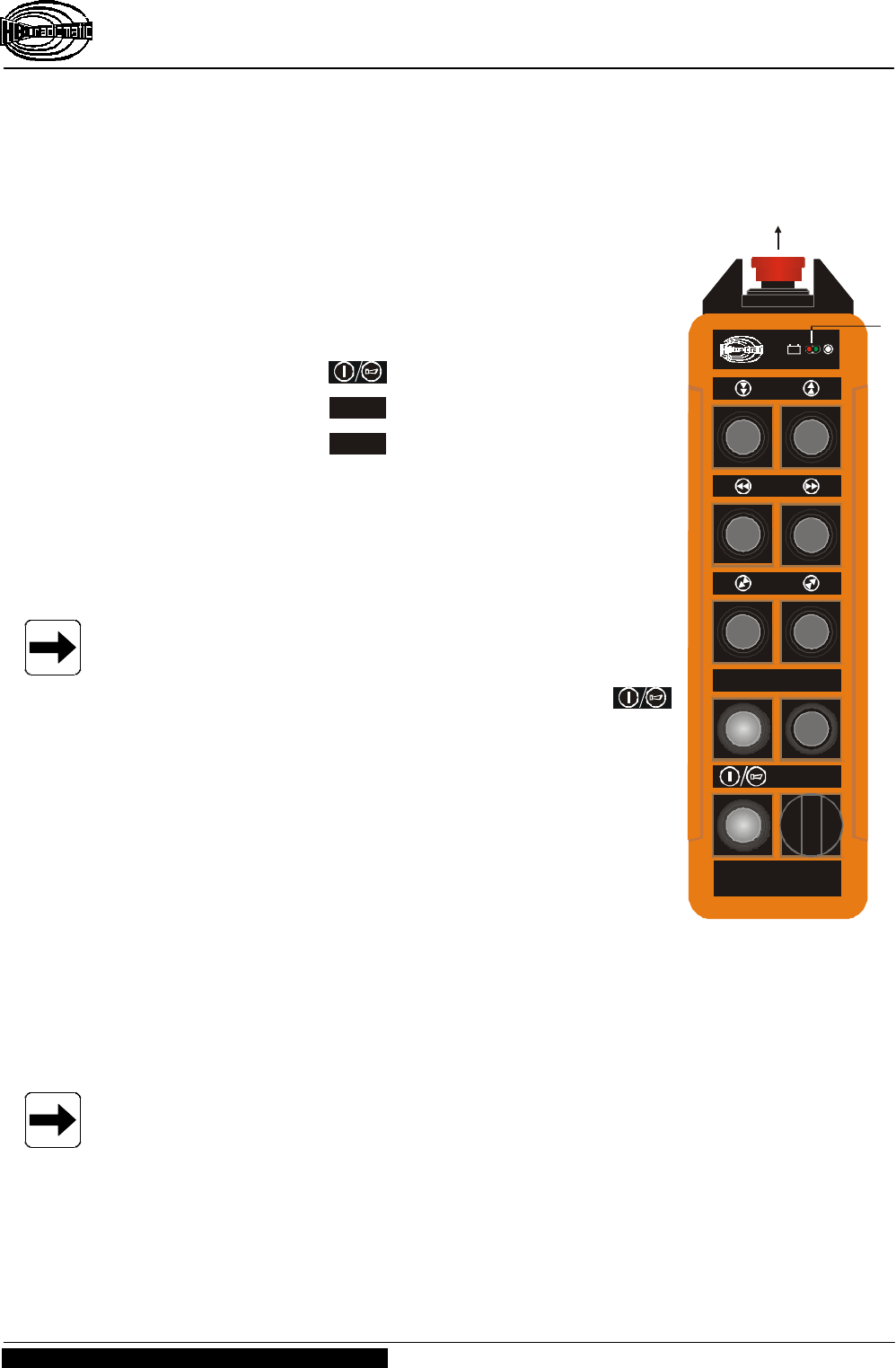
3 Operation
Activating the transmitter
1. Make sure that the STOP push button • is released.
2. Insert a charged battery into the battery compartment.
Inscription must be visible.
3. Press and release button.
4. Press and release STOP button.
5. Press and release START button.
The display ‚ will blink green. The transmitter is now ready
to operate.
Please note: Input has to occur within 6 seconds.
Note :
After switching ON the transmitter and before operating the
crane or machine you must always :
– Trigger the acoustic signal by pressing the
button this warns all colleagues that the crane or
machine is about to move.
– Test the operativeness of the transmitter using the
STOP push button À.
After switching ON the transmitter the instrument indicates a
successful radio link to the receiver when the red LED
"HF/RF/H.F./HF" extinguishes and the green LED "Si 1" lights
up (refer to control light panel on receiver), i.e. the radio
control system is now operative. The operator can now issue
control commands using the transmitter control elements.
When the battery is nearly empty, the display ‚ lights up red or an acoustic signal
sounds. The drained battery must be immediately replaced by a fully charged battery
and then inserted into the battery charger for recharging (refer to chapter "Battery and
Battery Charger" for further details).
Note :
The transmitter will automatically switch off within a few minutes if the operator fails
to replace the drained battery.
Should the operator switch OFF the transmitter with the STOP push button À, release
the STOP push button and restart the transmitter according to the instruction above.
Operating Instructions
Radio Transmitter micron 5-3
BE-MICR5-3_V2-1.DOC [ Word 2000 ] US Page 9 / 18
HBC-radiomatic GmbH • D-74564 Crailsheim • GERMANY
Information and specifications subject to change without notice. 02-13-2002
Radio Control System
For safety reasons we have equipped the transmitter with an automatic switch OFF
(APO = Automatic Power Off function). The transmitter is automatically put out of circuit
after 15 minutes of non-use.
The automatic power OFF also saves battery power.
Note:
The automatic switch-OFF (APO function) does not relieve the operator of his
responsibility to turn OFF the transmitter when not in use !
Option rotary switch
With the optional 3-step rotary switch 2 hoisting gears or 2 trolleys can be operated.
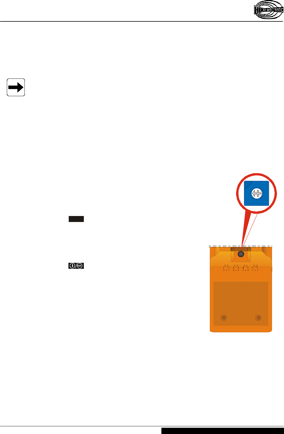
Frequency Selector (Scanner)
In the event that a particular channel is being used by
another operator, the transmitter can be switched to a
different channel by means of the rotary selector switch
located inside the transmitter (4 frequencies). The receiver
scanner automatically adjusts the receiver to the selected
radio frequency.
Changing radio control system frequencies
1. Press STOP button to switch off the transmitter.
2. Remove protective cap from the back of the transmitter.
3. To select a new frequency, use a screwdriver (size 0)
and turn the switch clockwise (one step).
4. Replace protective cap.
5. Press button to switch on the transmitter.
The receiver automatically resets the system to the new
frequency selected in less than a second.
Battery compartment
Remove
protective
cap first !
0 - 3
4 - 7
8 - B
C - F
= Frequency 1-4 with APO
= Frequency 1-4 without APO
= Frequency 1-4, with APO
= Frequency 1-4,
without APO
File: MIC5-3_I_APO-FrequenzWahl.CDR [ CorelDraw 8.0 ] 2000-08-16 FL
0
1
2
3
4
5
6
7
8
9
A
B
C
D
E
F
Operating Instructions
Radio Transmitter micron 5-3
Page 10 / 18 BE-MICR5-3_V2-1.DOC [ Word 2000 ] US
HBC-radiomatic GmbH • D-74564 Crailsheim • GERMANY
02-13-2002 Information and specifications subject to change without notice.
Radio Control System
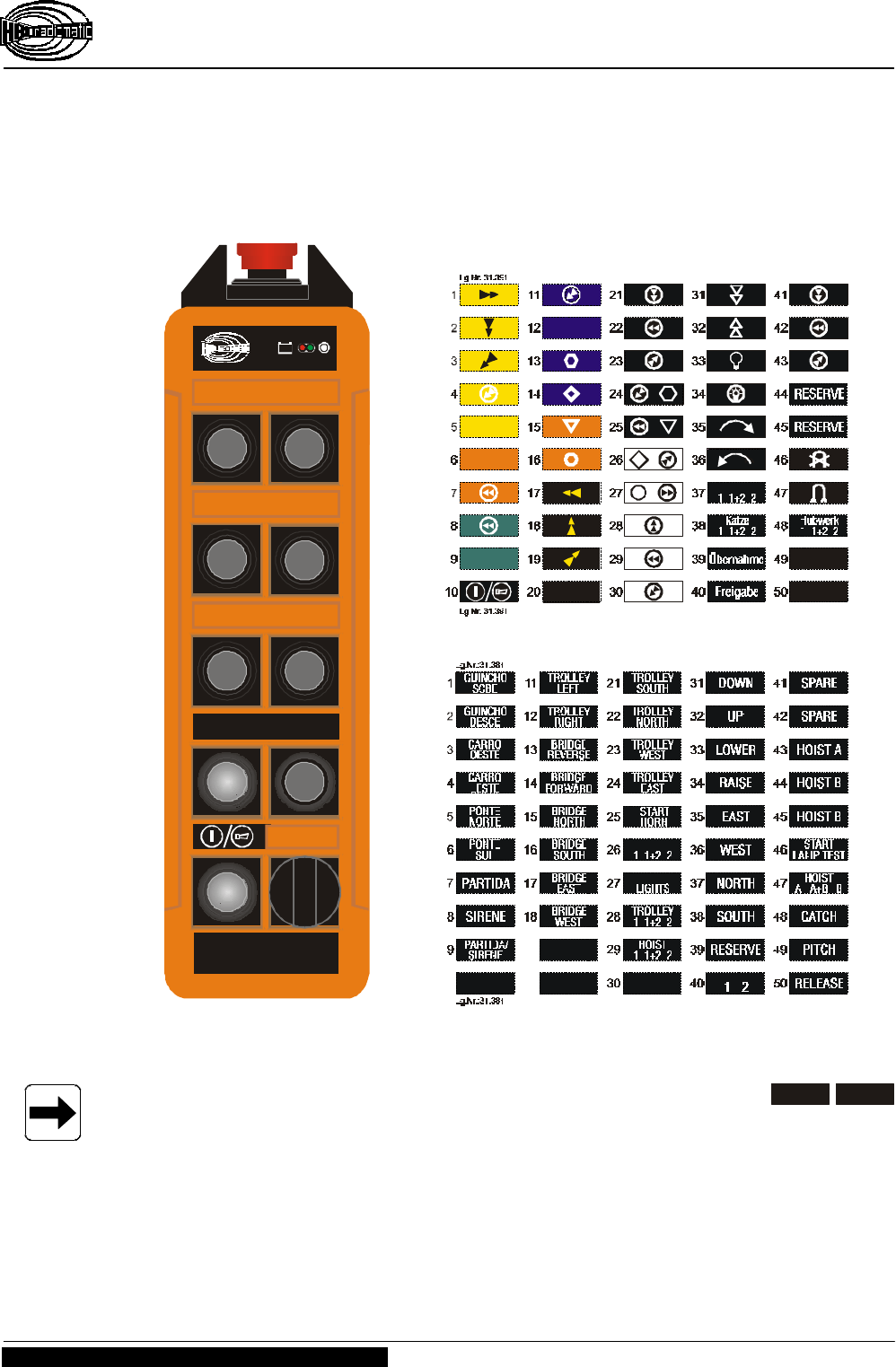
Transmitter Inscription
The transmitter can be labeled by means of the attached sheets.
Please note: The push buttons in the fourth line are solely reserved for START STOP
and may not be used for other commands !
+
_
31.379
31.292
File: MIC5-3_W_O.CDR [ CorelDraw 8.0 ] 13.11.2001
START STOP
micron 3 / 5 ; Sheet 3 ; English or Portuguese Text
micron 3 / 5 ; Sheet 1 ; Standard symbols
Operating Instructions
Radio Transmitter micron 5-3
BE-MICR5-3_V2-1.DOC [ Word 2000 ] US Page 11 / 18
HBC-radiomatic GmbH • D-74564 Crailsheim • GERMANY
Information and specifications subject to change without notice. 02-13-2002
Radio Control System
3.1 Battery and Battery Charger
3.1.1 FuB 3A Transmitter Battery
The age and ambient temperature are decisive for the
length of battery application. Older batteries lose capacity
over time. Temperatures under zero also have a negative
effect on battery charge.
The length of serviceable battery life depends on how the
battery is treated. When handled properly the FuB 3A can
exceed 500 charging cycles. Do not totally discharge or
short-circuit contacts as this can permanently destroy the
battery.
We recommend recharging the battery only when it is empty, i.e. when the red LED
blinks or an acoustic signal sounds. Always store rechargeable batteries at room
temperature (20 °C or 68 °F).
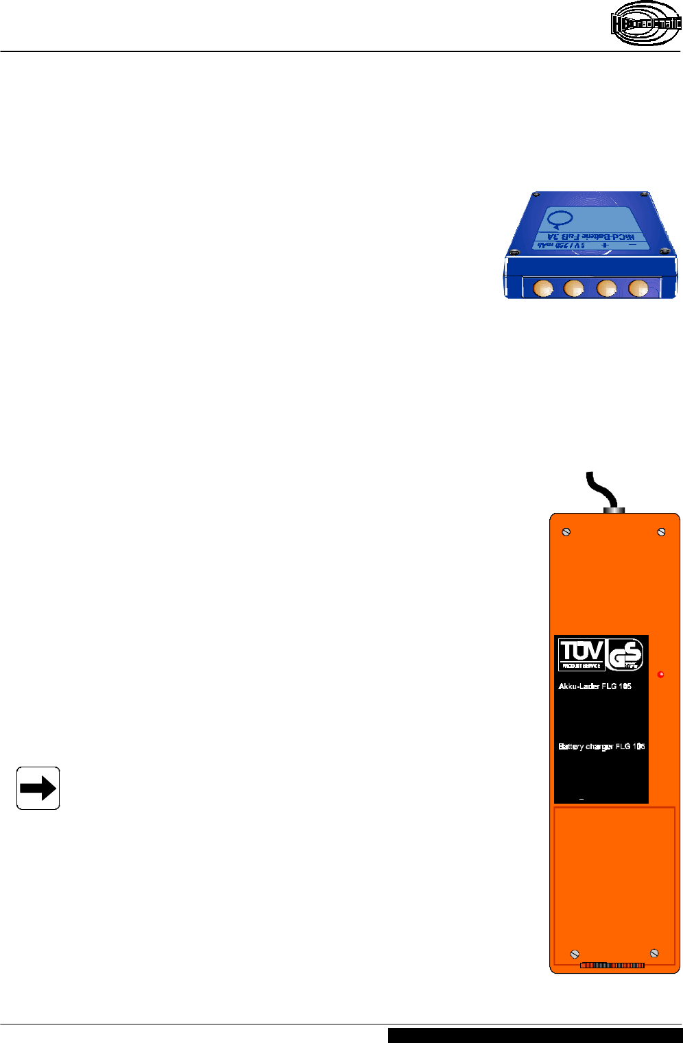
3.1.2 FLG 105 Battery Charger
Recharging batteries
1. Connect battery charger to mains (refer to nameplate on
battery charger for operating voltage).
2. Insert the adapter for the FuB 3A battery in the charging
compartment of the battery charger.
3. Insert battery with the nameplate facing up into the battery
compartment (pos. Á).
Charging indicator (red LED ; pos. ÀÀ )
LED lit :...................................... battery charging.
LED OFF or blinking : ................. battery full, i.e. operable.
LED blinks
when inserting battery : .............. battery totally discharged
or defective.
Note :
– A discharged FuB 3A battery recharges in approx. 2 hours.
Electronics in the battery charger ensure that charging does
not exceed 5 hours.
– The quick charging of NiCd batteries should only take place
at temperatures between +10 °C and +40 °C (50 °F and
104 °F).
– Protect battery contacts against short circuits. Never store
batteries in a tool box or trouser pockets. A bunch of keys
is enough to short the battery. Always use the protective
cap included.
– Use the charger at room temperature (20 °C or 68 °F) and
protect it from extreme heat (direct sun).
++
LadungnurbeiZimmertemperatur!
Akkueinlegen.
Dauerlicht:Akkuwirdgeladen.
Blinken:Akkuentnehmen.
Betriebsanleitung beachten!
For roomtemperatureonly!
Insertbattery.
Steadylight:Charging.
Blinkinglight:Removebattery.
!See operating instructions
Á
À
Operating Instructions
Radio Transmitter micron 5-3
Page 12 / 18 BE-MICR5-3_V2-1.DOC [ Word 2000 ] US
HBC-radiomatic GmbH • D-74564 Crailsheim • GERMANY
02-13-2002 Information and specifications subject to change without notice.
Radio Control System
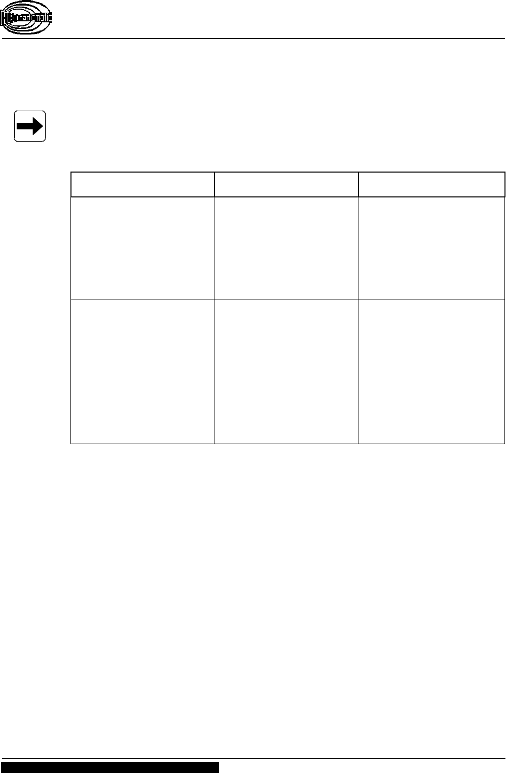
4 Fault Correction
Note :
Check the functions using the cabin or cable controls first !
Problem Possible Cause Remedy
Transmitter does not react
when switched on. − No power. − Check the battery
contacts for damage or
contamination.
− Insert a fully charged
battery in battery
compartment.
− Recharge battery.
Low-power indicator blinks
after minimal operating
time, i.e. red LED
illuminates.
− Battery contacts are
contaminated or
damaged.
− Battery not charged.
− Battery defective.
− Check battery contacts
for damage or
contamination.
− Fully recharge battery.
− Ensure that recharging
process runs correctly.
− Check transmitter
functions using a fully
charged or replacement
battery.
Operating Instructions
Radio Transmitter micron 5-3
BE-MICR5-3_V2-1.DOC [ Word 2000 ] US Page 13 / 18
HBC-radiomatic GmbH • D-74564 Crailsheim • GERMANY
Information and specifications subject to change without notice. 02-13-2002
Radio Control System
5 Maintenance
The radio control system is virtually maintenance-free. However, the following points
should be taken into due consideration :
Ø Ensure that the STOP push button works smoothly.
Contaminants of any kind can reduce or fully block the switch function.
Ø Charge and discharge transmitter batteries regularly.
Ø Never use a high-pressure cleaner or steam jet cleaner to "clean" the transmitter.
Use a soft brush or cloth only!
Note :
Should you have any problems with the radio control system, contact your local
distributor or HBC-radiomatic GmbH.
5.1 In the Event of a Fault
Warning :
Never operate a crane or machine with a faulty or defective radio control system.
Ø Never try to repair the transmitter electronics ! Opening the transmitter housing
terminates the manufacturer guarantee.
– Send any defective or faulty equipment to you local distributor or to the
manufacturer. They are experts and have the necessary know-how and OEM
spare parts.
– Always send transmitter and receiver and enclose a detailed description of the
problem.
– Do not forget to enclose your address and telephone number so that we can get
in touch with you quickly if necessary.
Ø To avoid damage during transport, use the original packing supplied with the
transmitter and receiver, otherwise pack securely. Send the consignment to your
distributor or to the following address :
HBC-radiomatic GmbH
Haller Strasse 49 – 53
D-74564 Crailsheim
Germany
Ø Should you chose to deliver a defective radio control system personally to your
distributor or our factory, please call and arrange an appointment.
HBC-radiomatic GmbH
– Customer Services / Repair Service –
Tel.: +49 ( 0 ) 79 51 – 3 93 - 800
Operating Instructions
Radio Transmitter micron 5-3
Page 14 / 18 BE-MICR5-3_V2-1.DOC [ Word 2000 ] US
HBC-radiomatic GmbH • D-74564 Crailsheim • GERMANY
02-13-2002 Information and specifications subject to change without notice.
Radio Control System
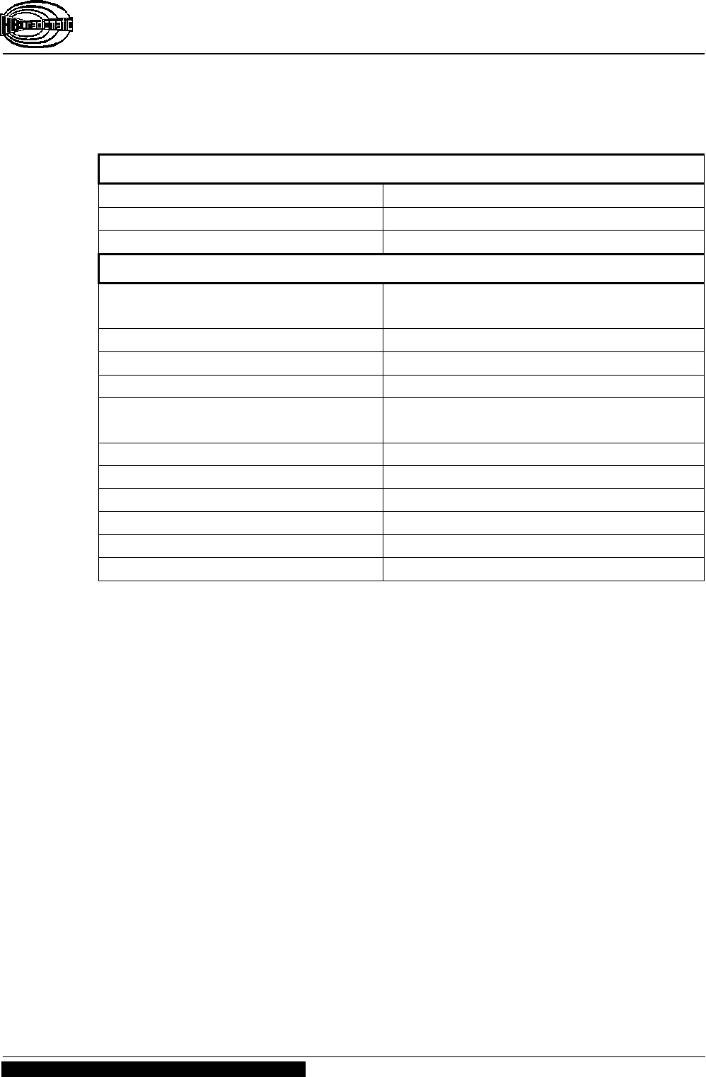
6 Technical Data
General Technical Data
System micron 5-3
Max. number of control commands 14
Unique system addresses over 65,000 combinations
Transmitter-Specific Technical Data
Transmitting power FuS 680/3 :
FuS 671/3 :
< 5 mW ( synthesizer )
< 10 mW ( synthesizer )
Transmitter antenna internal
Battery type FuB 3A ( blue , NiCd )
Power supply with NiCd battery 6 V DC / 250 mAh
Battery charge at 50 % duty cycle :
at 100 % duty cycle :
8 hours
4 hours
Operating temperature range –25 °C to 75 °C ( –13 °F to +167 °F )
Housing material ABS plastic
Housing color orange
Dimensions 255 x 64 x 50 mm ( 9.8 x 2.5 x 2.2 " )
Weight approx. 450 g ( 1.0 lb. )
Protection class IP 55 ( Nema 4 )
Operating Instructions
Radio Transmitter micron 5-3
BE-MICR5-3_V2-1.DOC [ Word 2000 ] US Page 15 / 18
HBC-radiomatic GmbH • D-74564 Crailsheim • GERMANY
Information and specifications subject to change without notice. 02-13-2002
Radio Control System
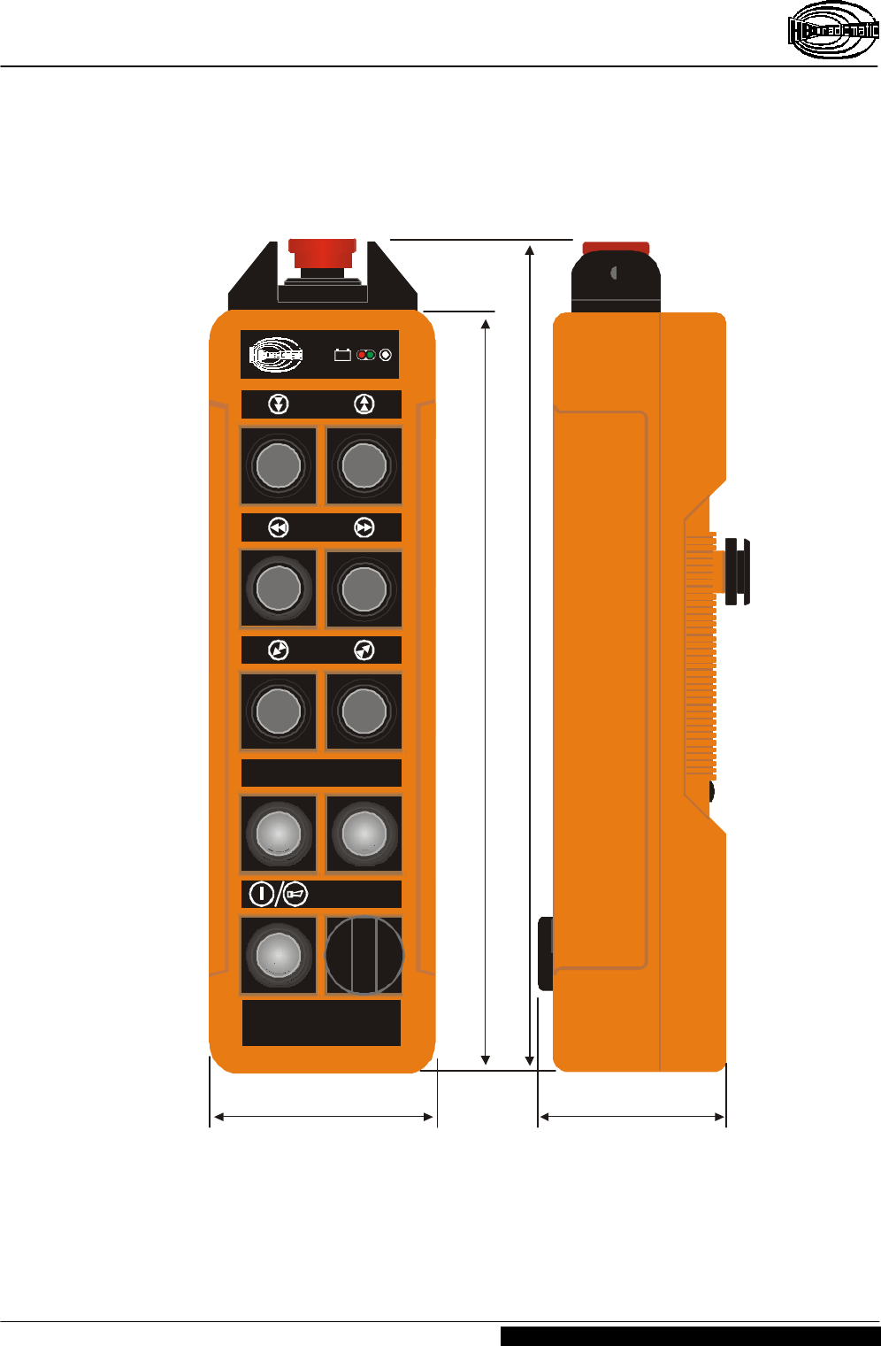
Dimensions
+
_
31.379
31.292
File:
MIC5-3_MASS.CDR [ CorelDraw 8.0 ] 14.11.2001 US
START STOP
56 mm (2.2 ")64 mm (2.5 ")
215 mm (8.5 ")
255 mm (10.0 ")
Operating Instructions
Radio Transmitter micron 5-3
Page 16 / 18 BE-MICR5-3_V2-1.DOC [ Word 2000 ] US
HBC-radiomatic GmbH • D-74564 Crailsheim • GERMANY
02-13-2002 Information and specifications subject to change without notice.
Radio Control System
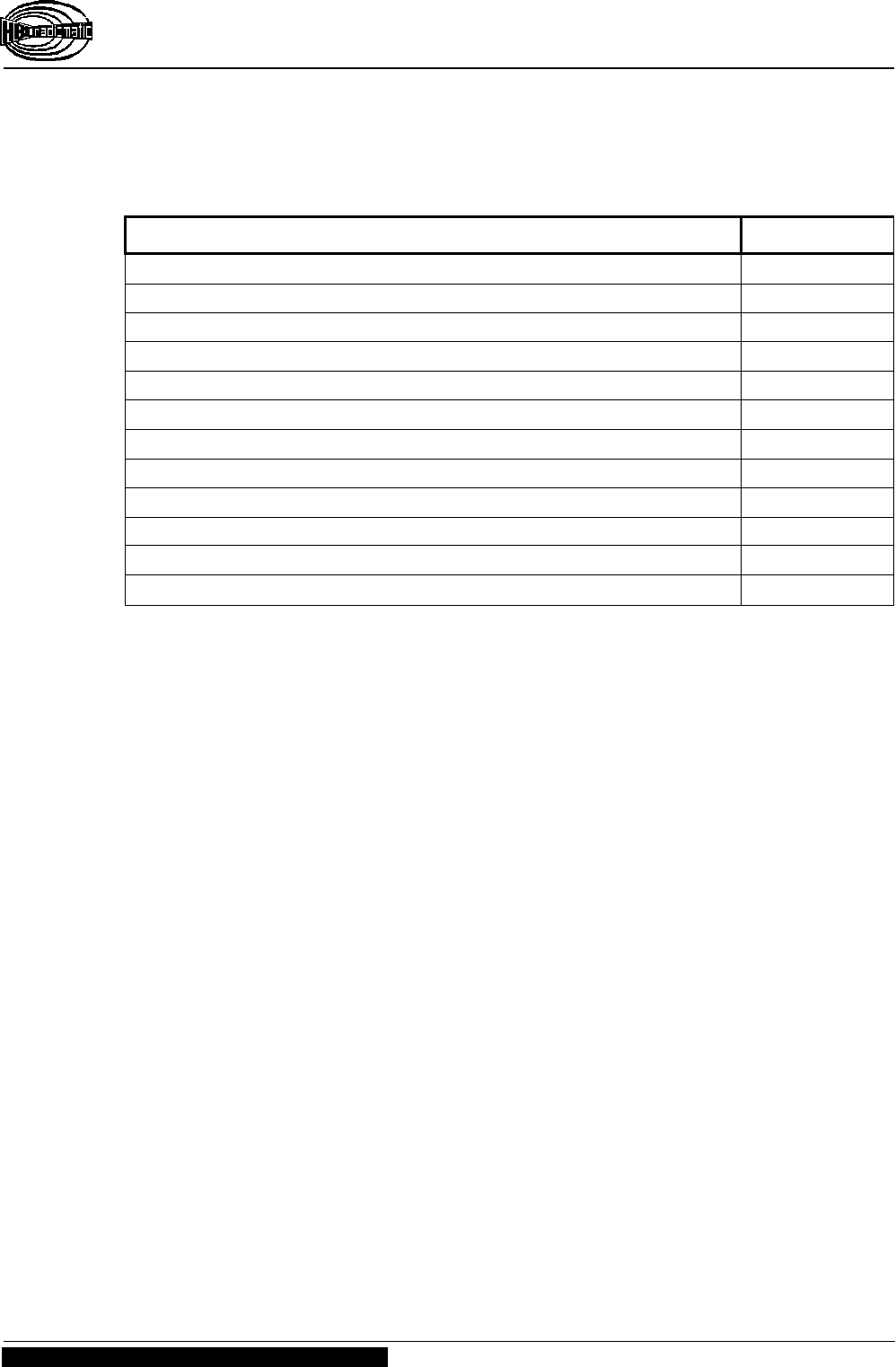
6.1 Accessories
Description Order no.
Belt clip for micron transmitter ( standard accessory ) D-500006
Nylon carrier bag for micron D-500012
Shock protection with wrist strap B-500015
NiCd battery FuB 3A, blue, 6 V / 250 mAh FuB 3A
Adapter for FuB 3A batteries ( inset for battery charger ) D-900064
Battery charger FLG 105 ( indicate distribution voltage range ! ) FLG 105
Transmitter labels micron 3 / 5, sheet 1 [ 31.391 ] G-900208
Transmitter labels micron 3 / 5, sheet 2 [ 31.392 ] G-900209
Transmitter labels micron 3 / 5, sheet 3 [ 31.384 ] G-900210
Transmitter labels micron 3 / 5, sheet 4 [ 31.385 ] G-900211
Self-adhesive foil DIN, colored D-900051
Self-adhesive foil SEB, colored D-900052
Operating Instructions
Radio Transmitter micron 5-3
BE-MICR5-3_V2-1.DOC [ Word 2000 ] US Page 17 / 18
HBC-radiomatic GmbH • D-74564 Crailsheim • GERMANY
Information and specifications subject to change without notice. 02-13-2002
Radio Control System
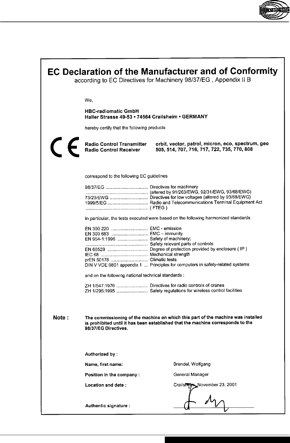
7 Certificates and Approvals

Operating Instructions
Radio Transmitter micron 5-3
Page 18 / 18 BE-MICR5-3_V2-1.DOC [ Word 2000 ] US
HBC-radiomatic GmbH • D-74564 Crailsheim • GERMANY
02-13-2002 Information and specifications subject to change without notice.
Radio Control System