HBC radiomatic MSB004 Radio Transmitter Spectrum 3 M User Manual BE SP3M V2 4 FCC
HBC-radiomatic GmbH Radio Transmitter Spectrum 3 M BE SP3M V2 4 FCC
manual
Operating Instructions
Radio Transmitter spectrum 3 M
BE-SP3M-V2-4(FCC).doc [ Word 2000 ] FL/US/MB Page 1 / 22
HBC-radiomatic GmbH • D-74564 Crailsheim • Germany
Information and specifications subject to change without notice. 2003-02-12
Radio Control System
HBC – Radio Control
R
Ra
ad
di
io
o
T
Tr
ra
an
ns
sm
mi
it
tt
te
er
r
s
sp
pe
ec
ct
tr
ru
um
m
3
3
M
M
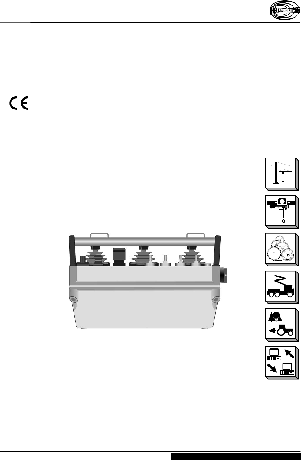
for the Constructional and Industrial Use
FCC ID: NO9MSB004

Operating Instructions
Radio Transmitter spectrum 3 M
Page 2 / 22 BE-SP3M-V2-4(FCC).doc[ Word 2000 ] FL/US/MB
HBC-radiomatic GmbH • D-74564 Crailsheim • Germany
2003-02-12 Information and specifications subject to change without notice.
Radio Control System
Manufacturer : HBC-radiomatic GmbH
Haller Straße 49 - 53
74564 Crailsheim • Germany
Tel. +49 ( 0 ) 79 51 – 3 93 - 0
Fax +49 ( 0 ) 79 51 – 3 93 - 50
E-mail: info@radiomatic.com
http://www.hbc-radiomatic.com
HBC radiomatic GmbH is not liable for any misprints or errors! – All rights reserved.
™ radiomatic is a registered German trademark.
© 2002 – 12 , HBC-radiomatic GmbH , D-74564 Crailsheim
No part of any software or of the present document may be reproduced in any manner whatsoever without
the expressed written permission of HBC-radiomatic GmbH.

Operating Instructions
Radio Transmitter spectrum 3 M
BE-SP3M-V2-4(FCC).doc [ Word 2000 ] FL/US/MB Page 3 / 22
HBC-radiomatic GmbH • D-74564 Crailsheim • Germany
Information and specifications subject to change without notice. 2003-02-12
Radio Control System
Table of Contents
1 Description.................................................................................... 4
2 Safety Instructions ........................................................................ 5
2.1 Pictographs.............................................................................................5
2.2 General Safety Instructions....................................................................6
2.3 Operator Safety Instructions ..................................................................7
3 Operation....................................................................................... 8
Automatic Switch-OFF ( APO Function ) ................................................9
Slewing Gear Release.............................................................................9
3.1 Battery and Battery Charger.................................................................10
3.1.1 FuB 10 AA and FuB 10 XL Transmitter Batteries ....................10
3.1.2 FLG 110 Battery Charger .........................................................11
3.2 Special Operating Modes ( Optional )...................................................12
3.2.1 Option Scanner ( Frequency Selector ) ...................................12
3.2.2 Option "Pitch – Catch".............................................................13
3.2.3 Option Tandem Operation........................................................14
3.2.4 Option infrakey ........................................................................16
3.2.4.1 infrakey Set-up ..........................................................17
4 Fault Correction ...........................................................................18
5 Maintenance .................................................................................19
5.1 In the Event of a Fault...........................................................................19
6 Technical Data..............................................................................20
6.1 Dimensions and Operating Elements ...................................................21
7 Certification and Approvals .........................................................22
Operating Instructions
Radio Transmitter spectrum 3 M
Page 4 / 22 BE-SP3M-V2-4(FCC).doc[ Word 2000 ] FL/US/MB
HBC-radiomatic GmbH • D-74564 Crailsheim • Germany
2003-02-12 Information and specifications subject to change without notice.
Radio Control System
1 Description
The spectrum 3 M transmitter is designed to transmit command instructions for
controlling constructional, industrial and mobile cranes, hoists and machines.
Depending on the type and version selected, up to 64 digital + 8 proportional control
commands plus the integrated STOP commands are available to the operator.
A non-interchangeable system address ensures the functional safety of the radio control
system when operating cranes or machines. This feature is particularly important when
several cranes or machines are in use, for example in halls and shops. The system
address is exclusively allocated to each HBC radio transmitter and its respective
receiver.
It is not possible to activate crane or machine functions using a radio control
system allocated to another crane or machine.
The radio control system consists of the spectrum 3 transmitter, two rechargeable NiCd
batteries, a memory effect-free battery charger and a receiver with antenna.
The transmitter housing with integrated antenna is made of glass-fiber reinforced plastic.
State of the art radio technology complying with the latest guidelines of the regulations
on labor safety and the use of highly developed microprocessor technology guarantees
optimal operating safety, availability and longevity.
The transmitter has general telecommunications approvals. It is not necessary to have
or to apply for a license to operate the transmitter with the respective receiver. The
transmitter must be operated in the 433.100 MHz to 434.750 MHz range or 869 MHz to
870 MHz bandwidth. The transmitter is equipped with < 10 mW (average) transmitting
power.
Operating the radio transmitter using a different frequency range or transmitting power
requires the approval of the competent regulative authorities for telecommunication.
Note :
Changes or modifications not expressly approved by the party responsible for compliance could
void the user´s authority to operate the equipment.
Operating Instructions
Radio Transmitter spectrum 3 M
BE-SP3M-V2-4(FCC).doc [ Word 2000 ] FL/US/MB Page 5 / 22
HBC-radiomatic GmbH • D-74564 Crailsheim • Germany
Information and specifications subject to change without notice. 2003-02-12
Radio Control System
2 Safety Instructions
2.1 Pictographs
The following pictographs will be used throughout the present operating instructions :
Indicates a possible shock hazard
Contacting components under voltage may lead to death. Housing marked with this
symbol may only be opened by qualified electricians after having disconnected the
device from the mains supply (supply voltage, operating voltage or input terminal
voltage).
Indicates safety relevant passages
You will find this pictograph as an indicator for occupational safety measures. The
neglecting of such measures poses a serious hazard.
Always observe the instructions and be particularly attentive and careful.
Avoid any situations that could at any time be a danger to persons or machines.
Indicates important information
This symbol brings your attention to important information on how to secure a long
serviceable life of the radio control system.
Pay attention to the comments and instructions given. Ignoring the information provided
may permanently impair the reliability and operability of the equipment.

Operating Instructions
Radio Transmitter spectrum 3 M
Page 6 / 22 BE-SP3M-V2-3.DOC [ Word 2000 ] FL/US
HBC-radiomatic GmbH • D-74564 Crailsheim • Germany
2002-12-03 Information and specifications subject to change without notice.
Radio Control System
2.2 General Safety Instructions
Radio controls facilitate and increase the operating efficiency of cranes and machines.
Nevertheless, the operator must thoroughly understand and be in a position to properly
use a radio control system !
Read the Operating Instructions Manual carefully and thoroughly before working with
the transmitter for the first time !
The operator undertakes to strictly adhere to the instructions and proceedings
described in this manual, as well as to follow the general rules and regulations for
worker safety and accident prevention. Ignoring any such instructions or regulations
could pose a fatal threat to the operator or others.
Keep this manual on location and readily available at all times !
Only authorized and properly trained personnel may operate the transmitter.
Anyone who is under the influence of drugs, alcohol or medication that has a
detrimental effect on a person's reactions may at no time commission, operate,
maintain or repair the transmitter.
Before switching the transmitter on ensure that no-one is or can be endangered by
the initiated operation.
With the first signs of any malfunction related to the operative safety and reliability
of the device the operator must immediately shut down or not activate the
transmitter. For the purpose of the present manual "shut down" implies :
– switching OFF the transmitter,
– storing the transmitter in a safe place and ensuring no unauthorized access,
– de-energizing the receiver,
– unplugging the connection cable on the receiver !
Defects must be repaired and sources of interference must be removed
immediately !
A defective transmitter may only be repaired by qualified and competent personnel.
Use only original spare parts of HBC-radiomatic GmbH. The use of any other spares
will render the technical inspectorate approval invalid as well as substantially
impede operative safety.
Observe all periodical tests and inspections that are required by law or
recommended in the present operating instructions !
When using the transmitter always observe the regulations and instructions
stipulated in the authoritative worker safety and accident prevention regulations.
– The transmitter has been manufactured in accordance with the regulations and
guidelines stipulated in the German Trade Association's "Safety and Accident
Prevention Regulations for Operating Cranes by Radio Controls" (VBG 9; ZH
1/547) and pr EN 12077-1.
– The transmitter has been tested and approved in accordance with EMC
guidelines and complies with the authoritative standards for emitted interference
and interference immunity.
Use the transmitter cautiously and properly. In particular when using a transmitter to
radio control a machine or crane for the first time.
Operating Instructions
Radio Transmitter spectrum 3 M
BE-SP3M-V2-4(FCC).doc [ Word 2000 ] FL/US/MB Page 7 / 22
HBC-radiomatic GmbH • D-74564 Crailsheim • Germany
Information and specifications subject to change without notice. 2003-02-12
Radio Control System
2.3 Operator Safety Instructions
Before beginning crane operation, position yourself so that you have a clear and
complete overview of the working radius of the crane or machine.
To operate, hold the transmitter securely in your hand. Use the optional wrist strap.
Follow these instructions to ensure personal safety.
Depending on your angle or position to the crane or machine, the transmitter control
commands “trolley left” and “trolley right” appear to interchange ! It is essential that
you take your bearings to the crane or machine into due consideration before
operating equipment.
In case of an emergency or any disturbances within the working range of the crane
or machine, switch the transmitter off immediately by pressing the STOP
pushbutton. Should the transmitter show signs of technical failure or breakdown,
disconnect the radio control system immediately !
Switch the transmitter off during breaks and after finishing work to avoid any
misoperation of crane or machine by unintended activation of the operator controls.
– These precautions are particularly important whenever changing your position or
climbing over an obstacle.
Never leave an activated transmitter unattended. The operator undertakes to follow
and comply with the authoritative regulations for worker safety and accident
prevention.
Note :
– In the event of an interruption of the radio link during a working cycle – what can
occasionally happen – both transmitter and receiver automatically shut down (so-
called "compulsory switch-off").
To reactivate the system release all operator controls, such as pushbuttons or
momentary contacts, and allow the control elements to return to their zero position.
Press the "ON " pushbutton. The system must be reactivated before the crane or
machine can react to control commands! This feature hinders any uncontrolled or
unwanted crane or machine movement, should the radio link be interrupted.
– When operating a crane by means of a radio control system for the first time, you
may miss the physical contact to the crane that you were used to in the operating
stand. As you are no longer in the crane and can no longer sense the starting of the
crane movements as distinctly, crane reactions will appear sluggish or dull.
Operating Instructions
Radio Transmitter spectrum 3 M
Page 8 / 22 BE-SP3M-V2-3.DOC [ Word 2000 ] FL/US
HBC-radiomatic GmbH • D-74564 Crailsheim • Germany
2002-12-03 Information and specifications subject to change without notice.
Radio Control System
3 Operation
Caution :
The operation of the transmitter is permissible only with the carrying set included with
the transmitter (possibility of mixing up the operator controls) !
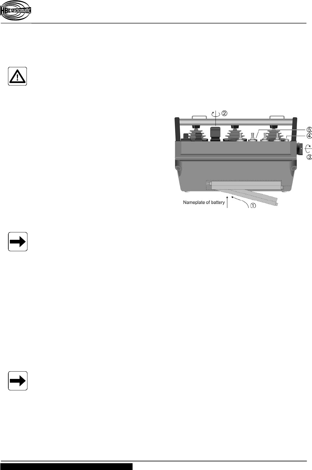
1. Before commissioning the transmitter
or initial operation, insert a fully
charged battery (FuB 15 AA, yellow
or FuB 10 XL, light blue) into battery
compartment (pos. ) at the bottom
of the transmitter. The battery
supplies the necessary working
voltage (6 V DC).
2. Turn STOP pushbutton (pos. ) to
unlock.
3. Turn key switch (pos. ) to the right
(position "1" = ON).
4. Switch ON transmitter and crane or
machine with "ON" pushbutton.
The green LED (pos. ) flashes, i.e.
the transmitter is operable.
Important Information :
After switching ON the transmitter and before operating the crane or machine you must
always :
– trigger the acoustic signal by pressing the "Horn" pushbutton. This warns all
colleagues that the crane or machine is about to move;
– test the operativeness of the STOP pushbutton.
A radio connection to the receiver is established when the red LED "HF/RF/H.F./HF" on
the receiver will be extinguished and the green LED "Si1" is illuminated (see radio status
panel of the receiver), i.e. the radio system is ready to operate and the control
commands may be input via the transmitter.
If the red LED on the transmitter (fig. above, pos. ) flashes and / or an acoustic signal
comes, this indicates that the battery is almost fully discharged. Now, you must replace
the discharged battery by a charged one and recharge the discharged battery (refer to
chapter "Battery and Battery Charger").
Note :
If the discharged battery is not replaced by a charged one, the transmitter will be
automatically switched OFF after a few minutes.
Operating Instructions
Radio Transmitter spectrum 3 M
BE-SP3M-V2-4(FCC).doc [ Word 2000 ] FL/US/MB Page 9 / 22
HBC-radiomatic GmbH • D-74564 Crailsheim • Germany
Information and specifications subject to change without notice. 2003-02-12
Radio Control System
Should the operator switch off the transmitter with the STOP pushbutton, following steps
have to be carried out for further radio transmission :
1. Switch off the transmitter via the key switch.
2. Unlock the STOP pushbutton by turning.
3. Switch the transmitter on again via the key switch.
4. Press the “(Crane) On” button.
Note :
Use the key switch to switch the transmitter on and off. Use the STOP pushbutton only
in case of an emergency or any disturbances within the working range
Automatic Switch-OFF ( APO Function )
For safety reasons we have equipped the transmitter with an automatic switch-OFF
(APO = Automatic Power Off function). The transmitter is automatically put out of circuit
after 15 minutes of non-use.
The automatic switch-OFF also saves battery power.
Note :
The automatic switch-OFF (APO function) does not relieve the operator of his
responsibility to turn OFF the transmitter when not in use !
The transmitter can be reactivated by means of the "ON“ pushbutton.
Slewing Gear Release
Note :
This function is available only by radio control systems for construction cranes.
Whenever the command "slewing gear release" is actuated by means of the radio
control, it is important that the respective check be made.
Due to the above, a clearly visible indicator lamp should be installed on the crane –
possibly a flashing one.
Operating Instructions
Radio Transmitter spectrum 3 M
Page 10 / 22 BE-SP3M-V2-3.DOC [ Word 2000 ] FL/US
HBC-radiomatic GmbH • D-74564 Crailsheim • Germany
2002-12-03 Information and specifications subject to change without notice.
Radio Control System
3.1 Battery and Battery Charger
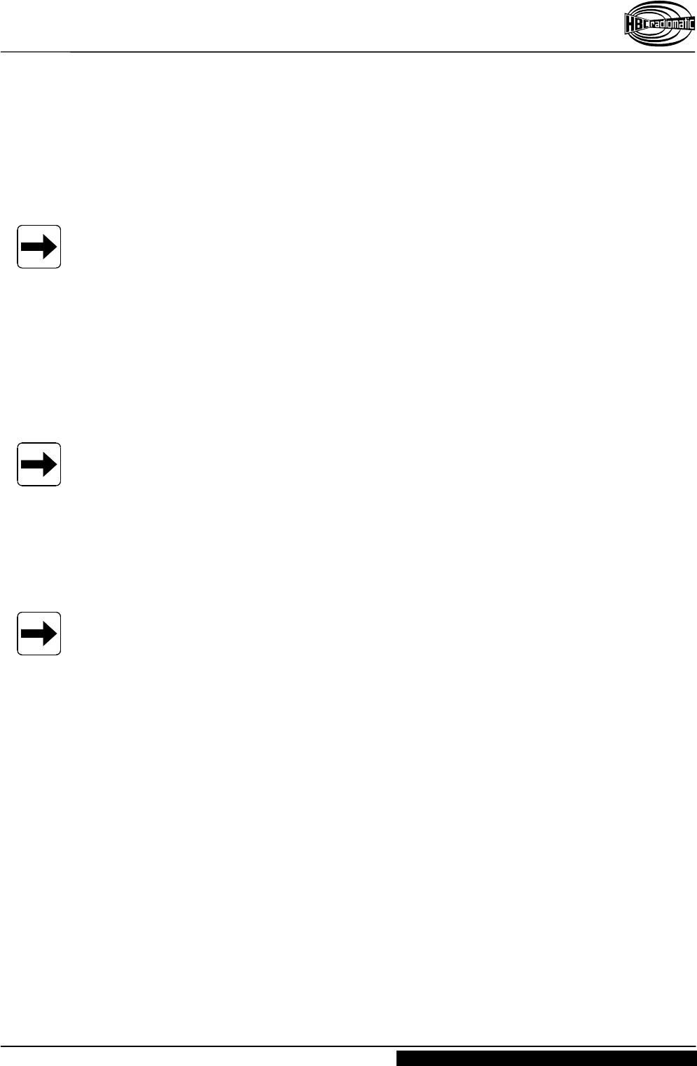
3.1.1 FuB 10 AA and FuB 10 XL Transmitter Batteries
The length of the battery charge depends on the age of the battery and the ambient
temperature.
Older batteries lose capacity over time. Temperatures under 32 °F (0 °C) have a
negative effect on battery charge.
When handled properly battery can exceed 500 charging cycles.
Recharge the battery only when it is empty, i.e. when the red display on the
transmitter blinks and / or the acoustic signal sounds.
Always store rechargeable batteries at room temperature.
Never store batteries in a tool box or in pants pockets.
Protect battery contacts against short circuits. Always use the protective cap
included.
We recommend to recharge batteries that have not been used for a certain time, before
putting them into operation.
Operating Instructions
Radio Transmitter spectrum 3 M
BE-SP3M-V2-4(FCC).doc [ Word 2000 ] FL/US/MB Page 11 / 22
HBC-radiomatic GmbH • D-74564 Crailsheim • Germany
Information and specifications subject to change without notice. 2003-02-12
Radio Control System
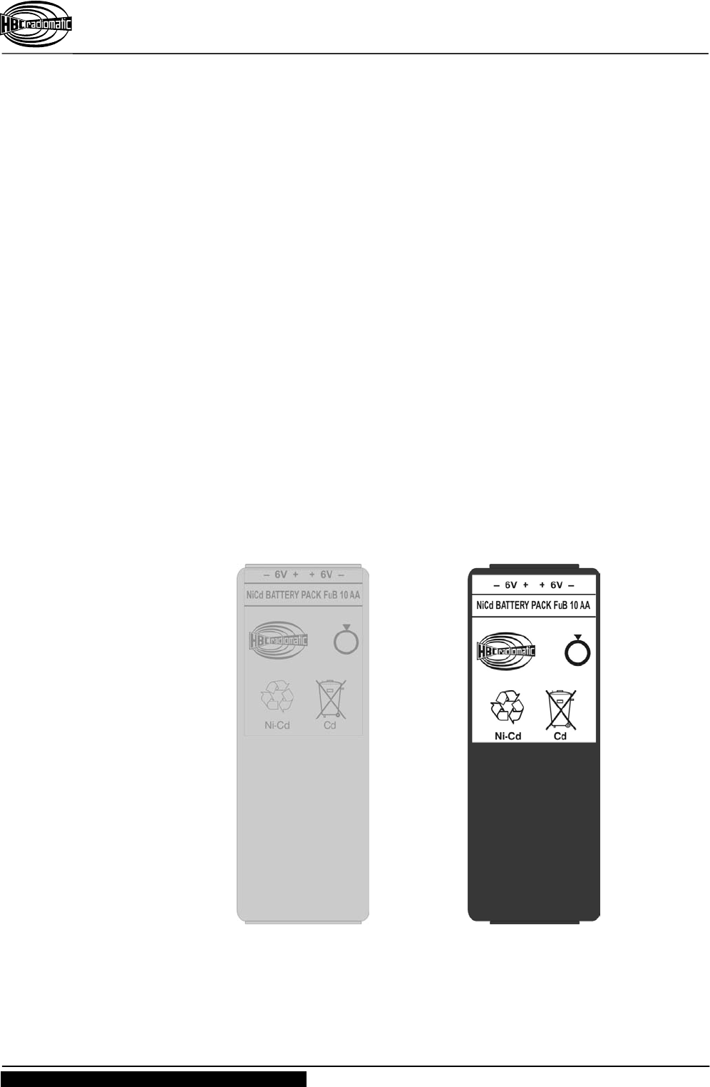
3.1.2 FLG 110 Battery Charger
With the battery charger FLG 110 the batteries FuB 10 AA and FuB 10 XL can be
charged.
Operation:
1. Connect the battery charger to mains (refer to
nameplate of the battery charger for operating
voltage).
2. Insert the battery with the nameplate facing up
into the charging compartment ➁.
Charging indicator (LED ; pos. ➀)
LED lights green :............ battery is charging.
LED blinks green : .......... battery is charged,
i.e. ready for operation.
LED lights red :................ battery is deep
discharged or defective.
A discharged battery recharges in approx. 3 hours.
Electronics in the battery charger avoid over-
charging of the battery.
Note :
The quick charging of NiCd batteries should only take place at temperatures
between +10 °C and +40 °C (50 °F and 104 °F).
Use the charger at room temperature (20 °C or 68 °F) and protect it from extreme
heat (direct sun).
Do not cover the battery charger, e. g. with rags, paper and similar objects, while
charger is in use !
When installing the battery charger into a vehicle it must be connected via the
ignition switch, i.e. charging is prevented when the ignition key is in the off position.
Operating Instructions
Radio Transmitter spectrum 3 M
Page 12 / 22 BE-SP3M-V2-3.DOC [ Word 2000 ] FL/US
HBC-radiomatic GmbH • D-74564 Crailsheim • Germany
2002-12-03 Information and specifications subject to change without notice.
Radio Control System
3.2 Special Operating Modes ( Optional )
Note :
This chapter describes special operating modes that are not available with all crane
systems.
If your radio control system is not equipped with the features described, you may ignore
the following and continue with the next chapter.
3.2.1 Option Scanner ( Frequency Selector )
Note :
This is a standard function by radio control systems for construction cranes, and
available as an option by radio control systems for industrial cranes.
The transmitter and receiver are equipped with a "Scanner" (frequency selector)
operating mode with 4 radio frequencies (refer to wiring diagrams).
In the event that the momentarily used radio channel is being used by another operator,
the transmitter can be switched over to a different channel by means of the rotary
switch. The receiver scanner automatically adjusts the receiver to the selected radio
frequency.
After turning ON the transmitter (set key switch to "ON" position and do not forget to
unlock STOP pushbutton), the receiver automatically resets the system to the new
frequency selected in less than a second.
Operating Instructions
Radio Transmitter spectrum 3 M
BE-SP3M-V2-4(FCC).doc [ Word 2000 ] FL/US/MB Page 13 / 22
HBC-radiomatic GmbH • D-74564 Crailsheim • Germany
Information and specifications subject to change without notice. 2003-02-12
Radio Control System
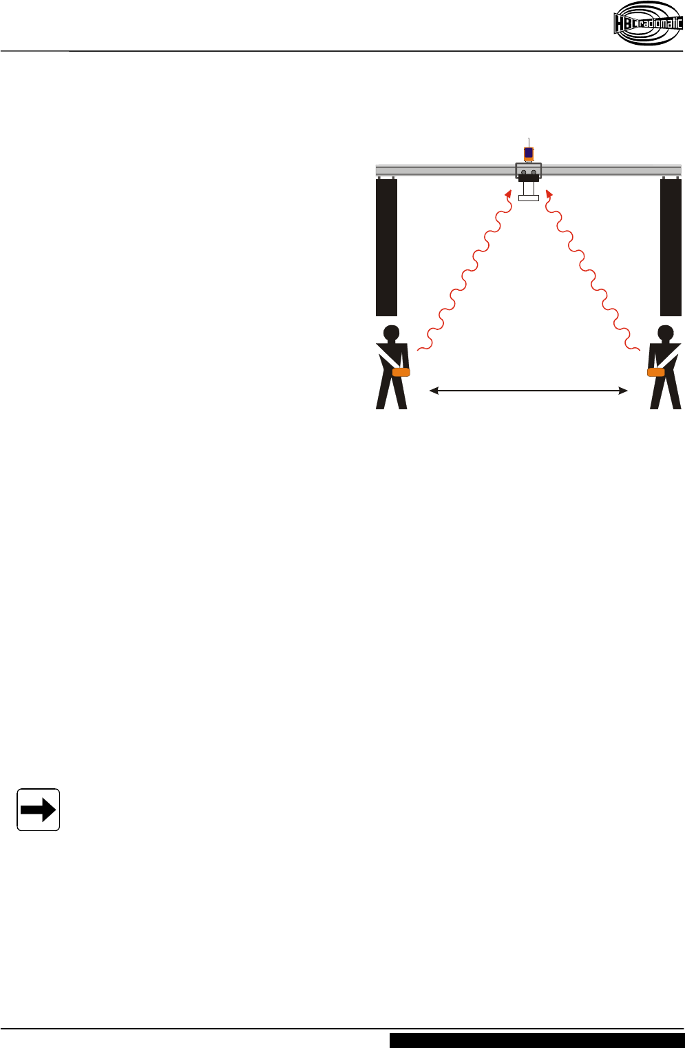
3.2.2 Option "Pitch – Catch"
The "Pitch – Catch" operating mode
allows two or more crane operators
equipped with one transmitter each to
independently use the same crane
The crane is equipped with a radio
receiver that can receive and monitor
transmitter frequencies.
After activating the receiver all
transmitters have equal access to the
control system.
Releasing the crane ( "Pitch" )
To release the crane :
1. Enter the "pitch" command via the
rotary switch or pushbutton on
transmitter 1 or transmitter 2.
2. For safety reasons we recommend switching OFF transmitter 1 or transmitter 2. This
will avoid operator errors.
This cancels the access rights of transmitter 1 or transmitter 2 to the crane.
Taking over control of the crane ( "Catch" )
To take over the control of the crane, enter the "catch" command via the rotary switch or
pushbutton on transmitter 1 or transmitter 2.
The transmitter with control over the crane retains the access to the receiver
(transmitter 1 or transmitter 2) until the operator has issued the "Pitch" statement.
Operating Example :
Transmitter 2 has control over the crane control system. Transmitter 1 is to be given
control. The operators must continue as follows :
1. Enter the "pitch" command via the rotary switch or pushbutton on transmitter 2.
2. For safety reasons we recommend switching OFF transmitter 2, i.e. turn the key
switch to the "0 = OFF" position.
3. Activate transmitter 1, i.e. turn the key switch to the "1 = ON" position.
4. Enter the "catch" command via the rotary switch or pushbutton on transmitter 1.
Transmitter 1 now has sole access to all crane functions.
Notes :
– A power loss at the receiver-end activates a general reset of the crane system. All
transmitters have access to the crane radio controls. This implies that the pitch –
catch settings must be readjusted at the transmitter-end.
– Should an operator forget to issue the "pitch" statement and shuts down his
transmitter (transmitter shut down using the STOP pushbutton or technical failure)
the second transmitter has no access to the crane radio control system. In order to
give transmitter 2 access to the radio control system the receiver must be cut OFF
from the supply voltage (master switch) and the crane control system reactivated as
described above.
– The "pitch" and "catch" commands should therefore be laid on a rotary switch or a
pushbutton. In addition, a lamp that can be mounted on the crane will indicate when
the receiver is busy (busy display).
"Catch" and "Release"
Crane receiver with
2 reception frequencies
File:
C_R-SP.CDR [CorelDraw 8.0] 2000-11-07 FL
Transmitter 1 Transmitter 2
Operating Instructions
Radio Transmitter spectrum 3 M
Page 14 / 22 BE-SP3M-V2-3.DOC [ Word 2000 ] FL/US
HBC-radiomatic GmbH • D-74564 Crailsheim • Germany
2002-12-03 Information and specifications subject to change without notice.
Radio Control System
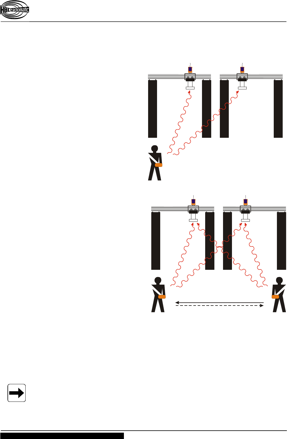
3.2.3 Option Tandem Operation
Tandem Operation T1
Parallel control of two cranes
(2 receivers) on one radio frequency
is possible with one radio transmitter
using the option tandem operation
"T1".
The individual cranes can be
controlled using the rotary switch on
the transmitter (fig. right, bottom).
The individual switching positions
mean :
A Access to crane A
A+B Access to both cranes
B Access to crane B
Tandem Operation T2
Operation of two cranes is possible
with two complete radio control
systems (2 transmitters, 2 receivers)
using the option tandem operation
"T2", whereby each transmitter is a
"master" transmitter.
The radio transmitter key for crane A
can also be used to switch over the
transmitter for crane A to crane B. To
do this, the following steps must be
carried out :
1. Remove the key from master
transmitter 2. This switches OFF
master transmitter 2.
2. Put the key from master
transmitter 2 into master
transmitter 1.
This activates the release for crane pre-selection in the transmitter.
or
3. Remove the key from master transmitter 1. This switches OFF master transmitter 1.
4. Put the key from master transmitter 1 into master transmitter 2.
This activates the release for crane pre-selection in the transmitter.
5. Select the corresponding crane by means of the rotary switch on the master
transmitter 1 or master transmitter 2 : either crane A or crane A+B (both cranes) or
crane B.
The corresponding cranes are now running in the pre-selected operation mode.
Note :
During tandem operation "T2", each transmitter is a "master" transmitter.
It is possible, however, to operate only one "master" and one "slave" transmitter. In this
case, only the "master" transmitter is able to control both cranes in tandem operation.
Crane B / receiver 2
with 1 reception frequency,
address 2
Crane A / receiver 1
with 1 reception frequency,
address 1
File:
TANDEM_T1_SP.CDR [ CorelDraw 8.0 ] 2000-11-06 FL
Transmitter 1
Transmitter key 2
Crane B / receiver 2
with scanner and
2 reception frequencies,
address 2
Crane A / receiver 1
with scanner and
2 reception frequencies,
address 1
File:
TANDEM_T2_SP.CDR [ CorelDraw 8.0 ] 2000-11-06 FL
Master transmitter 1 Master transmitter 2
Operating Instructions
Radio Transmitter spectrum 3 M
BE-SP3M-V2-4(FCC).doc [ Word 2000 ] FL/US/MB Page 15 / 22
HBC-radiomatic GmbH • D-74564 Crailsheim • Germany
Information and specifications subject to change without notice. 2003-02-12
Radio Control System
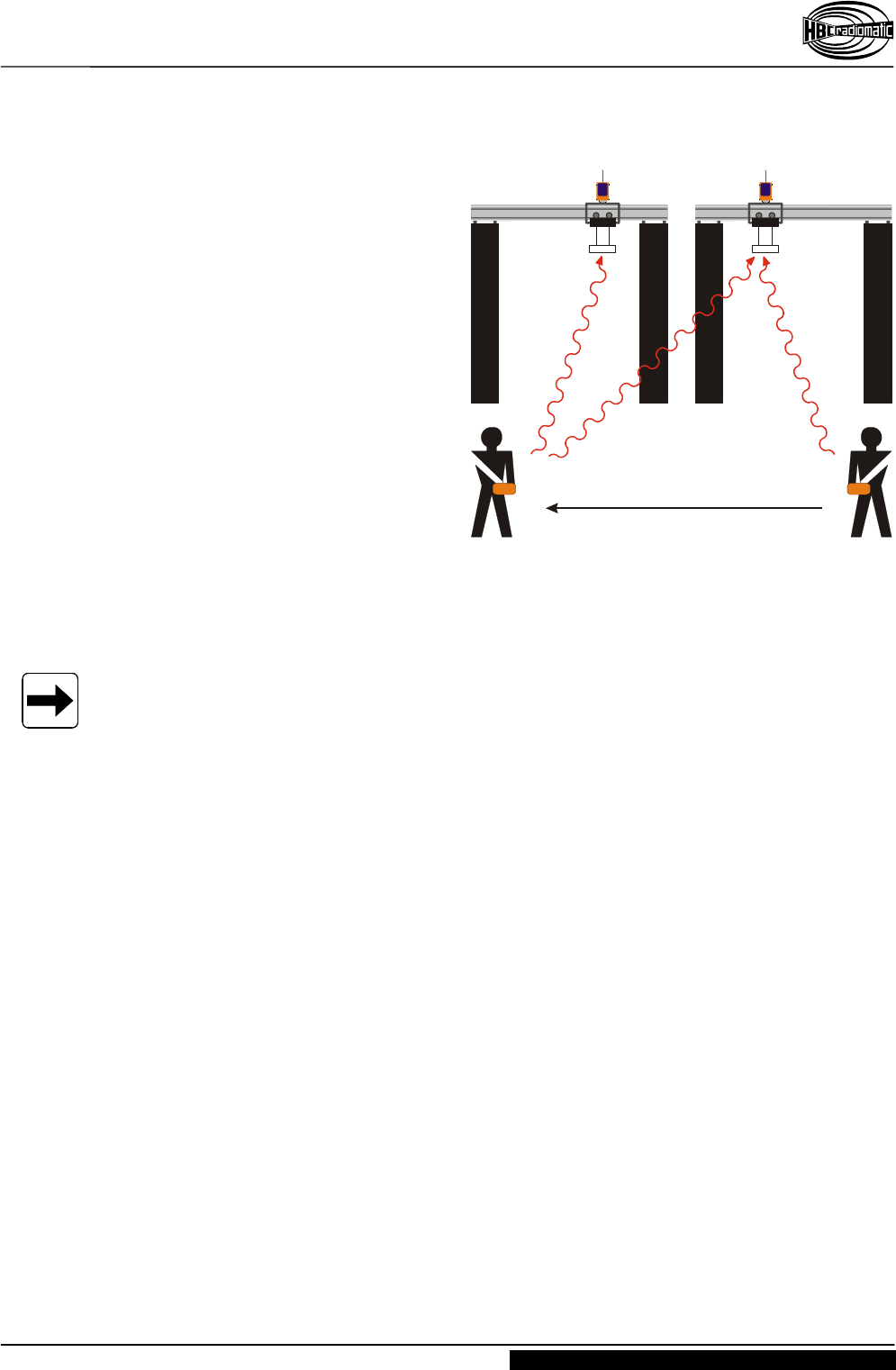
Tandem Operation TM / TS
Operation of two cranes is possible
with two complete radio controls
(2 transmitters, 2 receivers) using the
option tandem operation "TM / TS",
whereby one transmitter is a "master"
and the other transmitter is a "slave".
The radio transmitter key for crane B
can also be used to switch over the
transmitter for crane A to crane B.
To do this, the following steps must
be carried out :
1. Remove the key from the slave
transmitter. This switches OFF
the slave transmitter.
2. Put the key from slave transmitter
into master transmitter.
This activates the release for crane pre-selection in the transmitter.
3. Select the corresponding crane by means of the rotary switch on the master
transmitter : either crane A or crane A+B (both cranes) or crane B.
The corresponding cranes are now running in the pre-selected operation mode.
Note :
To ensure safe operation during tandem operation "T2" and "TM / TS", it is imperatively
required that only one key is available to the respective crane operators.
The extra key supplied with transmitter 2 must therefore be deposited at a superior,
authoritative position and only be handed out in clarified cases.
Transmitter key 2
Crane B / receiver 2 with
2 reception frequencies,
address 2
Crane A / receiver 1
with 1 reception frequency,
address 1
File:
TANDEM_TM_SP.CDR [ CorelDraw 8.0 ] 2000-11-06 FL
Master transmitter Slave transmitter
Operating Instructions
Radio Transmitter spectrum 3 M
Page 16 / 22 BE-SP3M-V2-3.DOC [ Word 2000 ] FL/US
HBC-radiomatic GmbH • D-74564 Crailsheim • Germany
2002-12-03 Information and specifications subject to change without notice.
Radio Control System
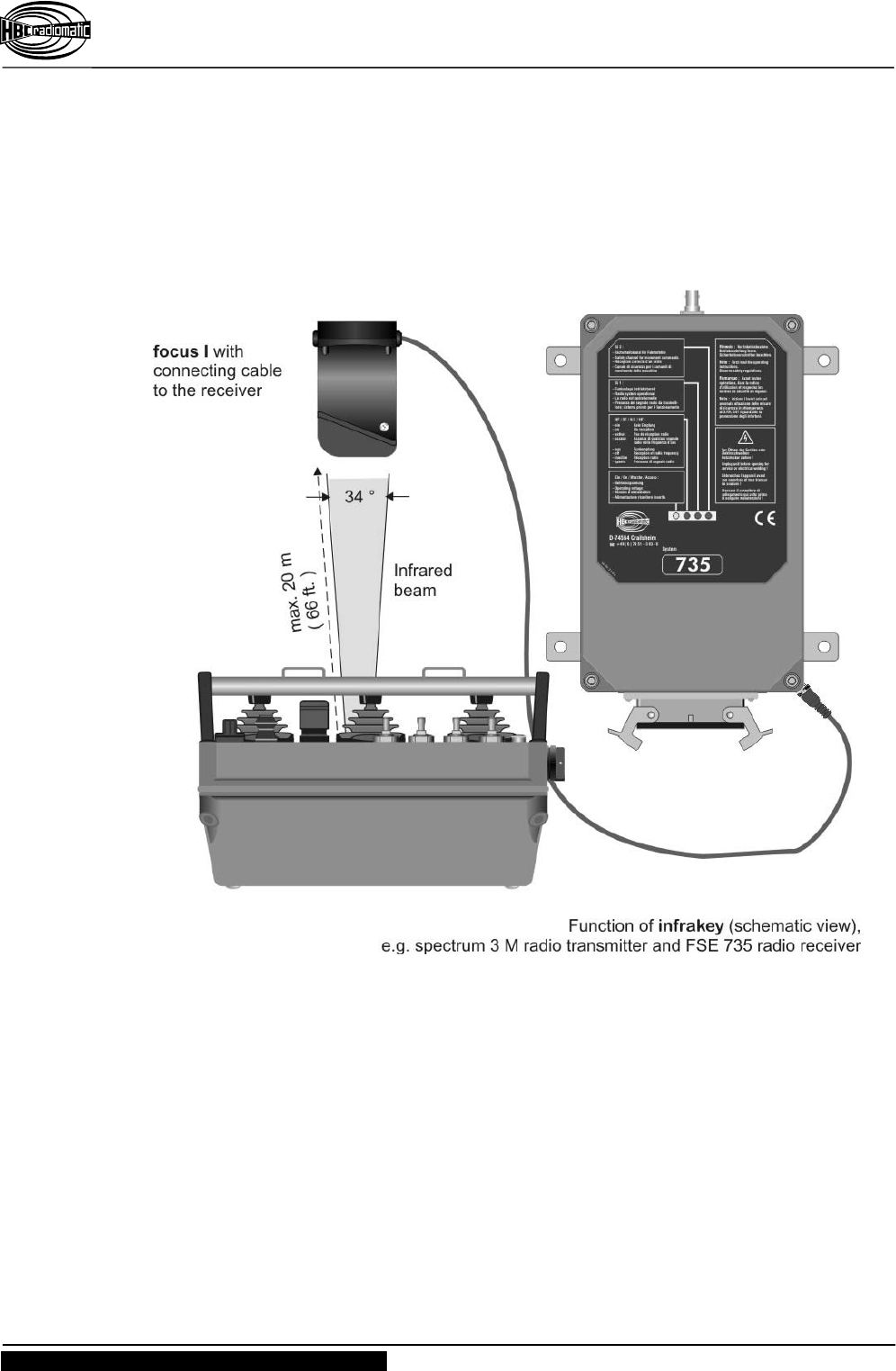
3.2.4 Option infrakey
infrakey is an additional infrared module for the transmitter and the receiver.
Due to separate crane activation via infrared link it increases the safety of operation, i.e.
the crane can not become inadvertently enabled.
The range of the infrared beam is max. approx. 20 meters (66 feet) and the angle of
radiation is 34°.
To activate infrakey, press the "(Crane) On" pushbutton on the transmitter.
Operating Instructions
Radio Transmitter spectrum 3 M
BE-SP3M-V2-4(FCC).doc [ Word 2000 ] FL/US/MB Page 17 / 22
HBC-radiomatic GmbH • D-74564 Crailsheim • Germany
Information and specifications subject to change without notice. 2003-02-12
Radio Control System
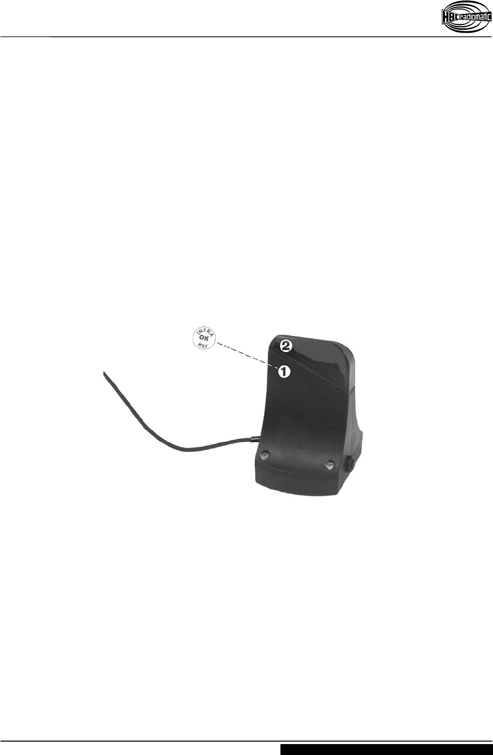
3.2.4.1 infrakey Set-up
Please follow these steps when replacing a focus I infrakey receiver, or up-grading an
existing radio system with focus I:
1. Connect the focus I infrakey receiver to the radio receiver.
2. Insert a charged battery into the battery compartment of the transmitter.
3. Release the STOP-pushbutton on the transmitter (if locked) and turn on the
transmitter using the key switch.
4. Press the set-up pushbutton on the focus I infrakey receiver until the LED
blinks. Release the button.
5. Press the "(Crane) On" pushbutton on the transmitter until the LED on the focus I
infrakey receiver blinks rapidly. Release the pushbutton and the LED will go off.
6. Affix the "INFRAKEY OK" sticker above the set-up pushbutton .
The focus I infrakey receiver can now recognize the transmitter's exclusive security
telegram.

Operating Instructions
Radio Transmitter spectrum 3 M
Page 18 / 22 BE-SP3M-V2-3.DOC [ Word 2000 ] FL/US
HBC-radiomatic GmbH • D-74564 Crailsheim • Germany
2002-12-03 Information and specifications subject to change without notice.
Radio Control System
4 Fault Correction
Note :
Please check the functions using the cabin or cable controls first !
Problem Possible Cause Remedy
The transmitter does not
react when switched on.
− There is no power. − Check the battery
contacts for damage or
contamination.
− Insert a fully charged
battery in battery
compartment.
− Recharge battery.
Low-power indicator blinks
after minimal operating
time, i.e. the red transmitter
LED illuminates.
− The battery contacts are
contaminated or
damaged.
− The battery not charged.
− The battery defective.
− Check the battery
contacts for damage or
contamination.
− Fully recharge the
battery.
− Ensure that the
recharging process runs
correctly.
− Check the transmitter
functions using a fully
charged or replacement
battery.
Operating Instructions
Radio Transmitter spectrum 3 M
BE-SP3M-V2-4(FCC).doc [ Word 2000 ] FL/US/MB Page 19 / 22
HBC-radiomatic GmbH • D-74564 Crailsheim • Germany
Information and specifications subject to change without notice. 2003-02-12
Radio Control System
5 Maintenance
The radio control system is virtually maintenance-free. The following points, however,
should be taken into consideration :
Ensure that the STOP pushbutton works smoothly.
Mortar residue and contaminants of any kind can reduce or fully block the switch
function.
Inspect the rubber bellows of the compact joysticks regularly for leak-tightness.
Replace immediately if cracks appear since the penetration of dirt and humidity may
damage the function of the compact joysticks.
Charge and discharge transmitter batteries regularly.
Never use a high-pressure cleaner or steam jet cleaner to "clean" the transmitter.
Use a soft brush or cloth only !
Note :
Should you have any problems with the radio control system, contact your local
distributor or HBC-radiomatic GmbH.
5.1 In the Event of a Fault
Warning :
Never operate a crane or machine with a faulty or defective radio control system !
Never try to repair the transmitter electronics ! Opening the transmitter housing
terminates the manufacturer guarantee.
– Send any defective or faulty equipment to you local distributor or to the
manufacturer. They are experts and have the necessary know-how and OEM
spare parts.
– Always send both transmitter and receiver and enclose a detailed description of
the problem.
– Do not forget to enclose your address and telephone number so that we can get
in touch with you quickly if necessary.
To avoid damage during transport, use the original packing supplied with the
transmitter and receiver, otherwise pack securely. Send the consignment to your
distributor or to the following address :
HBC-radiomatic GmbH
Haller Strasse 49 – 53
D-74564 Crailsheim
Germany
Should you chose to deliver a defective radio control system personally to your
distributor or our factory, please call and arrange an appointment.
HBC-radiomatic GmbH
– Customer Services / Repair Service –
Tel.: +49 ( 0 ) 79 51 – 3 93 - 800

Operating Instructions
Radio Transmitter spectrum 3 M
Page 20 / 22 BE-SP3M-V2-3.DOC [ Word 2000 ] FL/US
HBC-radiomatic GmbH • D-74564 Crailsheim • Germany
2002-12-03 Information and specifications subject to change without notice.
Radio Control System
6 Technical Data
General Technical Data
System spectrum 3 M
Max. number of control commands 64 digital + 8 prop. + STOP
Unique system address over 65.000 combinations
Transmitter Specific Technical Data
Transmitting power with
FuS 671/3 or FuS 680/3 < 10 mW ( synthesizer )
Transmitter antenna internal
Battery type standard :
optional :
FuB 10 AA ( yellow )
FuB 10 XL (blue )
Power supply with NiCd battery 6 V DC / 1200 mAh ( FuB 10 AA )
6 V DC / 1800 mAh ( FuB 10 XL )
Battery charge at 100 % duty cycle : 24 hours
Operating temperature range –25 °C ... +75 °C ( –13 °F ... +167 °F )
Housing material impact resistant plastic
Housing color orange
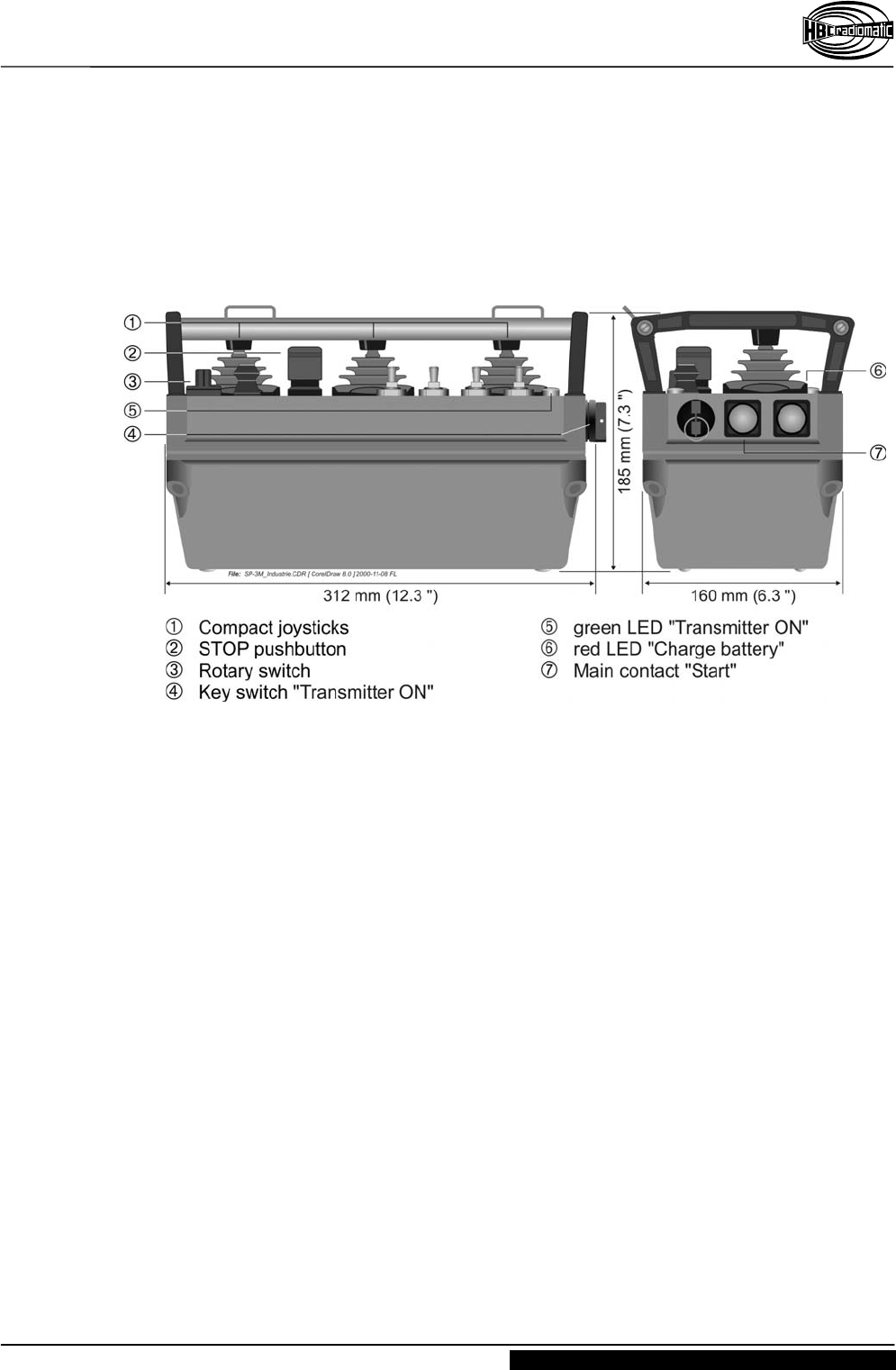
Housing dimensions 312 x 160 x 185 mm ( 12.3 x 6.3 x 7.3 " )
Weight approx. 3,0 kg ( 6.6 lb. )
Protection class IP 55 ( Nema 4 )
Operating Instructions
Radio Transmitter spectrum 3 M
BE-SP3M-V2-4(FCC).doc [ Word 2000 ] FL/US/MB Page 21 / 22
HBC-radiomatic GmbH • D-74564 Crailsheim • Germany
Information and specifications subject to change without notice. 2003-02-12
Radio Control System
6.1 Dimensions and Operating Elements
Operating Instructions
Radio Transmitter spectrum 3 M
Page 22 / 22 BE-SP3M-V2-3.DOC [ Word 2000 ] FL/US
HBC-radiomatic GmbH • D-74564 Crailsheim • Germany
2002-12-03 Information and specifications subject to change without notice.
Radio Control System
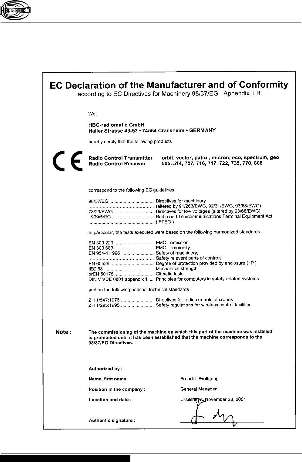
7 Certification and Approvals