HBC radiomatic TC690 Transceiver Module User Manual UM TU690 V1 0
HBC-radiomatic GmbH Transceiver Module UM TU690 V1 0
Users Manual
User Manual
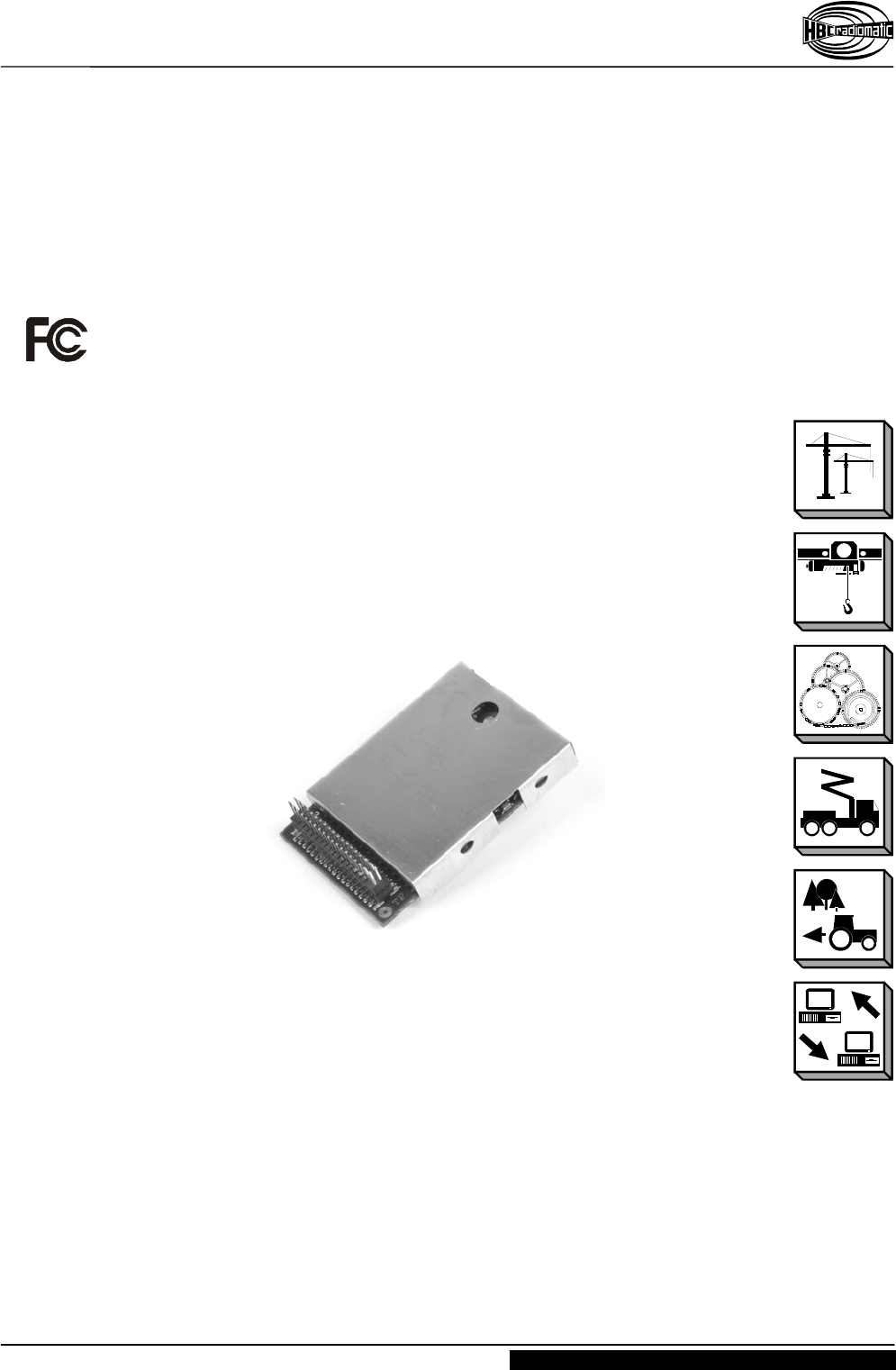
Transceiver Module TC690
UM-TC690-V1-0.DOC [ Word 2000 ] seus/dous Page 1 / 6
HBC-radiomatic GmbH • 74564 Crailsheim • Germany
Information and specifications subject to change without notice. 2004-04-19
www.hbc-radiomatic.com
HBC – Transceiver Module
T
TC
C
6
69
90
0

User Manual
Transceiver Module TC690
Page 2 / 6 UM-TC690-V1-0.DOC [ Word 2000 ] seus/dous
HBC-radiomatic GmbH • 74564 Crailsheim • Germany
2004-04-19 Information and specifications subject to change without notice.
www.hbc-radiomatic.com
Manufactured by: HBC-radiomatic GmbH
Haller Strasse 47 – 53
74564 Crailsheim, Germany
Telephone: +49 ( 0 ) 79 51 – 3 93 – 0
Fax: +49 ( 0 ) 79 51 – 3 93 – 50
E-mail: info@radiomatic.com
http://www.hbc-radiomatic.com
HBC-radiomatic GmbH is not liable for any misprints or errors! – All rights reserved.
™ HBC-radiomatic is a registered German trademark.
© 2004 – 04 , HBC-radiomatic GmbH , 74564 Crailsheim , Germany
No part of any software or of the present document may be reproduced in any manner whatsoever without the expressed
written permission of HBC-radiomatic GmbH.

User Manual
Transceiver Module TC690
UM-TC690-V1-0.DOC [ Word 2000 ] seus/dous Page 3 / 6
HBC-radiomatic GmbH • 74564 Crailsheim • Germany
Information and specifications subject to change without notice. 2004-04-19
www.hbc-radiomatic.com
Table of Contents
Warnings......................................................................................... 4
Operation description TC690.......................................................... 5
Technical data................................................................................. 6
Appendix:
Block diagram

User Manual
Transceiver Module TC690
Page 4 / 6 UM-TC690-V1-0.DOC [ Word 2000 ] seus/dous
HBC-radiomatic GmbH • 74564 Crailsheim • Germany
2004-04-19 Information and specifications subject to change without notice.
www.hbc-radiomatic.com
Warnings
This device complies with part 15 of the FCC rules. Operation is subject to the following
two conditions: (1) This device may not cause harmful interference and (2) this device
must accept any interference received, including interference that may cause undesired
operation.
Caution: Any changes or modifications by the user could void the user’s authority to
operate the equipment!
NOTE: This equipment has been tested and found to comply with the limits for a Class B
digital device, pursuant to part 15 of the FCC Rules. These limits are designed to
provide reasonable protection against harmful interference in a residential installation.
This equipment generates, uses and can radiate frequency energy and, if not installed in
accordance with the instructions, may cause harmful interference to radio
communications. However, there is no guarantee that interference will not occur in a
particular installation. If this equipment does cause harmful interference to radio or
television reception, which can be determined by turning the equipment off and on, the
user is encouraged to try to correct the interference by one or more of the following
measures:
• Reorient or relocate the receiving antenna.
• Increase the separation between the equipment and receiver.
• Connect the equipment into an outlet on a circuit different from that to which the
receiver is connected.
• Consult the dealer or an experienced radio/TV technician for help.

User Manual
Transceiver Module TC690
UM-TC690-V1-0.DOC [ Word 2000 ] seus/dous Page 5 / 6
HBC-radiomatic GmbH • 74564 Crailsheim • Germany
Information and specifications subject to change without notice. 2004-04-19
www.hbc-radiomatic.com
Operation Description TC690
The TC690 consists of an integrated transceiver, voltage regulator, undervoltage reset
circuit and microcontroller. The receiver part is a single conversion superhet. The local
oscillator is a dds type with pll multiplier (see block diagram).
The module is supplied via pins 1~4 (+3.3~4.7V) and pins 11, 12, 27 & 28 (ground). For
correct operation, pin 15 has to be connected to pin 16. Also, pin 23 has to be connected
to pin 24. The module will be switched on by driving pin 9 (DTR) to low level.
The voltage of the SPI interface may not exceed 3.3V! The logic level shall be in the
range 2.3~3.0V for a logical ’1’ and 0~0.7V for a logical ’0’.
When user data is applied to the SPI interface (pins5~8), the data will be transmitted
automatically. When correct data is received, it will be sent through SPI interface.
Frequency programming will be done by applying configuration data to the SPI interface.
In all cases, the microcontroller software checks for correct data format. It is not possible
to transmit outside the programmed frequency range. Since the RF data rate is
independent of the SPI data rate, it is not possible to overmodulate the transmitter. Also,
the transmitting time is limited by software.
User Manual
Transceiver Module TC690
Page 6 / 6 UM-TC690-V1-0.DOC [ Word 2000 ] seus/dous
HBC-radiomatic GmbH • 74564 Crailsheim • Germany
2004-04-19 Information and specifications subject to change without notice.
www.hbc-radiomatic.com
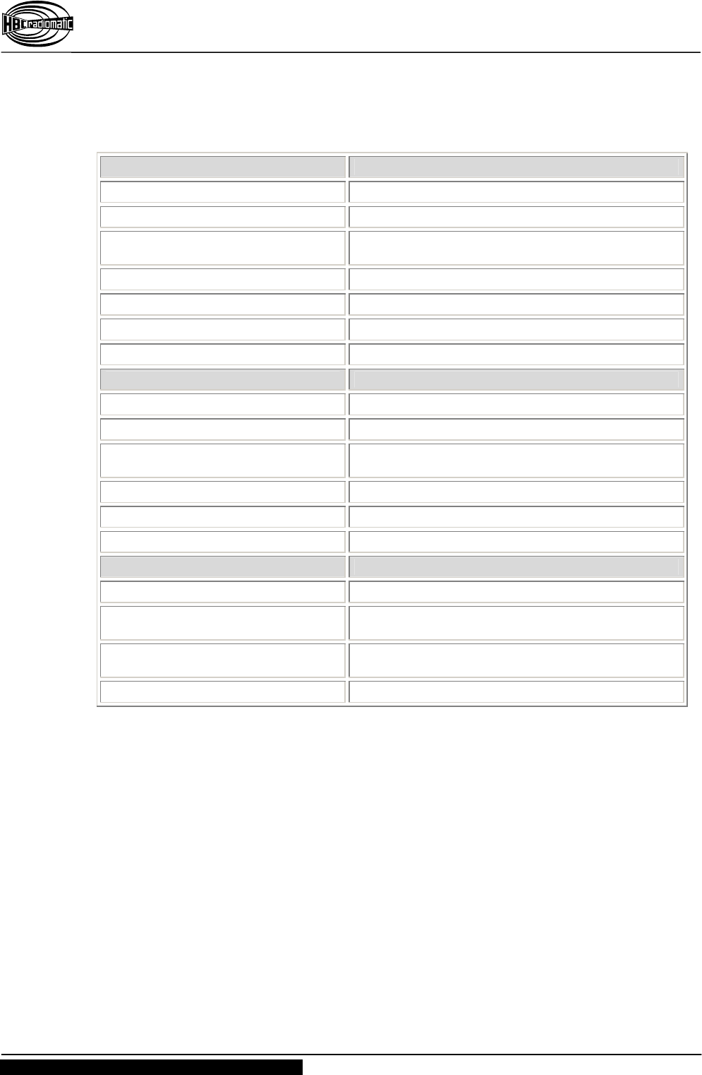
Technical Data
Common parameters
Supply voltage +3.3~+4.7VDC
Temperature range -25~+70°C
Frequency range 902.125~917.875MHz TC690L
912.125~927.875MHz TC690H
Frequency accuracy ±10kHz
RF data rate 15000bps
Frequency deviation 40~50kHz
Channel separation 250kHz
Receive parameters
Supply current 35~45mA
Sensitivity <-95dBm @BER=10-2
Spurious emissions <-60dBm below 1000MHz (conducted)
<-45dBm above 1000MHz (conducted)
Blocking desensitization >80dBc
Co-channel rejection >-10dB
Adjacent channel rejection >60dB
Transmit parameters
Supply current 90~110mA
Output power +13dBm peak, -6dBm average (conducted)
+3dBm peak, -16dBm average (radiated)
Spurious emissions <-54dBm below 1000MHz (conducted)
<-30dBm above 1000MHz (conducted)
Adjacent channel power -36dBm (conducted)