HBC radiomatic TC691 Tranceiver Module User Manual UM TC691 V2
HBC-radiomatic GmbH Tranceiver Module UM TC691 V2
User Manual
User Manual
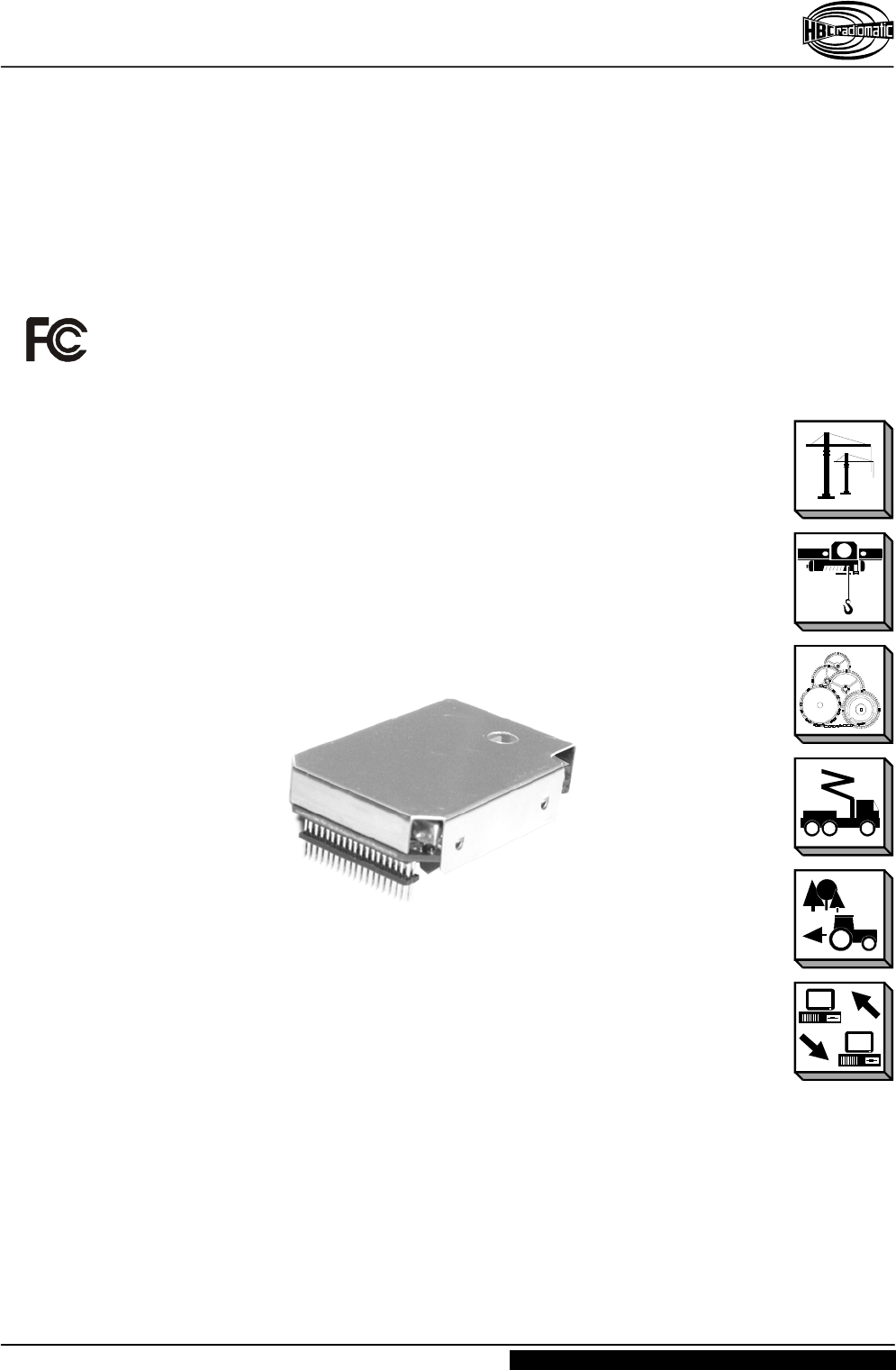
Transceiver Module TC691
UM-TC691-V2.DOC [ Word 2002 ] SEDH/DOKUS Page 1 / 5
HBC-radiomatic GmbH • 74564 Crailsheim • Germany
Information and specifications subject to change without notice. 2006-06-22
www.hbc-radiomatic.com
HBC – Transceiver Module
T
TC
C
6
69
91
1

User Manual
Transceiver Module TC691
UM-TC691-V2.DOC [ Word 2002 ] SEDH/DOKUS Page 2 / 5
HBC-radiomatic GmbH • 74564 Crailsheim • Germany
Information and specifications subject to change without notice. 2006-06-22
www.hbc-radiomatic.com
Manufactured by: HBC-radiomatic GmbH
Haller Strasse 47 – 53
74564 Crailsheim, Germany
Tel: +49 79 51 3 93–0
Fax: +49 79 51 3 93–50
E-mail: info@radiomatic.com
http://www.hbc-radiomatic.com
HBC-radiomatic GmbH is not liable for any misprints or errors! – All rights reserved.
™ HBC-radiomatic is a registered German trademark.
© 2006 – 06 , HBC-radiomatic GmbH , 74564 Crailsheim , Germany
No part of any software or of the present document may be reproduced in any manner whatsoever without the expressed
written permission of HBC-radiomatic GmbH.

User Manual
Transceiver Module TC691
UM-TC691-V2.DOC [ Word 2002 ] SEDH/DOKUS Page 3 / 5
HBC-radiomatic GmbH • 74564 Crailsheim • Germany
Information and specifications subject to change without notice. 2006-06-22
www.hbc-radiomatic.com
Table of Contents
Warnings ........................................................ 4
Technical Data................................................ 5

User Manual
Transceiver Module TC691
UM-TC691-V2.DOC [ Word 2002 ] SEDH/DOKUS Page 4 / 5
HBC-radiomatic GmbH • 74564 Crailsheim • Germany
Information and specifications subject to change without notice. 2006-06-22
www.hbc-radiomatic.com
Warnings
This device complies with part 15 of the FCC rules and with RSS-210 of Industry
Canada. Operation is subject to the following two conditions: (1) This device may not
cause harmful interference and (2) this device must accept any interference received,
including interference that may cause undesired operation.
Caution: Any changes or modifications by the user could void the user’s authority to
operate the equipment!
NOTE: This equipment has been tested and found to comply with the limits for a Class B
digital device, pursuant to part 15 of the FCC Rules. These limits are designed to
provide reasonable protection against harmful interference in a residential installation.
This equipment generates, uses and can radiate frequency energy and, if not installed
and used in accordance with the instructions, may cause harmful interference to radio
communications. However, there is no guarantee that interference will not occur in a
particular installation. If this equipment does cause harmful interference to radio or
television reception, which can be determined by turning the equipment off and on, the
user is encouraged to try to correct the interference by one or more of the following
measures:
• Reorient or relocate the receiving antenna.
• Increase the separation between the equipment and receiver.
• Connect the equipment into an outlet on a circuit different from that to which the
receiver is connected.
• Consult the dealer or an experienced radio/TV technician for help.

User Manual
Transceiver Module TC691
UM-TC691-V2.DOC [ Word 2002 ] SEDH/DOKUS Page 5 / 5
HBC-radiomatic GmbH • 74564 Crailsheim • Germany
Information and specifications subject to change without notice. 2006-06-22
www.hbc-radiomatic.com
Technical Data
Common data (RX+TX):
Frequency range: 902.025 ... 927.975 MHz
Operating voltage: + 3.3 ... 4.6 V
Channel pattern: 25 kHz
LF transmission bandwidth: 150 Hz .... 4.8 kHz
Modulation type: F9D
Operating temperature range: -30 ... +70 °C
Transmitter:
Maximum field strength: 50 mV/m @ 3 m
Frequency deviation: +/- 5 kHz
Current consumption when transmitting: 100 mA
Switch-over time (RX-TX): < 1 ms
Receiver:
Sensitivity: -105 dBm (20dB S/N)
First IF: 45 MHz
Second IF: 455 kHz
Current consumption when receiving: 70 mA
Switch-over time (TX-RX): < 1 ms
LF output voltage: 120 mV RMS at +/-5 kHz deviation (internal test point only!)
IP3: 0 dBm