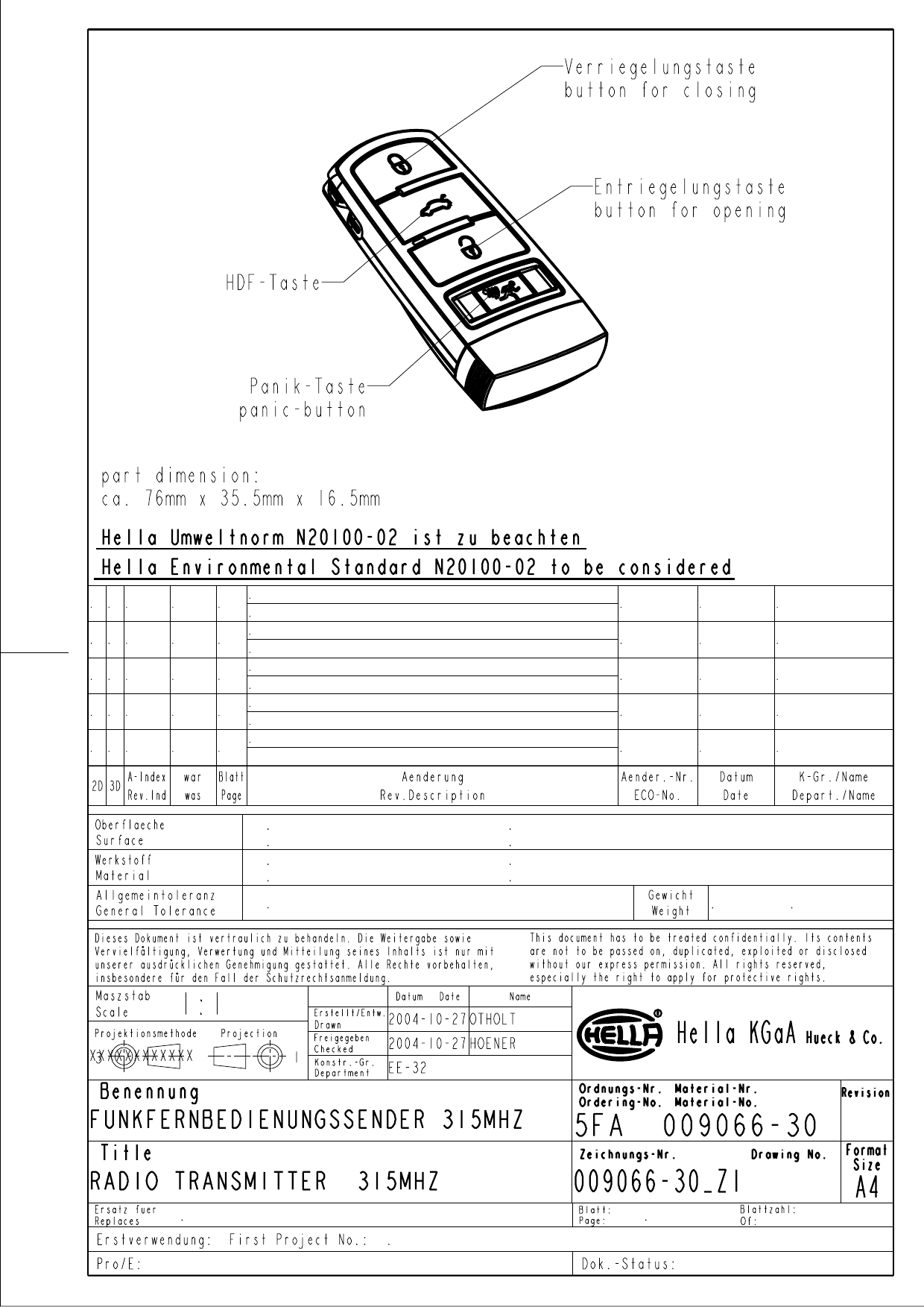
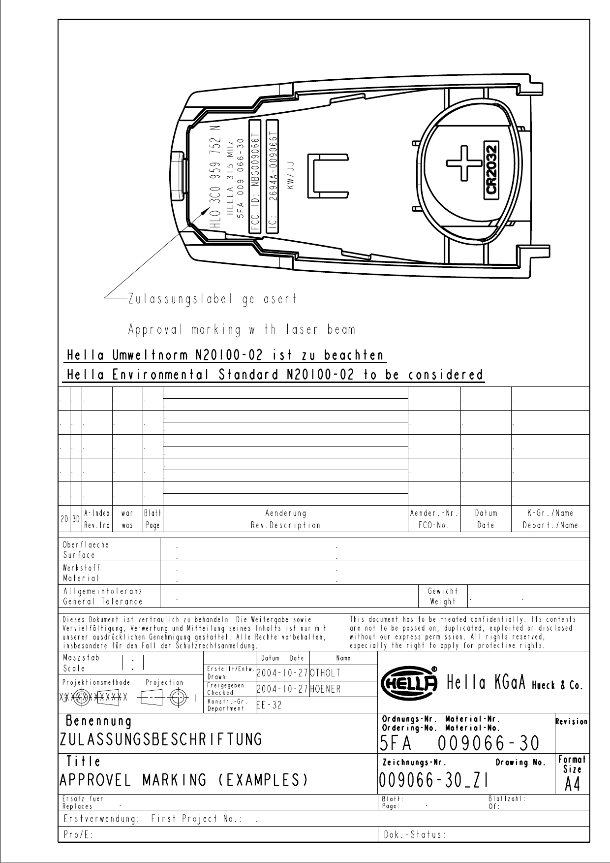
HELLA and KGaA 009066T Transmitter 5FA 009 066-30 User Manual

Hella KGaA Hueck & Co. Transmitter 5FA 009 066-30 Users Manual

Users Manual

Annex No.5                Technical Description  Users Manual Key: 5FA 009 066-30
 Hella KGaA Hueck & Co 59552 Lippstadt     Date:   2004-11-02   Processed:  K. Bödeker EE-324  Checked: Function Description 5FA009066-30_Eng_041102.doc Replacement for version dated :  Page 1 of 3    Function description  PLL radio remote control transmitter   5FA 009 066 – 30                                                                 2004-11-02    All New document EE-324 Bödeker Amend. date Amend. No. Page Amendment Gr./Name/Chkd.
 Hella KGaA Hueck & Co 59552 Lippstadt     Date:    2004-11-02  Processed:  K. Bödeker EE-324   Checked:  Replacement for version dated: Page 2 of 3  1 Circuit Description Atmel´s integrated circuit ATAR862 is the central construction element of the radio remote control transmitter. This IC is a single-package fully integrated 4-bit mask-ROM microcontroller with PLL-RF-transmitter. As an alternative the pin- and function- compatible IC T48C862 may be used which contains a Flash-ROM programmable microcontroller. ATAR862´s integrated microcontroller is the same as the stand-alone device ATAR892, and the integrated PLL-transmitter is similar to the stand-alone-device T5753. PLL-Transmitter and microcontroller are placed into a single IC-package as separate dies without any internal electrical connection. The following figure 1 shows a block diagram of the radio transmitter´s electronic circuit.         Figure 1: Block diagram of the transmitter´s electronic circuit  Four push-buttons S1 to S4 and LED D1 act as interface to the user. The microcontroller is responsible for monitoring the button signals, monitoring the power supply, encryption and encoding of the transmit data and control of RF-telegram transmission. An integrated EEPROM serves as a storage device for transmitter-specific data. The transmitter´s power supply comes from a lithium coin-cell battery CR2032. The nominal value of the supply voltage is    3 volts. Capacitor C2 blocks the supply voltage for the microcontroller part of IC1. By pressing buttons S1 to S4 logic-high level is applied to the microcontroller´s inputs BP50, BP52, BP53 or BP63. Pulldown resistors R1 to R4 are actually not mounted because all button inputs of IC1 have internal pulldown elements for termination to logic-low level. Resistors R7 and R8 are used for decoupling of the connection between the push buttons S1 and S2 from the board antenna structure. The microcontroller´s output port BP20 drives the LED D1 via Resistor R5. Switcing on and off the PLL circuit of IC1 is done by means of output port BP23, whereas the modulation signal is supplied to the PLL-transmitter via output port BP42. Capacitors C1, C4 and C11 are used for decoupling of the transmitter´s supply voltage. The PLL-part of IC1 contains  a crystal oscillator circuit with Q1 and C3 as frequency determining elements. The oscillator´s output signal is used as a reference for the transmitter´s PLL-circuit and for clocking the microcontroller via an integrated 4:1-frequency-divider.  The PLL loop-filter is fully integrated into IC1. The transmitter´s output stage is switched on and off via input PA_ENABLE. Thus the transmitted signal is OOK-modulated with the data supplied by the microcontroller via output port BP42.  An on-board resonant loop antenna is used to radiate the output signal of the transmitter circuit. Capacitors C5 and C6  determine the resonance frequency of the antenna, whereas C7, L2 and C10 are used for lowpass-filtering of the transmitters´s output signal. L1 serves as a DC-path to the transmitter´s output stage.  uC       RF-  transmitter Data On / off Clock ATAR862 Crystal 9,84375 MHz LED Voltage supply 3V S2: lock button S1: unlock button  S3: tailgate release but. S4: panic alarm button
 Hella KGaA Hueck & Co 59552 Lippstadt     Date:    2004-11-02  Processed:  K. Bödeker EE-324   Checked:  Replacement for version dated: Page 3 of 3  2 General Function While none of the buttons is pressed, the microcontroller is in sleep mode and the transmitter´s RF stage is disabled. Pressing any of the buttons S1 to S4 wakes up the microcontroller. At this time an integrated RC-oscillator is used as the microcontroller´s clock source. The crystal oscillator and the PLL circuit will now be switched on via BP23. At the end of a short stabilisation phase the clock source for the microcontroller is switched from the RC-oscillator to the output of the integrated 4:1 frequency-divider. Message Data is fed from the microcontroller to the power amplifier via output port BP42 thus modulating the RF-carrier in OOK-Mode. After all buttons have been released, transmission will stop and the PLL-circuit is disabled by switching off output port BP23. The microcontroller returns to the sleep-mode again. 3 Technical data Model designation Buttons Function 5FA 009 066–30   S1 S2 S3 S4 Unlock Lock Tailgate remote release Panic alarm Supply Voltage 3V nominal  (1 Lithium coin cell) Current consumption approx. 8 mA Operating frequency 315,0 MHz ± 100 ppm Frequency synthesis Quartz crystal stabilized PLL PLL reference frequency 9.84375 MHz  Modulation scheme Pulse Modulation (OOK) Type of transmission (ITU Designation) A1D / simplex Moduation data rate approx. 1,7 Kbit / s Signal strength max. 6mV/m @ 3m Operating temperature range -20°C ... +60°C Antenna integrated PCB loop antenna

Navigation menu