HELLA and KGaA 934692A Field Disturbance Sensor User Manual Testreport ETS 300 335
Hella KGaA Hueck & Co. Field Disturbance Sensor Testreport ETS 300 335
UserManual.wiki
>
HELLA and KGaA
>
934692A User Manual
>
Users Manual-1
Contents
1.
Users Manual-1
2.
Users Manual-2
Users Manual-1
Navigation menu
Upload a User Manual
Namespaces
Wiki Guide
HTML
PDF
Info
Views
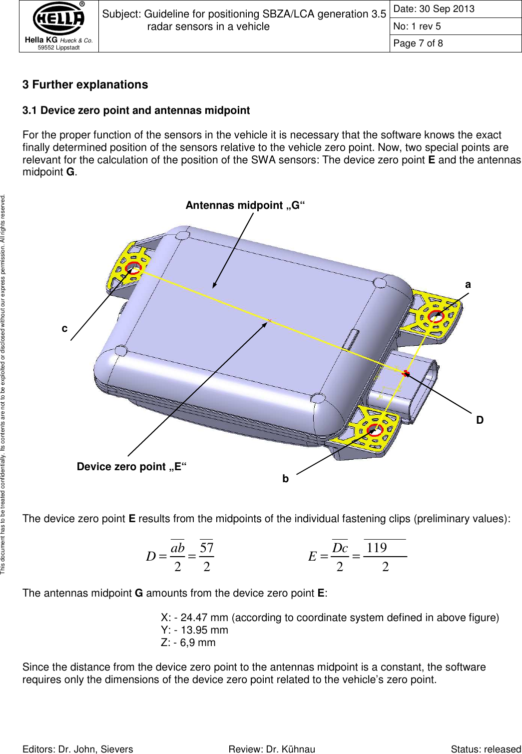
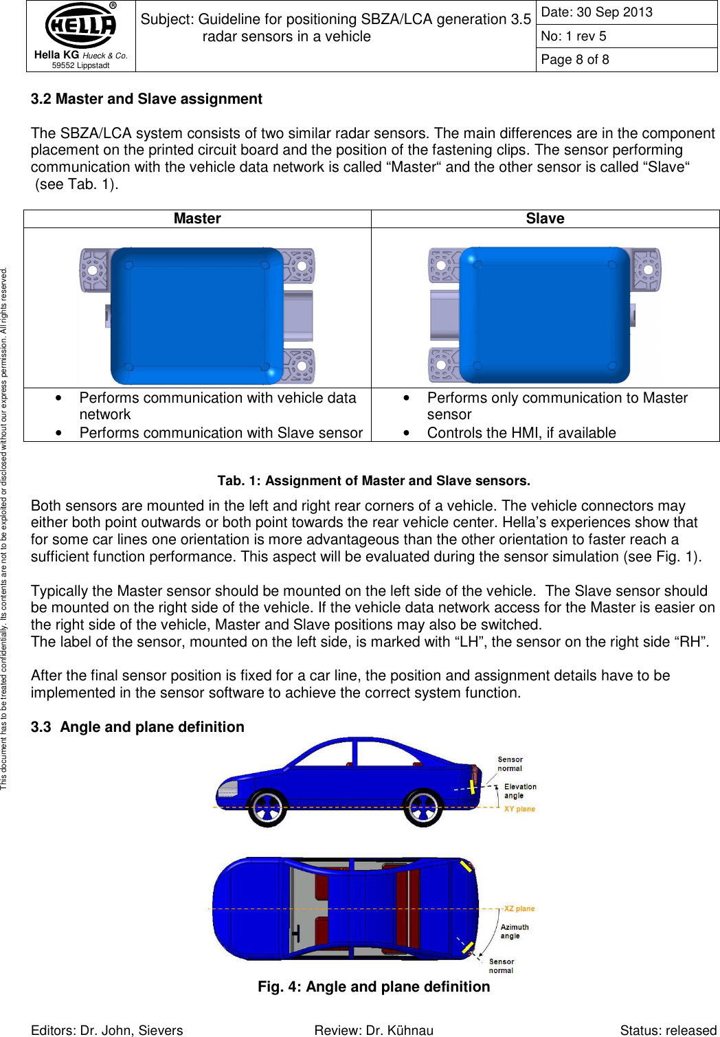
User Manual
Discussion / Help
Navigation