HES 660_MultiLock Pages 1 4_Rev_B 660 Series Installation Guide HES660Install Instructions
User Manual: HES HES 660 Series Installation Guide Installation Guide
Open the PDF directly: View PDF ![]() .
.
Page Count: 4
®Multi-Purpose Lock
Installation Instructions
1
2
4
1
ASSA ABLOY, the global leader
in door opening solutions
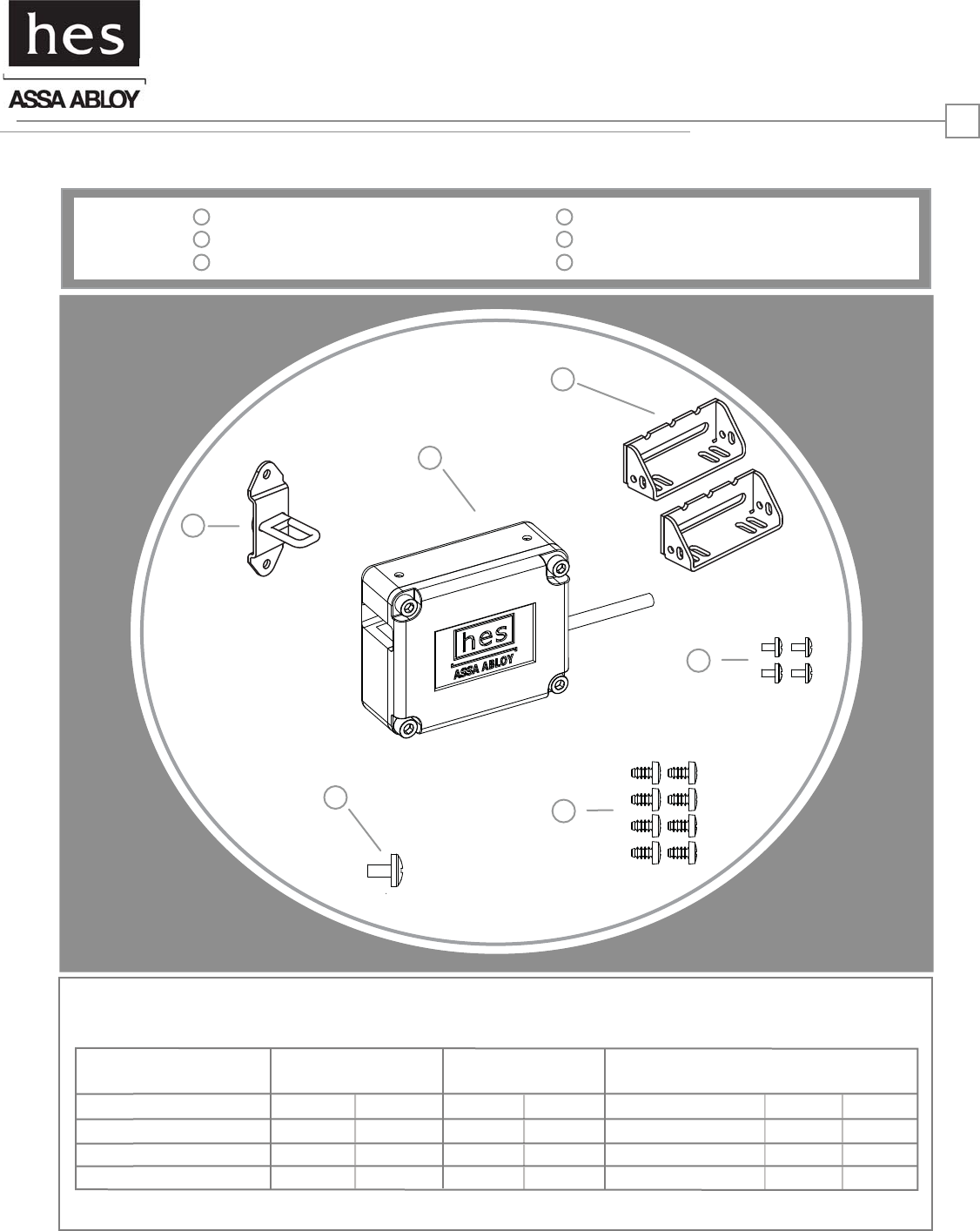
Product Components
3
SOLENOID VOLTAGE 12VDC 24VDC
ELECTRICAL RATINGS
FOR SOLENOID
CONTINUOUS DUTY
12VDC
48
24VDC
192
Resistance in Ohms
Amps Seated
Electrical Specifications
Operating Voltage +/- 10%
Watts Seated
STANDARD INTERMITTENT DUTY
PRELOAD
33
250mA 125mA
12VDC
17
24VDC
67.8
8.4 8.4
700mA 350mA
MINIMUM WIRE GAUGE REQUIREMENTS
200 feet or less
200 - 300 feet
300 - 400 feet
14 gauge
12 gauge
12 gauge
18 gauge
18 gauge
16 gauge
5
6
1
2
3
Hook Bracket Assembly
660 Multi-Purpose Lock Body
Lock Mounting Brackets
4
5
6
#6-32 X 3/16” Screws
#10 X 1/2” Screws
#8-32 X 5/8” Screw
HES, Inc.
Phoenix, AZ 85044
800-626-7590
www.hesinnovations.com
2
Installation Directions
Prepare Lock
CAUTION! Before connecting any device at the installation site, verify input voltage using a multimeter.
Many power supplies and low voltage transformers operate at higher levels than listed. Any input voltage exceeding
10% of the solenoid rating may cause severe damage to the unit and will void the warranty.
Prepare Cabinet/Drawer
Finish Installing
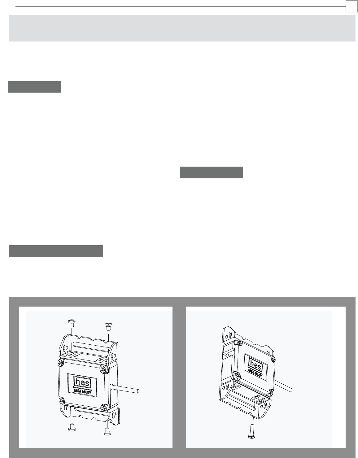
DIAGRAM 1: MOUNTING BRACKET INSTALLATION DIAGRAM 2: #8-32 X 5/8” SCREW INSTALLATION
#8-32 X 5/8” SCREW
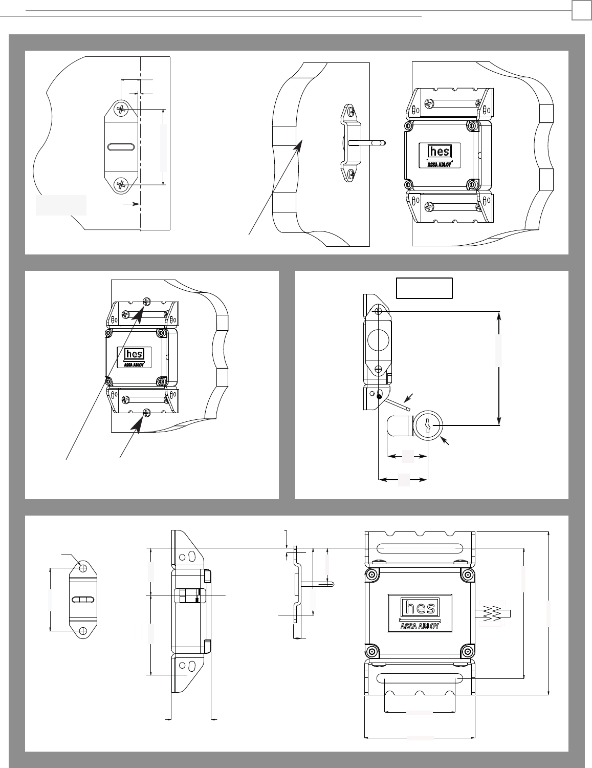
6. If lock body adjustment is needed to ensure a smooth
capture and release of the hook bracket assembly, loosen
the #10 X 1/2” and #6-32 X 3/16“ screws to adjust the
Multi-Purpose Lock Body until desired clearance is reached.
7. If additional stability is desired, drill two 1/16” pilot holes
and use two remaining #10 X 1/2” screws for final lockdown
of the Multi-Purpose Lock Body as illustrated in Diagram 6,
on Page 4.
8. If the optional key override is used, prepare the
cabinet/drawer as illustrated in Diagram 7, on Page 4.
WARNING: The Multi-Purpose Lock Body must
be wired to a power source prior to insertion of the
Hook Bracket Assembly. Failure to do so may result
in a permanently locked cabinet/drawer.
1. Attach both Lock Mounting Brackets to the
Multi-Purpose Lock Body using four #6-32 x 3/16”
screws as illustrated in Diagram 1.
2. To prevent accidental capture of the Hook
Bracket Assembly prior to the Multi-Purpose Lock
Body being wired, gently thread the #8-32 X 5/8”
screw into the #8-32 threaded hole depicted in
Diagram 2. The #8-32 X 5/8“ screw must only be
tightened snug by hand.
When installed the #8-32 X 5/8” screw will prevent
the capture of the Hook Bracket Assembly by the
Multi-Purpose Lock Body. When wiring is complete,
remove the #8-32 X 5/8” screw. The Multi-Purpose
Lock Body will now be able to capture and
electrically release the Hook Bracket Assembly.
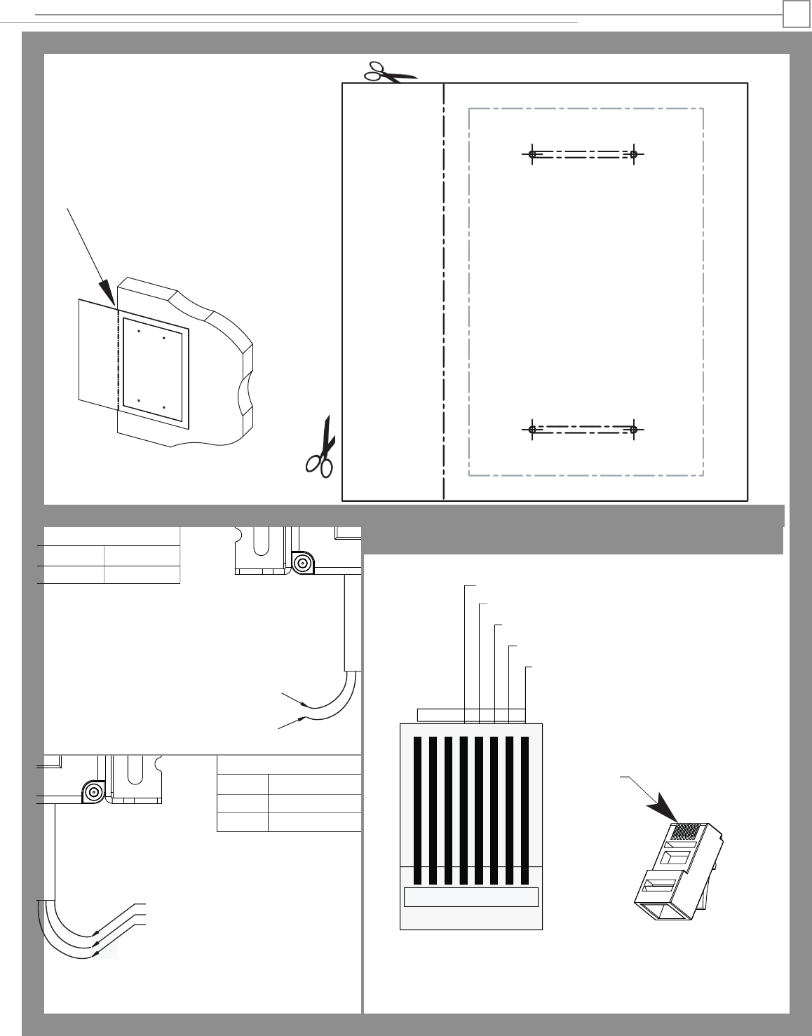
4. Refer to Diagram 4 on page 3 to connect power to the
Multi-Purpose Lock Body. If your Multi-Purpose Lock is
equipped with the RJ-45 option, a diagram for pin
assignments is also provided on page 3, Diagram 4.
If applicable, the LBSM should also be electrically
connected at this time. Remove the #8-32 X 5/8” screw
installed in step 2. Verify catch and release of the
unmounted Hook Bracket Assembly after power is
connected.
5. Mark mounting holes for the Hook Bracket Assembly as
illustrated on page 4, Diagram 5. Drill two 1/16” X 1/2”
deep pilot holes for the Hook Bracket Assembly, and mount
the Hook Bracket Assembly using two #10 X 1/2” screws.
3. Drill four 1/16” diameter pilot holes in the cabinet
using the Mounting Template on page 3, and mount
the Multi-Purpose Lock Body to the inside of the
cabinet/drawer using four #10 X 1/2” screws.
*SHOWN IN LH CONFIG
Installation Directions
DIAGRAM 6: HOOK BRACKET INSTALLATION
Align dotted line with outer edge of cabinet.
Tape Model 660 Mounting Template to inside
surface of cabinet.
Drill four 1/16” holes through paper template.
Model 660 Mounting Template
F
OLD LINE ON EDGE OF DOOR
/
DRAWER
FOLD LINE ON EDGE OF CABINET
MODEL 660
LOCK ASSEMBLY
RED +
BLACK -
LBSM WIRING*
White
Orange Normally Open
Green Normally Closed
Common
POWER WIRING*
RED
BLACK Negative -
Positive +
*If applicable
*CAUTION! The Multi-Purpose Lock
Body is provided as either a 12 or 24
volt unit. Verify the power supply
output before operating this device.
White
Orange
Green
o O g B b G br BR
12345678
PIN4: LBSM (COMMON) - BLUE
PIN5: POWER (NEGATIVE) - BLUE/WHITE
PIN6: LBSM (NORMALLY CLOSED) - GREEN
PIN7: POWER (POSITIVE) - BROWN/WHITE
PIN8: LBSM (NORMALLY OPEN) - BROWN
Clip is pointed
away from you
RJ-45 PLUG
PIN1
DIAGRAM 3: MOUNTING TEMPLATE
DIAGRAM 4: POWER & LBSM SWITCH WIRING
RJ-45 OPTION
3
Inside surface
of cabinet
Left hand
config
shown
7/16”
1/16”
1-11/16”
1”
[25.4]
1-11/16”
[43.1]
15/16”
[23.3]
1/8”
[3.8]
1”
[25.3]
1-5/8”
[40.6]
2-5/16”
[58.4]
3-3/8”
[85.4]
2-11/16”
[68.5]
3/16”
[5]
1-11/16”
[43.1]
3/16”
[5]
DIAGRAM 5: HOOK BRACKET INSTALLATION
X=1/4” + R1
Y= 2-1/8” + R1
X
R1
PADDLE: 660
KO OPTION
MOUNTED TO
DOOR/DRAWER
1/4” + R1
DIAGRAM 6: FINAL LOCKDOWN DIAGRAM 7: OPTIONAL KEY OVERRIDE
DIAGRAM 8: DIMENSIONS
4
Installation Directions
Inside surface
of Cabinet
2-1/8” + R1
Y
3056006.001 rev B.
© 2012 HES, Inc.
(2) #10 X 1/2” SCREWS FOR
FINAL LOCKDOWN
1-7/8”
[46.9]
