HES 3085006.001_Rev B KS200 640 Server Cabinet Lock Installation Guide KS200Installation Instructions
User Manual: HES HES KS200-640 Server Cabinet Lock Installation Guide Installation Guide
Open the PDF directly: View PDF ![]() .
.
Page Count: 12
Part Number 3085006.001, Rev. B 1
K200-622
Cabinet Lock Series
Installation Instructions
HES, Inc.
Phoenix, AZ
1.800.626.7590
www.hesinnovations.com
Machine
screwwith
washer
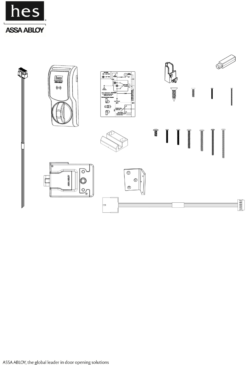
Package Contents
Strike Plate 6-32 screws
2X
5/16”
1”
1-5/8”
1-1/4”
1-3/4”
2‐1/2”
2X 1X
3X
2X
2X
Shaft Extension
0-80x½”
2-56x3/8”
2-56x1-1/4”
Key Override Paddle
2X
1X 1X
6 x 1/2”
3X
1-7/8”
2X
Recommended Tools
Optional:
Cam lock for key override
Double door bracket
Lock Body
Drill, Drill bits: 5/32”, 1/2”
Approved Credential:
i.e. iCLASS or Prox ID card
Phillips drivers P0, P2
Pencil, Wire Stripper
Voltage: 12–24 VDC ±10% (Power Supply not provided)
K200-622 (Reader) Current Consumption:
12 VDC: 38 mA peak for Red and Green LED only
226 mA peak for Red and Green LED and Motor Drive
24 VDC: 17 mA peak for Red and Green LED only
118 mA peak for Red and Green LED and Motor Drive
Operating Temperature: -10C to 50C
Holding Force: 250 lbs
Lock Reader
Specifications
Mounting
Template
Interface Cable, Lock Side
Interface Cable,
System Side

Part Number 3085006.001, Rev. B 2
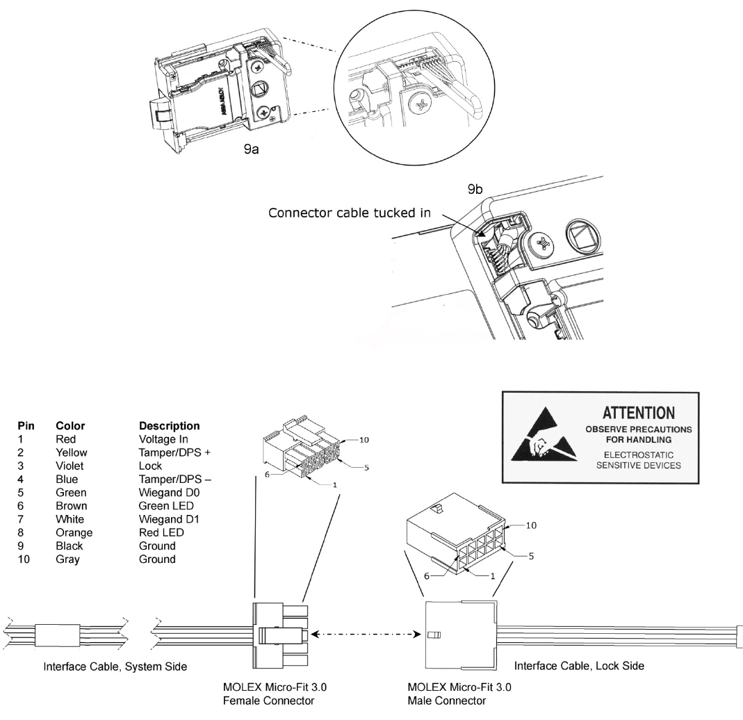
External Interface Signals Summary:
From/To Lock Signal
Name
Lock Signal
Direction and Wire
Color
Electrical Interface Logic
P1-1/J1-1 Vin Input,
Red/24 AWG Power to Reader Input Power
P1-12/J1-2 Tamper / Door
Position +
Output,
Yellow/24 AWG
Dry Contact
(0–35 VDC, <100mA)
Open = Unlocked
Closed = Locked
P1-3/J1-3
Lock Input,
Violet/24 AWG
Wetted Relay Contact
Closure
(0–35 VDC)
Active High
P1-4/J1-4 Tamper / Door
Position –
Output,
Blue/24 AWG
Dry Contact
(0–35 VDC, <100mA)
Open = Unlocked
Closed = Locked
P1-5/J1-5 Wiegand Data 0 Output,
Green/24 AWG 0–5 VDC Active Low
P1-6/J1-6 Green LED Input,
Brown/24 AWG 0–5 VDC Active Low
P1-7/J1-7 Wiegand Data 1 Output,
White/24 AWG 0–5 VDC Active Low
P1-8/J1-8 Red LED Input,
Orange/24 AWG 0–5 VDC Active Low
P1-9/J1-9 Ground Input,
Black/24 AWG – –
P1-10/J1-10 Ground Input,
Gray/24 AWG – –
LED Function: LED states are controlled and defined by the User’s EAC. Enabling the red and green LEDs on
the K200 occurs via an active low (ground) signal.
Output Type: SIAAC-01-1996 Wiegand Output Compliant.
FCC Part 15, Compliant, Industry Canada Compliant
BHMA: A156.3, A156.36, A156.25 Compliant
NOTE: Contact HID Global Technical Support at (866) 607-7339 for additional configuration cards to enable
the credential capabilities of “iCLASS Elite” and “NFC over HCE.”
Credentials Supported: 125 kHz Proximity or 13.56 MHz iCLASS, iCLASS Elite, iCLASS SEOS, iCLASS SE,
ISO 15693 ICLASS, ISO 14443A Mifare, Mifare Plus, Desfire SE, Desfire EV1, and NFC over HCE.
Part Number 3085006.001, Rev. B 3
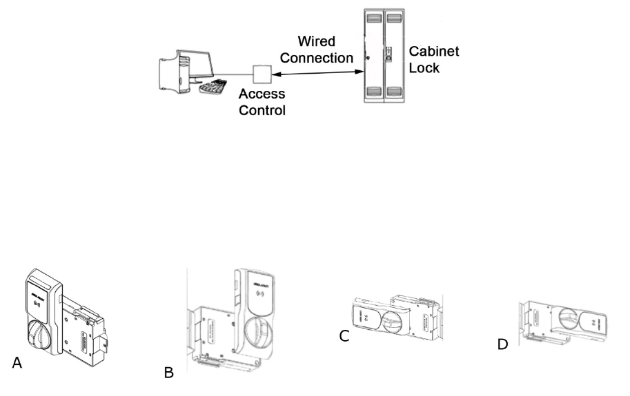
SYSTEM OVERVIEW
The K200-622 wired cabinet lock (K200) extends access control to a cabinet or drawer. The K200 lock is capable
of reading radio-frequency identification (RFID) credentials and providing that credential data to an electronic
access control (EAC) system via Wiegand data signaling. The EAC is responsible for determining whether user
access should be granted or denied. When the EAC provides an active-high unlock signal to the lock in the access
granted case, the K200 drives a motor to complete the unlock/lock cycle. EAC indication of user access/denial is
provided to the user by way of LED control inputs on each lock. Additional lock monitoring features (e.g., door
position, tamper) are monitored within the lock and status of each is provided to the EAC.
MOUNTING THE LOCK
NOTE: The K200 reader and lock body can be oriented in several ways to accommodate various cabinets and
drawers. When selecting an orientation, it should be noted that some reader orientations may prevent use
of the key override function. For example, in the door handing shown here, the key override paddle cannot
be accessed in orientation “A”, but it can be accessed in orientations “B,” “C” and “D”.
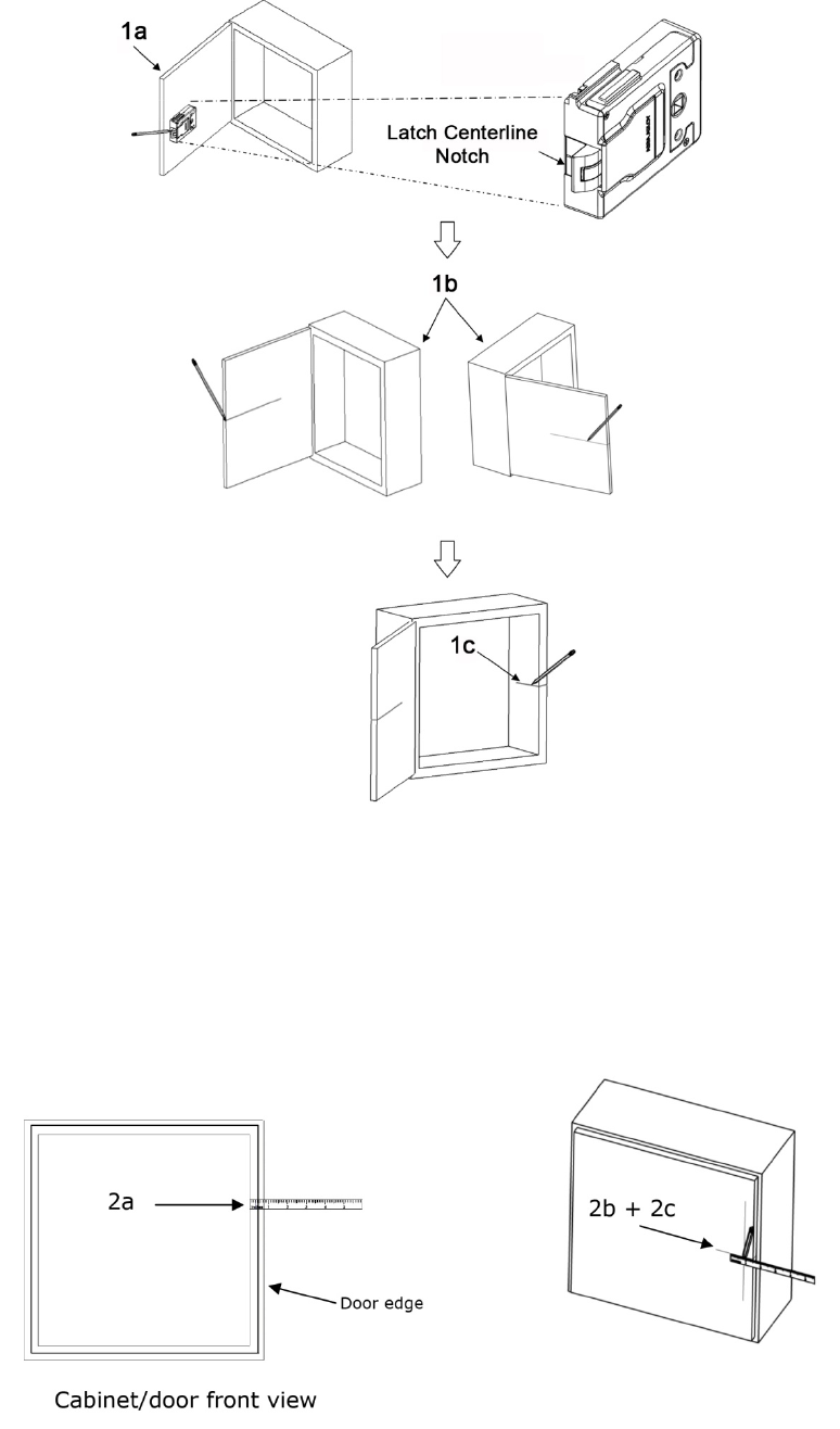
1. ESTABLISH the horizontal centerline of the latch.
a. HOLD the lock body to the inside of the door and POSITION it generally where you would like it to mount.
b. LOCATE lock centerline notch on the latch, and MARK this point on the inside of the cabinet door using a
pencil.
c. DRAW the horizontal latch centerline from this mark on the inside of the cabinet door and TRANSFER it to the
outside of the cabinet door.
d. TRANSFER this centerline to the inside of the cabinet or the second door on a double-door cabinet.
Part Number 3085006.001, Rev. B 4
2. TRANSFER the location of the inside wall of the cabinet to the door.
a. MEASURE the horizontal distance between the inside edge of the cabinet and the door edge.
NOTE: The drawn line depicts the location of the strike mounting surface.
b. LOCATE the lock centerline notch on the latch and MARK this point on the inside of the cabinet door using a
pencil.
c. DRAW the horizontal latch centerline from this mark on the inside of the cabinet door and TRANSFER it to the
outside of the cabinet door.
Part Number 3085006.001, Rev. B 5
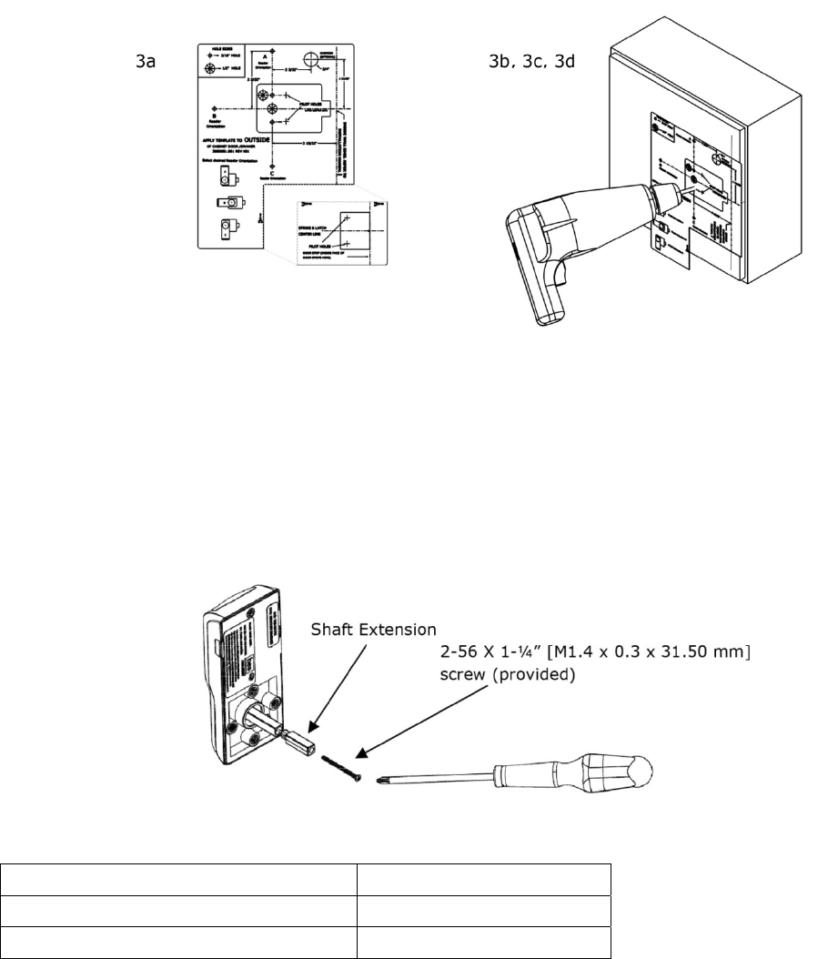
3. PLACE and USE the Lock/Reader Template.
NOTE: The orientation will be reversed for a right hand door.
a. CUT through line to separate the Strike Plate Template.
b. PEEL OFF the protective layer of the Lock Template, ALIGN it to both the latch centerline and the line depicting
the inside wall of cabinet, and PRESS to secure.
NOTE: Two of the holes in the following step are 3/16” [4.76 mm] diameter and two are 1/2” [12.70 mm]
diameter. The two pilot holes are 1/16” [1.59 mm].
c. DRILL four holes and two pilot holes through the cabinet, as shown in the figure below.
d. DRILL only one 3/16” [4.76 mm] hole, depending on the desired Antenna/Reader orientation.
e. IF the optional key override will be installed,
THEN GO TO Step 5.
f. REMOVE the lock template from the door.
4. INSTALL the shaft extension.
a. IF the cabinet door thickness is greater than 1/2” [12.70 mm] (see Table 1),
THEN INSTALL the Shaft Extension to the Antenna/Reader to ensure proper engagement into the lock.
b. INSTALL the Shaft Extension to the shaft as shown in the figure, and firmly TIGHTEN the screw.
Table 1
Door Thickness Extension Shaft Used?
1/16” [1.59 mm] – 1/2” [12.70 mm]
> 1/2” [12.70 mm] – 1-1/2” [38.10 mm]
Yes
Part Number 3085006.001, Rev. B 6
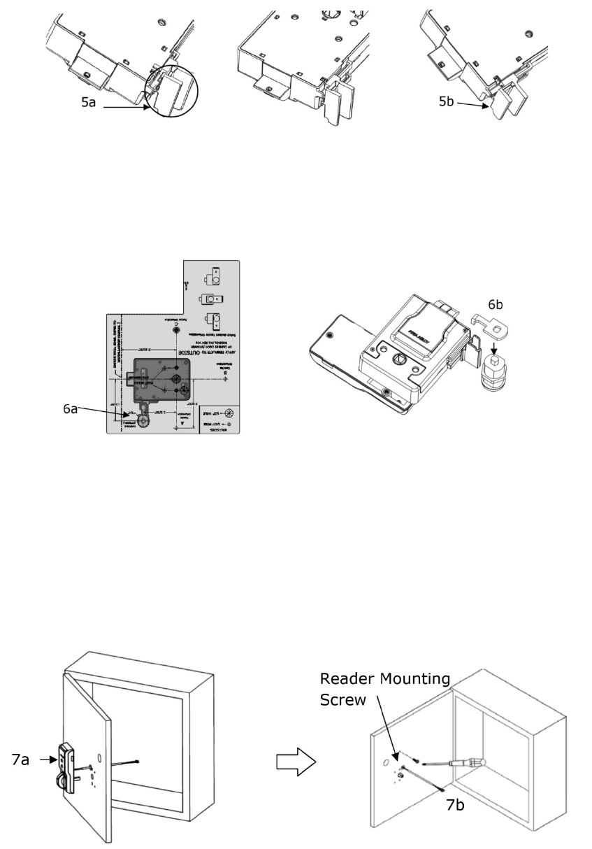
5. IF a Cam Lock key override will be used,
AND the orientation allows for installation,
THEN INSTALL the Key Override Paddle.
a. INSERT the paddle’s arm into the opening shown, and ALIGN the rails of the paddle to the ones on the lock.
b. SLIDE the paddle gently until it stops.
6. PREPARE the Key Override Door.
NOTE: The Cam Lock is optional and must be obtained by others.
a. IF a Key Override is used,
THEN MARK and DRILL a hole for a 3/4” [19.05 mm] Cam Lock in the door using the template as a guide.
b. INSTALL the optional Cam Lock with the Cabinet Lock as shown in the figure.
7. INSTALL the Antenna/Reader.
CAUTION
Pinching the wires may prevent the Reader and Lock from properly functioning.
a. PLACE and HOLD the antenna/reader to the outside of cabinet, routing the wire through the 1/2” [12.70 mm]
offset hole, and ENSURE the knob is in the locked position in the vertical.
NOTE: Using the table below will help determine the length of the top mount screw needed, based on the
thickness of the cabinet door.
b. INSTALL the top mount screw to attach the antenna/reader to the outside case.
Part Number 3085006.001, Rev. B 7
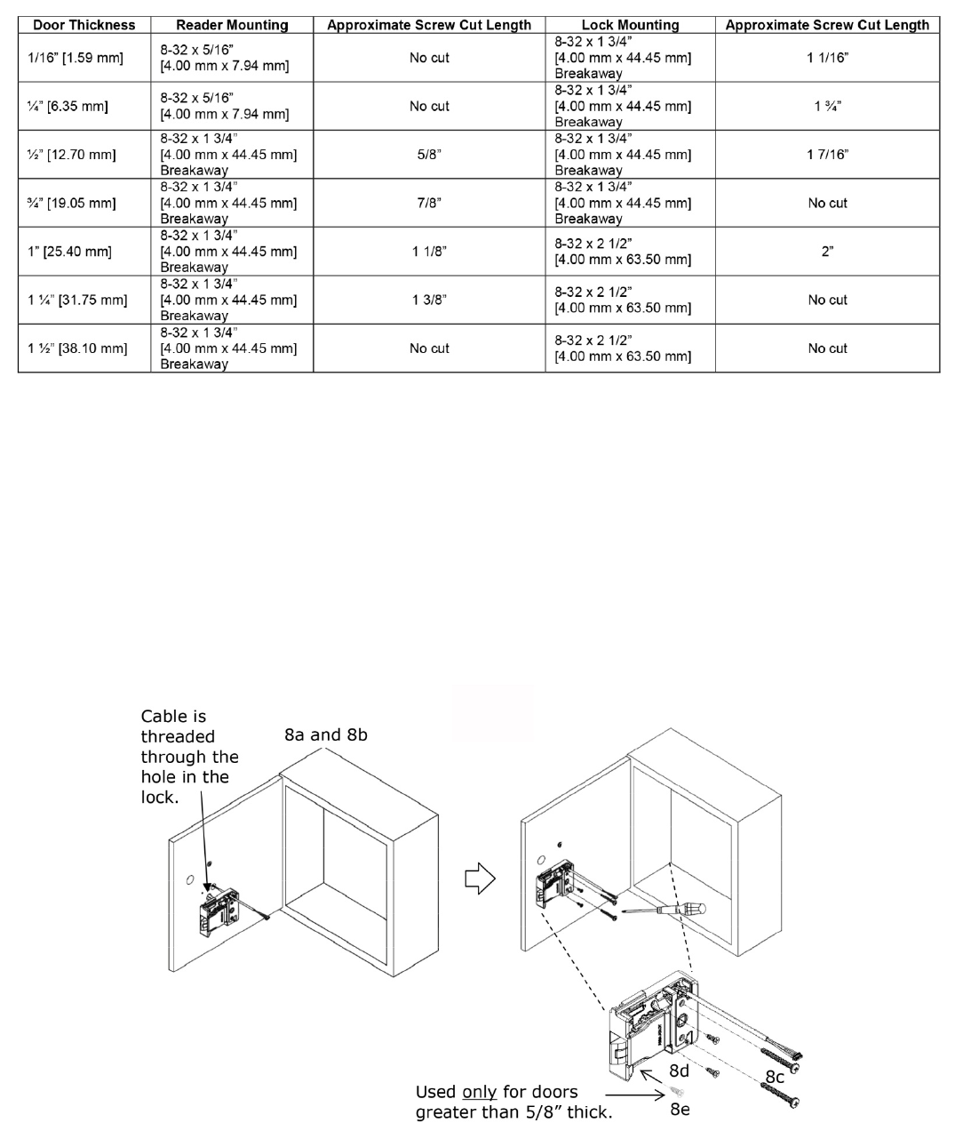
8. INSTALL the lock.
a. REMOVE the cover from lock.
b. PLACE the lock on the inside of the door, threading the cable through the lock.
c. ATTACH the lock to the antenna/reader using two 8-32 [4.00 mm] lock mount screws (see Table 2 for length),
and TIGHTEN the screws.
d. INSTALL the two #6 [3.5 mm] self-threading screws, and TIGHTEN.
NOTE: The third #6 [3.5 mm] self-threading screw is important to achieve maximum holding force for doors
greater than 5/8” [15.88 mm] thick.
e. INSTALL the third #6 [3.5 mm] self-threading screw only if the door is greater than 5/8” [15.88 mm] thick,
using the lock as a guide, and TIGHTEN.
Part Number 3085006.001, Rev. B 8
9. CONNECT the antenna/reader wire to the lock body.
NOTE: The antenna/reader wire connector is engineered to fit only one way.
a. INSERT the antenna/reader wire connector, ensuring correct orientation
b. TUCK excess cable into the lock body.
c. ATTACH the cover.
10.
CONNECT the 10-position Molex Micro-Fit Cable between the K200 and the EAC.
Part Number 3085006.001, Rev. B 9
NOTE: It is recommended that 10-conductor, 24 AWG, cable be used.
11. ENSURE the following power cabling guidelines are followed:
Wire AWG Supply Voltage Allowed Cable Length (ft.)*
20 AWG
12 872
24 6679
22 AWG
12 548
24 4201
24 AWG
12 345
24 2641
* Round trip loss. V = 2 x I x R x xft xft = V / (2 x I x R)
12. POSITION the cable out of the way, as required.
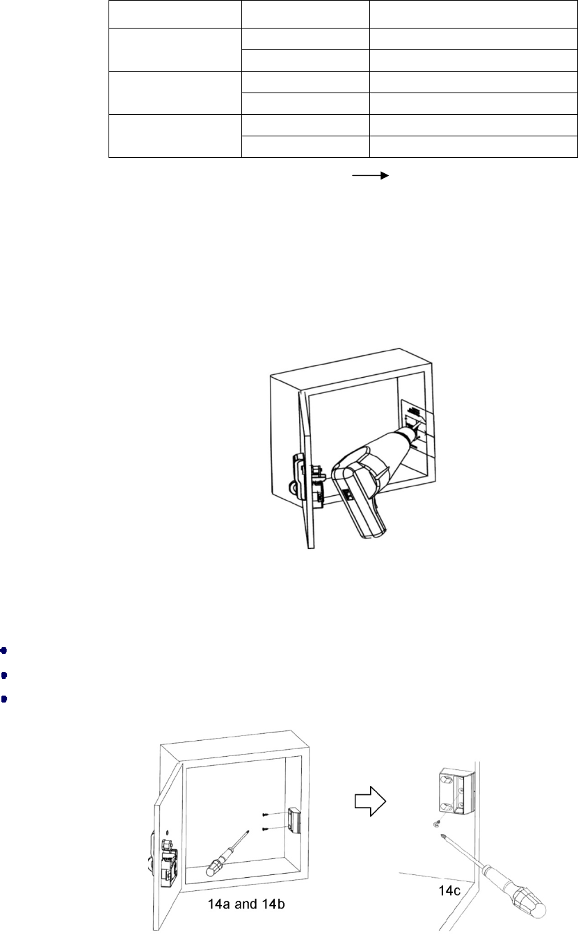
13. PREPARE for the single door strike plate.
a. PEEL OFF the protective layer of the Strike Plate Template and ALIGN it to both the latch centerline and the
cabinet edge.
b. DRILL the two pilot holes shown on the template.
c. REMOVE the template.
CAUTION
The Installer must ensure that the lock can be opened before closing the cabinet door.
14. INSTALL the single door strike plate.
PLACE the strike plate over the pilot holes, and INSERT and TIGHTEN the two screws in the slotted holes.
CLOSE the door to verify installation, and ADJUST the strike plate if necessary.
INSERT and TIGHTEN the lock down screw on the strike plate.
Part Number 3085006.001, Rev. B 10
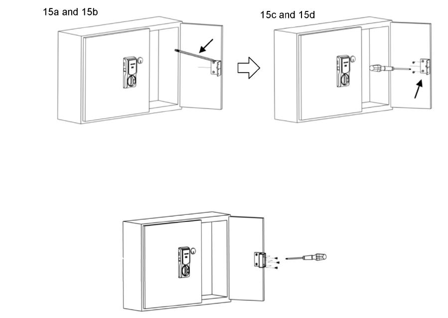
15. INSTALL for the double-door strike plate mounting bracket. (OPTIONAL)
NOTE: The double-door strike plate bracket requires that one door can be secured.
a. PLACE the bracket on door, making sure it aligns with the mark made in Step 2c and the edge of the door.
b. MARK the door.
c. REMOVE the bracket and DRILL pilot holes at the two marks.
d. INSTALL the bracket using the provided mounting screws.
16.
INSTALL the double-door strike plate.
a. PLACE the strike plate over the holes on the bracket.
b. INSERT and TIGHTEN the three 6-32 x 5/16” (3.5 mm x 7.94 mm) provided screws.
FCC Statement
This device complies with part 15 of the FCC Rules. Operation is subject to the following two conditions:
(1) this device may not cause harmful interference, and
(2) this device must accept any interference received, including interference that may cause undesired operation.
IC Statement
This device complies with Industry Canada license-exempt RSS standards(s). Operation is subject to the following
two conditions:
(1) this device may not cause interference, and
(2) this device must accept any interference, including interference that may cause undesired operation.

Part Number 3085006.001, Rev. B 11
CE Statement
HES hereby declares that these proximity readers are in compliance with the essential requirements and other relevant provisions of
Directive 1999/5/EC (http://ec.europa.eu/enterprise/sectors/rtte/files/guide2009-04-20_en.pdf).
Conformité aux normes FCC
Cet appareil est confrome à la Partie 15 des règlements de la FCC. Son fonctionnement est souimes aux deux
conditions suivantes:
(1) cet appareil ne peut causer d’interférences, et
(2) cet appareil doit accepter toute interference, y compris des interférences qui peuvent provoquer un
fonctionnement indésirable du périphérique.
Conformité aux normes IC
Cet appareil est confrome avec Industrie Canada exempt de license RSS standard(s). Son fonctionnement est
souimes aux deux conditions suivantes:
(1) cet appareil ne peut causer d’interférences, et
(2) cet appareil doit accepter toute interference, y compris des interférences qui peuvent provoquer un
fonctionnement indésirable du périphérique.
Conformité aux normes CE
HES déclare par la présente que ces lecteurs à proximité sont conformes aux exigences essentielles et aux autres
stipulations pertinentes de la Directive 1999/5/CE (http://ec.europa.eu/enterprise/sectors/rtte/files/guide2009-04-
20_en.pdf).
Part Number 3085006.001, Rev. B 12
For Technical Support
please call 1-800-626-7590
For information on other HES cabinet lock solutions,
visit hesinnovations.com
© 2015
,
Hanchett Entry Systems, Inc., an ASSA ABLOY Group Company.
