HID Global 05866001T1 RFID Reader/Writer User Manual 1
HID Global Corporation RFID Reader/Writer 1
User manual

Integrated Information Systems Group
8201 E. McDowell Road
Scottsdale, AZ 85252-1417
Exhibit 8
Page 1 of 21 FCC ID: E9U05866001T1
5/24//01
Exhibit 8 – Users Manual
BiStatix
BDR-1000
RFID Tag Reader/Programmer
FCC ID: E9U05866001T1
Model No. BDR-1000
8.0 BDR-1000 Users Manual
May 4th,2001 K01994-001 Rev 2
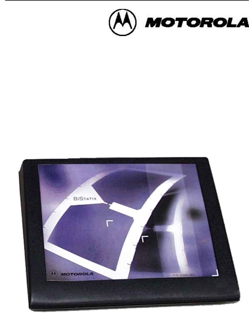
BiStatixTM Desktop Reader / Writer
BDR-1000
Operation Manual

May 4th, 2001 K01994-001 Rev 2 2
Copyright, Trademarks, and Patent Provisions: © 2000 Motorola Corporation, reserves all
rights including patents, copyrights, trademarks, trade names, and all other intellectual property
rights worldwide. No reproduction, adaptation or translation is allowed without prior written
permission from Motorola Corporation. Motorola Corporation reserves the right to change any
product description and or specification contained here without prior notice.
BiStatix products are covered under one or more of the following patents: 6,018,299; 6,040,773;
6,091,332; 6,094,138; 6,107,920; 6,107,921; 6,130,613; 6,147,605; 6,157,300; 4,818,855;
5,099,277; 5,221,831; 5,600,683; 6218942. Others are available and pending worldwide.
FCC Compliance: This equipment has been tested and found to comply with the limits for a
Class B digital device, pursuant to Part 15 of the FCC Rules. These limits are designed to provide
reasonable protection against harmful interference in an installation. Changes or modifications
not expressly approved by the party responsible for compliance could void the user’s authority to
operate the equipment. This equipment generates, uses and can radiate radio frequency energy
and if not installed and used in accordance with instruction, may cause harmful interference to
radio communications. However, there is no guarantee that interference will not occur in a
particular installation. If this equipment does cause harmful interference to radio or television
reception, which can be determined by turning the equipment off and on, the user is encouraged
to try to correct the interference by one or more of the following measures:
• Re-orient or relocate the receiving antenna.
• Increase the separation between the equipment and receiver.
• Connect the equipment into an outlet on a circuit different from that to which the receiver is
connected.
• Consult the dealer of an experienced radio/TV technician for help.
Any change or modification to this product voids the user’s authority to operate per FCC Part 15
Subpart A Section 15.21 regulations.
CE
This product, when marked with the CE symbol, complies with the European Community Council
Directives 89/336/EEC and 99/5/EC R&TTE provided the installer/user adheres to the instructions
detailed in this manual. This product, when marked with the CE symbol, is in compliance with EN
300 330, ESTI EN 300 683 with the referenced standards EN 55022 (Class B), EN 61000-4-2,
EN 61000-4-3, EN 61000-4-4, EN 61000-4-6, and the Low Voltage Directive EN 60950.

May 4th, 2001 K01994-001 Rev 2 3
Thank you for purchasing the Motorola BiStatixTM BDR-1000 or BDK-1000. We hope the tools
are fruitful in your technology evaluation.
YOUR DEVELOPMENT TOOLS…
The BDR-1000 is the BiStatix Desktop Reader / Writer. The BDK-1000 is the BiStatix
Development Kit, which contains a BDR-1000, DLL’s, an API and a tag kit.
The BDK-1000 kit enables further evaluation of BiStatix capacitively coupled RFID technology,
expanding the capabilities beyond reading tags, enabling you to construct your own tags,
experiment with various tag form factors, program custom data utilizing the provided API and
DLL’s and build upon sample code.
Using the BDR-1000 hardware, the user may experiment with two fundamental versions of the
technology – DiPole and MonoPole coupling. The hardware supports either RS-232, RS-422 or
RS-485 serial communication interfaces.
Contents:
Item Description BDR-1000 BDK-1000
1 BDR-1000 BiStatix Desktop Reader /
Writer √
√√
√ √
√√
√
2 Universal Power Supply √
√√
√ √
√√
√
3 Standard U.S. Power Cord √
√√
√ √
√√
√
4 European Power Cord √
√√
√ √
√√
√
5 RS-232 serial communication cable √
√√
√ √
√√
√
6 This introduction / manual √
√√
√ √
√√
√
7 CD with API, DLL’s, sample code &
soft copy software instruction set √
√√
√
8 10-pack letter-sized “Tear-It” tags √
√√
√
9 10-pack index card-sized cards √
√√
√
10 40-pack letter-sized electrode sheets √
√√
√
11 Roll of (100) interposers √
√√
√

May 4th, 2001 K01994-001 Rev 2 4
Table of Contents
1 PRODUCT SPECIFICATION ................................................................................ 6
2 INTRODUCTION..................................................................................................... 8
2.1 Theory of Operation............................................................................................8
2.2 Getting Familiar with the BDR-1000 (Tag Orientation) ....................................9
2.3 BDR-1000 Rear Panel....................................................................................... 10
3 INSTALLATION & WIRING............................................................................... 11
3.1 Setup .................................................................................................................. 11
3.2 Host Interface Wiring........................................................................................12
3.3 Grounding Requirements .................................................................................. 12
4 OPERATION........................................................................................................... 13
4.1 Reader Operation.............................................................................................. 13
4.2 Programmer Operation.....................................................................................13
4.3 Indicators .......................................................................................................... 14
5 BDR-1000 CONFIGURATION PARAMETERS ................................................ 15
6 BDR1000 to BXR610 Compatibility...................................................................... 16
7 TROUBLESHOOTING ......................................................................................... 17
8 ADDITIONAL INFORMATION .......................................................................... 18
8.1 Mechanical Dimensions .................................................................................... 18
8.2 Copyrights Patents and Trademark Credits ..................................................... 19
8.3 Warranty............................................................................................................ 19
8.4 RMA (Return Material Authorization) .............................................................. 19
8.5 Contacting Customer Support........................................................................... 19

May 4th, 2001 K01994-001 Rev 2 5
Revisions List
rev date description of change author
1 April 26,2001 Initial Draft Greg Hassman
2 May 4, 2001 Updated per Team input Greg Hass man
List of Figures
Figure 1 Operational Functional Block Diagram
Figure 2 BDR-1000 Label
Figure 3 BDR-1000 Rear Panel
Figure 4 Hook Up Diagram
Figure 5 RJ-485 Cable Assembly
Figure 6 AC Supply Grounding
Figure 7 BiStatix Read Mode, Monopole Tag Presentation
Figure 8 BiStatix Program Mode Di-pole Tag Presentation
Figure 9 BDR-1000 Mechanical Dimensions

May 4th, 2001 K01994-001 Rev 2 6
1 PRODUCT SPECIFICATION
Input Voltage:
AC Line (note 1)
100V to 240 VAC
50 Hz to 60 Hz
Notes:
1. The BDR-1000 electronics module requires DC voltages of +/- 12 and +5 volts. A
universal power supply (APX SP25970M ) is provided with the BDR-1000. This
supply has been approved for use with the electronics module in the countries of
intended operation of this product. Use of any other power supply is not
recommended by Motorola and will void the product’s warranty and may affect its
performance. Replace the power supply only with an APX SP25970M Power
Supply.
2. Do not use the equipment’s power supply for any other equipment. Doing so will
affect the equipment operation.
Typical Read Range:
Monopole ~ 10.9 cm (4.3 inches)
Dipole ~ contact
Typical Write Range:
Monopole ~ 6.6 cm (2.6 inches)
Dipole ~ contact
Typical Monopole Read and Write Ranges were determined by hand presentations of
a 5 cm x 7.6 cm (2” x 3 “) tag with a “bow tie” antenna pattern and a BXI – 5
Interposer in a laboratory environment. Actual performance will vary with any
particular installation. You should be able to reach these typical values if care is
taken to insure a proper installation and presentation of the tag.
Frequency of Operation:
Excitation Frequency ~ 125 kHz
Exciter Modulation ~ On/Off Keyed
Environmental:
Operating Temperature ~ 10 °C to 40 °C
Storage Temperature ~ -25 °C to 50 °C
Water Resistance ~ The BDR-1000 is not water resistant.
Chemicals ~ Mild detergent cleaners.
May 4th, 2001 K01994-001 Rev 2 7
Indicators:
Visual ~ Tri-color LED
Audible ~ Beeper
Enclosure:
Weight ~ 0.7 kg (1.5 pounds)
Material ~ ABS
Form Factor ~ see fig. 7
Communication Interfaces:
RS-232, RS-422, RS-485
Standard serial communication protocols are:
• Bits per second 9.6 to 38.4 Kbps (selectable by the host)
• Data bits 8
• Parity None
• Stop Bits 1
Default condition is RS-232 at 9600 bps.
Certifications:
When appropriately marked the product is certified as follows:
FCC Class B Digital Device (Part 15)
FCC ID Number E9U05866001T1
CE Compliance per R&TTED
EN 300 330
EN 300 683
EN 60950
CB Compliance
May 4th, 2001 K01994-001 Rev 2 8
2 INTRODUCTION
The BDR-1000 is a device (aka transceiver) that reads and writes Bistatix Tags. It operates
in both DiPole and MonoPole modes and it is intended for indoor use only.
The hardware supports either RS-232, RS-422 or RS-485 serial communication interfaces
and has provisions for an external antenna (future option). A standard female DB-9 connector
is provided for the RS-232 and two standard RJ-45 connectors are provided for RS-485/422
(one input, one output).
The transceiver includes a power switch, a visual status indicator and an audible indicator. In
addition, the package is supplied with an international power supply, a U.S. power cord, a
European power cord and a RS-232 serial cable.
The BDR-1000 can read tag data continuously, read tag data on command and program tag
data on command.
2.1 Theory of Operation
BiStatix is a non-resonant Capacitive or Electric field RFID technology. Passive RFID
tags derive their power and clock signals externally, from the excitation field of a nearby
transceiver, such as the BDR-1000. The tags respond with their data. The exciter can
be modulated to write data to a tag. BiStatix transceivers operate in DiPole or
MonoPole mode.
The DiPole mode is typically used where the tags are positioned in free space, not
coupled to a ground reference. It is also used in environments where tag orientation is
controlled or where very small tags are required. The BDR-1000 essentially operates in
DiPole mode when a tag is placed on the surface of the reader (hands free).
The MonoPole mode is the most common, offering greater flexibility (e.g. orientation
independence) and the best overall performance. It is typically used where a ground
reference is accessible (e.g. when a tag is coupled to a person, a conveyor, a cart, or
any other conductive object, referenced to ground). Here, one of the two tag electrodes
is preferentially coupled to the transceiver and the second electrode is preferentially
coupled to a ground reference.
Figure 1 Operational Functional Block Diagram
MonoPole S
y
stem
Tag Data
Ta
g
(Ground Reference)
Person
Or
Ob
j
ect
Serial Communications
(RS-232, RS-422, RS-485)
Universal
Power Supply
100-240
VAC, 50/60
Hz
Grounded
Su
pp
l
y
Hos
t
BDR-1000
Coupled to
Person or
Object
Ta
g
Ta
g
Data
Reference /Return Path
Power, Clock,Commands
DiPole S
y
stem
May 4th, 2001 K01994-001 Rev 2 9
GROUNDING:
BiStatix technology requires that the power supply ground for proper operation. Efforts
must be made to insure that the AC source provides an adequate ground to insure that
exciter current has a return path. If a grounded A.C. receptacle is not available, use a
3-to-2 prong adaptor and connect the ground lug to an earth ground. Failure to do so
can result in erroneous host communication and poor transceiver performance. This
should be the first item of investigation if a unit’s performance is suspect.
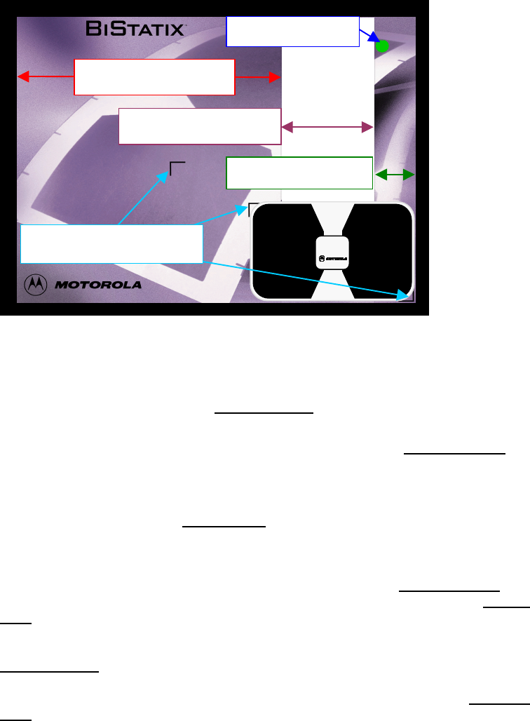
2.2 Getting Familiar with the BDR-1000 (Tag Orientation)
Figure 2 BDR-1000 Label
As depicted above, there are three distinct antenna zones on the BDR-1000. The
largest section, to the left, is the Excitation Zone. This excitation antenna provides
power, clock and command signals to the tag.
The “faded” section to the right of the Excitation Zone is the Interposer Zone. It
guides proper positioning of tags for the DiPole mode of operation. This zone
establishes the position where the interposer must be located when a tag is placed
on the transceiver.
On the rightmost side is the Ground Zone. In the DiPole mode it provides a ground
reference path for the tags, which are placed directly on the transceiver (i.e. hands
free).
In DiPole mode the tag’s interposer must be positioned in the Interposer Zone with
one electrode preferentially coupled to the exciter zone and the other to the Ground
Zone. The tag size illustrated above conveniently positions itself properly when
registered to the lower right corner. Larger tags may require that right edge of the tag
hang over the edge of the BDR – 1000 to properly position the device over the
Interposer Zone.
In MonoPole mode one antenna of the tag should be presented to the Excitation
Zone. The other should be grasped by the presenter.
Status LED
Ground Zone
Interposer Zone
Card Registration
Excitation Zone
Status LED
Ground Zone
Interposer Zone
Card Registration
Excitation Zone
May 4th, 2001 K01994-001 Rev 2 10
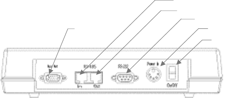
2.3 BDR-1000 Rear Panel
Figure 3 BDR-1000 Rear Panel
Power Switch
D.C. Power In
p
ut
RS-232
(
DB-9F
)
RS-485
(
Out
)
RS-485
(
In
)
Auxiliary
Antenna
(Future)
May 4th, 2001 K01994-001 Rev 2 11
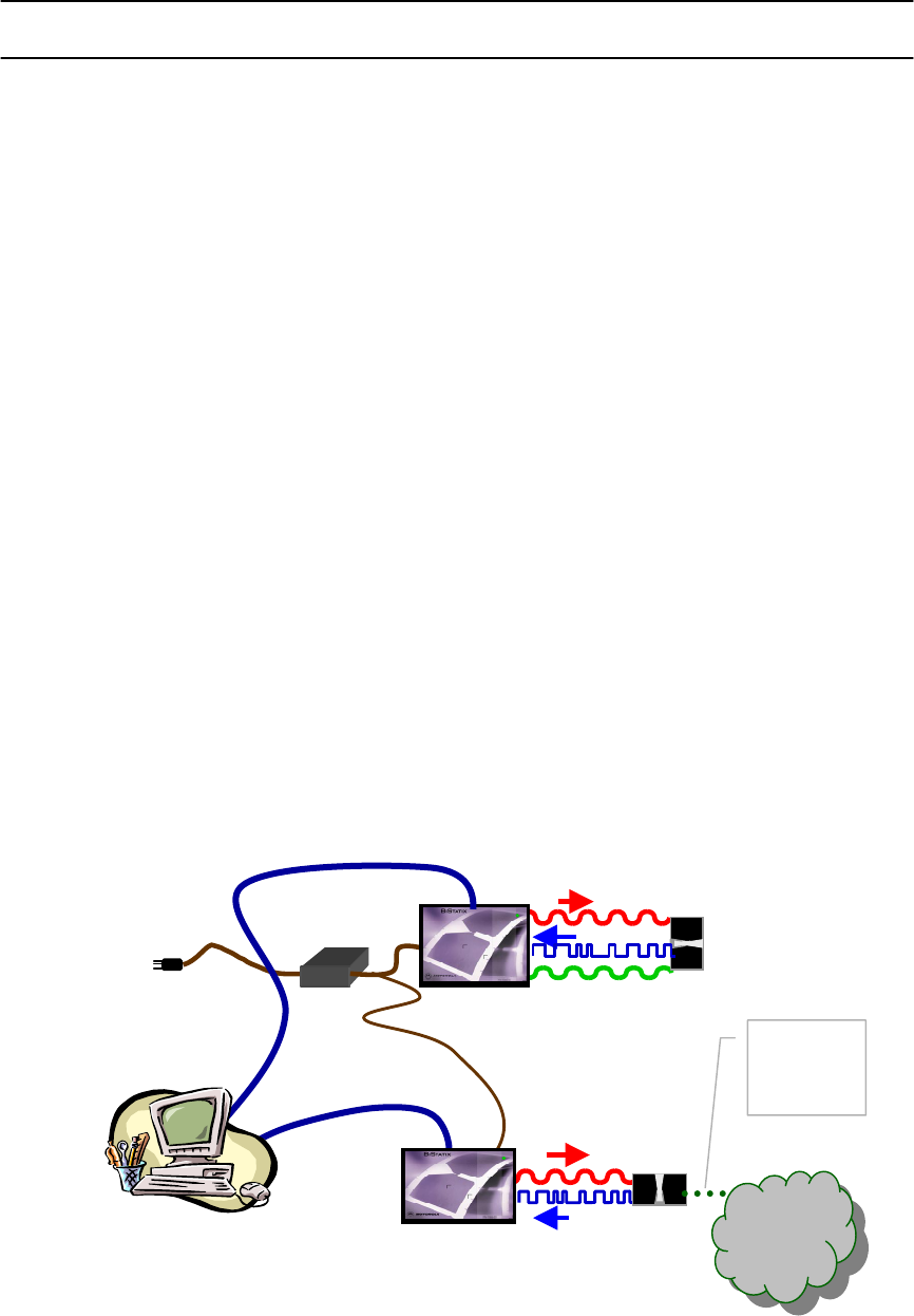
3 INSTALLATION & WIRING
3.1 Setup
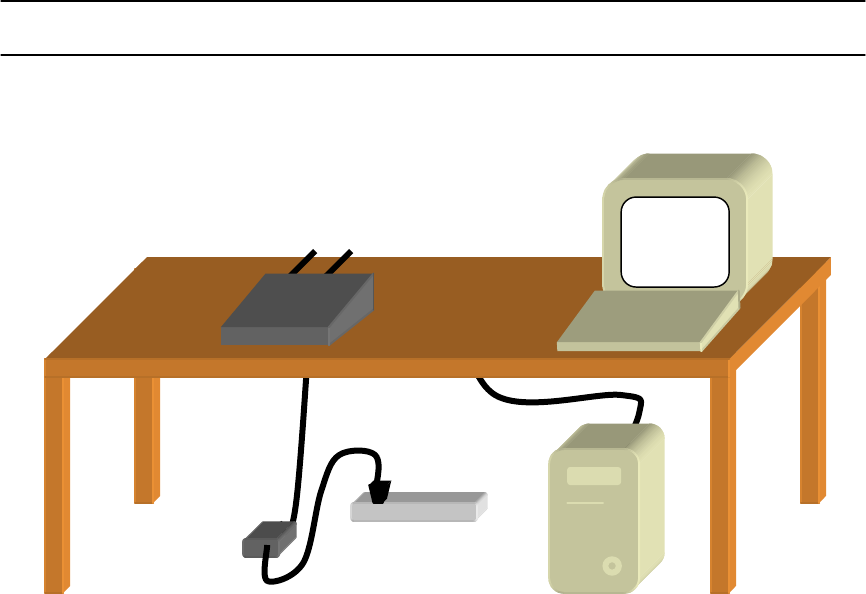
Figure 4 Hookup Diagram
• Figure 4 shows a typical installation of the BDR-1000.
• As shown the only connections to the BDR-1000 are the DC input from the power supply
and a serial communication cable (either RS-232, RS0422 or RS-485) from the host.
These connections are made at the enclosure rear panel. See BDR-1000 Rear Panel,
Figure 3 for a view of the rear panel.
• Because this technology is based on radio frequency signals nearby environmental
sources of electrical interference may affect the performance of the equipment. Below is
a list of precautions that should be considered when installing the equipment.
1. Keep the computer and monitor at least 1 meter away from the BDR-1000
enclosure.
2. Insure cable exiting from the rear panel is perpendicular to the rear edge of the
enclosure.
3. Insure that a non-metal table is used.
4. Metal affects radio signals. Keep any metallic objects clear (at least 1meter
away) of the enclosure.
5. Nearby external sources of electrical interference, such as sources of RF signal
transmitters (portable two-way radio, cellular phones, etc.) and/or nearby EMI
noise producers may contribute to disturbing the electrical environment of the
reader. Depending upon the external noise signal strength of the nearby
transmitter, the performance may be reduced or the tag signal may be masked
by the external signal, resulting in a non-operation.
May 4th, 2001 K01994-001 Rev 2 12
6. Maintain all equipment wiring a minimum distance of 30 cm (12 inches) away
from other wiring such as AC power, computer data wiring, telephone wiring or
wiring to electric locking devices, etc.
7. Do not install the equipment in areas where sources of broad spectrum EMI
noise may be present. Examples of EMI broad spectrum noise producers are
motors, pumps, generators, AC-DC converters, un-interruptible power supplies,
AC switching relays, light dimmers, computer monitors, and CRTs.
8. WARNING: Opening the sealed enclosure can expose you to high voltages. No
user serviceable parts inside.
3.2 Host Interface Wiring
Cable Size and Type
Maximum
Length
Manufactures P/N
RS-232 supplied 7.6 m (25 feet) Assmann xxxxx
RS-422 TBD Xxx m (xx feet) TBD
RS-485 TBD Xxx m (xx feet) TBD
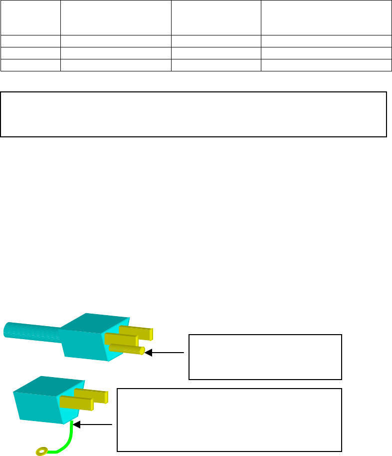
Figure 5 RS-485 Cable Assembly
3.3 Grounding Requirements
BiStatix Technology requires a RF ground when used in the MonoPole Mode to provide
a return path for the exciter current. The power supply that is used to operate the BDR-
1000 will provide this path as long as the required local ground is connected at the AC
source.
This ground can be either an earth ground or a local ground as required for the
particular application. In any event the ground connection should be made as shown
below.
Figure 6 AC Supply Grounding
Ensure that the ground of the
three terminal power cord is
connected to Earth ground.
If a three terminal receptacle is not available, a
three terminal to two terminal adapter may be used.
It is important that the ground lug on the
adapter is connected to Earth ground.
Drawing Showing construction of a RS-485 cable.
May 4th, 2001 K01994-001 Rev 2 13
4 OPERATION
4.1 Reader Operation
An on/off switch is provided on the rear panel to apply power to the BDR-1000. At power
up the BDR-1000 will perform a “BeepflashTM” and then place the LED in a “Solid Green”
state. At this time the BDR-1000 will read a properly programmed tag if it is presented.
The power up sequence also configures it to communicate with a host controller via
RS232 (see communication interfaces Section1).
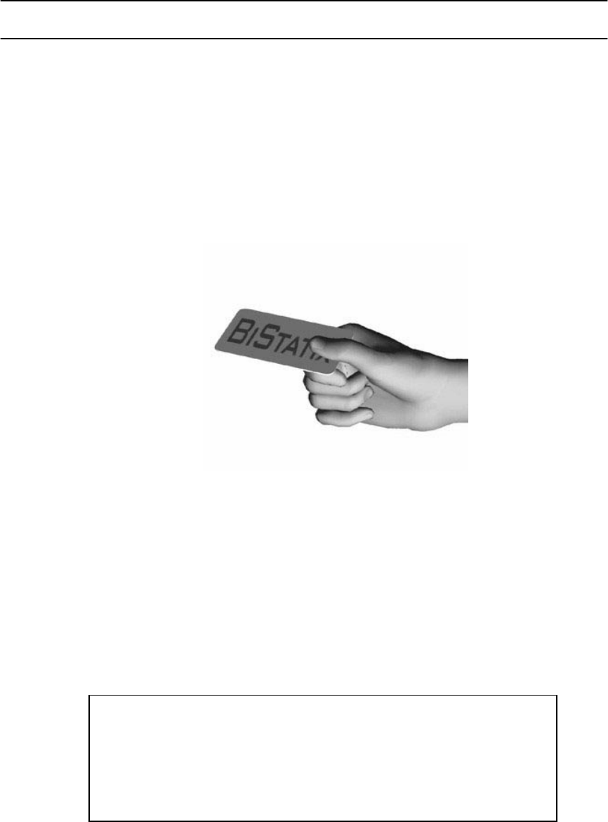
Figure 5 below demonstrates a monopole tag presentation (preferred method of reading
tags for the BDR-1000). Upon reading the tag an audible (beeper)and visual (LED Flash)
feedback is provided to verify that the tag has been read (see section 4.3 for details).
Figure 7 BiStatix Read Mode Monopole Tag Presentation
4.2 Programmer Operation
Commands from the Host Computer can configure the BDR-1000 to act as a Tag
Programmer and allow it to program tags or cards. Complete documentation and
Application Software for this mode is provided with either the BDK-1000 or the SDK-
1000. Refer to the installation manual provided on the CD that accompanies these
products for information. Figure 8 below demonstrates a DiPole tag presentation
(preferred method for the BDR-1000) to program the contents of a tag. Both audible and
visual indicators provide feedback to the user when the tag has been programmed and
confirmed (see section 4.3 for details).
Figure 8 BiStatix Program Mode Di-pole Tag Presentation
This diagram will show a typical Program Mode presentation in
the Di-Pole configuration. The tag will be placed upon the BDR-
1000 label in the correct position.

May 4th, 2001 K01994-001 Rev 2 14
4.3 Indicators
LED Color LED State Description
Green Solid Continuous Read Mode (default condition upon power up).
Two beeps upon power up.
Green Flashing Power on, reader functionality disabled. Will read upon Host
command.
Amber Solid Tag currently being read or programmed.
Single beep upon successful completion. LED returns to green
or green flashing.
Red Solid Programming failure, LED remains red until overridden by Host
command.
Beeps three times in succession.
Green / Red Alternating Power on self-test failure. Power cycling may clear problem.

May 4th, 2001 K01994-001 Rev 2 15
5 BDR-1000 CONFIGURATION PARAMETERS
The BDR-1000 Reader is designed for use with the BiStatix Developer Kit (BDK-1000). As such,
it comes configured for use with a PC (RS-232) and the software included in the BDK-1000. No
additional setup or configuration is required. Refer to the BDK-1000 Reference document on the
BiStatix Software Developer Kit CD-ROM for use in the developer configuration.
However, the BDR-1000 can also be used as a desktop reader or tag programmer. To use the
BDR-1000 Reader in other configurations its configuration parameters may need to be changed.
The BRUtil software is provided for purpose as well as verifying basic operation and
programming tags. It can be found either separate on the BRUtil CD-ROM or included in the
BiStatix Software Developer Kit CD-ROM. Refer to the BRUtil User’s Guide located on the
CD-ROM.
Listed below is a description of the BDR-1000 Configuration Parameters and their default settings
as configured at the factory. These parameters are set for use with the BiStatix Developer Kit.
Parameter Name Description BDR-1000
Default
Reader Address Reader address (1…255). 0 is reserved for the Host. 255
BaudRate Communication baud rate from 9600 bps to 36,400 bps: 9600 bps
IOType RS-232, RS-422 or RS-485 RS-232
ReadContEnable Read Continuous mode at startup. This mode continuously
searches for tags and notifies the host when one is found.
Optionally, it also sends the tag data with the notification. See
the TagDataSend parameter.
ON
TagDataSend When both ReadContEnable is ON and this option is ON the
tag data is returned with notification of a new tag found. If
either option is OFF then tag data is not returned.
ON
TagDataStart This option is applicable only if TagDataSend is ON. This
value defines the first offset of the tag to read and return to the
Host when a tag is found.
0
TagDataLength This option is applicable only if TagDataSend is ON. This
value defines the number of bytes on the tag to read and return
to the Host when a tag is found. A value of 255 indicates to
read all tag bytes.
255
WriteEnable When this option is ON the Reader is capable of writing tags.
When this option is OFF the Reader ignores write commands.
ON
TagExit When ON, this option instructs the Reader to notify the Host
when a tag exits the RF field.
OFF
NotifyAsync When ON, this option instructs the Reader to automatically send
notifications to the Host asynchronously.
ON
HostOpControl When ON, this option tells the Reader to the Host will control
the LED and beeper for all normal operation. When OFF the
Reader controls the LED and beeper.
OFF
HostPupControl When ON, the Host controls the power up operation of the LED
and beeper. When OFF the Reader controls the LED and
beeper on power up.
OFF
Retries Number of write retries (0…3). 0

May 4th, 2001 K01994-001 Rev 2 16
6 BDR1000 to BXR610 Compatibility
WARNING: Two different BiStatix RFID applications exist at this time. One is for Access Control
Applications and the other is for Industrial Applications. The BDR1000 is an Industrial BiStatix
RFID system. It utilizes a firmware package called Fiji which is different from the one used in
Access Control systems. The BXR610 is also BiStatix RFID system but the intent of this
application is for Access Control. The BXR610 uses an ACP tag for operation and will not
function properly with a Fiji tag. In the same manner the BDR1000 uses a Fiji tag for operation
and will not function properly with an ACP tag.
In either case when the incorrect tag is presented to these product the hardware will still perform
a BeepflashTM to acknowledge reading but the tag data will be misinterpreted and transmitted
incorrectly. The follow is an outline of the compatibility of the two systems.
Reading Tags
1. If presenting a ACP tag to a BDR1000 the output will be the UID field only.
2. If presenting a Fiji tag to a BXR610 the output is undefined at this time.
Programming Tags
1. If writing to an ACP tag with a BDR100 the tag will become a Fiji tag and will no
longer function with access control technology.

May 4th, 2001 K01994-001 Rev 2 17
7 TROUBLESHOOTING
WARNING: Opening the sealed unit can expose you to high voltages. No user serviceable parts
inside. If the reader does not function properly when installed according to instructions, please
complete this form and fax it to (408) 434-7057 before calling (800) 646-3252 for technical
assistance. International customers call (408)383-4000:
FAX
From:
To: Technical Support
Phone: Model: BDR-1000
Fax: Fax: (408) 434-7057
Product S/N Date:______________
Product Sales Order Number
Cannot Read Tags
1. Is the setup according to instructions? o Yes o No
2. Was read mode checked following a Power Cycle? o Yes o No
3. Is an earth ground connected according to instructions? o Yes o No
4. Is the supplied power supply being used? o Yes o No
5. At reader power up, did reader exhibit SelfTestTM? o Yes o No
6. Does both MonoPole and DiPole Read Mode Fail o Yes o No
7. Are the card presentations according to instructions o Yes o No
8. Upon card presentation, did reader exhibit QuickFlashTM? o Yes o No
Short Read Range
1. Is the setup according to instructions? o Yes o No
2. Is an earth ground connected according to instructions? o Yes o No
3. Is the supplied power supply being used? o Yes o No
4. Is there a CRT (computer monitor) nearby? o Yes o No feet
5. Is the Tag or Card presentation according to instructions? o Yes o No
Cannot Program Tags
1. Is BRUtil S/W being used? o Yes o No
2. Is an earth ground connected according to instructions? o Yes o No
3. Is the supplied power supply being used? o Yes o No
4. Does both MonoPole and DiPole Write Mode Fail? o Yes o No
4. Does the Read Mode function properly? o Yes o No
5. Is the Tag or Card presentation according to instructions? o Yes o No
Trouble Using the BRUtil Utility.
1. Has Serial Communication been established? o Yes o No
2. Do any Hardware Commands Function Properly? o Yes o No
3. Describe the Host Computer being used. .
May 4th, 2001 K01994-001 Rev 2 18
8 ADDITIONAL INFORMATION
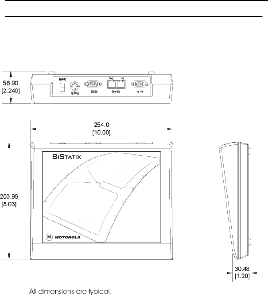
8.1 Mechanical Dimensions
Figure 9 BDR-1000 Mechanical Dimensions
May 4th, 2001 K01994-001 Rev 2 19
8.2 Copyrights Patents and Trademark Credits
© 1997 Motorola Corporation. reserves all rights including patents,
copyrights, trademarks, trade names, and all other intellectual property
rights worldwide. No reproduction, adaptation, or translation is allowed
without prior written permission from Motorola Corporation. Motorola
Corporation reserves the right to change any product description and/or
specification contained here without prior notice.
Patents pending worldwide.
8.3 Warranty
This product is guaranteed against defects in material and workmanship in
accordance with the Terms and Conditions of the Purchase Order
acknowledgement. In no event shall the BDR – 1000 warranty exceed one
year from the data of purchase.
8.4 RMA (Return Material Authorization)
Goods returned for repair, warranty or non-warranty, must be assigned an
RMA (Return Material Authorization) number. The customer is to provide a
description of the specific problem.
For readers returned and not covered by the warranty (due to age, misuse,
tampering and/or damage), a quote for repairs will be issued, and no work
will be performed until a valid purchase order is received. Readers left
over 30 days without a repair authorization and a purchase order will be
returned with evaluation charges and shipping costs applied.
8.5 Contacting Customer Support
Please answer all applicable questions in section 7.0 "Troubleshooting"
before contacting the Technical support number listed below:
U.S.A. Office:
3041 Orchard Parkway
San Jose, CA 95134-2017
Tel (408) 383-4000, Main
Tel (800) 646-3252, Technical Support
Fax (408) 434-7057
European Office
Jays Close
Viables Industrial Estate
Basingstoke
Hants RG22 4PD
UK
Tel: +44 1256 358211
Fax: +44 1256 488144

May 4th, 2001 K01994-001 Rev 2 20
Index
TBD