HID Global 6055BA HID MIFARE Reader User Manual Install Manual
HID Global Corporation HID MIFARE Reader Install Manual
Install Manual
SHEET: 1 of 5
SCALE: N/A
SIZE
ACAGE CODE DWG NUMBER
6055-910 REV
A
DWG DESCRIPTION
MANUAL, INSTALL,
IQ CARD READER
IRVINE, CALIFORNIA
DO NOT SCALE DRAWING
APPROVALS DATE
DRW: ANDRESKY
CHK:
APVD:
APVD:
11/29/00
MMDDYY
MMDDYY
MMDDYY
EXCEPT AS NOTED
DIM ARE IN INCHES
PER ANSI Y14.5
.XX .XXX ANGLES
+/-.01 +/-.005 +/-1°
MATERIAL:
FINISH:
REV STATUS
OF SHEETS SHEET
REV
12345678910 11 12 13 14 15 16 17 18 19 20 21 22 23 24
2222
SHEET
REV
25 26 27 28 29 30 31 32 33 34 35 36 37 38 39 40 41 42 43 44 45 46 47 48 49 50 51 52
REVISIONS
REV APPROVEDDATEDESCRIPTION
1
2
A
INITIAL PROTOTYPE RELEASE
Revised specs
INITIAL RELEASE

_____________________________________________________________________________________________________
HID Corporation 9292 Jeronimo Road Irvine, CA 92618-1905 USA TEL (949) 598-1600 (800) 237-7769 FAX (949) 598-1690
Web page, E-mail - www.hidcorp.com - IQ Card Reader Installation Manual 6055-910 Rev A Page 2 of 5
Install Manual – 6055-910 Rev 2
IQ Card Reader

_____________________________________________________________________________________________________
HID Corporation 9292 Jeronimo Road Irvine, CA 92618-1905 USA TEL (949) 598-1600 (800) 237-7769 FAX (949) 598-1690
Web page, E-mail - www.hidcorp.com - IQ Card Reader Installation Manual 6055-910 Rev A Page 3 of 5
PARTS LIST (Included)
Quantity
- IQ Card Reader with snap-on cover and 18” cable
1
- #6-32 x 1” self-tapping panhead screw
2
- Installation manual 1
PARTS LIST (Not-Included)
Quantity
- Wire splice 9
- DC Power supply 12 VDC1
1 Mounting Instructions
• Determine an appropriate mounting location. The
reader may be mounted to any surface, including
metal.
• Drill two (2) 3/32-inch (2.5mm) holes approximately
1 inch deep for mounting the reader.
• Drill a 5/8-inch (16mm) hole for the cable.
• Remove the snap-on cover from the reader and
secure the reader to the mounting surface.
• Route the cable from the reader and/or power
supply to the host. A linear type power supply is
recommended. Check all electrical codes for proper
cable installation.
• For the cable connection to the Panel - Use Alpha
#1299C or equivalent.
• Test the operation of the reader. After completion of
the test, replace the snap-on cover.
• See sheet 3 of this manual for the appropriate
dimensioned drawings.
• For proper regulatory compliance, the drain wire
should be disconnected at the power supply end of
the cable.
• Changes or modifications not expressly approved by
the party responsible for compliance could void the
user’s authority to operate the equipment.
• The Reader is intended to be powered from a
limited power source output of a previously certified
2 Connecting the Reader to the
Host
Connect the reader to the host according to the wiring
table below and the host installation guide.
Signal
Color
Signal
Color
9-14 VDC
Red
Beeper
Yellow
GND
Black
HOLD
Blue
D0
Green
CARD PRES
Violet
D1
White
RX
Pink
GRN LED
Orange
DTR
Gray
RED LED
Brown
TX
BLU/WHT
SHLD GND
Drain
3 Testing and Operation
• When power is applied to the reader the beeper
will beep once then the LED will flash green once

_____________________________________________________________________________________________________
HID Corporation 9292 Jeronimo Road Irvine, CA 92618-1905 USA TEL (949) 598-1600 (800) 237-7769 FAX (949) 598-1690
Web page, E-mail - www.hidcorp.com - IQ Card Reader Installation Manual 6055-910 Rev A Page 4 of 5
power supply.
• For installation in 15 EU countries, see addendum
(dwg #6055-911) for additional installation
instructions.
then red once.
• Present an ID card to the reader. The LED will
momentarily turn green while the beeper beeps once,
indicating that the card was read successfully.
Important Product Specifications
Power requirements (linear supply)
Operating Voltage Range 9.0 – 14.0 VDC
Absolute Maximum Voltage 16 VDC
Average Current at 12V 100 ma
Maximum cable distance 500 ft Wieg or C/D
To host 50 ft RS-232
FCC Compliance Statement: This device complies with
part 15 of the FCC rules. Operation is subject to the
following two conditions: (1) this device may not cause
harmful interference, and (2) this device must accept
any interference received, including interference that
may cause undesired operation.
_____________________________________________________________________________________________________
HID Corporation 9292 Jeronimo Road Irvine, CA 92618-1905 USA TEL (949) 598-1600 (800) 237-7769 FAX (949) 598-1690
Web page, E-mail - www.hidcorp.com - IQ Card Reader Installation Manual 6055-910 Rev A Page 5 of 5
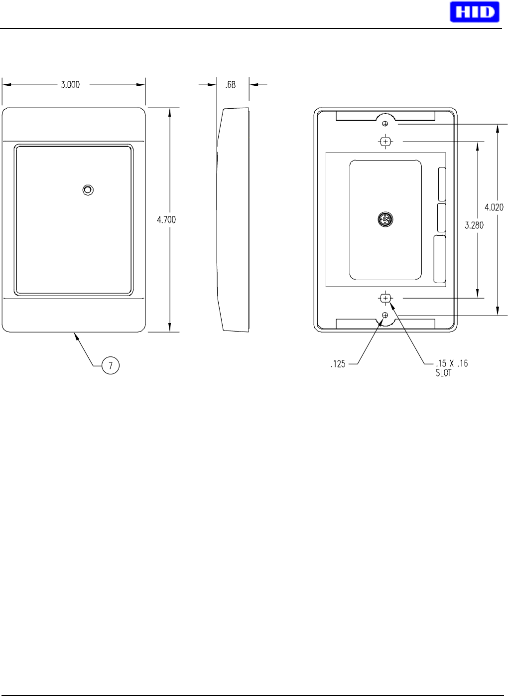
4 Front, side, and back view
4.1.1 Figure 1