HID Global 6055BC 6055C MIFARE Reader/Writer User Manual 6055 914 A 0
HID Global Corporation 6055C MIFARE Reader/Writer 6055 914 A 0
Users Manual

SHEET: 0 of 4 SCALE: N/A
SIZE
A CAGE CODE
DWG NUMBER
6055-914 REV
A.0
DWG DESCRIPTION
MANUAL, INSTALL,
HID MIFARE READER
IRVINE, CALIFORNIA
DO NOT SCALE DRAWING
APPROVALS DATE
DRW: ANDRESKY
CHK: C. SHEA
APVD: R. OKUDA
APVD: R. GREEN
11/29/00
062501
071401
071301
EXCEPT AS NOTED
DIM ARE IN INCHES
PER ANSI Y14.5
.XX .XXX ANGLES
+/-.01 +/-.005 +/-1
MATERIAL:
FINISH:
REV STATUS
OF SHEETS SHEET
REV
0 1 2 3 4 5 6 7 8 9 10 11 12 13 14 15 16 17 18 19 20 21 22 23
A A A A A
SHEET
REV
24 25 26 27 28 29 30 31 32 33 34 35 36 37 38 39 40 41 42 43 44 45 47 48 49 50 51 52
REVISIONS
REV APPROVED DATE DESCRIPTION
A
INITIAL RELEASE PER ECO ITG10324
.

_________________________________________________________________________________________________
HID Corporation 9292 Jeronimo Road Irvine, CA 92618-1905 USA TEL (949)598-1600 (800)237-7769
FAX (949)598-1690 Internet - www.hidcorp.com - HID Mifare Reader Installation Manual 6055-914 Rev A.0 Page 1 of 4
Install Manual – 6055-914 Rev A
6055C HID MIFARE Reader
_________________________________________________________________________________________________
HID Corporation 9292 Jeronimo Road Irvine, CA 92618-1905 USA TEL (949)598-1600 (800)237-7769
FAX (949)598-1690 Internet - www.hidcorp.com - HID Mifare Reader Installation Manual 6055-914 Rev A.0 Page 2 of 4
1 Parts List
PARTS LIST (Included) Quantity
- HID MIFARE Reader with snap-on
cover and 18in. 1
- #6-32 x 1” self-tapping panhead
screw 2
- Installation manual 1
PARTS LIST (Not-Included) Quantity
- Wire splice 9
- DC Power supply 12 VDC 1
2 Mounting Instructions
Determine an appropriate mounting location. The
reader may be mounted to any surface, including
metal.
Drill two (2) 3/32-inch (2.5mm) holes
approximately 1 inch deep for mounting the
reader.
Drill a 5/8-inch (16mm) hole for the cable.
A single-gang (2S) electrical junction box may
also be used; reader fits US hole pattern, and the
6-32 screws work with the J-box.
Remove the snap-on cover from the reader and
secure the reader to the mounting surface.
Route the cable from the reader and/or power
supply to the host. A linear type power supply is
recommended. Check all electrical codes for
proper cable installation.
For the cable connection to the panel - use Alpha
#1299C or equivalent.
Test the operation of the reader (Section 4). After
completion of the test, replace the snap-on cover.
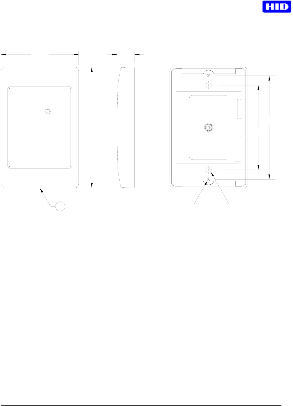
See Figure 1 for product and mounting
dimensions.
For proper regulatory compliance, the drain wire
should be disconnected at the power supply end
of the cable.
Changes or modifications not expressly approved
by the party responsible for compliance could
void the user’s authority to operate the
equipment.
The Reader is intended to be powered from a
limited power source output of a previously
certified power supply.
3 Connecting the Reader
Connect the reader to the host according to the
wiring table below and the host installation guide.
Signal Color DB9F DB25F
9-14 VDC Red - -
GND Black Pin 5 Pin 7
D0 Green - -
D1 White - -
GRN LED Orange - -
RED LED Brown - -
Beeper
HOLD
DSR
RX
DTR
TX
SHLD GND
Yellow
Blue
Violet
Pink
Gray
Tan
Drain
-
Pin 1
-
Pin 2
Pin 4
Pin 3
-
-
Pin 8
-
Pin 3
Pin 20
Pin 2
-
4 Testing and Operation
When power is applied to the reader the beeper
will beep and flash the LED green three times.
Present an ID card to the reader. The LED will
momentarily turn green while the beeper beeps
once, indicating that the card was read
successfully.
Please note that typical read range for MIFARE
cards is .75 to 1.5” (20 – 37 mm).
Important Product Specifications
Power supply
Absolute Maximum Voltage
Maximum Current at 12V
Operating Voltage Range
Linear type
16 VDC
94mA
9.0 – 14.0 VDC
Maximum cable distance
To host 50 ft RS-232
500 ft Wiegand
Operating temperature range -30 to 65C
FCC Compliance Statement: This device complies
with part 15 of the FCC rules. Operation is subject to
the following two conditions: (1) this device may not
cause harmful interference, and (2) this device must
accept any interference received, including
interference that may cause undesired operation.

_________________________________________________________________________________________________
HID Corporation 9292 Jeronimo Road Irvine, CA 92618-1905 USA TEL (949)598-1600 (800)237-7769
FAX (949)598-1690 Internet - www.hidcorp.com - HID Mifare Reader Installation Manual 6055-914 Rev A.0 Page 3 of 4
5 Card Compatibility
In the default configuration, the HID MIFARE
Reader reads HID-encoded OEM Card Data
(Wiegand data) from these cards:
HID MIFARE Card, Model 1430
HID MIFARE/Prox, Model 1431 (dual
technology)
Any Philips compatible MIFARE Standard
contactless smart card.
The HID MIFARE reader will not read 125 kHz
HID Proximity cards.
The reader will only output HID-encoded OEM
Wiegand data from cards encoded with matching
proprietary HID keys. Cards can either be
encoded at the factory, or by using an available
HID MIFARE Field Programmer.
The reader will read the MIFARE Card Serial
Number only from MIFARE Lite and MIFARE
Pro cards. These cards are not available with
Factory-encoded HID Card Data.
6 Reader Operation
There are two basic modes of reader operation:
Security Mode (the default mode) and
Transaction Mode.
Security Mode
Security Mode is for use in Access Control and
parking applications. In security mode, the reader
looks for two types of data on the card:
HID Factory encoded OEM format card data
Mifare Card Serial Number (CSN)
The reader may be configured in one of the
following Card Read Modes:
HID Card Data Only (default mode)
Mifare CSN Only
HID Card Data first, then look for CSN
In HID-Only Mode, when a card is presented, the
HID MIFARE Reader will look for HID-Encoded
OEM card data in Sector 1 as well as the
MIFARE Application Directory. Data is output in
standard Wiegand format, exactly as it is encoded
on the Mifare card, and it is also output on the
serial port. The reader can also be field-
configured to look for HID-encoded OEM card
data in a specific sector other than Sector 1.
In CSN Only mode, the reader reads the 32-bit
MIFARE random card serial number (CSN or
UID) from any MIFARE card, including
MIFARE Lite, MIFARE Standard and
MIFARE Pro, outputting that data in a Wiegand
format. MIFARE CSN Data is output via the
Wiegand port per the reader’s configuration to
one of the following CSN Output Modes:
32-bit Philips standard, MSB first (default)
32-bit Reverse Order (6055A compatible)
26-bit format (32-bit, truncated to 16 LSB, 8-
bit FC defaulted to 1, B/E parity) - FC may be
user-configured)
34-bit, Philips Standard + B/E parity
40-bit format - 32-bit CSN + 8 bit checksum
In HID+CSN mode, the reader first checks all
possible locations for HID OEM data, and if no
HID data is found, it outputs the CSN.
Card Read Mode and CSN Output Mode can be
ordered pre-configured at the factory, or may be
field-configured with Command Cards.
Consult HID Technical Support for information on
obtaining Command cards or for additional details
on configuration options.
Transaction Mode
The reader can also communicate via the serial
port for non-access control applications, including
read-write capability. When in transaction mode,
the reader asserts the DTR line to alert the Host
that a card ID is outputting, and it will continue to
output repeatedly until acknowledged by the host
controller. Configuration to Transaction Mode is
accomplished by a command from the Host via
the serial port. No command card is required,
and no special factory configuration is required.
A Software Development Kit is available – please
contact your dealer for details.
_________________________________________________________________________________________________
HID Corporation 9292 Jeronimo Road Irvine, CA 92618-1905 USA TEL (949)598-1600 (800)237-7769
FAX (949)598-1690 Internet - www.hidcorp.com - HID Mifare Reader Installation Manual 6055-914 Rev A.0 Page 4 of 4
3.000
4.700
.68
7
3.280
4
.02
0
.15 X .16
SLOT
.125
Figure 1 Front, Side and Back Views