HID Global 612XA 6125A multiCLASS RP40 User Manual
HID Global Corporation 6125A multiCLASS RP40 Users Manual
Users Manual
RW100, RW300, RW400 HSI Expansion Modules
HSI ModuleS connect to terMInal readerS (3122 - rS232, 3123 - rS485, 3124 - uSB)
InStallatIon
InStalacIón
InStallatIon
InStalação
InStallatIon
InStallazIone
HID Corporation
9292 Jeronimo Road
Irvine, California
92618-1905 USA
tel:
+1 (949) 598-1600
U.S. (800) 237-7769
fax:
+1 (949) 598-1690
email:
tech@hidcorp.com
www.hidcorp.com
6300-900 Rev A.0
Patent Pending For This Product
R10 • R30 • R40 • RP40 • RW100 • RW300 • RW400
partS
• 1 - iCLASS Reader
• 1 - Installation Manual
• 2 - 3.5 mm x .6 pitch x 12 mm
Phillips machine screws
• 3 - #6-32 x .375” Phillips
self-tapping machine
screws
• 2 - #6 x 1.5” Phillips sheet
metal screws
• 1 - #6 x .375” Spanner
security screw, anti-tamper
Recommended
• Up to 9 wire splices (pigtail)
• Cable, 5-9 conductor
(Wieg. or RS232), 22 AWG
shielded (pigtail)
• Linear DC Power supply
• Metal or plastic junction box
• Security Tool (for anti-
tamper screw) HID 04-0001-03
coMponenteS
• 1 lector
• 1 manual de instalación
• 2 Tornillos Phillips de 3.5mm
x 12mm, paso 0.6
• 3 Tornillos autoperforantes
N.° 6 para metales Phillips
32 x 0.375"
• 1 Tornillo de seguridad
N.° contra sabotaje 0.375"
Recomendado
• 9 empalmes para cable
• 1 cable, 5-9 conductores
(Wiegand o Rs-232) blin-
dado 22AWG
• Fuente de alimentación
lineal CC
• Caja de conexiones
metálica o de plástico
• Interruptor magnético,
Ademco 945T, Sentrol
1038T, GRI 100T, GRI 110T o
Aleph DC-2531
• Herramienta de seguridad
(para tornillo contra
sabotaje) HID 04-0001-03
pIèceS
• 1 lecteur
• 1 notice d'installation
• Vis mécaniques Phillips 2
3,5 mm x 0,66 (pas) x 12
• 3Vis mécaniques Phillips
autotaraudeuses #6-32 x
0,375"
• 1vis de sécurité anti-intru-
sion à tête carrée #6 x
0,375"
Recommandés
• 9 flûtes de jonction de fil
• 1 câble, 5-9 conducteurs
(Wiegand ou RS-232),
calibre 22AWG, blindé
• Alimentation c.c. linéaire
• Boîtier de jonction métal-
lique ou plastique
• Contact d'autoprotection:
Ademco 945T, Sentrol
1038T, GRI 100T ou 110T ou
Aleph DC-2531
• Outil de sécurité (pour vis
anti-intrusion) HID 04-
0001-03
peçaS
• 1 leitora
• 1 manual de instalação
• 2 parafusos Phillips para
aplicação à máquina de
3,5 mm x 0,6 de passo x 12
mm
• 3 parafusos Phillips no 6 de
auto-rosqueamento para
aplicação à máquina de
32 x 0,375 pol.
• 1 parafuso de segurança
de pino no 6 x 0,375 pol.,
anti-violação
Recomenda-se
• 9 emendas de fio
• 1 cabo, condutor 5-9,
(Wiegand ou RS232),
22AWG revestido
• Fonte de energia CD lin-
ear
• Caixa de junção metálica
ou plástica
• Interruptor magnético
– Ademco 945T, Sentrol
1038T, GRI 100T ou 110T, ou
Aleph DC2531
• Ferramenta de segurança
(para o parafuso anti-vio-
lação) HID 04-0001-03
teIle
• 1 Lesegerät
• 1 Installationshandbuch
• 2 3,5 mm x 12 mm
Sechskantschraube
(Gewindesteigung 6)
• 3 32 x 0,375" Sechskant-
schneidschraube Nr. 6
• 1 0,375" Sechskant-
sicherheitsschraube,
Sabotage-Schutz
Empfohlen
• 9 Kabelverbinder
• 1 Kabel, 5-9 Leiter
(Wiegand oder RS-232),
22 AWG geschirmt
• Lineare Gleichstromver-
sorgung
• Kabelkasten aus Metall
oder Plastik
• Magnetschalter, Ademco
945T, Sentrol 1038T, GRI
100T oder 110T oder Aleph
Dc-2531
• Sicherheitswerkzeug (für
die Sabotage-Schutz-
schraube) HID 04-0001-03
coMponentI
• 1 lettore
• 1 manuale di installazione
• 2 viti da macchina Philips
3,5 mm x passo 0,6 x
12 mm
• 3 viti da macchina auto-
filettanti Philips numero
6-32 x 0,375 pollici
• 1 vite di sicurezza a prova
di manomissione Spanner
numero 6-32 x 0,375 pollici
Consigliati
• 9 giunti conduttore
• 1 cavo, 5-9 conduttore
(Wiegand o RS-232),
schermato 22 AWG
• Alimentatore lineare c.c.
• Scatola di giunzione
metallica o in plastica
• Interruttore magnetico
Ademco 945T, Sentrol
1038T, GRI 100T o Aleph
DC-2531
• Utensile sicurezza (per vite
a prova di manomissione)
HID 04-0001-03
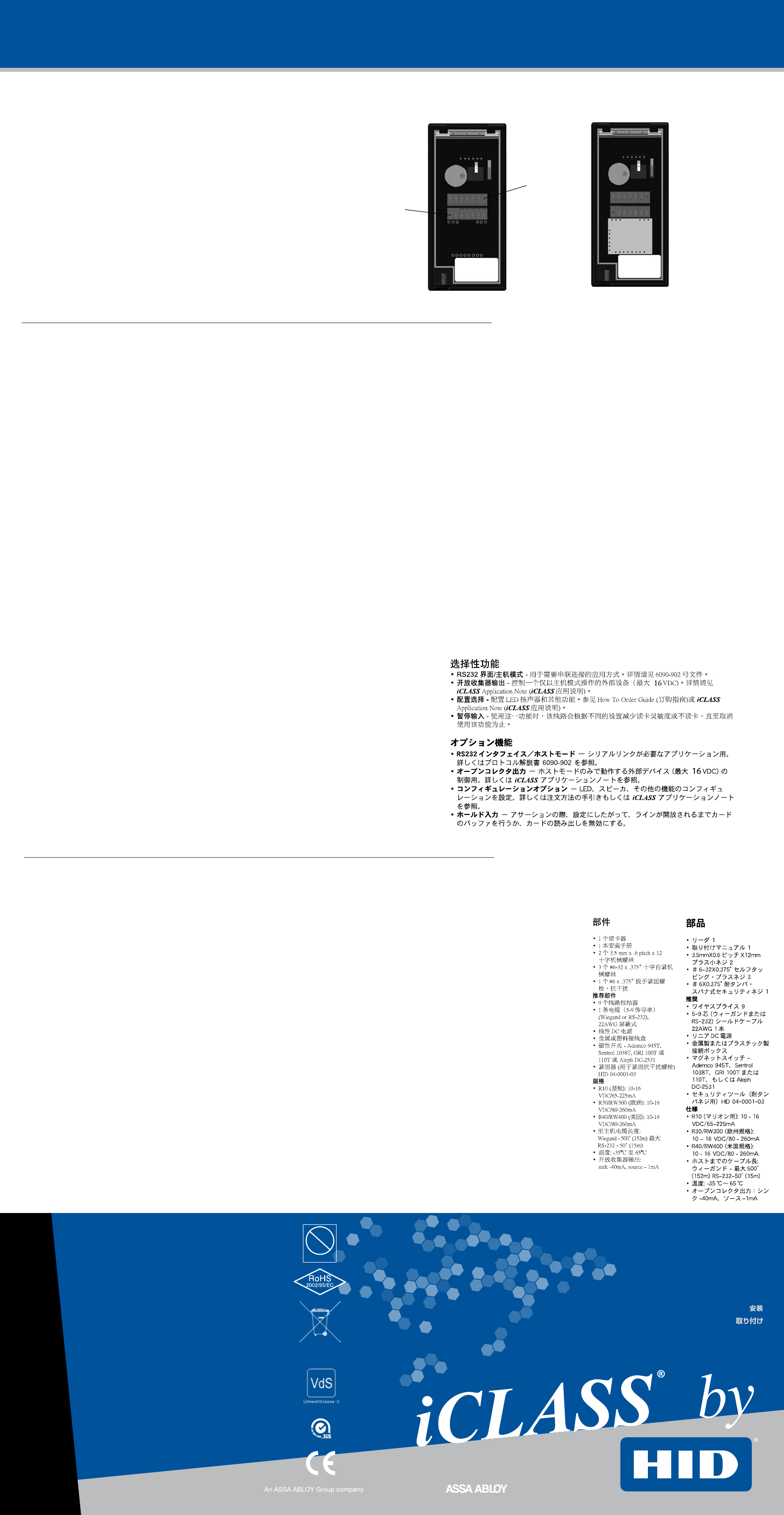
OPTIONAL FEATURES
4
Fcc warnIng
This device complies with part 15 of the FCC rules.
Operation is subject to the following two conditions:
(1) This device may not cause harmful interference.
(2) This device must accept any interference that may cause undesired operation.
• For proper regulatory compliance, the drain wire should be disconnected at the power supply end of the cable.
• Changes or modifications not expressly approved by the party responsible for compliance could void the user's authority
to operate the equipment.
• The Reader is intended to be powered from a limited power source output of a previously certified power supply.
caracteríStIcaS opcIonaleS
• HSI modules are available which plug into all terminal readers to provide optional functionality.
3122 - RS232, 3123 - RS485, 3124 - USB.
• Salida a colector abierto – Controla un dispositivo externo (16 VCC Máx.) operando en Modo
Host solamente. Para mayor información, consulte la Nota de Aplicación de iCLASS.
• Opciones de configuración – Permite configurar el Led, altavoz y otras características. Para
más detalles, consulte la Guía Cómo Hacer su Pedido o la Nota de Aplicación de iCLASS.
• Entrada de retención – Según sea la configuración, cuando esta línea se activa, se almacena
el valor de la última tarjeta leída o se deshabilita la lectura. Esto sucederá mientras esta línea
permanezca activada.
caractérIStIqueS optIonnelleS
• HSI modules are available which plug into all terminal readers to provide optional functionality.
3122 - RS232, 3123 - RS485, 3124 - USB.
• Sortie auxiliaire : peut être pilotée via la liaison série. Cf la note d'application iCLASS N° 28
• Configurations optionnelles : fonctionnement des LED, du Beeper, et autres fonctionnalités. Cf le
guide de commande pour plus de détails
• Entrée Hold : permet, si utilisée, de mémoriser une carte ou de désactiver la lecture de cartes
selon la configuration choisie.
recurSoS opcIonaIS
• HSI modules are available which plug into all terminal readers to provide optional
functionality.
3122 - RS232, 3123 - RS485, 3124 - USB.
• Tomada aberta de captação – controla um dispositivo externo (máximo de 16
VDC) em
operação exclusivamente no modo host. Para obter maiores detalhes, consulte a
observação de aplicação do iCLASS.
• Opções de configuração – configura o LED, o alto-falante e os outros recursos.
Para obter maiores detalhes, consulte o guia "Como fazer seu pedido" ou a
observação de aplicação do iCLASS.
• Bloqueio de entrada de sinal – quando ativada, esta linha impede a utilização
do cartão lido, ou desativa o cartão lido, até o momento em que for liberado,
de acordo com a configuração.
optIonale FunktIonen
• HSI modules are available which plug into all terminal readers to provide optional
functionality.
3122 - RS232, 3123 - RS485, 3124 - USB.
• Offener Kollektorausgang – steuert ein externes Gerät (16 V max.), das
nur im Hostmodus betrieben wird. Nähere Informationen unter iCLASS
Anwendungshinweis.
• Konfigurationsoptionen – LED, Lautsprecher und anderes konfigurieren. Nähere
Informationen unter Auftragsleitfaden oder iCLASS Anwendungshinweis.
• Halteeingang – wenn aktiviert, puffert diese Leitung entweder eine Karte oder
deaktiviert eine Kartenlesung bis zur Freigabe, je nach Konfiguration.
FunzIonI opzIonalI
• HSI modules are available which plug into all terminal readers to provide optional
functionality.
3122 - RS232, 3123 - RS485, 3124 - USB.
• Uscita collettore aperto - controlla un dispositivo esterno (mass. 16 V c.c.) che fun-
ziona solo in modalità host. Per dettagli, vedere la nota applicativa iCLASS.
•
Opzioni di configurazione - per configurare il LED, lo speaker e altre funzioni. Per
dettagli, vedere la guida alle ordinazioni o la nota applicativa iCLASS.
• Ingresso trattenuta - quando viene attivata, questa linea mette in buffer una
scheda o disabilita una scheda, secondo la configurazione.
• HSI modules are available which plug into all terminal readers to provide optional functionality.
3122 - RS232, 3123 - RS485, 3124 - USB.
• Open Collector Output - controls an external device (16 VDC Max) operating in Host Mode
only. See iCLASS Application Note for details.
• Configuration Options - Configure LED, Speaker, keypad operation, keypad lighting, and other
features. See How To Order Guide or iCLASS Application Note for details.
• Hold Input - when asserted, this line either buffers a card or disables a card read until released,
as configured.
PARTS
5
IP55
6
P1-1
P2-1
Pb
Pb-free
eSpañol Diagrama de cableado
Amarillo
Naranja
Negro
Rojo
Malla
Marrón
Azul
Verde
Blanco
Violeta
FrançaIS Schéma de câblage
portuguêS Diagrama de ligações
deutScH Schaltplan
InStallatIon
InStalacIón
InStallatIon
InStalação
InStallatIon
InStallazIone
1
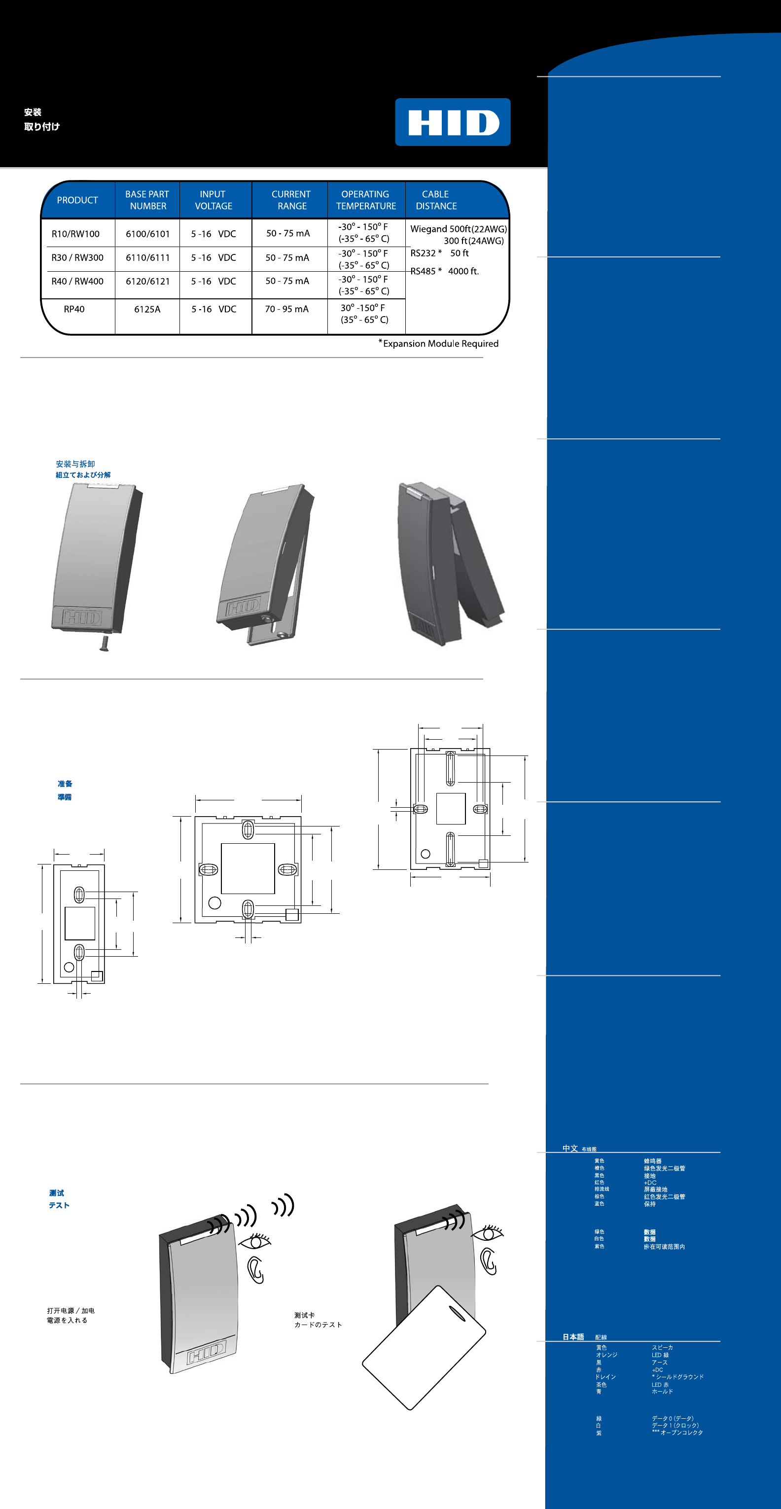
3teStIng
prueBa
teSt
teSte
teSten
teStare
Turn power on
Encienda la unidad
Mettez sous tension
Ligar energia
Strom einschalten
Accendere
Test card
Pruebe la tarjeta
Testez avec une carte
Placa de teste
Kartentest
Test
ItalIano Schema di collegamento
1.63”
4.14 cm
3.75”
9.53 cm 1.60”
4.06 cm 2.04”
5.18 cm
2.99”
7.59 cm
2.99”
7.59 cm
.156”
.40 cm
2.00”
5.08 cm 2.44”
6.20 cm
.156”
.40 cm
.156”
.40 cm
2.99”
7.59 cm
2.00”
5.08 cm
2.00”
5.08 cm
2.44”
6.20 cm
4.00”
10.16 cm
4.49”
11.40 cm
R10
RW100
R30/RW300
R40/RW400
iCLASS® by
®
2
aSSeMBly and dISaSSeMBly
Montaje y deSMontaje
Montage et déMontage
MontageM e deSMontageM
zuSaMMenBau und zerlegung
MontaggIo e SMontaggIo
preparIng
preparacIón
préparatIon
preparação
vorBereItung
preparazIone
* Drain wire can be “data return” line when a separate power supply is
used
** Requires Expansion Module [ RS232, RS485, USB ]
*** Tamper Output
(See section 4 for terminal connections)
P1-1
P1-2
P1-3
P1-4
P1-5
P1-6
P1-7
P2-1
P2-2
P2-3
P2-4
P2-5
P2-6
P2-7
Beeper Input
Green LED
Ground
VDD
*Shield Ground
Red LED
Hold
**Expansion module
**Expansion module
Wiegand Data 0
Wiegand Data 1
***Open Collector Output
**Expansion module
**Expansion module
englISH Wiring diagram
Yellow
Orange
Black
Red
Drain
Brown
Blue
Green
White
Violet
altavoz
Led verde
Tierra
+CC
*blindaje de tierra
Led rojo
entrada de retención
**Expansion Module
**Expansion Module
Dato 0 (datos)
Dato 1 (reloj)
***salida a colector abierto
**Expansion Module
**Expansion Module
P1-1
P1-2
P1-3
P1-4
P1-5
P1-6
P1-7
P2-1
P2-2
P2-3
P2-4
P2-5
P2-6
P2-7
* Drain wire can be “data return” line when a separate power supply is
used
** Requires Expansion Module [ RS232, RS485, USB ]
*** Tamper Output
(See section 4 for terminal connections)
Jaune
Orange
Noir
Rouge
Drain
Brun
Bleu
Vert
Blanc
Violet
Beeper
LED verte
Masse
+DC
*Masse blindage
LED rouge
Hold
**Expansion Module
**Expansion Module
Données 0
Données 1
***Sortie auxiliaire
**Expansion Module
**Expansion Module
P1-1
P1-2
P1-3
P1-4
P1-5
P1-6
P1-7
P2-1
P2-2
P2-3
P2-4
P2-5
P2-6
P2-7
* Drain wire can be “data return” line when a separate power supply is
used
** Requires Expansion Module [ RS232, RS485, USB ]
*** Tamper Output
(See section 4 for terminal connections)
amarelo
laranja
preto
vermelho
dreno
marrom
azul
verde
branco
violeta
bíper
LED verde
terra
CA+
*terra do gabinete
LED vermelho
reserva
**Expansion Module
**Expansion Module
Dados 0 (dados)
Dados 1 (clock)
***(placa presente)
**Expansion Module
**Expansion Module
P1-1
P1-2
P1-3
P1-4
P1-5
P1-6
P1-7
P2-1
P2-2
P2-3
P2-4
P2-5
P2-6
P2-7
* Drain wire can be “data return” line when a separate power supply is
used
** Requires Expansion Module [ RS232, RS485, USB ]
*** Tamper Output
(See section 4 for terminal connections)
Gelb
Orange
Schwarz
Rot
Drain
Braun
Blau
Grün
Weiss
Violett
Signal
Grüne LED
Erde
+Gleichstrom
*Schirmerde
Rote LED
Halten
**Expansion Module
**Expansion Module
Daten 0 (Daten)
Daten 1 (Zeit)
***(Karte vorhanden)
**Expansion Module
**Expansion Module
P1-1
P1-2
P1-3
P1-4
P1-5
P1-6
P1-7
P2-1
P2-2
P2-3
P2-4
P2-5
P2-6
P2-7
* Drain wire can be “data return” line when a separate power supply is
used
** Requires Expansion Module [ RS232, RS485, USB ]
*** Tamper Output
(See section 4 for terminal connections)
giallo
arancione
nero
rosa
cavo di terra
marrone
blu
verde
bianco
viola
Ronzatore
Led verde
terra
TX (trasmissione seriale)
*Schermo di terra
Led rosso
Memoria
**Expansion Module
**Expansion Module
Dato 0 (dato)
Dato 1 (clock)
***(scheda attiva)
**Expansion Module
**Expansion Module
P1-1
P1-2
P1-3
P1-4
P1-5
P1-6
P1-7
P2-1
P2-2
P2-3
P2-4
P2-5
P2-6
P2-7
* Drain wire can be “data return” line when a separate power supply is
used
** Requires Expansion Module [ RS232, RS485, USB ]
*** Tamper Output
(See section 4 for terminal connections)
P1-1
P1-2
P1-3
P1-4
P1-5
P1-6
P1-7
P2-1
P2-2
P2-3
P2-4
P2-5
P2-6
P2-7
**Expansion Module
**Expansion Module
**Expansion Module
**Expansion Module
***
*
* Drain wire can be “data return” line when a separate power supply is
used
** Requires Expansion Module [ RS232, RS485, USB ]
*** Tamper Output
(See section 4 for terminal connections)
P1-1
P1-2
P1-3
P1-4
P1-5
P1-6
P1-7
P2-1
P2-2
P2-3
P2-4
P2-5
P2-6
P2-7
**Expansion Module
**Expansion Module
**Expansion Module
**Expansion Module
* Drain wire can be “data return” line when a separate power supply is
used
** Requires Expansion Module [ RS232, RS485, USB ]
*** Tamper Output
(See section 4 for terminal connections)