HID Global ASR620PLUSPLUS ASR-620++ Long Range Reader User Manual K02021 000 Rev A
HID Global Corporation ASR-620++ Long Range Reader K02021 000 Rev A
Contents
- 1. Users Manual 1
- 2. Users Manual 2
Users Manual 1

K02021-000 Rev A April 2006
FlexPass TM
Advantage Series Proximity Plus TM
ASR-620++ PowerProx TM Reader
User Manual
K02021-000 Rev A April 2006
ii
FCC Compliance: This equipment has been tested and found to comply with the limits for a Class B digital device,
pursuant to Part 15 of the FCC rules. These limits are designed to provide reasonable protection against harmful
interference in a residential installation. This equipment generates, uses and can radiate radio frequency energy and,
if not installed and used in accordance with the instructions, may cause harmful interference to radio
communications. However, there is no guarantee that interference will not occur in a particular installation. If this
equipment does cause harmful interference to radio or television reception, which can be determined by turning the
equipment off and on, the user is encouraged to try to correct the interference by one or more of the following
measures:
• Reorient or relocate the receiving antenna.
• Increase the separation between the equipment and the receiver.
• Connect the equipment into an outlet on a circuit different from that to which the receiver is
connected.
• Consult the dealer or an experienced radio/TV technician for help.
UL Listing: The ASR-620++ has been evaluated by UL to UL-294 standard and is listed under file
BP6430.
CE Compliance: This product complies with the European Community Council Directive
89/336/EEC and the standards specified under IETS-300-683 and IETS-300-330, if the installer/ user
adheres to the instructions detailed in this manual.
Notice: The ASR-620++ reader requires the use of linear, series pass power supplies. Switching power
supplies are not recommended because the use of these supplies may reduce the read range.
The unit is intended to be powered from a current limited power source such as an IEC/EN 60950
approved power supply.
Do not use the reader’s power supply for other equipment, particularly when operating switched inductive
loads such as motor control relays and solenoids (i.e., magnetic locks, latch or strike). Doing so will affect
the reader operation. Use a separate dedicated power supply for Indala proximity readers.
Because this technology is based on radio frequency and because nearby environmental sources of
electrical interference may affect the performance of the reader, the following is a list of precautions that
should be considered when installing or wiring the reader:
• Metal affects radio signals. Do not cover the face of the reader with metal of any kind.
• Reduce or eliminate unwanted signals from external sources.
• Do not place the reader wiring bundled in conduit with AC power cables, lock power or signal
wiring.
K02021-000 Rev A April 2006
iii
• Maintain all reader wiring a minimum distance of 12" (30 cm) away from other wiring such as
AC power, computer data wiring, telephone wiring or wiring to electric locking devices, etc.
• Do not install the reader in areas where sources of broad spectrum EMI noise may be present.
Examples of EMI broad spectrum noise producers are motors, pumps, generators, AC-DC
converters, uninterruptable power supplies, AC switching relays, light dimmers, computer
monitors and CRTs.
K02021-000 Rev A April 2006
iv
K02021-000 Rev A April 2006
1
1.0 Overview
1.1 Introduction
The ASR-620++ reader is a rugged radio frequency reader designed for applications such as identification
systems, security systems and data collection. The ASR-620++ reader mounts on most flat surfaces. The
reader electronics are enclosed with a gasket sealed cover to provide weather resistance.
The reader outputs data in Wiegand or ABA Track II (Mag Stripe) format. An optional RS-232 interface
requires the use of a BIL-422/232 Signal Conditioning Module which is sold separately.
1.2 Features
• QuickFlashTM for immediate user feedback.
• SelfTestTM for installer assistance during installation.
• WatchDogTM for increased supervisory control.
• Independently controlled audio tone and tri-color status LEDs.
• Field programmability via ProxSmithTM software toolkit (available separately) and option cards.
• Mounting on most flat surfaces.
• Indoor/outdoor operation.
• Attractive, contemporary styling.

K02021-000 Rev A April 2006
2
1.3 Specifications
• Input Voltage: 12.0 VDC to 24 VDC.
• Input Current/Power
-Typical, quiescent off metal Vin = 12.0 VDC 1.0 A 12 W
Vin = 24.0 VDC 750 mA 18.0 W
-Maximum, quiescent off metal Vin = 12.0 VDC 1.2 A 14.4 W
Vin = 24.0 VDC 920 mA 22.1 W
-Maximum Power 12.0 VDC ≤ Vin ≤ 24.0 VDC 22.1 W
• Recommended Power Supply: Regulated linear power supply
12 VDC at 1.5 A (per reader)
24 VDC at 1.0 A (per reader)
• Read Range with the Indala
FlexCardTM Card Up to 28.0” (71.7 cm)
• Operating Temperature Range: -35°C to +65° C (-31°F to +149°F)(See Note 2.)
• Color: Black
• Material: UV resistant, ABS /polycarbonate (UL94V0) plastic.
• Weight (Typical): 3.2 lbs (1.45 kg)
• Dimensions: 11.2” H x 11.2” W x 1.8 “T (28.4 x 28.4 x 4.6 cm)
• Output Formats: Wiegand, ABA track2 Magnetic Stripe. (Contact Factory for
other formats.
• Certification UL-294 indoor and outdoor compliant, CE Mark, and FCC
Class B Digital Device (Part 15) ID Numbers E9U620.
Note 1 Read Range is stated in an undisturbed electrical environment, with card presented
parallel to reader, and reader installed in accordance with Indala instructions. The power
supply, reader and controller must be on the same ground, connected to earth.
Note 2. At temperatures below -20ºC the beeper output may not be audible, except at short
distances.
Note 3. The ASR620++ reader is tuned for mounting on non-ferrous surfaces. If the reader must
be mounted on, or near, a ferrous surface a minimum 3 inch (7.6cm) non-ferrous spacer
must be used.
Note 4. There is no longer a need for the CT-620 power conditioner with the ASR-620++. The
CT-620 was necessary in earlier versions of the ASR-620 to meet European emmissions
standards, but is not needed with the ASR-620++.
K02021-000 Rev A April 2006
3
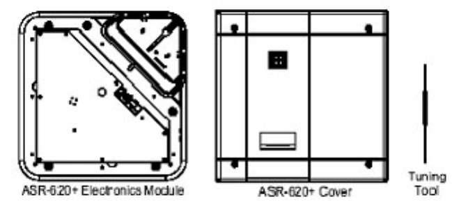
1.4 Unpacking and Identifying Supplied Parts
Unpack the equipment and become familiar with the components (see Figure 2, ). The ASR-620++ package contains the ASR-
620++ reader electronics module, the ASR-620++ cover, and a tuning tool.
Figure2a ASR-620++++ Package Contents
Figure 1. ASR-620++ Reader and Cover
K02021-000 Rev A April 2006
4
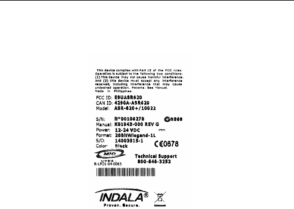
1.5 Identifying the Reader Format
The reader format is printed on the ID label (see figure 3) located on the rear of the base assembly, and
under the cover on one of the two metal shields.
Figure 3. The Reader Label
K02021-000 Rev A April 2006
5
2.0 Installation
2.1 Mechanical Installation
Proper operation of the reader requires mounting it on a vertical surface with the LEDs located in the top
left corner.
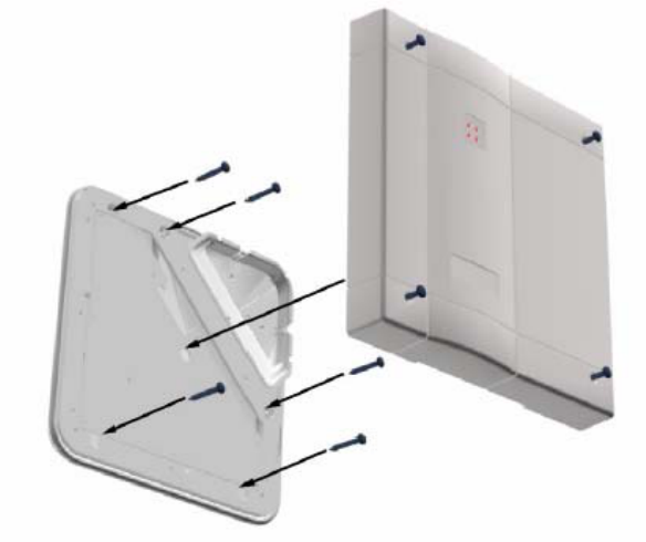
2.1.1 Wall Mounting
Figure 3. Wall mounting the ASR-620++ reader
Drill the mounting holes to a #8 clearance and drill the cable hole to at least 13/16” (0.813”) diameter.
Remove the cover from the base and feed the cable through the cable clearance hole. Attach the reader to
the wall using #8 screws. Insure the O-rings are installed between the mounting screw heads and the base
housing (do not over tighten the screws). Route the reader cable to the controller. For mechanical
dimensions, cable and hole location of the ASR-620++, refer to Section 5.1 (Mechanical Drawings, page
15).
NOTE: The ASR620++ reader is tuned for mounting on non-ferrous surfaces. If the reader must
be mounted on, or near, a ferrous surface a minimum 3 inch (7.6cm) non-ferrous spacer
must be used.

K02021-000 Rev A April 2006
6
2.1.1 Power Supply Cable Types and Recommended Lengths
The ASR-620++ reader requires a minimum voltage of 12.0 VDC at the reader. Voltage drops, caused by
the cable resistance, can be made up by increasing the power supply voltage. DO NOT SET THE
POWER SUPPLY VOLTAGE TO HIGHER THAN 28 VDC! In noisy environments, use shorter
cable runs. The data in Table 1, shows the recommended cable types and cable lengths for cables
connecting the power supply to the reader DO NOT USE CABLES WITH GAUGES SMALLER
THAN 24 AWG.
Table 1. Power Supply to Reader Cable Types and Recommended Lengths
Cable Type Recommended Cable Length
12V Recommended Cable Length
24V
24 AWG (0.60 mm), three conductor, with
an overall foil shield, Belden 9533 or
equivalent.
20 ft (6.1m)
30 ft (9.1m)
22 AWG (0.80 mm), two conductor, with
an overall foil shield, Alpha 5192 or equiv-
alent.
30 ft (9.1 m)
44 ft (13.7 m)
18 AWG (1.20 mm), two conductor, with
an overall foil shield, Alpha 5386 or equiv-
alent.
80 ft (24.4 m)
120 ft (36.6 m)
K02021-000 Rev A April 2006
7
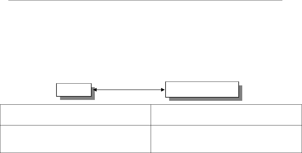
2.1.2 Reader to Host Interface Wire Types and Lengths
Refer to Table 2 to determine the recommended wiring type at various maximum reader to host
distances. Variation in distance requires different wire gauges. Because of system data termination
differences, contact your system manufacturer for exact requirements. Installation should be in
accordance with National Electric Code ANSI/NFPA 70.
Cable Type
Maximum Cable Length
22 AWG (0.80mm), six or eight conductor, with an
overall foil shield, Alpha 5196, 5198 or equivalent.
500’(152 m)
Note: To insure an active low level that is less than 0.6 V, the total ground resistance
from the reader to the controller must be less than 0.5 ohms. Use larger guage wire if
necessary.
Table 2. Reader to Host Interface Wire Types and Lengths
Reader Host Controller Panel
Cable Length

K02021-000 Rev A April 2006
8
2.2 Electrical Installation
2.2.1 Grounding
Connect the reader directly to an earth ground as shown in fugure 4. An earth ground can be established
by driving a copper clad ground rod into the earth. Make certain the DC resistance between your
established earth ground and the system ground is very low. If direct connection to a ground rod is not
possible, connect the reader to an earth-ground (do not connect to fire sprinkler system), or to steel frames
(building beams) that connect to earth.
Prevent ground loops by connecting the controller ground and the negative line of the power supply to
one common earth ground point. Connecting different points to separate earth grounds may result in a
ground loop. Ground loops may cause poor read range and communication line interference resulting in
no code or improper data transmission to the controller.
In a multiple reader installation, connect all readers to a single earth ground reference point (common
ground).
Figure 4. Grounding the Reader
Note: A multiple reader installation requires a higher maximum current rated power supply. See specifications” on page 2.
K02021-000 Rev A April 2006
9
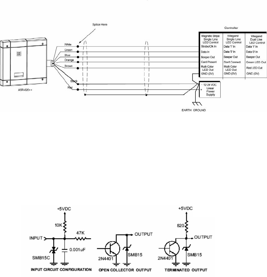
2.2.2 Reader to Host Interface Wiring
Figure 5 shows interfaces for Magstripe and Wiegand Host controllers.
Choose the appropriate interface for your installation.
(RS-232 configuration requires a BIL-422/232 Signal Conditioning Module which is sold separately.)
Figure 5. Magstripe and Wiegand Reader to Host Interface Wiring
Please observe the following:
• The system must have a single earth ground point.
• For open collector (non-terminated output), consult your system manufacturer for correct cable
length and type.
The internal circuit configurations for the reader inputs and outputs are as shown in Figure 6
Figure 6. Internal Circuit Configurations
K02021-000 Rev A April 2006
10
2.3 Tuning the Reader
Tuning the reader is not necessary in most installations. The reader should be mounted and tested for read
range and host output function prior to attempting an adjustment of the reader. Before attempting to tune
the reader, call Indala Technical Support at (800) 646-3252 or (408)361-4700 for instructions. The
installer should be familiar with the adjustment procedure and be able to correctly complete the
adjustment in a controlled environment prior to attempting to make adjustments at the installation
location.
Tuning the reader should not be attempted without the required tools and equipment. Improper or
incomplete tuning of the reader will significantly degrade reader performance and may invalidate
the Warranty.
K02021-000 Rev A April 2006
11
3.0 Operation
When power is first applied to the reader, it performs internal power up diagnostics. If it is functioning
properly, the reader will flash the LED and beep twice. After the power up diagnostics are completed and
the reader is in a READY status mode you may present a standard or option card to the reader.
3.1 Startup Diagnostic
The readers have an internal diagnostic routine to assure reader operation at start-up, as well as a means to
test the integrity of the data lines. When power is first applied to a reader, it will beep and flash twice to
let the installer know that it has performed an internal check and is functioning properly. If the reader
start-up routine determines one of the critical memory devices inside the reader has failed, the reader will
alternately flash the LED red and green.
K02021-000 Rev A April 2006
12
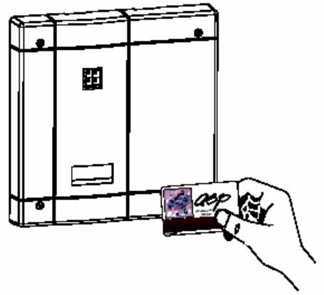
3.2 Presenting the Card
Figure 7. Presenting the Card
To obtain maximum read range, present the card to the reader as shown in Keeping the card parallel to
the ASR-620++ reader and move it slowly toward the face of the reader until a QuickFlash is obtained.
This is the point at which the card is read and the data is transmitted to the controller. To read the card
again, remove it from the reader field and present it again. During normal use, the card can be presented
to the reader at any angle, although this will result in a reduced read range.
QuickFlash
When a valid card is presented the LED will flash and the audio tone (beeper) will be
activated for 70 to 100 milliseconds, regardless of the card’s access status. This gives the
user immediate feedback that the card was read and that data was sent to the controller.
After the quickFlash period, the controller takes over control of the LED and beeper.
3.3 Data Output
The ASR-620++ reader is capable of outputting Wiegand, Magstripe, or RS-232 format (RS-232 requires
additional hardware). For further information please call technical support at (800) 646-3252 or (408)361-
4700
3.4 Verifying Data at Host
To verify that the data lines are good, put the reader into line test mode by holding a SelfTest card (Indala
part number 07257-001) in front of the reader. The reader will respond with an alternately flashing LED
in all three colors and an audio signal to let you know it is in the line test mode. The reader will remain in
the line test mode until power is removed and reapplied or the SelfTest, or any other applicable, card is
presented again. While in this mode, the reader will send output pulses down the data lines at a 1 Hz rate,
which can be measured at the controller end with a volt meter. If the pulses are not present, then there is
probably a break or short in the line. If the pulses are present and the system is still not working, the
reader may not be connected to the controller properly or the controller/ system may be incorrectly
programmed or the controller may be broken.

K02021-000 Rev A April 2006
13
3.5 Controls and Indications
3.5.1 Wiegand and Mag Stripe Single-Line Control LED Host to
Reader Interface Wiring
• There is no LED OFF state in this configuration.LED is red when the brown wire is high
(above 2.2 VDC or not connected).
• Pull brown wire low to change LED color to green.
• Toggle brown line high-low at a rate of 100 Hz to 1 kHz, 50% duty cycle, to produce amber
LED color.
• Pull blue beeper wire low to activate audio beep tone.
3.5.2 Wiegand Dual-Line Control LED Host to Reader Interface
Wiring
• The LED is OFF when both brown and orange wires are high (above 2.2 VDC or not con-
nected).
• Pull brown wire low to activate red LED.
• Pull orange wire low to activate green LED.
• Pull orange and brown wires low simultaneously to activate amber LED.
• Pull blue wire low to activate audio “beeper” tone.
3.5.3 Option Cards
3.5.3.1 Single-Line and Dual-Line LED Control
This option card toggles the state of the LED control lines (Indala part number 07260-001). If one beep is
heard when the card is presented, the reader is set to a single line LED control. If two beeps are heard, the
reader is set to a dual line LED control.
3.5.3.2 QuickFlash Beep Enable/Disable
This option card toggles the state of the QuickFlash beep option (Indala part number 07259- 001). If one
beep is heard when the card is presented to the reader, the automatic beep is enabled. If two beeps are
heard, the automatic QuickFlash beep is disabled.
3.5.3.3 QuickFlash LED Enable/Disable
This option card toggles the state of the QuickFlash LED option (Indala part number 07258- 001). If one
beep is heard when the card is presented to the reader, the automatic QuickFlash is enabled. If two beeps
are heard, the automatic QuickFlash LED is disabled.
K02021-000 Rev A April 2006
14
3.5.3.4 SelfTest Card
This option card enables or disables the line test mode upon presentation (Indala part number 07257-001).
Present the card once to put the reader into the line test mode. Present a second time to revert to normal
operation.
3.5.3.5 WatchDog Enable/Disable Card
This option card toggles the state of the automatic WatchDog option (Indala part number 07508-001). If
one beep is heard when the card is presented to the reader, the WatchDog output is enabled. If two beeps
are heard, the WatchDog output is disabled. The WatchDog will output an 8-bit “10101010” pattern
(hexadecimal “AA”) approximately once every minute over the data lines.
4.0 Troubleshooting
If the reader does not function properly when installed according to instructions, please call (800) 646-
3252 for technical assistance. International customers call (408) 361-4700:
K02021-000 Rev A April 2006
15
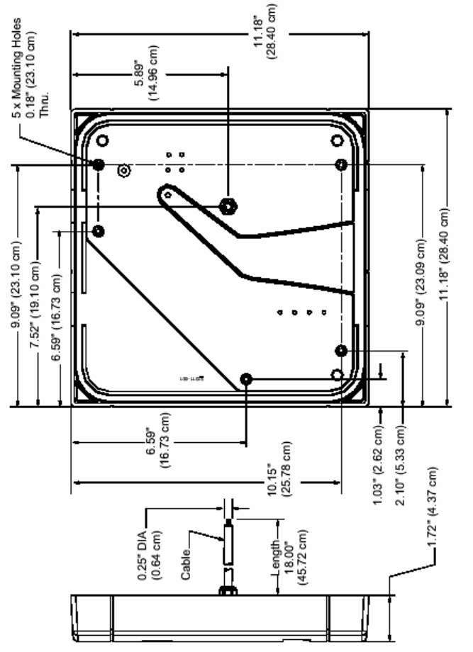
5.0 Additional Information
5.1 Mechanical Drawings
Figure 8. ASR-620++ Mechanical Dimensions

K02021-000 Rev A April 2006
16
5.2 Copyrights, Patents, and Trademark Credits
Indala Corporation reserves all rights including patents, copyrights, trademarks, trade names, and all other
intellectual property rights worldwide. No reproduction, adaptation, or translation is allowed without prior
written permission from Indala Corporation. Indala Corporation reserves the right to change any product
description and/or specification contained here without prior notice.
Products are covered by United States patent 4818855, Canadian patent 1253591, and other patents
pending worldwide.
5.3 RMA (Return Material Authorization)
Goods returned for repair, warranty or non-warranty, must be assigned an RMA (Return Material
Authorization) number. The customer is to provide a description of the specific problem. The customer is
to include serial numbers, formats, card ID numbers, and correct facility codes with the items to be
returned. If exact duplicates of returned cards or tags are requested, the customer must provide Motorola
Indala with the exact format and ID numbers needed.
For readers returned and not covered by the warranty (due to age, misuse and/or damage), a quote for
repairs will be issued, and no work will be performed until a valid purchase order is received. Readers
left over 30 days without a repair authorization and a purchase order will be returned with evaluation
charges and shipping costs applied.
5.4 Contacting Technical Support
U.S.A. Office: EMEA Office:
6850 B Santa Teresa Blvd. 8-10 Clos Menter
San Jose, CA 95119-1205 Excelsior Business Park
Tel (408) 361-4700, Main Cardiff CF14 3AY
Tel (800) 646-3252, Technical Support +44 29 2052 0022
Fax (408) 361-4701 Fax +44 29 2052 0178