HID Global DSMODEM-RTC Wireless-LAN modems User Manual Exhibit 13 Confidentiality
HID Global Corporation Wireless-LAN modems Exhibit 13 Confidentiality
manual

Integrated Information Systems Group
8201 E. McDowell Road
Scottsdale, AZ 85252-1417
Exhibit 8
Page 1 of 13FCC ID: E9UDSMODEM-RTC
12/21/00
Exhibit 8 – Users Manual
DSMODEM/RTC
Wireless LAN
FCC ID: E9UDSMODEM-RTC
Model No. DSMODEM/RTC
8.0 DSMODEM/RTC Users Manual
Exhibit 08

902 ~ 928 MHz Wireless-LAN
WS200 / WM200 User Manual 2001-01-09
LQWHUQDOXVHRQO\
Mt l S t dSlti K
902 ~ 928 MHz Wireless-LAN
WS200 / WM200 User Manual
Exhibit 08
902 ~ 928 MHz Wireless-LAN
WS200 / WM200 User Manual 2001-01-09
LQWHUQDOXVHRQO\
Mt l S t dSlti K
Table of Content
1. INTRODUCTION and FEATURES. ……………………………………………… 3
2. OUTSIDE. ……………..……………………………………………………………. 4
3. Setting and Using. ………………………………………………………………... 7
3.1. Prepare the WS200 / WM200 wireless-LAN.. ……………………………. 8
3.2. Connecting WS200 / WM200 wireless-LAN. ……………………………. 8
4. Application…………………………………………………………………………. 9
5. Technical Specifications………………………………………………………… 10
6. Trouble Shooting…………………………………………………………………. 11
This device complies with Part 15 of the FCC rules.
Operation is subject to the following two conditions: (1) This device
may not cause harmful interference. And (2) this device must accept
any interference received, including interference that may cause
undesired operation.
1. Introduction and Features
1.1. WS200 / WM200 ( MSSK’ s RF-LAN ) receives and transmits data in the Industrial,
Scientific and Medical (ISM) band of 902 to 928 MHz by half-duplex mode. WS200
Exhibit 08
902 ~ 928 MHz Wireless-LAN
WS200 / WM200 User Manual 2001-01-09
LQWHUQDOXVHRQO\
Mt l S t dSlti K
/ WM200 wireless-LAN uses a standard RS-232C serial data external-interface
that can be driven asynchronously. WS200 / WM200 wireless-LAN uses direct
sequence spread spectrum technology implemented with Spread Spectrum
Technology (SST). This can be applied for multiple-access networking or point-to-
point, point-to-multiple, and multiple-to-multiple communication.
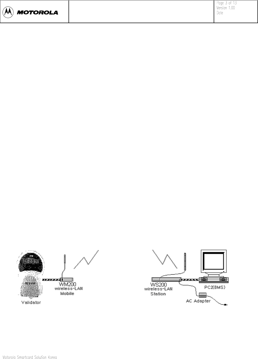
1.2. WS200 / WM200 is consisting with Station(WS200) and Mobile(WM200) Parts.
Mobile(WM200) is connected by Validator, and Station(WS200) is connected by
BMS (Data Gathering System). Mobile and Station can RF-communication with
each other.
1.3. Major features of the WS200 / WM200 wireless-LAN include:
•Designed for 902-928 MHz ISM band
•Auto channel scan and channel indication
•Auto channel change when interfered
•Spurious emission meets FCC part 15 class B and 15.247
•High immunity to interference and jamming
•Long range
•High security
•Compact size
•Easy to operate
•Low cost
<Figure 1-1, OneValidator connection with one BMS, via Mobile and Station.>
2. Outside & Configuration
Exhibit 08
902 ~ 928 MHz Wireless-LAN
WS200 / WM200 User Manual 2001-01-09
LQWHUQDOXVHRQO\
Mt l S t dSlti K
2.1. Mobile has one connector, LED indicators.
1. RS-232 & Power
Connector A DB-9 connector for connecting to data terminal equipment
(DTE) and +12~+24V DC power input.
1,6 Power +12~+24V DC power input.
2 TX of RF-LAN RS-232C communication TX-line of RF-LAN.
3 RX of RF-LAN RS-232C communication RX-line of RF-LAN.
4,5,9 GND GND
2. Power LED This LED turns on when DC-Power on.
3. Status 1 LED This LED display Wireless-LAN’s Status.
4. Status 2 LED This LED display Wireless-LAN’s Status.
5. Wired TX LED This LED turns on when Wired TX-signal is.
6. Wired RX LED This LED turns on when Wired RX-signal is.
7. Wireless TX LED This LED turns on when Wireless TX-signal is.
8. Wireless RX LED This LED turns on when Wireless RX-signal is.
9. DIP Switch (Not Defined.)
Inside located. (Can’t view on outside.)
Exhibit 08
902 ~ 928 MHz Wireless-LAN
WS200 / WM200 User Manual 2001-01-09
LQWHUQDOXVHRQO\
Mt l S t dSlti K
2.2. Mobile Configuration
A. Mobile
<Figure 2-1, Mobile LEDs >
<Figure 2-2, Mobile connectors >
B. Mobile’s Antenna & Antenna Cable
C. Mobile’s Communication/Power Cable
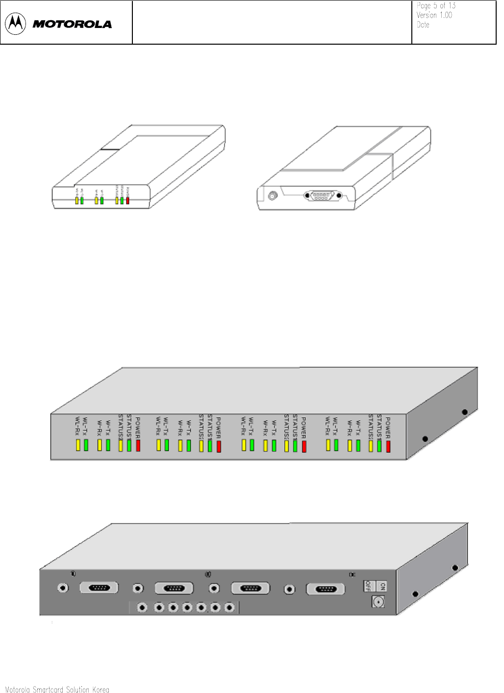
2.3. Station Configuration
A. Station
<Figure 2-3, Station LEDs >
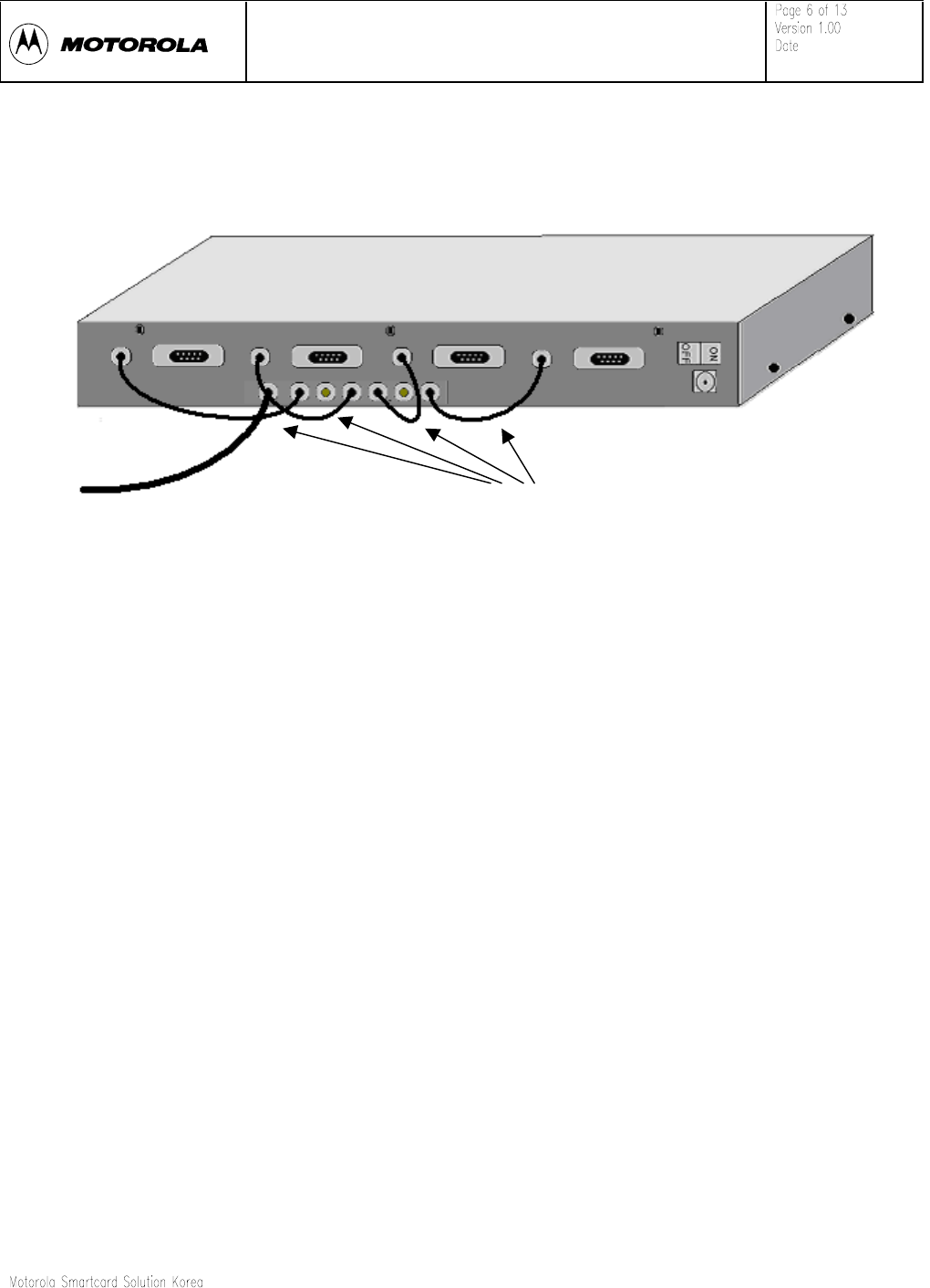
<Figure 2-4, Station connectors >
Exhibit 08
902 ~ 928 MHz Wireless-LAN
WS200 / WM200 User Manual 2001-01-09
LQWHUQDOXVHRQO\
Mt l S t dSlti K
B. Station’s Antenna & Antenna Cable
C. Station’s Antenna Extension Cables
<Figure 2-5, Station’s Antenna connection >
D. Station’s Communication Cables
E. Station’s Power Adapter & Power Cable
Antenna Extension Cables
Antenna Cable
Exhibit 08
902 ~ 928 MHz Wireless-LAN
WS200 / WM200 User Manual 2001-01-09
LQWHUQDOXVHRQO\
Mt l S t dSlti K
3. Setting and Using
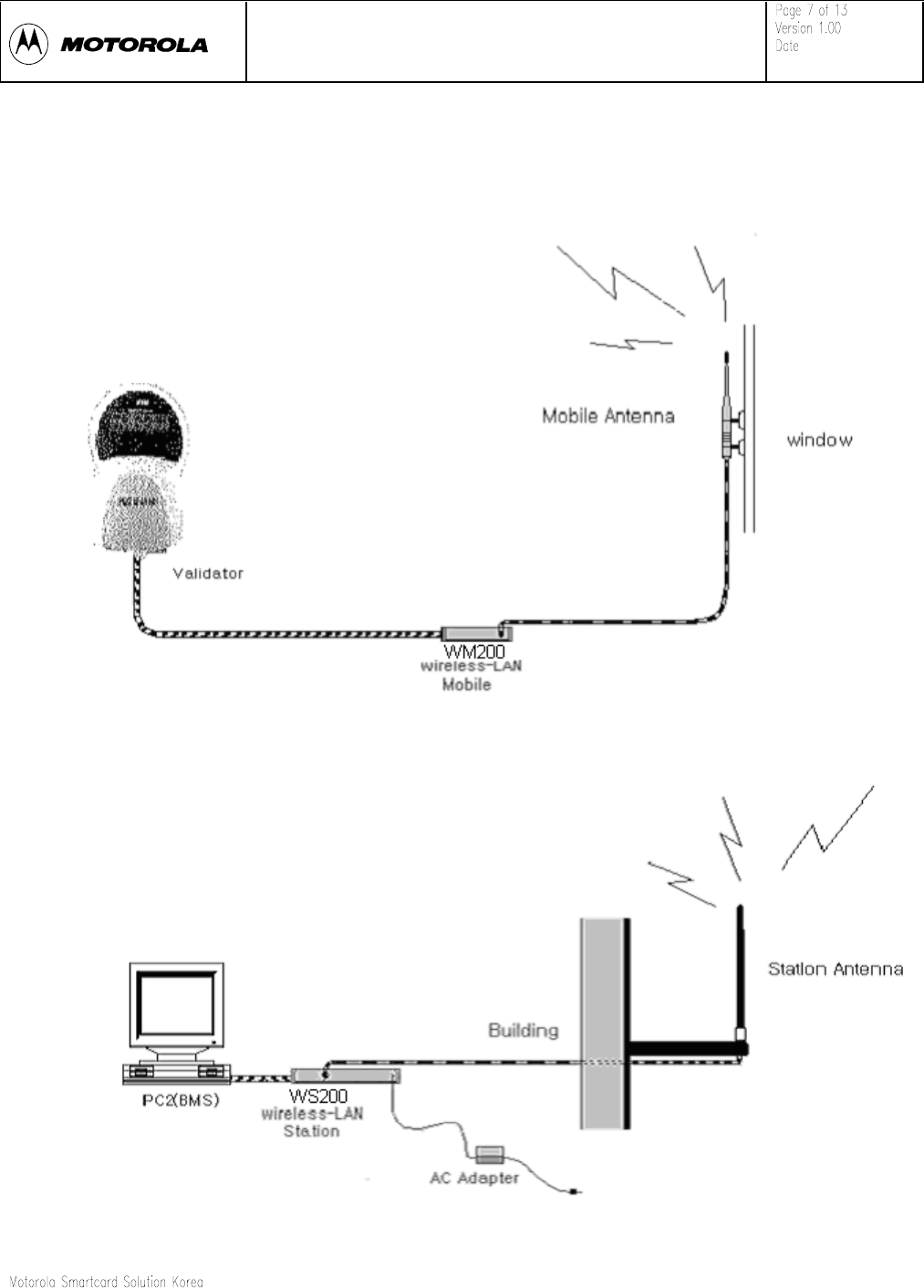
<Figure 3-1, Mobile connection with Validator, Antenna >
Exhibit 08

902 ~ 928 MHz Wireless-LAN
WS200 / WM200 User Manual 2001-01-09
LQWHUQDOXVHRQO\
Mt l S t dSlti K
<Figure 3-2, Mobile connection with Validator, Antenna and AC adapter>
3.1. Prepare the WS200 / WM200 wireless-LAN
The following sections describe how to connect the WS200 / WM200 wireless-
LAN to External Device and how to set up and operate the WS200 / WM200
wireless-LAN.
3.1.1. Those following equipment will be used to set up the system, but the system
operation should be verified by qualified personnel in MSSK and professionally
installed.
3.1.2. One Validator and One PC for BMS.
3.1.3. One WM200 Mobile.
3.1.4. One RS-232 cable (with power-line) for Mobile.
3.1.5. One Mobile (WM200)’s Antenna & Antenna Cable (200mm Dipole Antenna :
specified by MSSK).
3.1.6. One WS200 Station.
3.1.7. Four RS-232 cables (with no power-line) for Station. (Station use AC-Power
adapter.)
3.1.8. Four Station (WS200)’s Antenna Extension Cables
3.1.9. One Station (WS200)’s Antenna & Antenna Cable (800mm Whip Antenna :
specified by MSSK).
3.1.10. AC Power Adapter & Power Cable for Station.
3.2. Connecting WS200 / WM200 wireless-LAN
To connect both the wireless modems, please do the following procedures.
For Mobile,
A. One side of RS-232 cable connects the serial port of Validator , and the
other side connects with the rear of Mobile.
B. Mobile’s antenna & antenna cable connects with Mobile. (Please, do not use
other device might cause the rf-power variation.)
C. Place the antenna on window of BUS.
D. Validator power on, then the power indicator-LED on Mobile will turn on.
(+24V power deriving by Validator)
Exhibit 08
902 ~ 928 MHz Wireless-LAN
WS200 / WM200 User Manual 2001-01-09
LQWHUQDOXVHRQO\
Mt l S t dSlti K
For Station,
A. One side of the RS-232 cable connects connector on the rear panel of
Station, and the other side connects with the serial port of PC (BMS).
B. Four-antenna extension cables connect on each point. (See Figure 2-5)
C. Station’s antenna & antenna cable connects with Station. (Please, do not use
other device might cause the rf-power variation.)
D. Place the antenna on higher position.
E. Plug the AC power adapter (AC to 24VDC) into power inlet of the Station and
power on.
F. Then power indicator-LED on the Station will turn on.
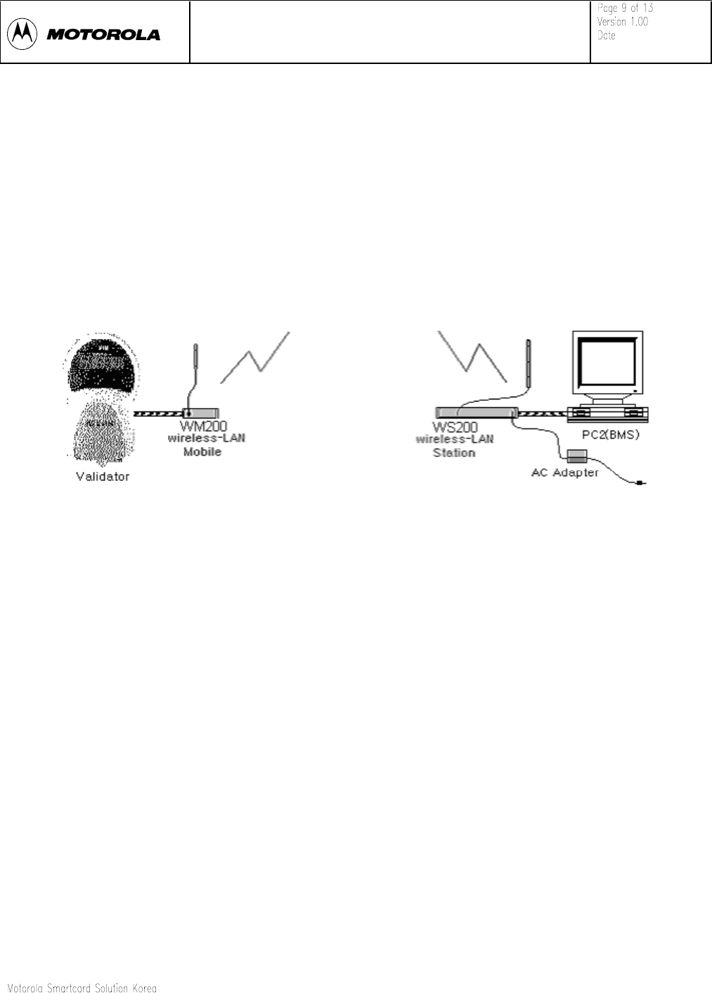
<Figure 3-3, One Validator connection with one BMS, via Mobile and Station.>
4. Applications
Wireless Networking
With appropriate operating(wireless application program), data of the WS200 / WM200
within a workgroup may be shared without physically connect them together.
Exhibit 08
902 ~ 928 MHz Wireless-LAN
WS200 / WM200 User Manual 2001-01-09
LQWHUQDOXVHRQO\
Mt l S t dSlti K
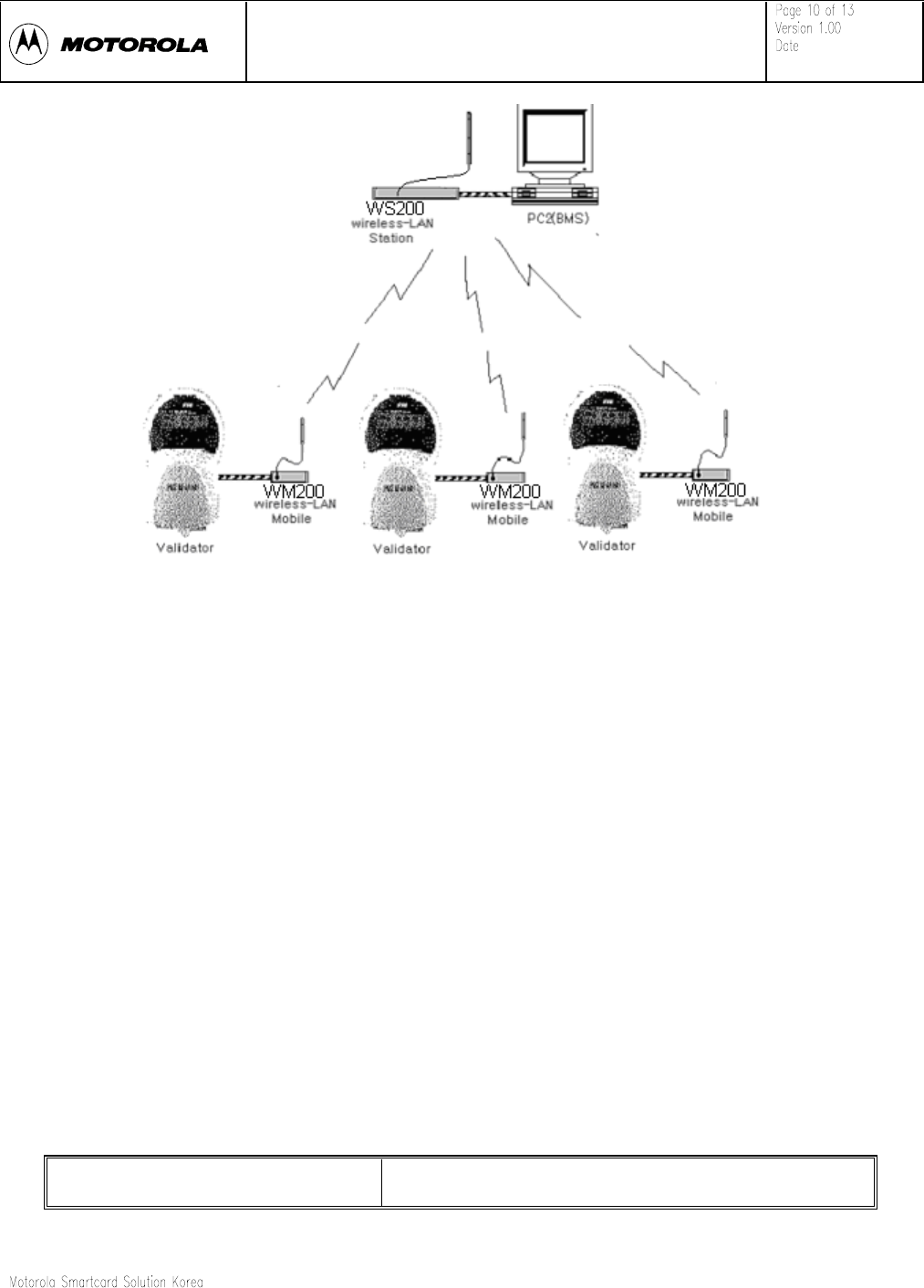
<Figure 4-1, Three Validators is connecting with one BMS, via Mobiles and
Station.>
5. Technical Specifications
RF-Frequency Range 902-928MHz
Exhibit 08
902 ~ 928 MHz Wireless-LAN
WS200 / WM200 User Manual 2001-01-09
LQWHUQDOXVHRQO\
Mt l S t dSlti K
RF-Channel Spacing 2.048 MHz
RF-Transmission Power 20 ± 2 dBm
RF-Modulation Scheme GMSK
RF-Radio Technique Direct Sequence Spread Spectrum
RF-Duplex Mode Half-duplex
RF-Number of Channel 10
RF-Operation Mode Point-to-point
RF-PN Code Chip Rate 1.365 M chips/sec
RF-Data Format Async, 170 Kbps, 8-bit, Even-parity, 1-Stop-bit
Wired External Interface RS-232-C, DB-9 Connector (with Power Pin)
Wired Data Format Async, 115 Kbps, 8-bit, No-parity, 1-Stop-bit
DATA FORMAT Transparent
Data Bit Error Rate 10-3 @ -100 dBm
Operating Temperature 0 °C to 60 °C
Storage Temperature -30 °C to 70 °C
Supply Voltage +12~24 VDC
Transmitter CurrentConsumption < 200mA @ 24VDC
Receiver Current Consumption < 150mA @ 24VDC
Power Consumption < 4.8W (Mobile)/ < 20W (Station)
Spurious Emission Compliance FCC part 15 class B and 15.247
Antenna 50 ohms (omni-directional)
6. Trouble Shooting
6.1. When Mobile/Station do not display power LED.
Exhibit 08
902 ~ 928 MHz Wireless-LAN
WS200 / WM200 User Manual 2001-01-09
LQWHUQDOXVHRQO\
Mt l S t dSlti K
A. Check wired connection condition.
B. Reconnect wired connection.
C. Please. Call repair-department.
6.2. When Status LED didn’t flicker by 10-second, periodically.
A. Check wired connection condition.
B. Reconnect wired connection. (And, Please. Call repair-department.)
6.3. When Validator display “RF1”-> “Fail” (Mobile can’t wired-communicate with
validator).
A. Check wired connection condition.
B. Reconnect wired connection. (And, Please! Call repair-department.)
6.4. When BMS display “Wired communication is failed”(Station can’t wired-
communicate with BMS).
A. Check wired connection condition.
B. Reconnect wired connection. (And, Please. Call repair-department.)
6.5. When Mobile can’t communicate with Station (Wireless-communication can’t
more). Validator’s display : “RF2 -> Fail”, BMS’s display : “Wireless communication
is failed”
A. Check Mobile condition.
B. Check distance of Mobile and Station.
C. Check Mobile antenna right up and antenna’s connectors.
(Antenna condition checking.)
D. Check Station antenna right up and antenna’s connectors.
(Antenna condition checking.)
E. Please. Call repair-department
Exhibit 08