HID Global EDOC RFID Reader User Manual
HID Global Corporation RFID Reader
user manual

Copyright © 2007 – Integrated Engineering 1
Desktop ISO 14443-4 reader
Desktop ISO 14443-4 reader with OCR
Desktop ISO 14443-4 reader with OCR QA
Installation guide
Integrated Engineering
By : Dennie de Waart
Date : 28th of November 2007
Document : ISO 14443-4 USB reader installation
ISO 14443-4 USB reader with OCR installation
ISO 14443-4 USB reader with OCR QA installation
Version : 6.0

Copyright © 2007 – Integrated Engineering 2
This manual is applicable for the following products:
• 800-8250 Desktop/ISO14443-4/e-Doc
• 800-8252 Desktop/ISO14443-4/e-Doc+AED
• 800-8251 Desktop/ISO14443-4/e-Doc+OCR
• 800-8253 Desktop/ISO14443-4/e-Doc+OCR+AED
• 800-8255 Desktop/ISO14443-4/e-Doc+OCR/QA
• 800-8254 e-Passport add-on

Copyright © 2007 – Integrated Engineering 3
Table of contents
1. Introduction 4
1.1 Document purpose 4
1.2 Document version history 4
1.3 Document validity 4
1.4 Remarks 4
1.5 Installation possibilities 4
2. Specifications 5
2.1 Power supply 5
2.2 Fuse 5
2.3 USB cable 5
2.4 Certifications 5
3. ISO 14443-4 USB reader - driver installation 6
3.1 General procedure overview 6
3.2 Prerequisites 6
3.3 Step 1: Connect the reader to the PC 6
3.4 Step 2: Installing the USB driver 6
4. ISO 14443-4 USB reader with OCR - driver installation 11
4.1 General procedure overview 11
4.2 Prerequisites 11
4.3 Step 1: Access Keyboards driver installation 11
4.4 Step 2: Connect the reader to the power 15
4.5 Step 3: Connect the reader to the PC 16
4.6 Installing the USB driver 16
4.7 Verification Access Keyboard driver 20
5. ISO 14443-4 USB reader with OCR QA 21
5.1 General procedure overview 21
5.2 Prerequisites 21
5.3 Step 1: Connect the reader to the power 21
5.4 Step 2: Connect the reader to the PC 21
5.5 Step 3: Connect the Serial QA reader to the PC 21
5.6 Step 4: Installing the USB driver 21
5.7 Step 5: Using the QA (Quality Assurance) reader 26
5.8 Working with QADemo 27
6. BSI – GoldenReader tool installation 28
6.1 Prerequisites 28
6.2 Running the GoldenReader tool directly from CD 28
6.3 Installing GoldenReader tool on your hard disk 28
6.4 Configuring the GoldenReader Tool 29
7. Appendix A - GoldenReader tool screens 30
8. Appendix B - GoldenReader tool read-me file 32
9. Appendix C – Notes on reading performance 33

Copyright © 2007 – Integrated Engineering 4
1.1 Document purpose
This document describes the software installation procedure for Integrated
Engineering's ISO 14443-4 USB readers. This installation procedure consists of four
parts:
1. Installation of the ISO 14443-4 USB reader drivers.
2. Installation of the ISO 14443-4 USB reader with OCR drivers
3. Installation of the ISO 14443-4 USB reader with OCR QA drivers
4. Installation of BSI (Bundesamt für Sicherheit in der Informationstechnik) LDS
GoldenReader tool.
1.2 Document version history
Version 4.0 1st of July 2006 revised document.
Installation guide for Integrated Engineering ISO 14443-4 USB reader, ISO 14443-4
USB with OCR, ISO 14443-4 USB with OCR QA and BSI Golden Reader tool (GRT for
short) under Microsoft Windows 2000 and Windows XP Professional.
1.3 Document validity
This document applies only for Microsoft Windows 2000 and Windows XP
Professional.
This manual is written based on Windows 2000. The order of installation steps and
screenshots may slightly vary for Windows XP.
1.4 Remarks
1. The ISO 14443-4 reader is powered from the PC's USB port. To function the
reader requires a USB port that supplies 5 Volt. The reader will not function on
USB ports that supply 3.3 Volt.
2. The ISO 14443-4 USB reader with OCR and ISO 14443-4 USB reader with OCR
QA is powered by an AC/DC adapter 12V DC 2,4A. These readers are protected
with a fuse (F1.6AL250V).
3. The ISO 14443-4 e-Doc with OCR Quality Assurance uses RTS/CTS handshaking.
4. In some occasions when the reader is disconnected and reconnected Windows
fails to detect the reader. If this occurs. Please log off and log on in order for
Windows to reinitialise its drivers.
5. BSI's Golden Reader tool is a demonstration tool. The tool is not intended for
benchmarking.
1.5 Installation possibilities
● For the driver installation of an ISO 14443-4 USB reader, article number 800-
8250 proceed with chapter 3.
● For the driver installation of an ISO 14443-4 USB reader with OCR, article
number 800-8251 proceed with chapter 4.
● For the driver installation of an ISO 14443-4 USB reader with OCR QA, article
number 800-8255 proceed with chapter 5.
1. Introduction

Copyright © 2007 – Integrated Engineering 5
2.1 Power supply
Max 5 V DC.
2.2 Fuse
The e-Document readers with OCR use a F1.6AL250V fuse.
2.3 USB cable
The maximum length of the USB cable is 2.9 meter
2.4 Certifications
FCC / CANADA RADIO CERTIFICATION
These devices comply with part 15 of the FCC rules.
Operation is subject to the following two conditions: (1) This device may not cause harmful interference, and (2)
This device must accept any interference received, including interference that may cause undesired operation.
Changes or modifications not expressly approved by the party responsible for compliance could void the user's
authority to operate the equipment.
Le fonctionnement est soumis aux deux conditions suivantes : (1) Ce dispositif ne peut pas causer de perturbations
nuisibles et (2) ce dispositif doit accepter toute perturbation quelconque qu’il reçoit, y compris des perturbations
susceptibles de provoquer un fonctionnement indésirable. Les changements ou modifications n’ayant pas été
expressément approuvés par la partie responsable de la conformité peuvent faire perdre à l’utilisateur l’autorisation
de faire fonctionner le matériel.
CE MARKING
HID Global hereby declares that these proximity readers are in compliance with the essential requirements and
other relevant provisions of Directive 1999/5/EC.
Por el presente, HID Global declara que estos lectores de proximidad cumplen con los requisitos esenciales y otras
disposiciones relevantes de la Directiva 1999/5/EC.
HID Global déclare par la présente que ces lecteurs à proximité sont conformes aux exigences essentielles et aux
autres stipulations pertinentes de la Directive 1999/5/EC.
A HID Global, por meio deste, declara que estes leitores de proximidade estão em conformidade com as exigências
essenciais e outras condições da diretiva 1999/5/EC.
HID Global bestätigt hiermit, dass die Leser die wesentlichen Anforderungen und anderen relevanten
Bestimmungen der Richtlinie 1999/5/EG erfüllen.
HID Global dichiara che i lettori di prossimità sono conformi ai requisiti essenziali e ad altre misure rilevanti come
previsto dalla Direttiva europea 1999/5/EC.
2. Specifications
Copyright © 2007 – Integrated Engineering 6
3.1 General procedure overview
This procedure describes the installation steps for the ISO 14443-4 USB reader USB
driver. These installation steps are valid only for Windows 2000 and Windows XP
Professional.
3.2 Prerequisites
1. Before proceeding, make sure that the PC is switched on and running.
2. Make sure the CD is placed in the CDROM player.
3. This installation instruction requires that Windows plug-and-play for USB devices
is enabled.
4. USB driver installation is only required when an Integrated Engineering USB
reader is connected to a PC for the very first time.
3.3 Step 1: Connect the reader to the PC
● Connect the reader to a USB port of the PC.
● The reader will respond with seven times red LED, seven times green LED and
after that a beep when the PC is running and the USB port is functioning
properly.
● In case of CCID configuration LED F2 will flash green.
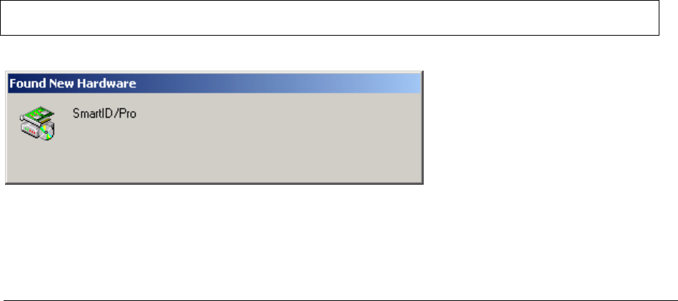
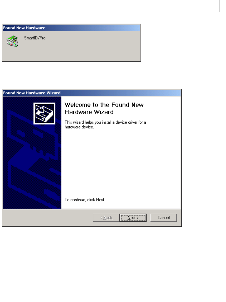
3.4 Step 2: Installing the USB driver
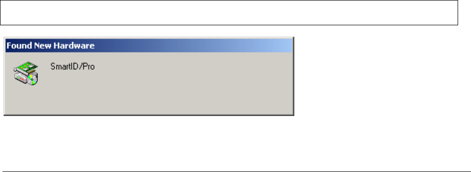
When the reader is plugged in the USB port and Windows plug-and-play for USB
devices is functioning properly, Windows will display the "Found new Hardware"
dialog displayed in Figure 1. The Integrated Engineering ISO 14443-4 reader is
recognised by Windows as SmartID/Pro or SmartID/CCID.
Note:
The following examples show the installation of the SmartID/Pro reader.
The installation of the SmartID/CCID reader is identical.
Figure 1: Windows Found new Hardware dialog
3. ISO 14443-4 USB reader - driver installation

Copyright © 2007 – Integrated Engineering 7
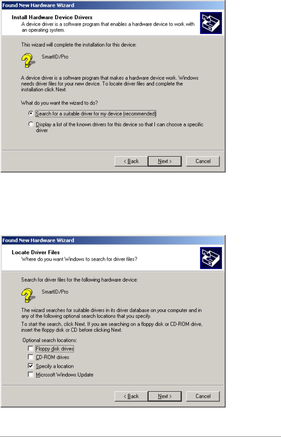
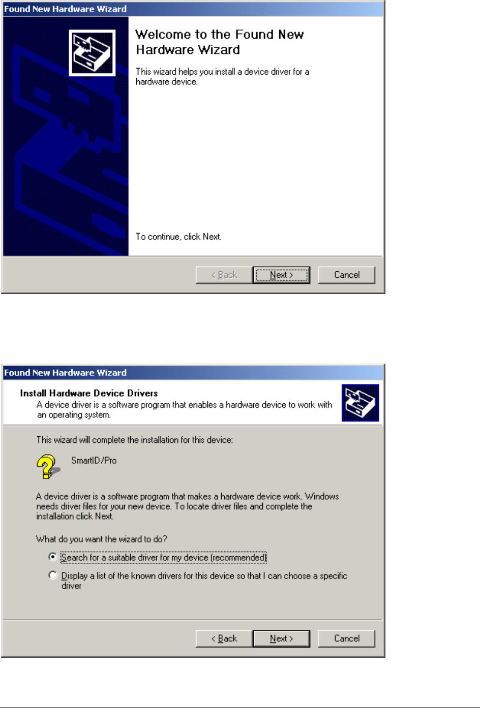
After searching its internal driver database Windows will display the Found New Hardware
Wizard to allow the installation of the USB driver for the reader see Figure 2.
Figure 2: Windows Found new hardware wizard dialog
Click on the "Next" button to proceed with the installation of the USB driver. The "Found
new hardware wizard" displays a new screen see Figure 3.
Figure 3: Select hardware drivers location

Copyright © 2007 – Integrated Engineering 8
Select "Search for a suitable driver for my device (recommended)" to allow Windows to
locate the correct drivers automatically. Click on the "Next" button to proceed. The Found
new hardware wizard will display a new screen to specify the locations to search for the
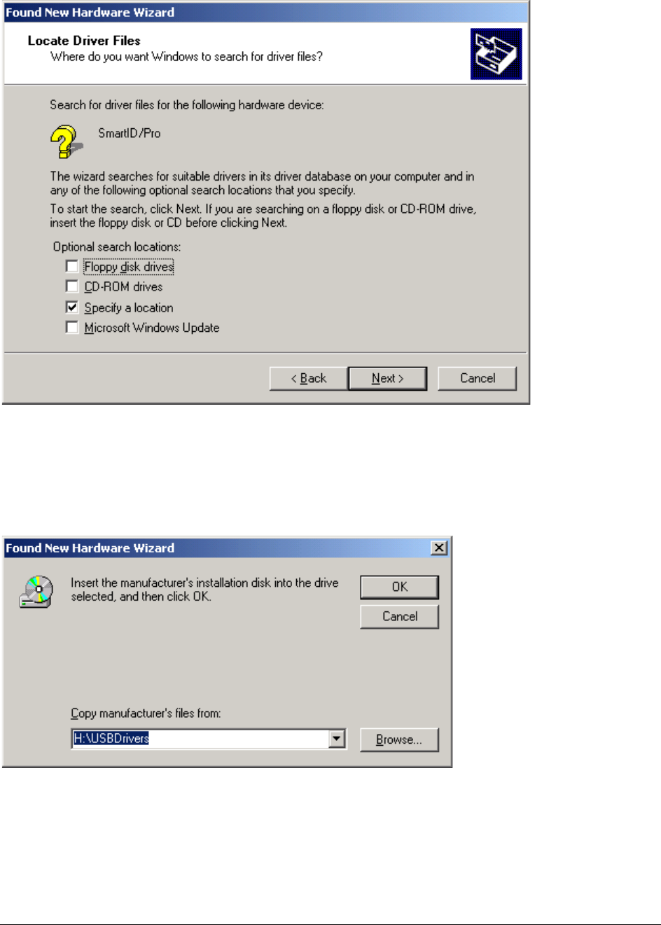
required drivers see Figure 4.
Figure 4: Select location to search for drivers
Place a "Check mark" in the Specify a location field and remove all other "Check marks" by
clicking in the field next to options. The value of the options will toggle if you click a field
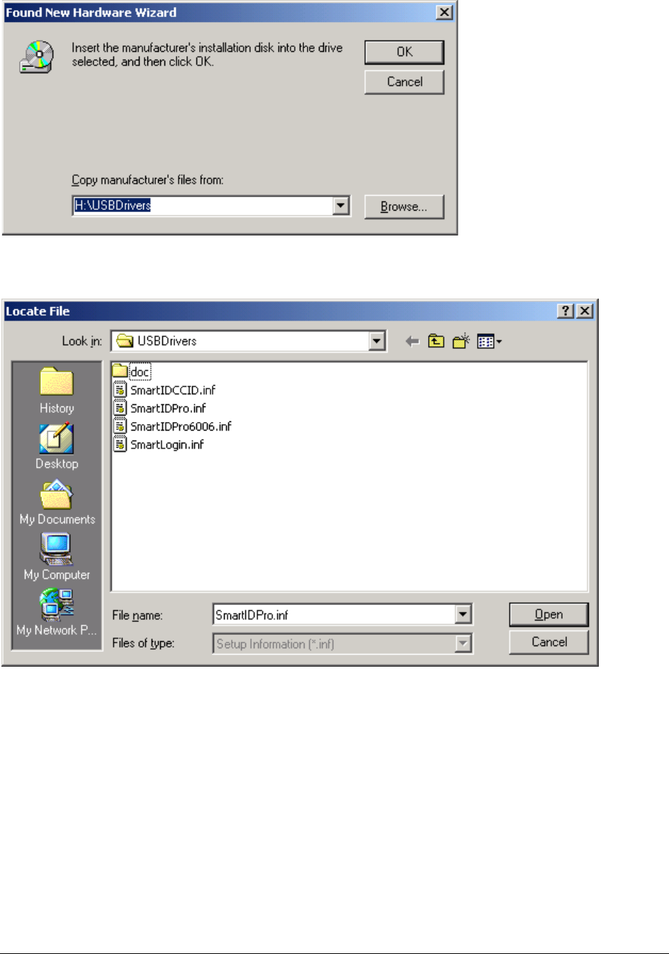
more than once. Press "Next" to proceed. The installation driver dialog Figure 5 opens.
Figure 5: Driver location dialog

Copyright © 2007 – Integrated Engineering 9
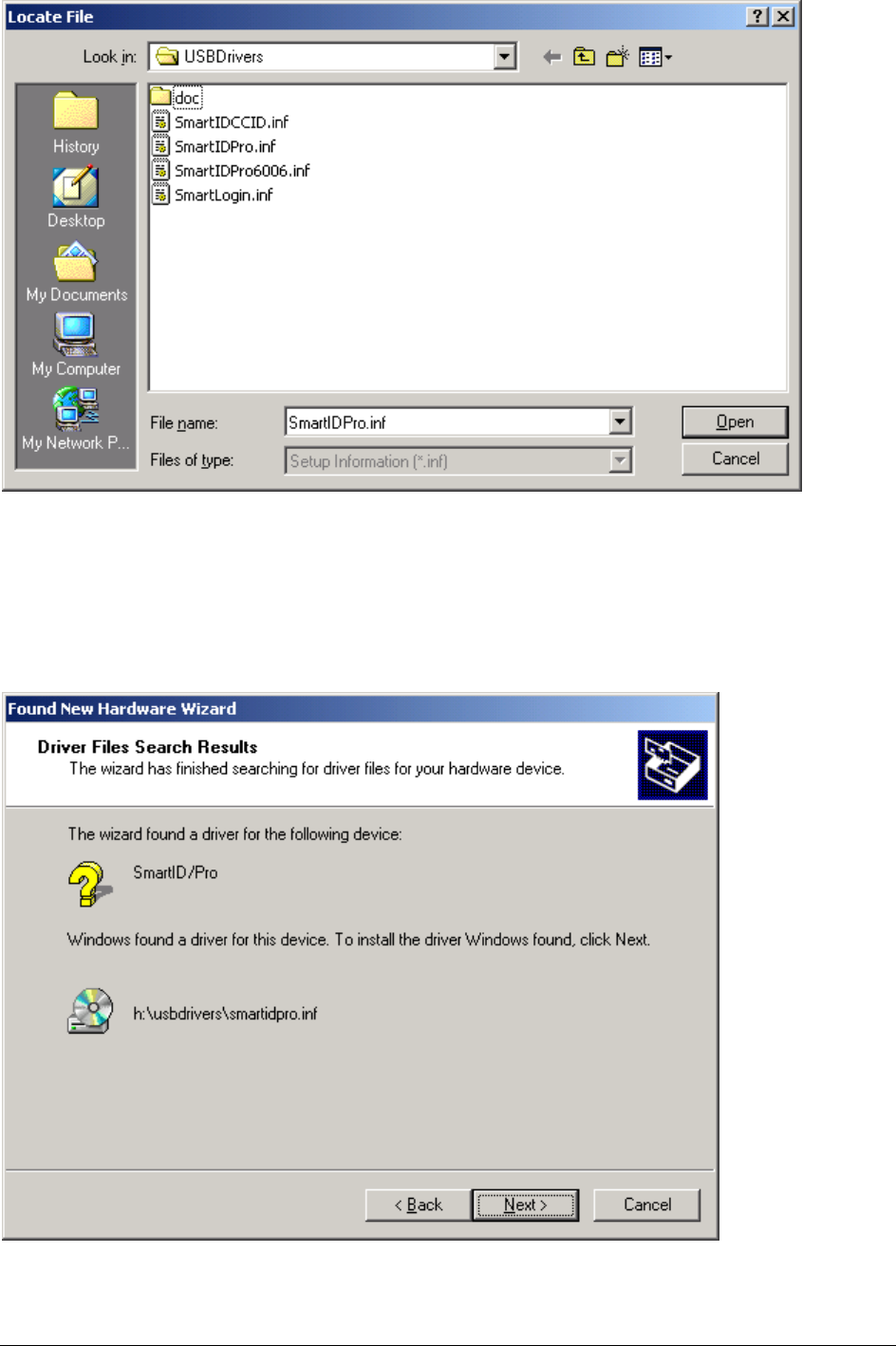
Click on the "Browse…" button to open the browse dialog see Figure 6.
Figure 6: Locate driver file(s) dialog
Make sure the CDROM with the "GoldenReader" tool that holds the USB drivers is placed in
the CDROM drive. Navigate with the Locate File dialog to the "USBDriver" directory on the
CD. Select the file SmartIDPro.inf and click on the Open button. The Found New Hardware
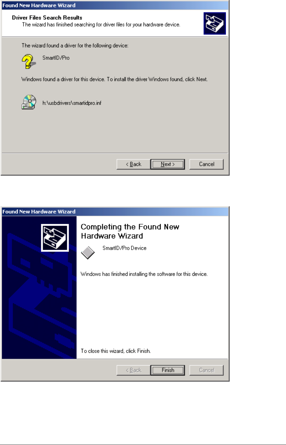
Wizard will display a screen to display the search results Figure 7.
Figure 7: Driver Files Search Results
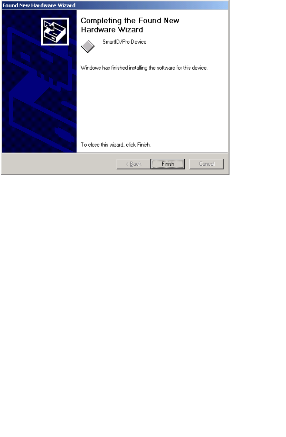
Click on the Next button to confirm the installation of the displayed driver. The Found New
Hardware Wizard displays the final screen to confirm that the driver is installed Figure 8.
Copyright © 2007 – Integrated Engineering 10
Figure 8: Confirmation of installed driver
The installation of the USB driver for the reader is completed, click on Finish to close the
Found New Hardware Wizard.
In some occasion Windows will display a message requesting a reboot of the PC to finalise
the installation of the driver. Please reboot the PC by following the instructions on the
screen.
Copyright © 2007 – Integrated Engineering 11
4.1 General procedure overview
This procedure describes the installation steps for the ISO 14443-4 USB reader with
OCR drivers. These installation steps are valid only for Windows 2000 and Windows
XP Professional.
4.2 Prerequisites
1. Before proceeding, make sure that the PC is switched on and running.
2. Make sure the CD is placed in the CDROM player.
3. This installation instruction requires that Windows plug-and-play for USB devices
is enabled.
4. USB driver installation is only required when an Integrated Engineering USB
reader is connected to a PC for the very first time.
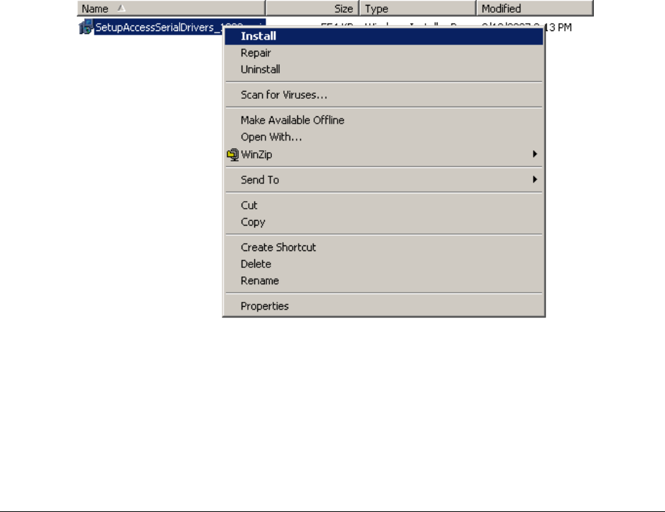
4.3 Step 1: Access Keyboards driver installation
1. Open the "Access Keyboards" folder on the installation CD.
2. Open the "Driver" folder in the "Access Keyboards" folder.
3. Right mouse click on the SetupAccessSerialDrivers_1020.msi file.
● See AK Picture 1.
AK Picture 1
4. Select "Install".
● The following window will appear.
● See AK Picture 2.
4. ISO 14443-4 USB reader with OCR - driver installation
Copyright © 2007 – Integrated Engineering 12
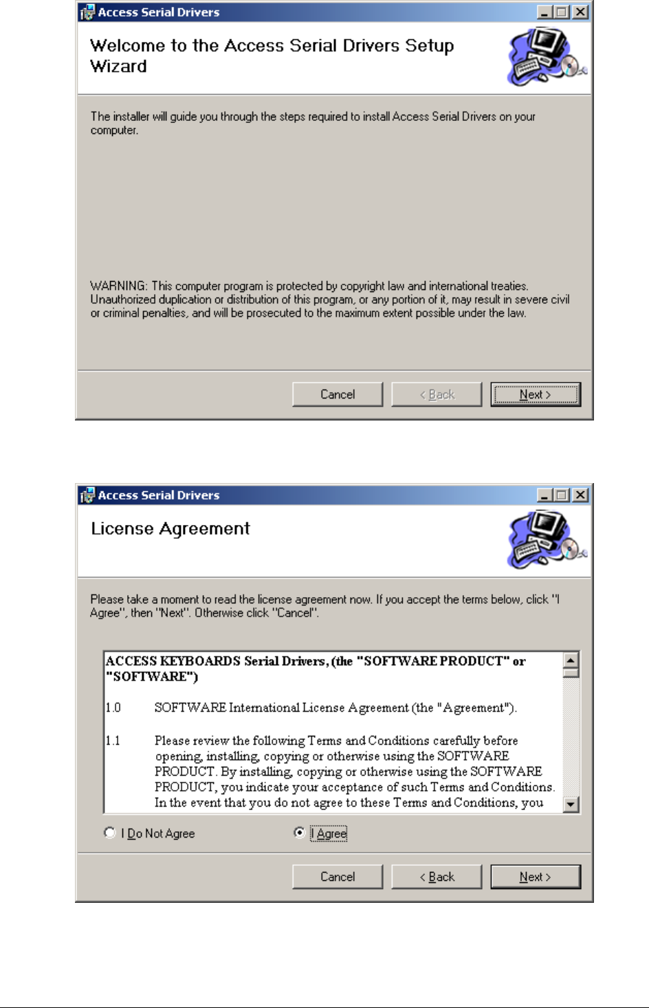
AK Picture 2
5. Click on "Next".
● The following window will appear.
AK Picture 3
6. Select "I Agree" and click on "Next".
● The following window will appear.
Copyright © 2007 – Integrated Engineering 13
AK Picture 4
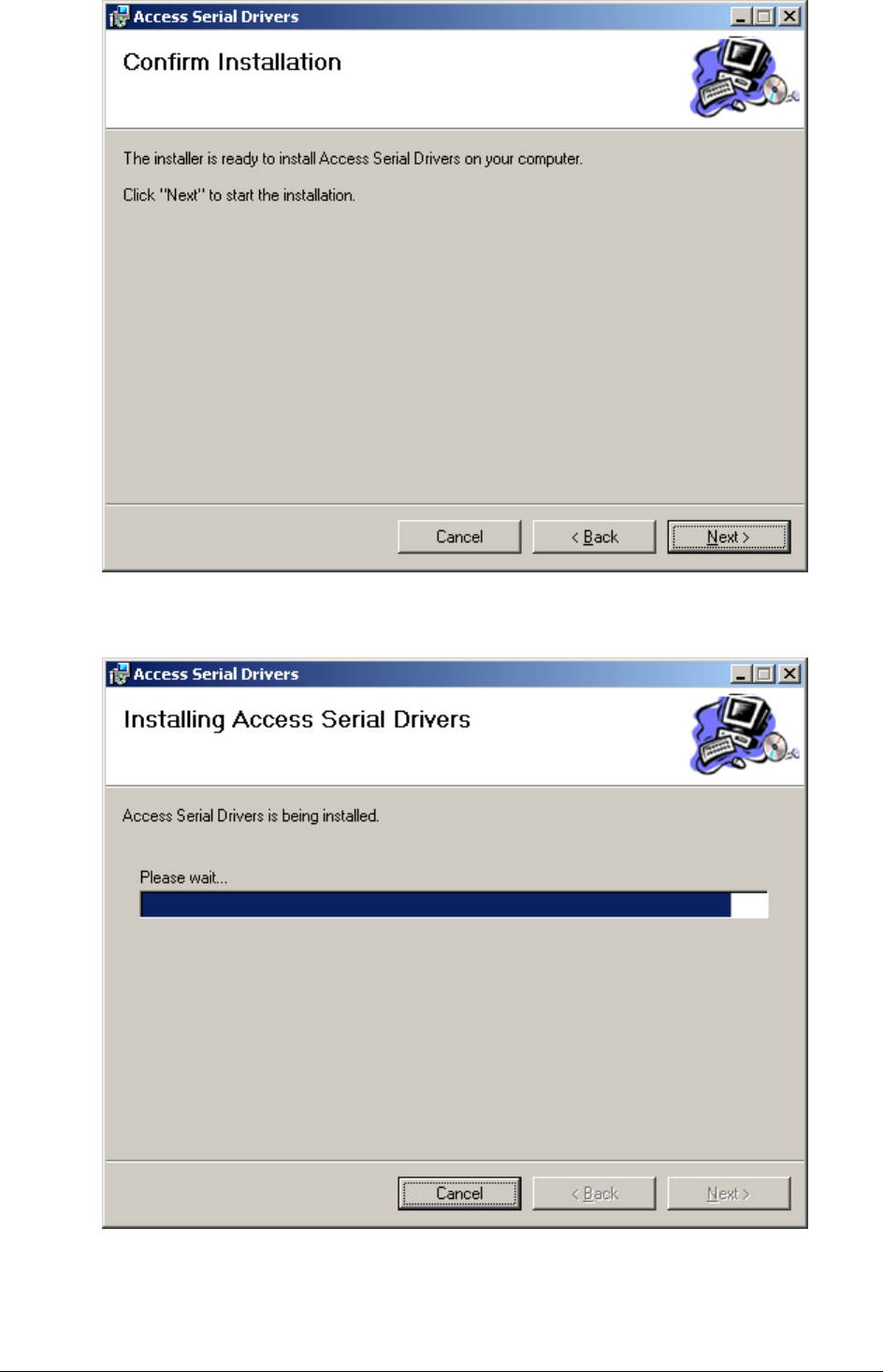
7. Select "I Agree" and click on "Next".
● The following window will appear and shows the progress indicator.
AK Picture 5
8. Click on "Next" when the progress indicator is finished.
● The following window will appear.
Copyright © 2007 – Integrated Engineering 14
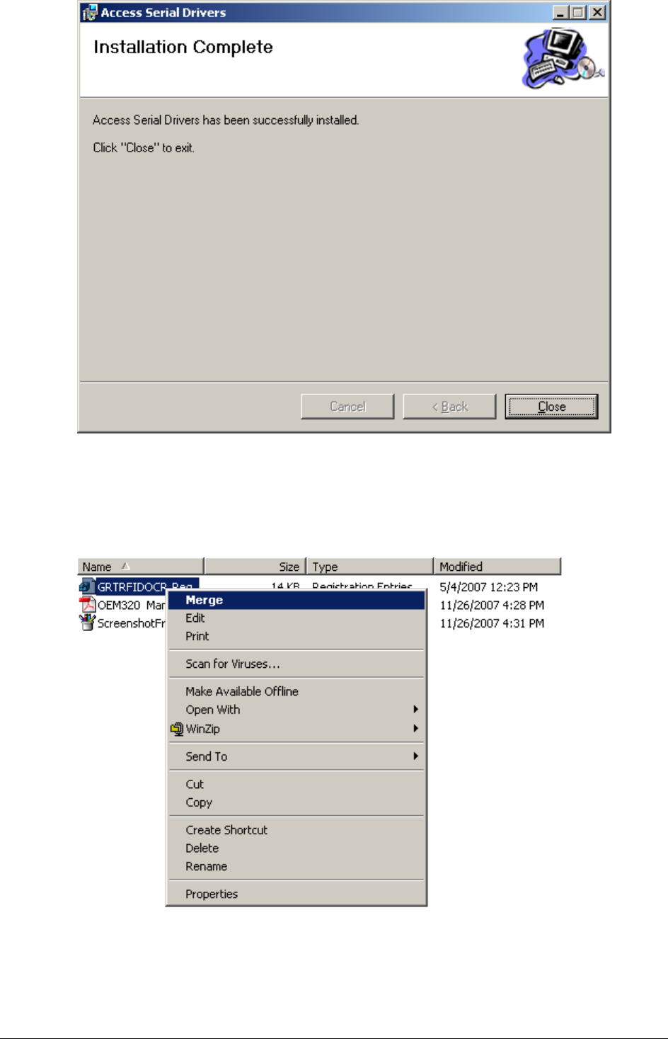
AK Picture 6
9. The driver installation is finished. Click on "Close" to exit.
10. Open the "IERSettings" folder in the "Access Keyboards" folder.
11. Right mouse click on the GRTRFIDOCR.Reg file.
● See AK Picture 7.
AK Picture 7
Copyright © 2007 – Integrated Engineering 15
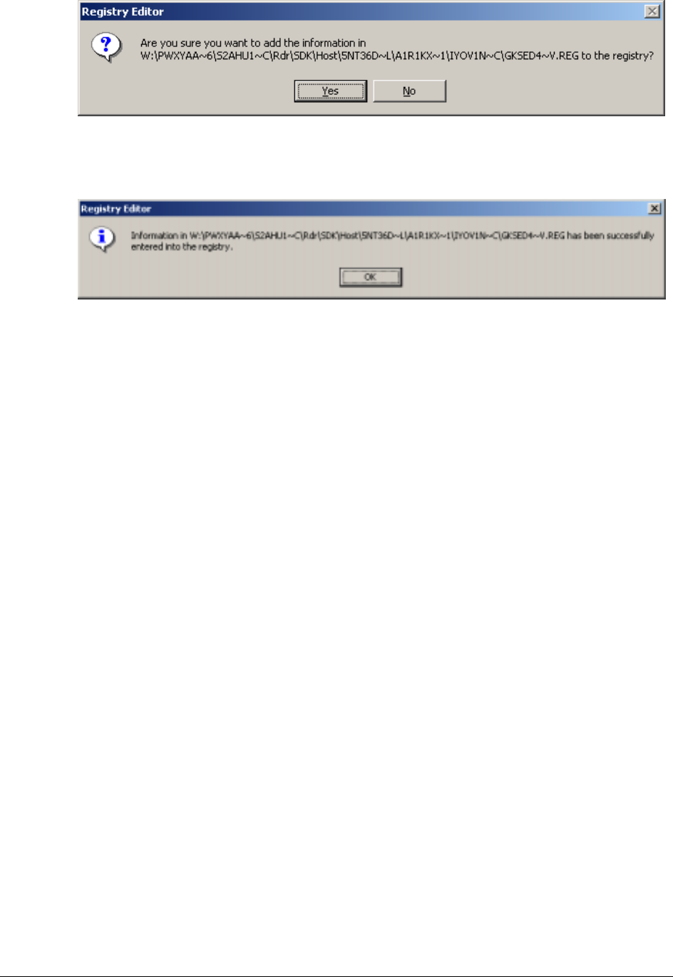
12. Select "Merge".
● The following window will appear.
● See AK Picture 8.
AK Picture 9
13. Click on "Yes".
● The following window will appear.
AK Picture 10
14. Click on "OK".
● The installation is finished.
4.4 Step 2: Connect the reader to the power
● The reader will respond with seven times red LED, seven times green LED and
after that a beep when it is functioning properly.
● In case of CCID configuration LED F2 will flash green.
4.5 Step 3: Connect the reader to the PC
● Connect the reader to a USB port of the PC.
Copyright © 2007 – Integrated Engineering 16
4.6 Step 4: Installing the USB driver
When the reader is plugged in the USB port and Windows plug-and-play for USB
devices is functioning properly, Windows will display the "Found new Hardware"
dialog displayed in Figure 1. The Integrated Engineering ISO 14443-4 reader is
recognised by Windows as SmartID/Pro or SmartID/CCID.
Note:
The following examples show the installation of the SmartID/Pro reader.
The installation of the SmartID/CCID reader is identical.
Figure 9: Windows Found new Hardware dialog
After searching its internal driver database Windows will display the Found New Hardware
Wizard to allow the installation of the USB driver for the reader see Figure 2.
Figure 10: Windows Found new hardware wizard dialog
Click on the "Next" button to proceed with the installation of the USB driver. The "Found
new hardware wizard" displays a new screen see Figure 3.
Copyright © 2007 – Integrated Engineering 17
Figure 11: Select hardware drivers location
Select "Search for a suitable driver for my device (recommended)" to allow Windows to
locate the correct drivers automatically. Click on the "Next" button to proceed. The Found
new hardware wizard will display a new screen to specify the locations to search for the
required drivers see Figure 4.
Figure 12: Select location to search for drivers
Copyright © 2007 – Integrated Engineering 18
Place a "Check mark" in the Specify a location field and remove all other "Check marks" by
clicking in the field next to options. The value of the options will toggle if you click a field
more than once. Press "Next" to proceed. The installation driver dialog Figure 5 opens.
Figure 13: Driver location dialog
Click on the "Browse…" button to open the browse dialog see Figure 6.
Figure 14: Locate driver file(s) dialog
Make sure the CDROM with the "GoldenReader" tool that holds the USB drivers is placed in
the CDROM drive. Navigate with the Locate File dialog to the "USBDriver" directory on the
CD. Select the file SmartIDPro.inf and click on the Open button. The Found New Hardware
Wizard will display a screen to display the search results Figure 7.
Copyright © 2007 – Integrated Engineering 19
Figure 15: Driver Files Search Results
Click on the Next button to confirm the installation of the displayed driver. The Found New
Hardware Wizard displays the final screen to confirm that the driver is installed Figure 8.
Figure 16: Confirmation of installed driver
The installation of the USB driver for the reader is completed, click on Finish to close the
Found New Hardware Wizard.
In some occasion Windows will display a message requesting a reboot of the PC to finalise
the installation of the driver. Please reboot the PC by following the instructions on the
screen.

Copyright © 2007 – Integrated Engineering 20
4.7 Verification Access Keyboard driver
After the installation of the SmartReader USB driver, the Access Keyboard driver needs to
be verified. Windows will display the "Found new Hardware" dialog and automatically
installs the driver for the Serial Bridge and USB Human Interface Device.
New Hardware Found 1 2 3
Copyright © 2007 – Integrated Engineering 21
- driver installation
5.1 General procedure overview
This procedure describes the installation steps for the ISO 14443-4 USB reader with
OCR drivers. These installation steps are valid only for Windows 2000 and Windows
XP Professional.
5.2 Prerequisites
1. Before proceeding make sure that the PC is switched on and running.
2. Make sure the CD is placed in the CDROM player.
3. This installation instruction requires that Windows plug-and-play for USB devices
is enabled.
4. USB driver installation is only required when an Integrated Engineering USB
reader is connected to a PC for the very first time.
5.3 Step 1: Connect the reader to the power
● The reader will respond with three times red LED, three times green LED and
after that a beep when it is functioning properly.
● In case of CCID configuration LED F2 will flash green.
5.4 Step 2: Connect the reader to the PC
● Connect the USB reader to a USB port of the PC.
5.5 Step 3: Connect the Serial QA reader to the PC
● Connect the QA reader to a serial port of the PC.
5.6 Step 4: Installing the USB driver
When the reader is plugged in the USB port and Windows plug-and-play for USB
devices is functioning properly, Windows will display the "Found new Hardware"
dialog displayed in Figure 1. The Integrated Engineering ISO 14443-4 reader is
recognised by Windows as SmartID/Pro or SmartID/CCID.
Note:
The following examples show the installation of the SmartID/Pro reader.
The installation of the SmartID/CCID reader is identical.
Figure 17: Windows Found new Hardware dialog
5. ISO 14443-4 USB reader with OCR QA
Copyright © 2007 – Integrated Engineering 22
After searching its internal driver database Windows will display the Found New Hardware
Wizard to allow the installation of the USB driver for the reader see Figure 2.
Figure 18: Windows Found new hardware wizard dialog
Click on the "Next" button to proceed with the installation of the USB driver. The "Found
new hardware wizard" displays a new screen see Figure 3.
Figure 19: Select hardware drivers location
Copyright © 2007 – Integrated Engineering 23
Select "Search for a suitable driver for my device (recommended)" to allow Windows to
locate the correct drivers automatically. Click on the "Next" button to proceed. The Found
new hardware wizard will display a new screen to specify the locations to search for the
required drivers see Figure 4.
Figure 20: Select location to search for drivers
Place a "Check mark" in the Specify a location field and remove all other "Check marks" by
clicking in the field next to options. The value of the options will toggle if you click a field
more than once. Press "Next" to proceed. The installation driver dialog Figure 5 opens.
Figure 21: Driver location dialog
Copyright © 2007 – Integrated Engineering 24
Click on the "Browse…" button to open the browse dialog see Figure 6.
Figure 22: Locate driver file(s) dialog
Make sure the CDROM with the "GoldenReader" tool that holds the USB drivers is placed in
the CDROM drive. Navigate with the Locate File dialog to the "USBDriver" directory on the
CD. Select the file SmartIDPro.inf and click on the Open button. The Found New Hardware
Wizard will display a screen to display the search results Figure 7.
Figure 23: Driver Files Search Results
Click on the Next button to confirm the installation of the displayed driver. The Found New
Hardware Wizard displays the final screen to confirm that the driver is installed Figure 8.

Copyright © 2007 – Integrated Engineering 25
Figure 24: Confirmation of installed driver
The installation of the USB driver for the reader is completed, click on Finish to close the
Found New Hardware Wizard.
In some occasion Windows will display a message requesting a reboot of the PC to finalise
the installation of the driver. Please reboot the PC by following the instructions on the
screen.
Trouble shooter:
In case of disconnecting the power plug accidentally, or disconnecting the reader from
the PC Soft6700KBWedgeD.exe needs to be restarted.
When the power or USB connection is cut always first shut Soft6700KBWedgeD.exe
before reconnecting the reader.
Always first put the power on the reader and after that connect the reader to the PC.
By disconnecting the OCR reader from the PC first disconnect the serial connection then
the USB connection and after that disconnect the power.
Copyright © 2007 – Integrated Engineering 26
5.7 Step 5: Using the QA (Quality Assurance) reader
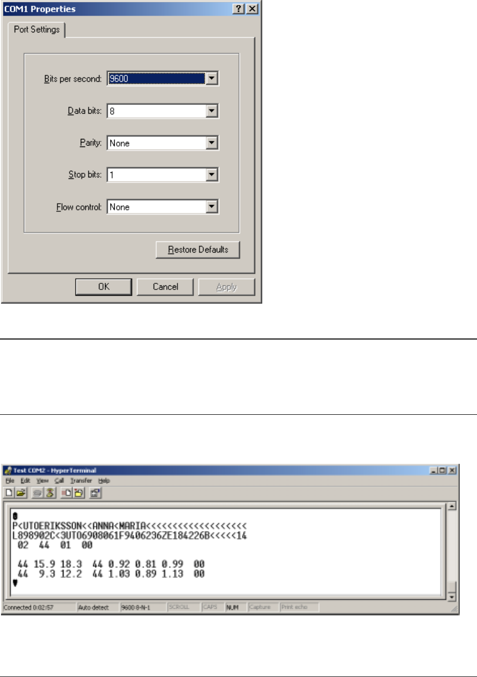
When using Hyper Terminal, the following settings need to be set.
COM properties Hyper Terminal
Note:
The RTE6510 QA requires RTS/CTS handshaking (i.e. the host PC should assert RTS to
enable the reader to send data or you must use a loop back dongle).
HyperTerminal and this QADemo version set RTS high so that the loop back dongle (for
handshaking) is not required.
For meaningful results, make sure that the page or card with the MRZ slides over the
bottom of the track of the optical scanner.
Hyper Terminal screenshot of a swiped two line MRZ
Copyright © 2007 – Integrated Engineering 27
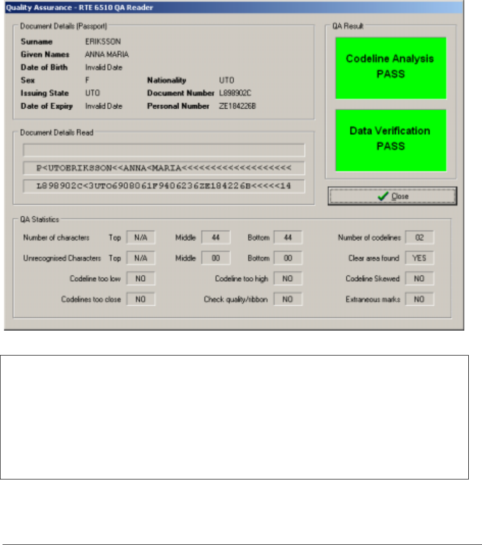
5.8 Working with QADemo
With the QA demo you can test the two or three line MRZ.
● Power up the reader.
● Connect the reader to the PC:
! Serial and USB connection
● Open application QADemo.exe.
! The Rochfort Thompson Equipment Limited main window will appear.
● Choose "QA" and after that "Check Document".
! The Quality Assurance main window will appear.
● Swipe the passport or ID-card with the MRZ through the optical scanner.
! The test results will appear in the Quality Assurance main window.
! See figure below.
Note:
The reader is already calibrated and configured to a speed index 100mm/s to 1000mm/s.
There’s no need to change these settings.
However, if it is required to use calibration and configuration cards, use Hyper Terminal
and ensure the correct size of the cards, which should be 125mm wide and 88mm high.
With the QA Calibration Height Setup form it’s possible calibrate the scanner.
With the RTE6510 QA Customer Information form it’s possible to set the speed
of the MRZ swipe.

Copyright © 2007 – Integrated Engineering 28
6.1 Prerequisites
Before attempting to install BSI's GoldenReader tool make sure of the following:
1. The PC is switched on and running.
2. The CD is placed in the CDROM player.
3. The USB driver of Integrated Engineering's ISO 14443-4 reader is loaded.
6.2 Running the GoldenReader tool directly from CD
BSI's GoldenReader tool can run directly from the CD without installation on the PC
hard disk. However due to practical reasons, like not being able to store configuration
settings, this is not advised.
6.3 Installing GoldenReader tool on your hard disk
1. Start Microsoft Windows Explorer.
2. Double click on the "My Computer" Icon in the "Folder" pane on the left.
● The "My Computer" folder will unfold.
3. Double click on the CDROM Icon
● The right pane of Windows Explorer will display the contents of the CD.
4. Right mouse click on the "GoldenReaderTool" folder and select copy from the
menu.
5. Double click on the "C: disk Icon" in the left pane of Microsoft explorer.
6. Right click on the "Program Files" folder and select paste.
● The contents of the CDROM folder "GoldenReaderTool" is now copied to
"C:\Program Files".
7. Click on the following folders: "Program Files", "GoldenReaderTool",
"GoldenReader_xxx" * to navigate to the directory where the GoldenReader tool
is installed.
● The right pane of Windows Explorer displays the installed GoldenReader files.
8. Right click on "GoldenReader.exe" and select Send To => Desktop (create
shortcut).
* "xxx" is the version number of GoldenReader Tool
6. BSI – GoldenReader tool installation

Copyright © 2007 – Integrated Engineering 29
6.4 Configuring the GoldenReader Tool
1. Start the GoldenReader tool by double clicking the "GoldenReader" Icon on your
desktop.
● The welcome screen of the GoldenReader tool will appear see Figure 23 in chapter
7. Appendix A - GoldenReader tool screens.
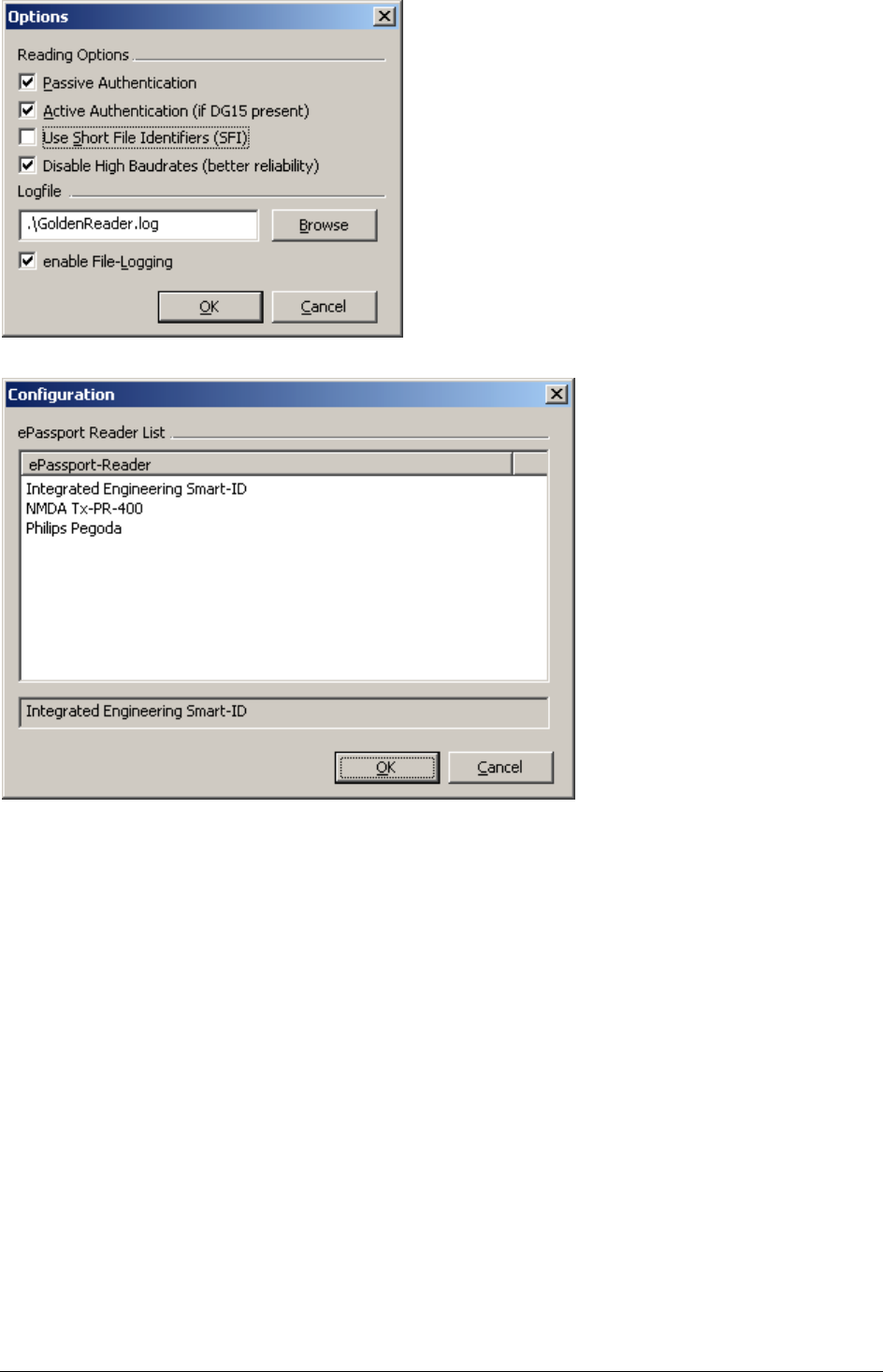
2. Click on the Configuration button.
● The Configuration dialog will appear. See Figure 26 in chapter 7. Appendix A -
GoldenReader tool screens.
3. Select the reader to use with GoldenReader Tool:
● IE SmartID/CCID 0
● Integrated Engineering Smart-ID
● NMDA Tx-PR-400
● Philips Pegoda
4. Click on the "OK" button to confirm and save the reader settings.
● The GoldenReader tool is now ready for use.
Note:
For IE ISO14443-4 USB PCSC/CCID readers the configuration dialog will display:
⇒ IE SmartID/CCID 0
If more IE ISO14443-4 USB PCSC/CCID readers are connected they will be displayed as:
⇒ IE SmartID/CCID 0
⇒ IE SmartID/CCID 1
⇒ IE SmartID/CCID …
Copyright © 2007 – Integrated Engineering 30
Figure 23: GoldenReader tool welcome screen
Figure 24: GoldenReader tool main window
7. Appendix A - GoldenReader tool screens
Copyright © 2007 – Integrated Engineering 31
Figure 25: GoldenReader tool Options dialog
Figure 26: GoldenReader tool Configuration dialog

Copyright © 2007 – Integrated Engineering 32
READ-ME FILE
The Golden Reader Tool on this CD has been developed for the Bundesamt für
Sicherheit in der Informationstechnik (BSI) in Bonn, Germany. BSI has allowed
Integrated Engineering (IE) to supply this Golden Reader Tool (GRT) with the IE
reader which has been integrated in this GRT.
The Golden Reader Tool has been developed to support, facilitate and promote
interoperability between various chips and RFID readers. The GRT is subject to
changes and/or updates.
The GRT you have now received represents the status of the GRT of the moment
the release of this version by BSI. BSI wants to be able to communicate changes
and/or updates in the GRT to its recipients. Therefore the Bundesamt für Sicherheit
in der Informationstechnik will be informed by Integrated Engineering who receives
the Golden Reader Tool through Integrated Engineering, including an E-mail
address.
In case you need any support with the GRT please contact Integrated Engineering
at +31 20 4620755, or by E-mail at info@smart-id.com
8. Appendix B - GoldenReader tool read-me file

Copyright © 2007 – Integrated Engineering 33
Reading speed from chip to application dependents on a number factors such as
chip type, chip OS, application (like GoldenReader tool) and CPU speed.
To achieve maximum reading speed with the GoldenReader tool make sure to
switch all the following application options in the GoldenReader tool: Passive
authentication, Use SFI and extended file-logging.
BSI's GoldenReader tool is a demonstration tool. It is not intended for
benchmarking. The following is a partial quote from communication between
Secunet and Integrated Engineering:
QUOTE
The GRT is not optimized for speed. Due to the design of the rf_api
(which was developed during another project) there are several
redundant operations while receiving multiple files consecutiveley
(e.g. select DFs). But the GRT never should be a speed demonstration
tool. Stability was the first object while developing the rf-api.
Special Card Reader "speedups" are also not supported. PC/SC-Readers
are all handled equally. Just the special and serial readers are
initialized using highest possible speeds regarding to supplied vendor
examples.
What we discovered:
- Extended logging costs time due to the extensive logging of APDUs
- CPU speed affects transfer rates
- CPU type does not
UNQUOTE
Additionally the GoldenReader tool performance is dependent on the available
processing power. Other processor intensive applications running at the same
moment will influence the reading performance of the GoldenReader tool.
9. Appendix C – Notes on reading performance

Copyright © 2007 – Integrated Engineering 34
Notes

Copyright © 2007 – Integrated Engineering 35
Notes

Copyright © 2007 – Integrated Engineering 36
The crossed-out wheeled bin means that within the European Union the
product must be taken to separate collection at the product end-of life. This
applies to your device but also to any enhancements marked with this
symbol. Do not dispose of these products as unsorted.
© Copyright 2006
Issue: July 2006 – This manual supercedes and renders invalid all earlier versions. The
information in this manual can be changed without prior notice.
The information in this manual has been put together to the best of the authors’ knowledge
and conscience. The manufacturers accepts no liability for the accuracy or completeness of
the information in this manual. In particular, the manufacturer cannot be held liable for
consequential damages caused as a result of incorrect or incomplete information. As it is
impossible to avoid mistakes despite all our efforts, we are always grateful if these are
pointed out.
The installation recommendations contained in this manual assume the most favorable
framework conditions. The manufacturer cannot guarantee that the system will function
perfectly under other conditions.
The manufacturer cannot guarantee that the information contained in this document is not
protected by external property rights. The manufacturer is not granting licenses to its own
or external patents or other property right.