HID Global SE3210 iCLASS SE Reader Module User Manual WinEDS 3
HID Global Corporation iCLASS SE Reader Module WinEDS 3
UserManual.wiki
>
HID Global
>
SE3210 User Manual
User Manual
Navigation menu
Upload a User Manual
Namespaces
Wiki Guide
HTML
PDF
Info
Views
User Manual
Discussion / Help
Navigation
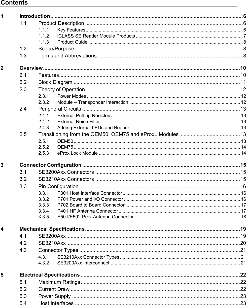
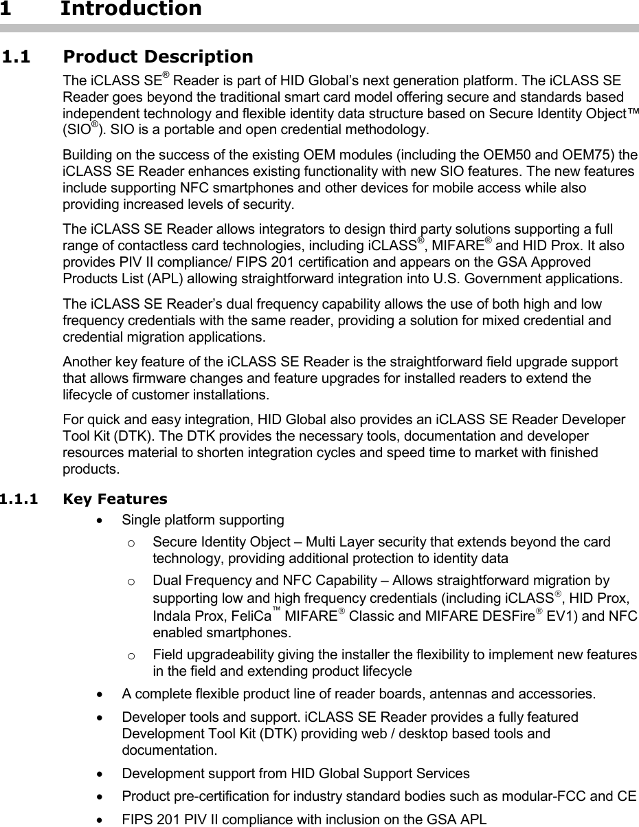
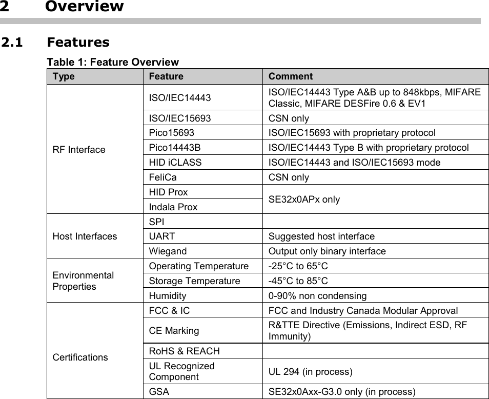
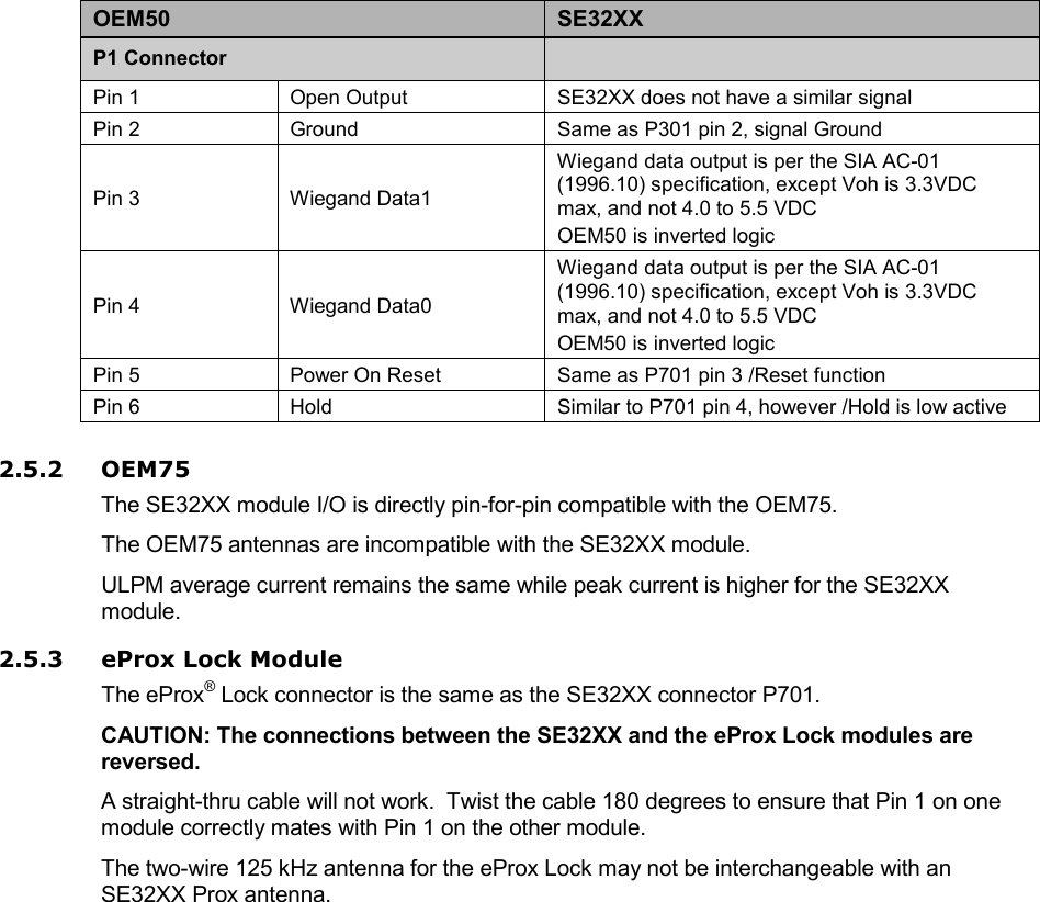
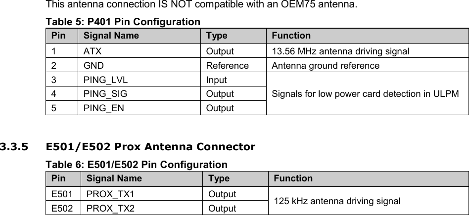
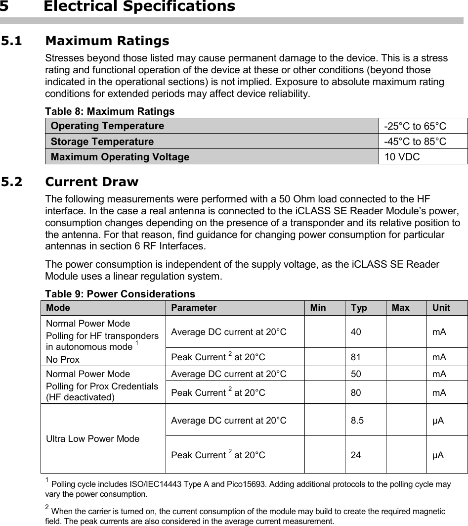
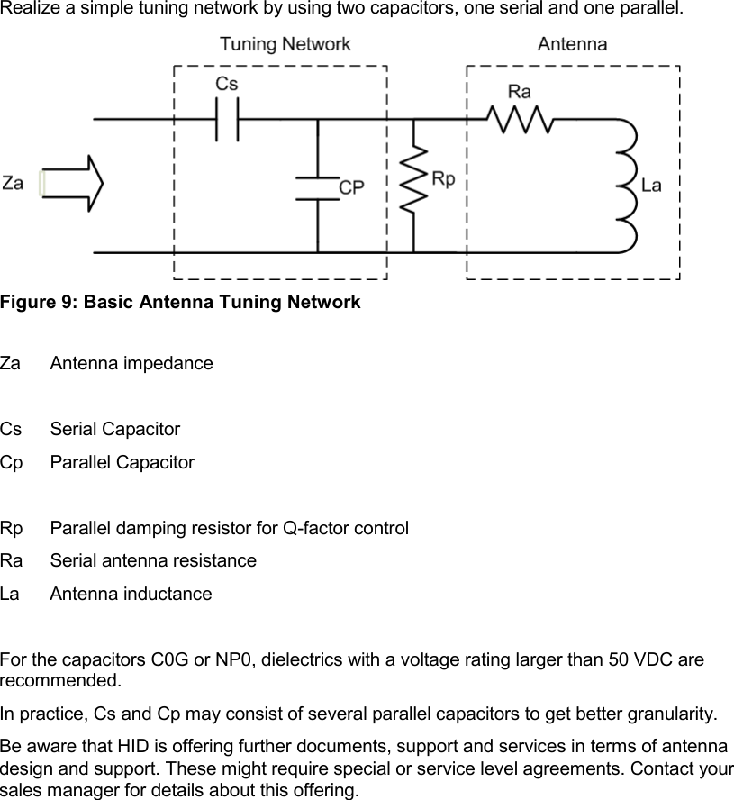
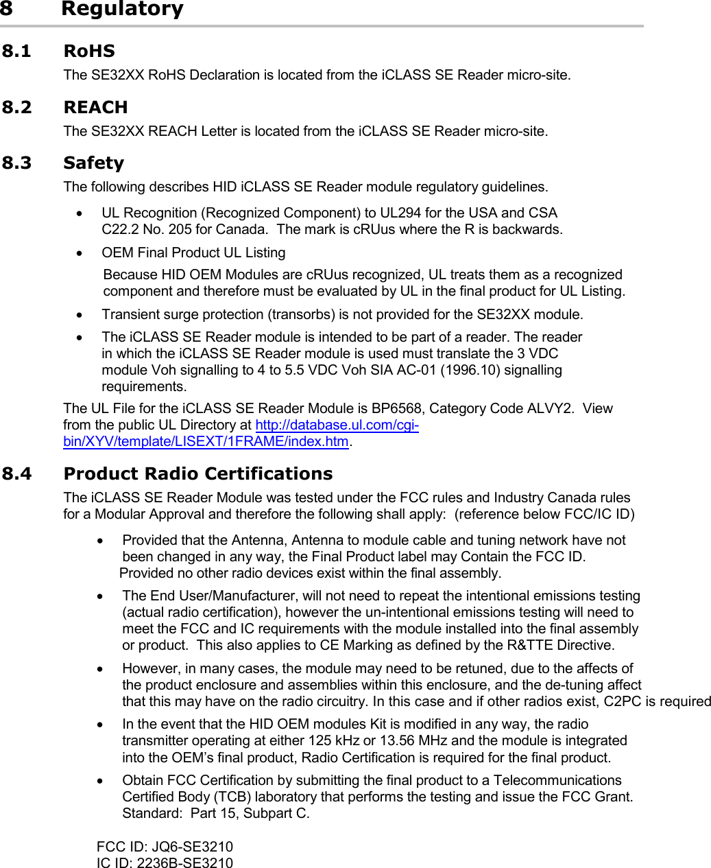
![iCLASS SE Reader Module Hardware Developer Guide, SE3200-902, Rev B.0 October 2012 Page 33 of 42 HID GLOBAL CONFIDENTIAL AND PROPRIETARY INFORMATION. Use and disclosure of this information is strictly restricted by the terms of the end user license agreement with HID Global Corporation. If you have received this information and are not an intended recipient or are not subject to or do not agree to be bound by the terms of the non-disclosure agreement, please immediately return this document to HID Global Corporation, 15370 Barranca Pkwy, Irvine, CA 92618-3106. 7.3.2 Typical Read Ranges with Standard Transponders The following read ranges are for indication only. The read range of a transponder may vary significantly depending on antenna size and quality factor. Table 17: 4090A10 HF Antenna with Standard ID1 Transponders shows tested card self-resonance frequency to provide an indication for the antenna design difference. For these read range tests, the transponder serial number was read. No cryptographic operations were performed. Table 17: 4090A10 HF Antenna with Standard ID1 Transponders Read Ranges Transponder / IC Type Manufacturer Form Factor Standard / Modulation Scheme SRF [MHz] Typical Read Range [mm] MIFARE Ultralight (MF0ICU1) NXP Semiconductors ID1 Card ISO/IEC14443 (Type A) 14.51 55 14.64 50 15.17 50 MIFARE Ultralight C (MF0ICU2) NXP Semiconductors ID1 Card ISO/IEC14443 (Type A) 14.12 40 MIFARE Classic (MF1S50) NXP Semiconductors ID1 Card ISO/IEC14443 (Type A) 14.04 55 14.81 50 15.83 40 MIFARE Classic (MF1S70) NXP Semiconductors ID1 Card ISO/IEC14443 (Type A) 15.22 45 MIFARE Classic (SLE66CL160S) Infineon Technologies ID1 Card ISO/IEC14443 (Type A) 15.28 50 15.34 40 MIFARE Plus X (MF1PLUSx0) NXP Semiconductors ID1 Card ISO/IEC14443 (Type A) 15.58 45 MIFARE DESFire (MF3ICD40) NXP Semiconductors ID1 Card ISO/IEC14443 (Type A) 14.94 40 15.37 45 15.50 40 MIFARE DESFire EV1 (MF3ICD21) NXP Semiconductors ID1 Card ISO/IEC14443 (Type A) 15.00 45 15.73 40 SLE55R16 Infineon Technologies ID1 Card ISO/IEC14443 (Type A) 15.05 40 15.68 35 SmartMX (P5CD072) NXP Semiconductors ID1 Card ISO/IEC14443 (Type A) 16.07 40 16.34 35 SmartMX (P5CD081) NXP Semiconductors ID1 Card ISO/IEC14443 (Type A) 16.85 20 CD21 ITSO Oberthur Card Systems ID1 Card ISO/IEC14443 (Type B) 15.21 20 15.34 20 iCLASS 32k HID Global ID1 Card ISO/IEC15693 13.63 100 13.86 80 14.14 70 iCLASS 16k HID Global ID1 Card ISO/IEC15693 13.67 95](https://usermanual.wiki/HID-Global/SE3210/User-Guide-1896779-Page-33.png)
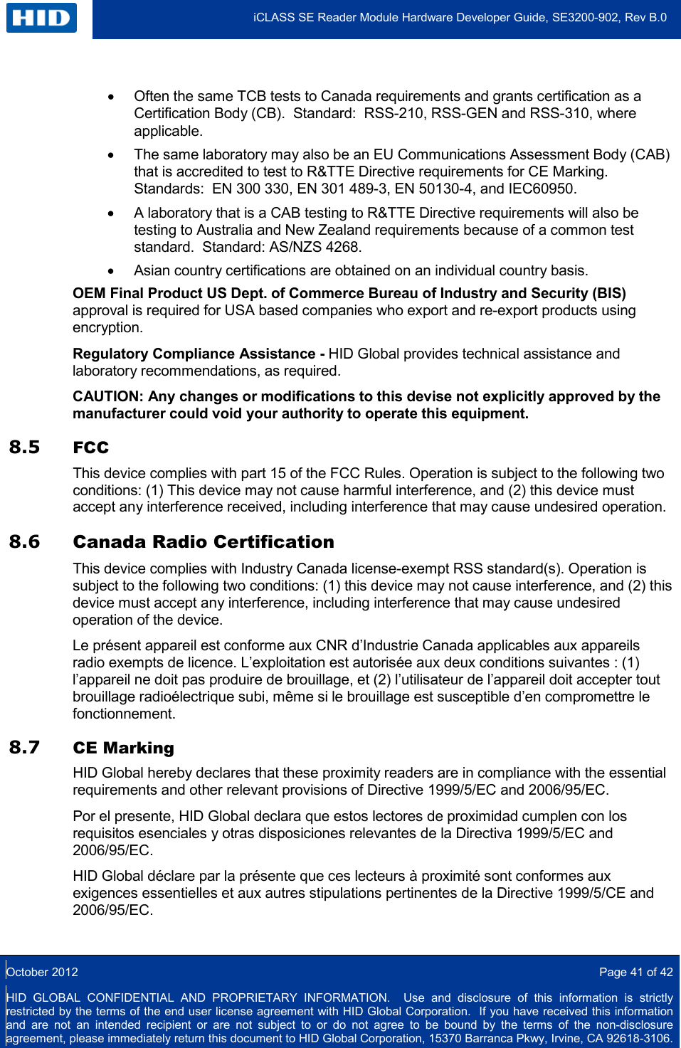
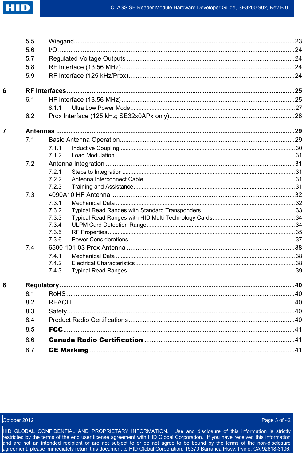
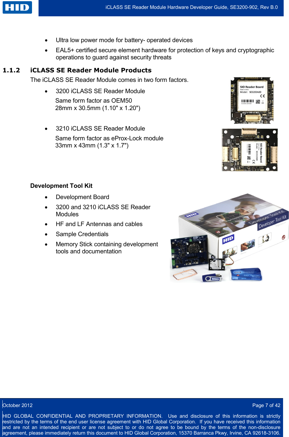
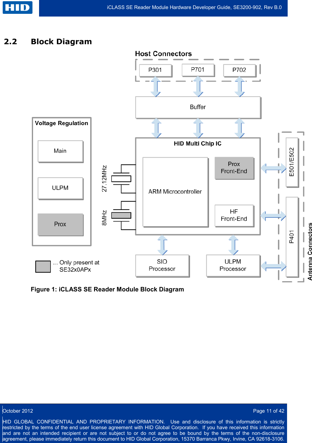
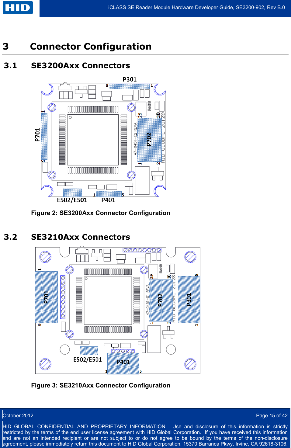
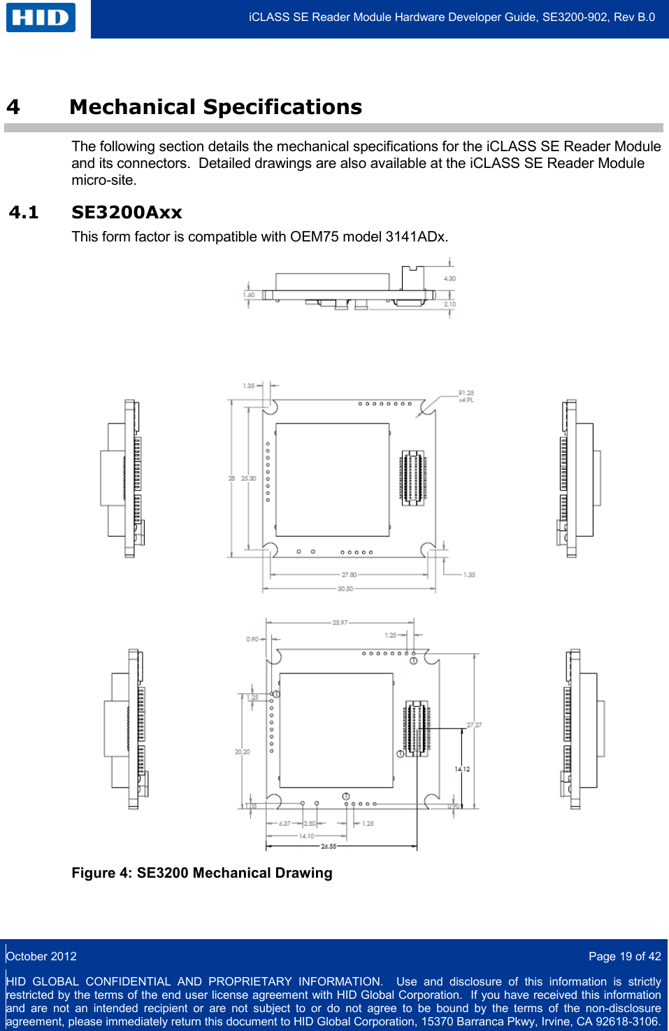
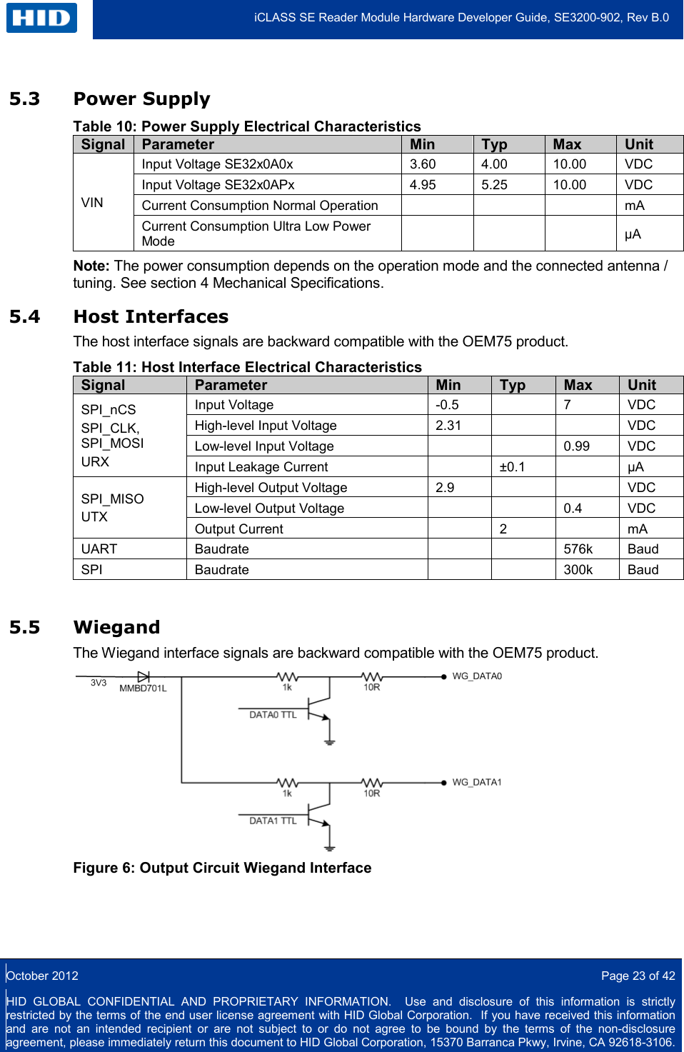
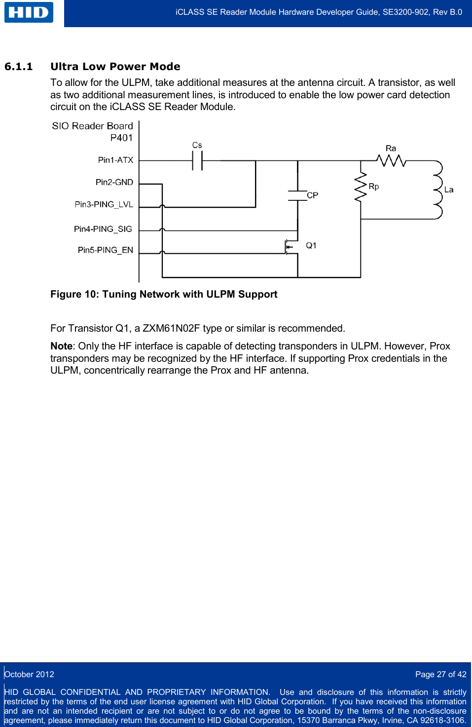
![Transponder / IC Type Manufacturer Form Factor Standard / Modulation Scheme SRF [MHz] Typical Read Range [mm] iCLASS 2k HID Global ID1 Card ISO/IEC15693 13.48 95 My-d vicinity plain (SRF55V02P) Infineon Technologies ID1 Card ISO/IEC15693 13.93 90 My-d vicinity secure (SRF55V10S) Infineon Technologies ID1 Card ISO/IEC15693 14.44 75 Tag-it HF-I Plus Texas Instruments ID1 Card ISO/IEC15693 13.74 70 ICODE SLI (SL2ICS20) NXP Semiconductors ID1 Card ISO/IEC15693 13.38 80 ICODE SLI-S (SL2ICS53) NXP Semiconductors ID1 Card ISO/IEC15693 13.68 120 LRi2K ST Microelectronics ID1 Card ISO/IEC15693 13.68 110 13.89 90 FeliCa RC-S962 Sony Corporation ID1 Card FeliCa 13.52 65 14.15 50 FeliCa RC-S915 Sony Corporation ID1 Card FeliCa 13.57 35 13.58 35 7.3.3 Typical Read Ranges with HID Multi Technology Cards For this read range tests the serial number of each individual HF chip inside the multi technology card was read. For Prox read ranges, see Section 7.4 6500-101-03 Prox Antenna. Note: Read range varies depending on the transponders antenna size, design, SRF and Quality. Table 18: Typical Read Ranges 4090A10 HF Antenna - HID Multi Technology Cards Card Type Manufacturer Standard / Modulation Scheme Chip Typical Read Range[mm] MIFARE / Prox HID Global ISO/IEC14443 (Type A) MIFARE 40 DESFire / Prox HID Global ISO/IEC14443 (Type A) DESFire 35 iCLASS / MIFARE / Prox HID Global ISO/IEC14443 (Type A) MIFARE 45 ISO/IEC15693 iCLASS 60 iCLASS / DESFire / Prox HID Global ISO/IEC14443 (Type A) DESFire 40 ISO/IEC15693 iCLASS 50 7.3.4 ULPM Card Detection Range The card detection range in Ultra Low Power Mode depends on the loading effect the transponder imposes on the iCLASS SE Reader Module’s antenna. That means that cards with lower loading effect will generally have a shorter detection range.](https://usermanual.wiki/HID-Global/SE3210/User-Guide-1896779-Page-34.png)
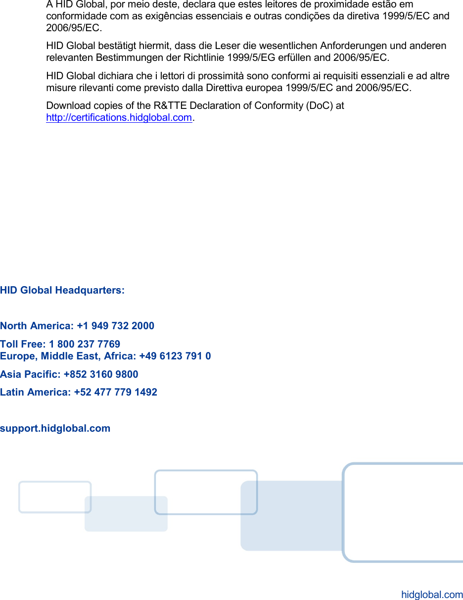
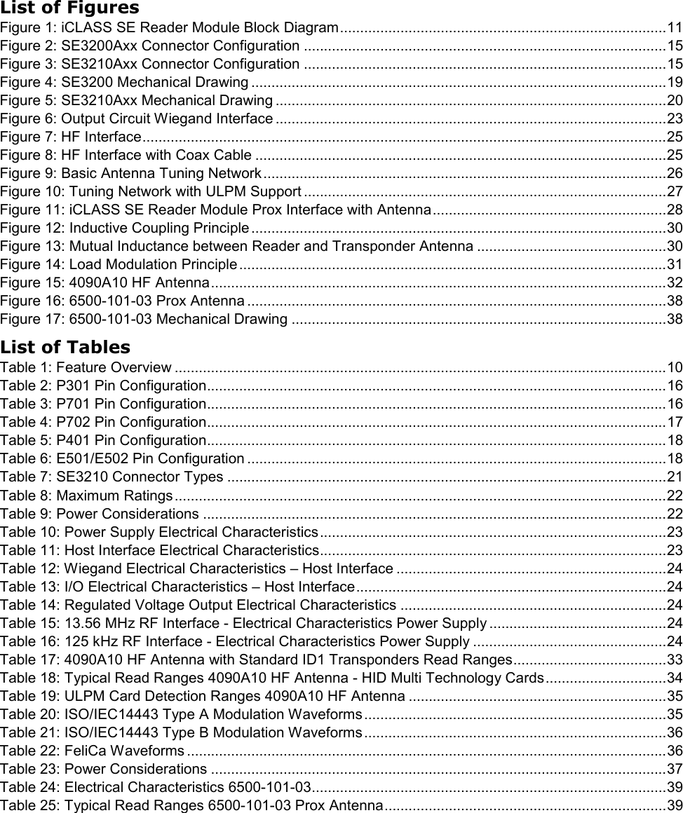
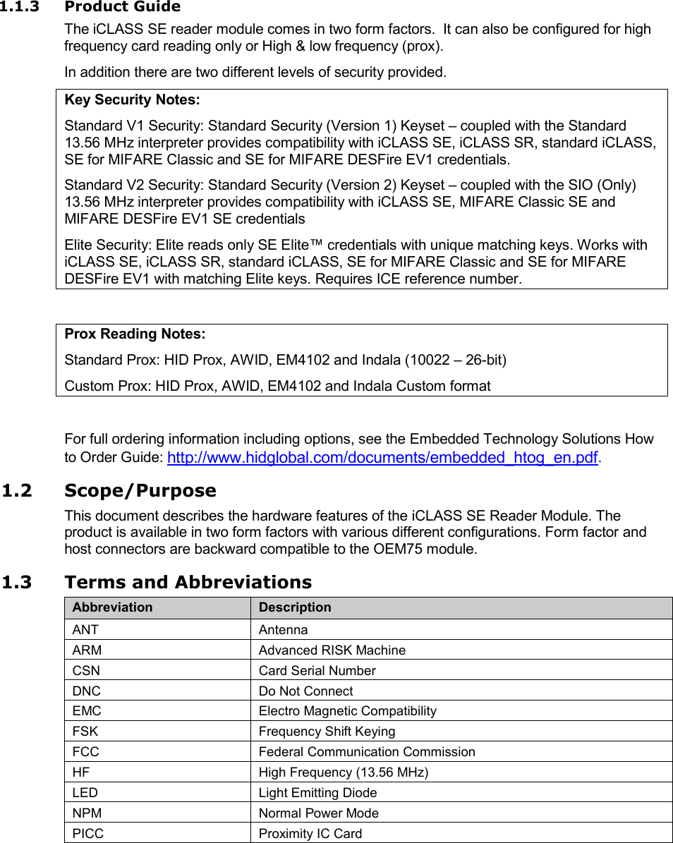
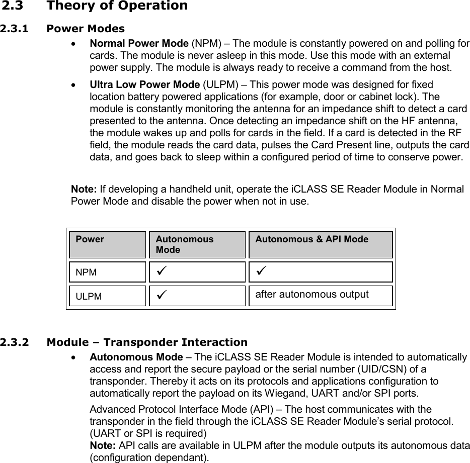
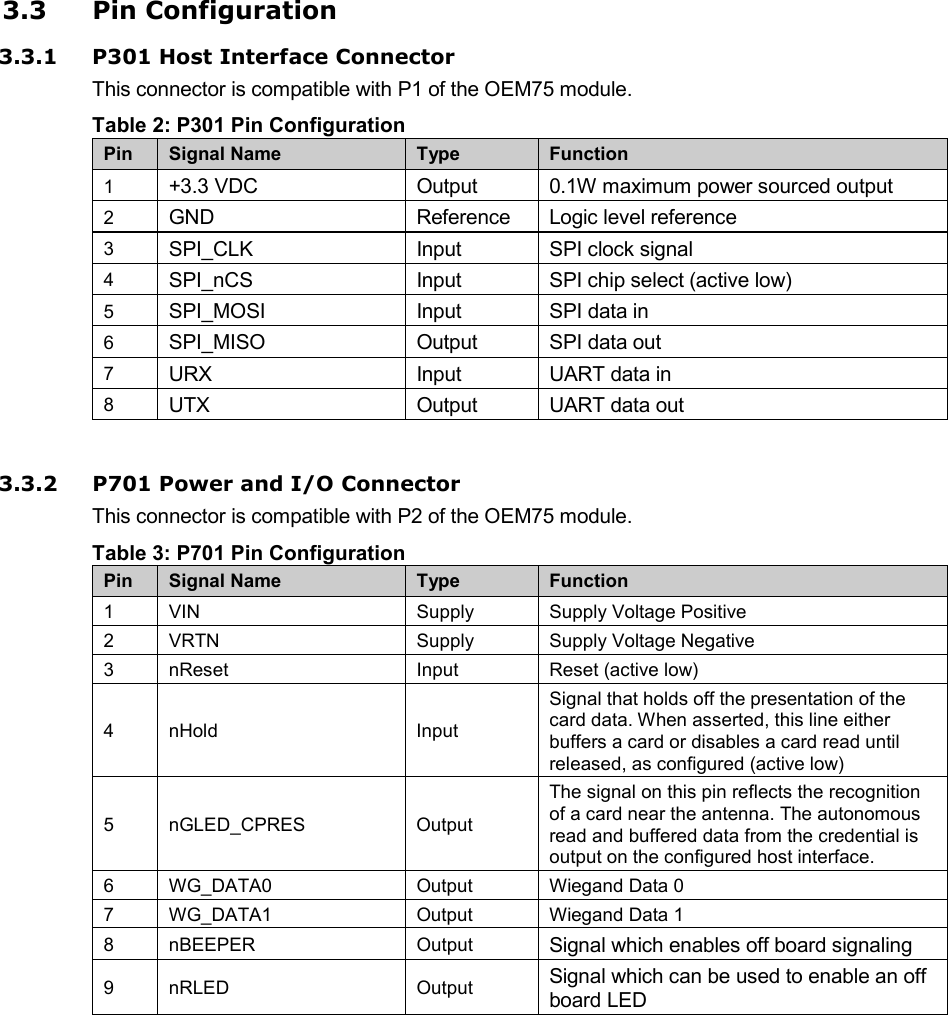
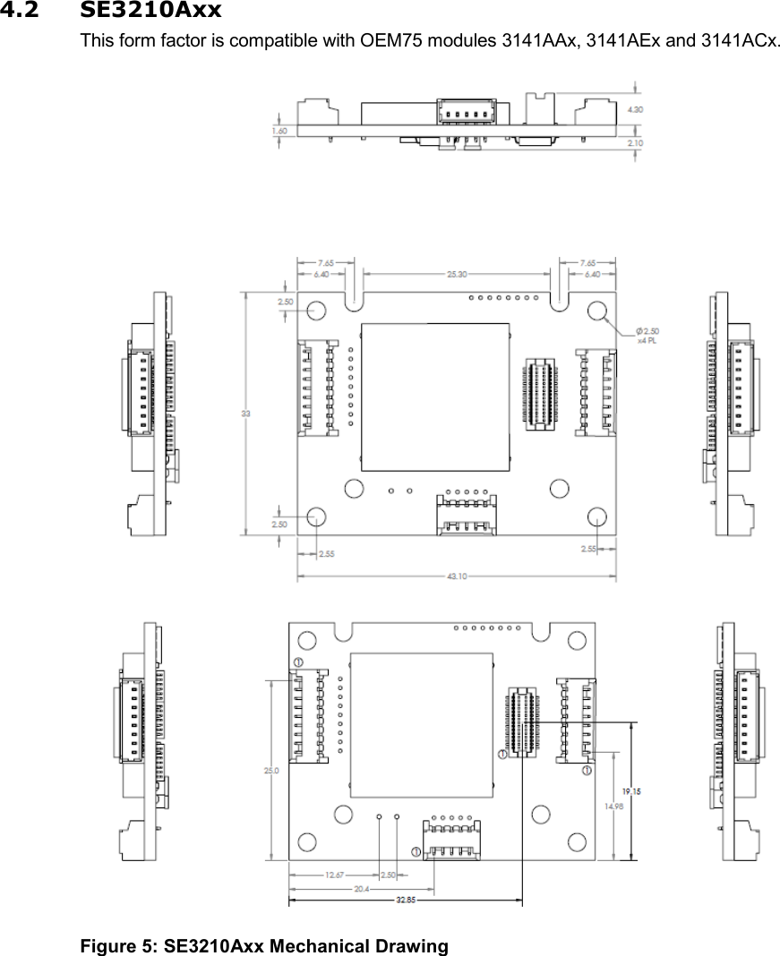
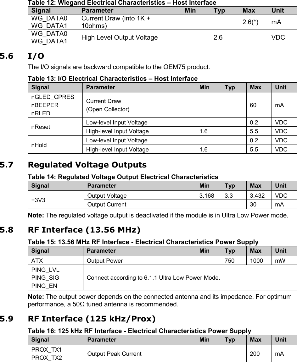
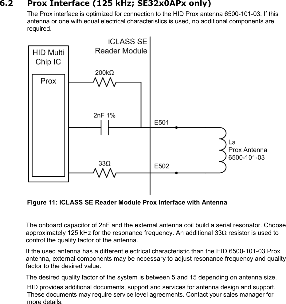
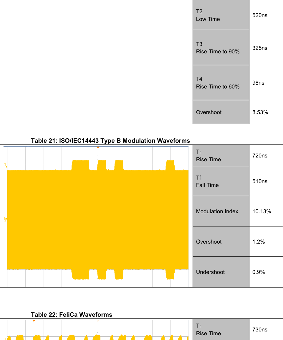
![iCLASS SE Reader Module Hardware Developer Guide, SE3200-902, Rev B.0 October 2012 Page 35 of 42 HID GLOBAL CONFIDENTIAL AND PROPRIETARY INFORMATION. Use and disclosure of this information is strictly restricted by the terms of the end user license agreement with HID Global Corporation. If you have received this information and are not an intended recipient or are not subject to or do not agree to be bound by the terms of the non-disclosure agreement, please immediately return this document to HID Global Corporation, 15370 Barranca Pkwy, Irvine, CA 92618-3106. The following table provides an overview of typical detection ranges with some transponders. Table 19: ULPM Card Detection Ranges 4090A10 HF Antenna Transponder / IC Type Manufacturer SRF[MHz] Typical Detection Range[mm] MIFARE Ultralight (MF0ICU1) NXP Semiconductors 14.51 55 MIFARE Classic (MF1S50) NXP Semiconductors 14.04 55 MIFARE DESFire (MF3ICD40) NXP Semiconductors 15.37 45 iCLASS 32k HID Global 13.63 90 FeliCa RC-S962 Sony Corporation 13.52 85 Note: If the card detection range exceeds the actual read range, the reader may wake up but not read the transponder successfully at this distance. 7.3.5 RF Properties Provided is an overview on the RF properties of the 4090A10 HF antenna in combination with the iCLASS SE Reader Module. The modulation waveforms were measured at a distance of 10mm. Parameters may vary per unit due to component tolerances. The compliance of the modulation waveforms is essential to ensure the interoperability with various transponders in the field. All measurements were performed in accordance to the ISO/IEC10373-6 standard. Note: The following graph shows that at distances smaller than 12mm, the detuning of the Reference PICC used for the measurement causes the field strength to decrease. Observe similar behavior with transponders that introduce a loading effect of similar magnitude. Table 20: ISO/IEC14443 Type A Modulation Waveforms T1 Pause Length 2.52µs 0 0.5 1 1.5 2 2.5 3 3.5 2 4 6 8 10 12 14 16 18 20 H[A/m] d[mm] 4090A10 Magnetic Field Strength H H](https://usermanual.wiki/HID-Global/SE3210/User-Guide-1896779-Page-35.png)
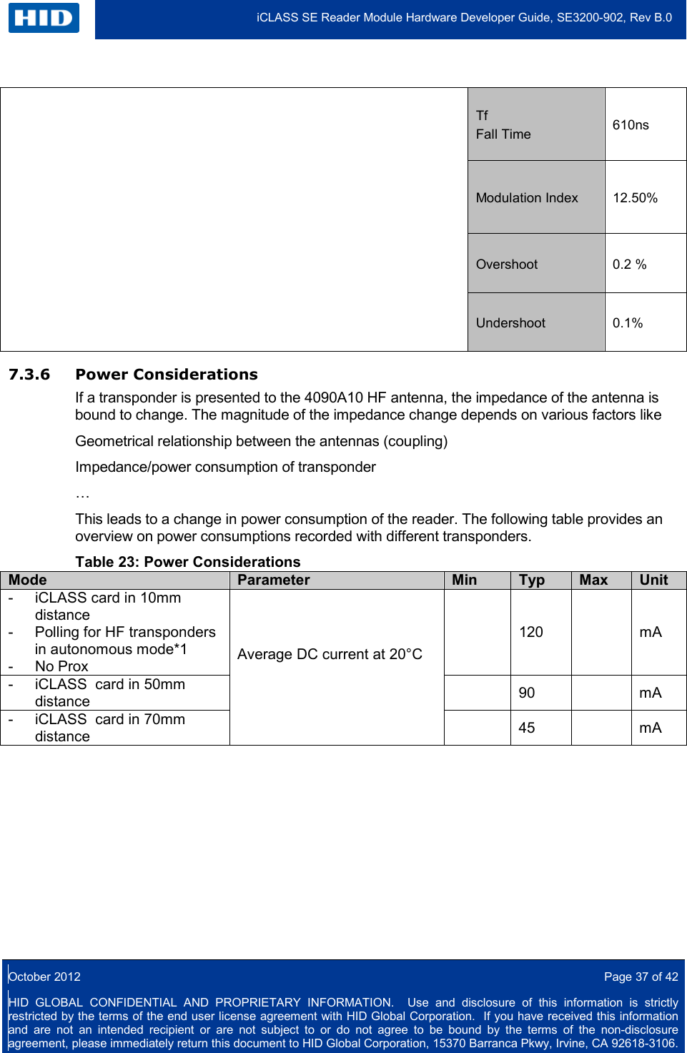
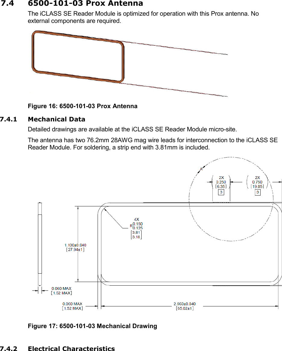
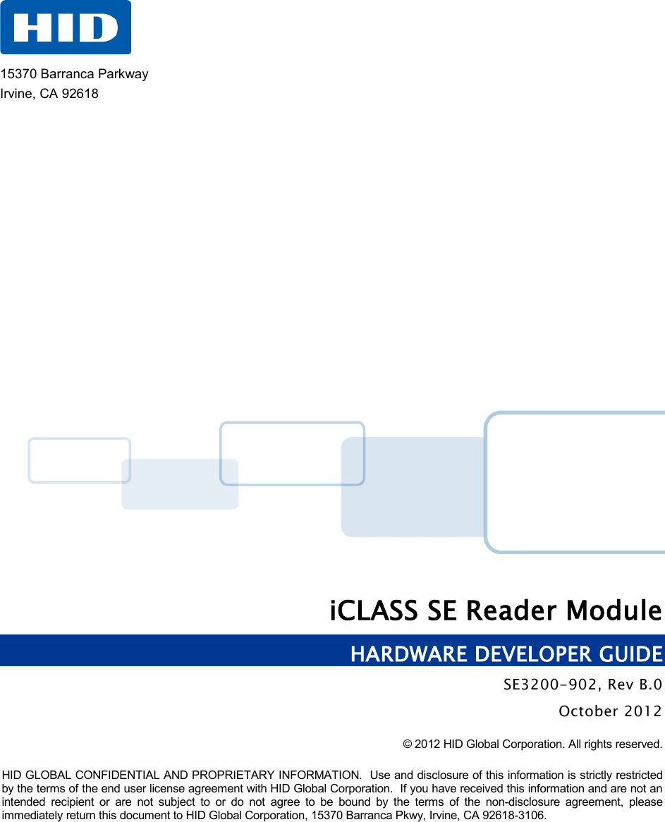
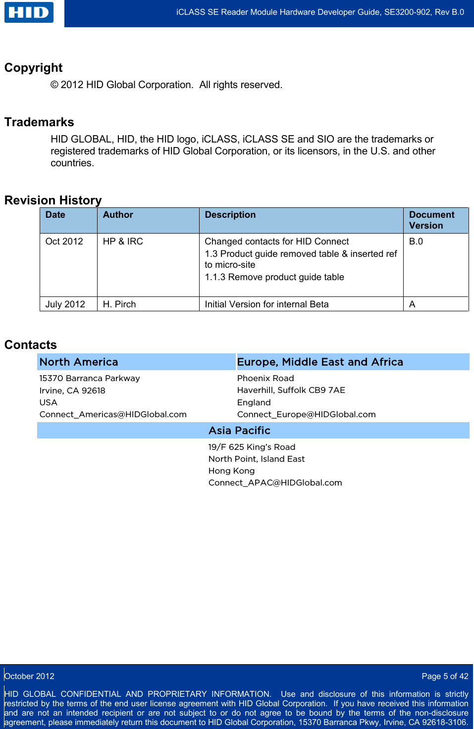
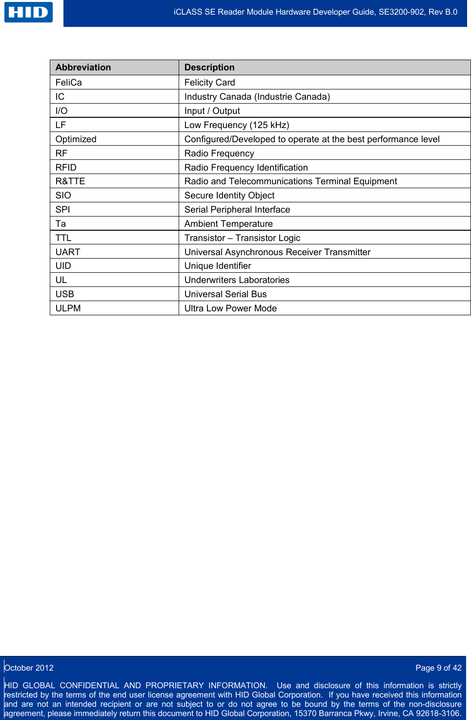
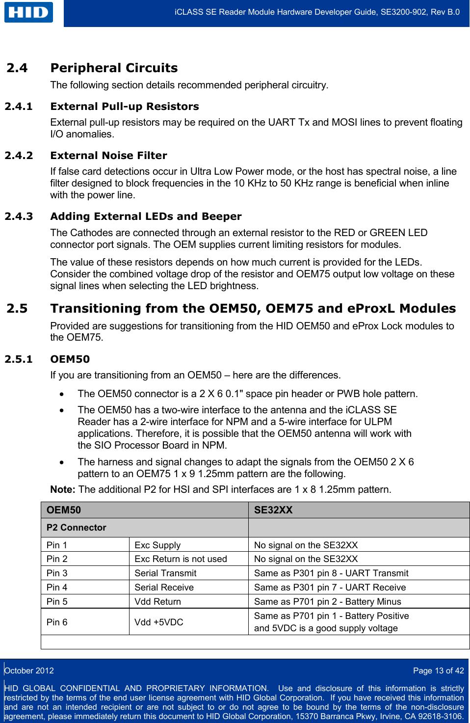
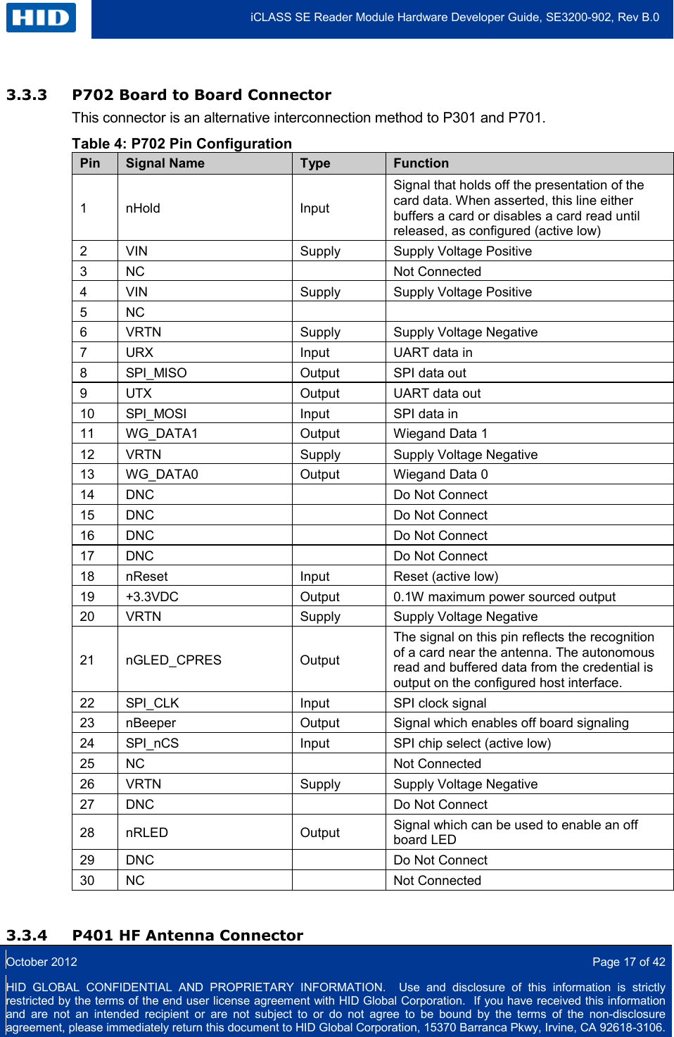
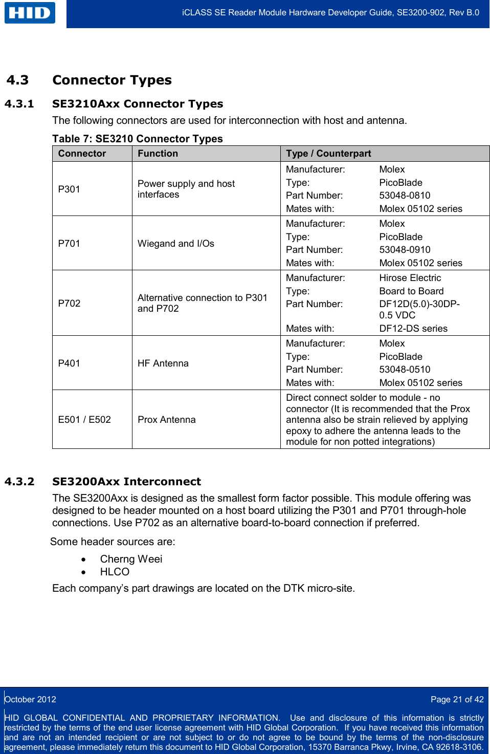
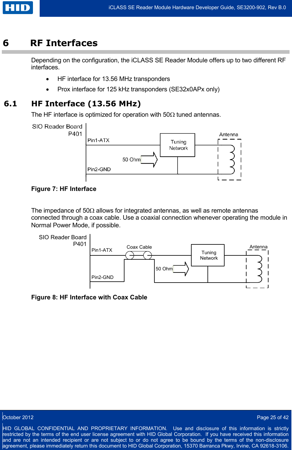
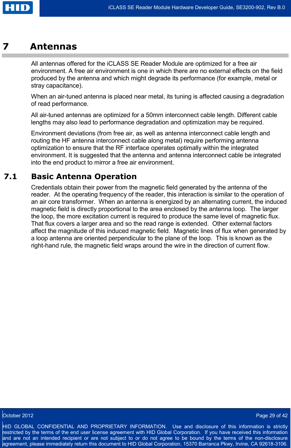
![iCLASS SE Reader Module Hardware Developer Guide, SE3200-902, Rev B.0 October 2012 Page 39 of 42 HID GLOBAL CONFIDENTIAL AND PROPRIETARY INFORMATION. Use and disclosure of this information is strictly restricted by the terms of the end user license agreement with HID Global Corporation. If you have received this information and are not an intended recipient or are not subject to or do not agree to be bound by the terms of the non-disclosure agreement, please immediately return this document to HID Global Corporation, 15370 Barranca Pkwy, Irvine, CA 92618-3106. Table 24: Electrical Characteristics 6500-101-03 Parameter Measurement Frequency Typ Unit Number of turns 89 - DC Resistance 33 Ω SRF 1 MHz Inductance 1kHz 800 µH Impedance 50kHz 29+j248 Ω 100kHz 31+j489 Ω 500kHz 50+j2674 Ω 7.4.3 Typical Read Ranges The measured read ranges are indications only. Read range varies due to transponder antenna size and quality, as well as environmental effects. Table 25: Typical Read Ranges 6500-101-03 Prox Antenna Transponder Modulation Scheme Typical Read Range [mm] HID Prox FSK 40 HID DuoProx II FSK 60 MIFARE / HID Prox Combo Card FSK 60 Indala Prox PSK 55](https://usermanual.wiki/HID-Global/SE3210/User-Guide-1896779-Page-39.png)