HIGH TEK HARNESS ENTERPRISE WLAN01 802.11b mini-PCI Card User Manual Userguide
HIGH-TEK HARNESS ENTERPRISE CO., LTD. 802.11b mini-PCI Card Userguide
Revised Installation Guide

1
HTKWLAN01 11Mbps MINIPCI WLAN Card
User’s Guide
A. Introduction
The HTKWLAN01 Wireless Local Area Network(WLAN) MINIPCI Card enables
high-speed access without wires to network assets. This WLAN card uses the IEEE 802.11b
protocol to enable communications between the host and the other computers, using the 2.4GHz
ISM Radio Band for the communications medium. It supports the IEEE 802.11b network
specification for Direct Sequence Spread Spectrum (DSSS) signaling, providing data rates of 1, 2,
5.5, 11Mbps. The host computer uses the HTKWLAN01 WLAN card for communications in the
same way that it would use an Ethernet adapter.
B. Features
Support for 11, 5.5, 2 and 1 Megabit Per Second (Mbps) Data Rate
Supports the IEEE 802.11 Direct Sequence Specification
Driver Supports Microsoft Windows 95, 98, 2000, XP
Provides Wireless Data Communication at Full Ethernet Speed
Designed to Fully Support Minipci Type 3B Defined Mechanical and Environment Stress
Conditions
C. Specifications
C. 1 General Specifications
?? Targeted Standard ………………………..IEEE 802.11b
?? Data Rate…………………………………1 Mbps DBPSK
2 Mbps DQPSK
5.5Mbps CCK
11Mbps CCK

2
?? Range……………………………………..Up to 100m, Indoor
Up to 300m, Outdoor
?? Frequency Range…………………………2412~2484MHz
?? Step Size…………………………………..1MHz
?? IF Frequency………………………………374.25MHz
?? IF Bandwidth………………………………17MHz
?? Rx/Tx Switching Speed…………………….2us(Typ.)
?? Operating Voltage…………………………..3.0~3.6 VDC
?? Operating Temperature Range……………...0℃~70℃
?? Storage Temperature Range…………………-20℃~85℃
?? Mechanical………………………………….Type 3B Minipci Card
?? Antenna Interface……………………………I-pex, 50Ω
C. 2 Receive Specifications
?? Sensitivity…………………………………….-83dbm(Typ.)
?? RX Supply Current……………………………300mA(Typ.)
C. 3 Transmit Specifications
?? Output Power………………………………….+14dbm(Typ.)
?? Transmit Spectral Mask…………………-30dBc(Typ.) at First Side-Lobe
?? Supply Current…………………………………450mA(Typ.)
3
D. Installation Drivers
D. 1 Installation of HTKWLAN01 Windows Drivers
Step 1. With the HTKWLAN01 MINIPCI WLAN Card insert into the MINIPCI slot where is
inside your computer, and then boot your computer under Microsoft Windows 95,
98,2000 or XP.
Step 2. Once your computer system has booted and to show a message that detecting a new
device, in the same time insert the Disk what is HTKWLAN01’s Driver for Windows
into the CD-ROM drive.
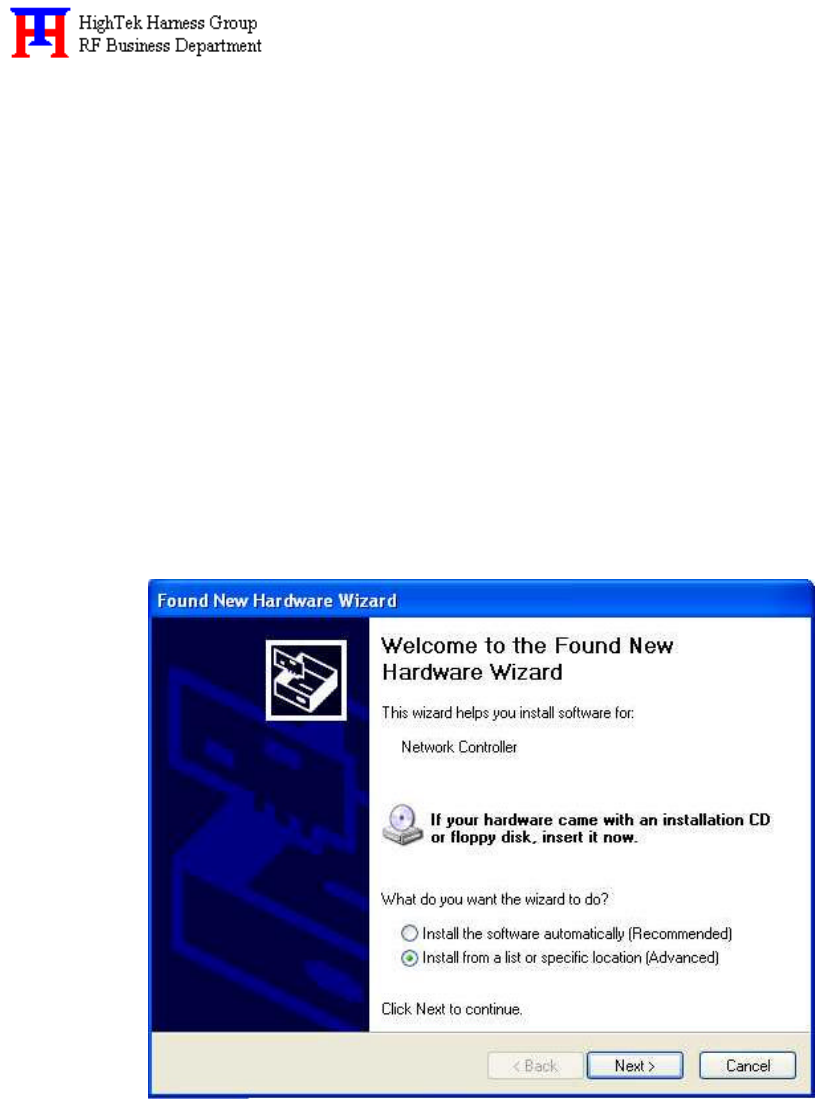
Step 3. Select “Install from a list or specific location (Advanced)”, and then click “Next” to
continue, as shown in the above-mentioned illustration.
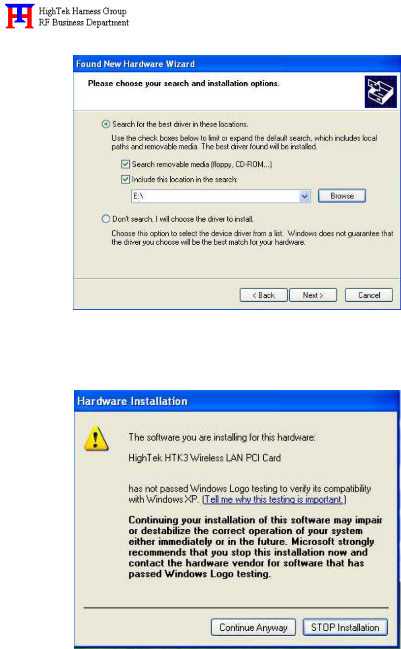
Step 4. Browse correct path for driver disk, and then click “Next”, as shown in the following
illustration.
4
Step 5. Click “Continue Anyway”, as shown in the following illustration.
5
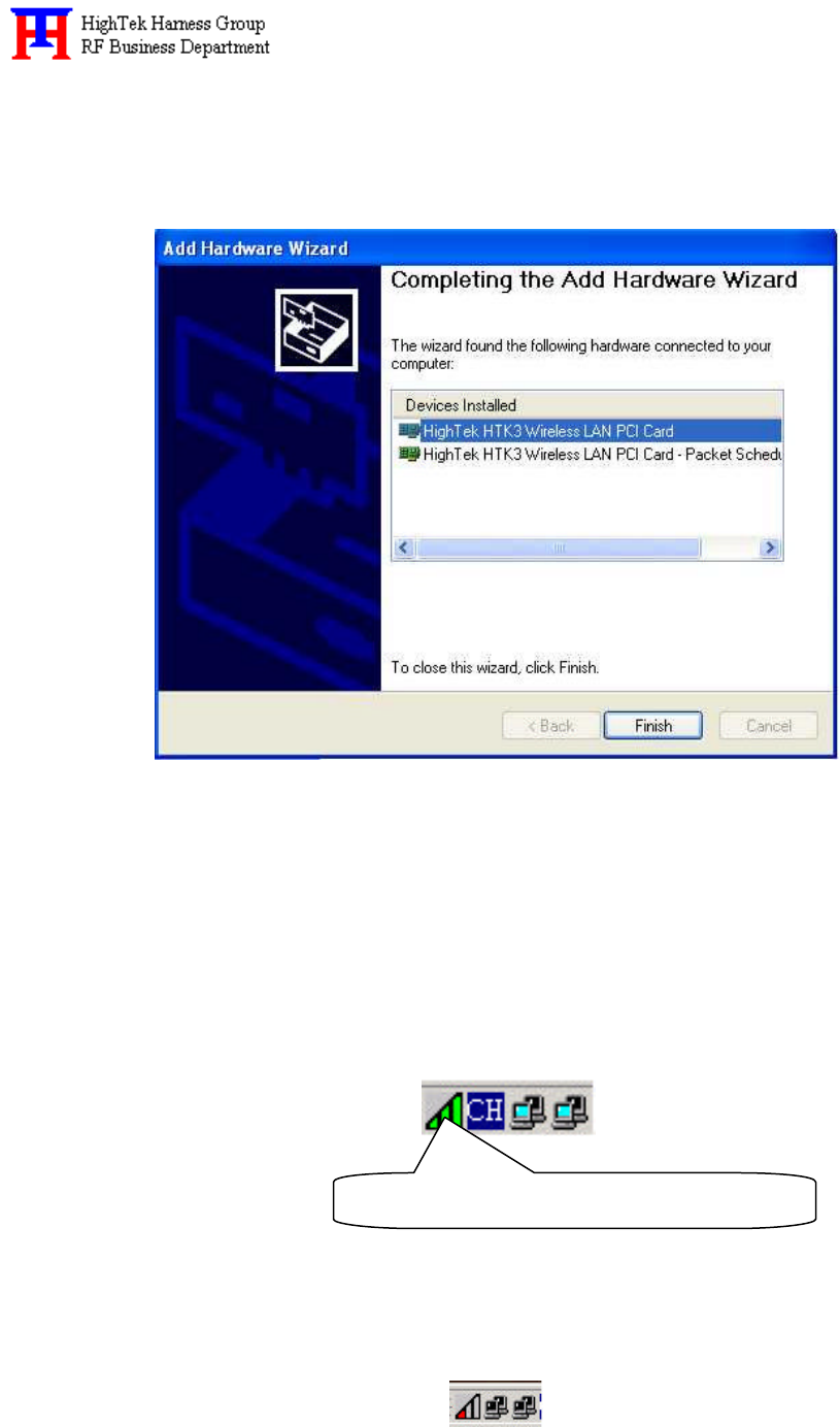
Step 6. Select “High Tek HTK3 Wireless LAN PCI Card”, and then click “Finish”, as shown in
the following illustration. The driver installation is completed.
D. 2 Operation
After you installed HTKWLAN01 driver completely, both the driver and the Configuration
Utility are installed on your computer, it’s icon appears in the System Tray in the bottom right
corner of your computer.
The color and layers are to shine behind the High-Tek(HTK) logo indicates the link status.
?? Red and one layer to shine indicating no or very poor link quality.
HTKWLAN01 Configuration Utility Icon
6
?? Yellow and two layers to shine indicating a usable but weak link.
?? Green and all layers to shine indicating a good or excellent link.
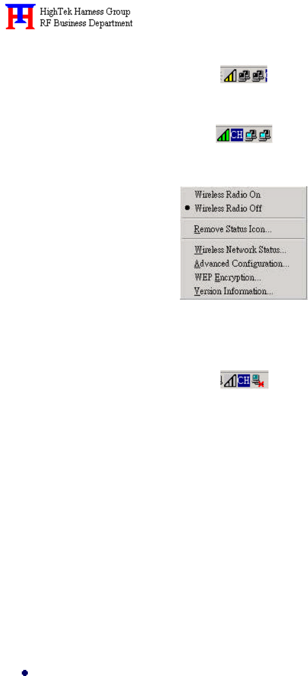
?? Clicking on the System Tool Tray Icon displays a menu similar to the following illustration:
The first two items in the menu let you turn the wireless radio on or off. When the wireless
radio is turned off, the following icon appears in the system tray.
D. 3 Starting the Configuration Utility
You can launch the Configuration Utility by clicking on the Configuration Utility icon and
selecting one of the last four commands in the pop-up menu. The Configuration Utility consists of a
window with four tabs: Status, Configuration, Encryption, and About
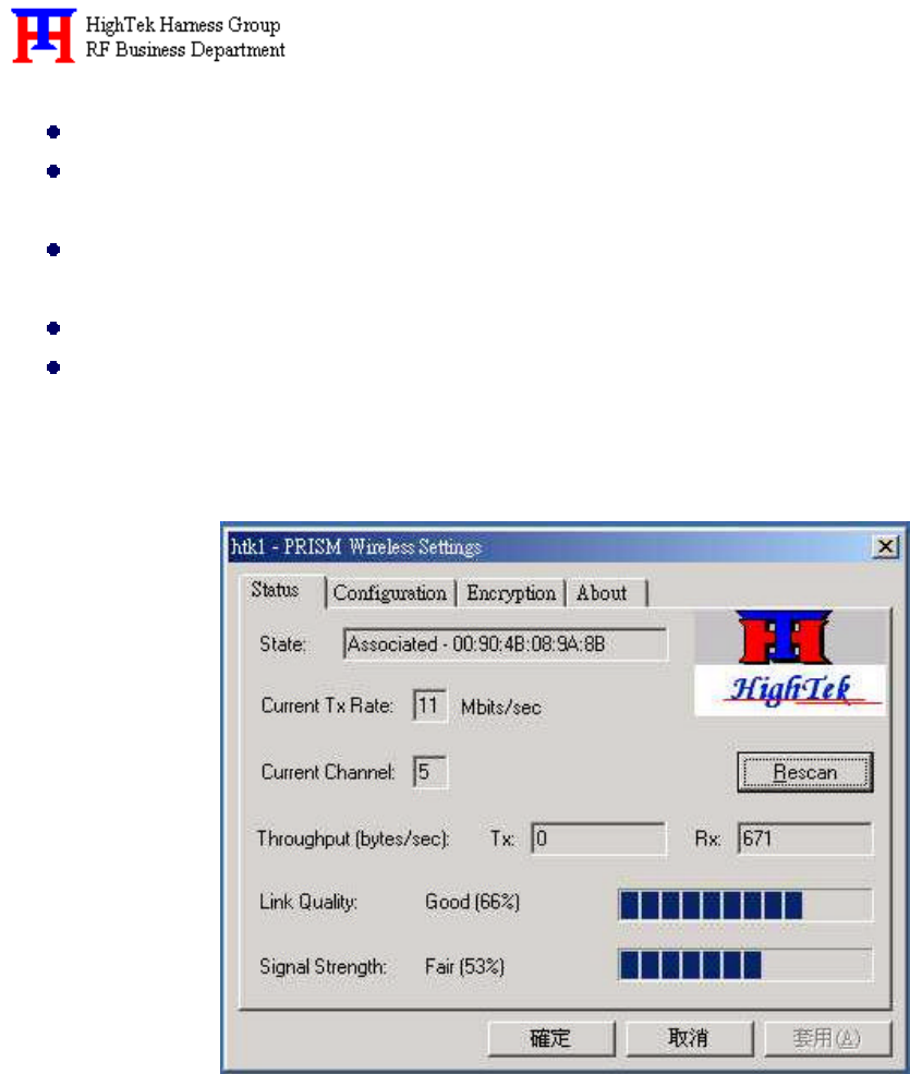
Status Menu:
The status menu displays information on the current status of your connection to the WLAN.
You can display this menu by choosing the Wireless Network Status… command from the pop-up
menu, or by clicking on the Status tab when the Configuration Utility is displayed on your
computer.
The fields in this menu provide the following information:
State: shows the association state of your computer with the wireless LAN. When operating
in Infrastructure mode, this field shows the MAC address of the Access Point with
which you are communicating. When operating in Peer-to Peer mode, this field
shows the virtual MAC address used by computers participating in the AdHoc
7
network.
Current Tx Rate: shows the current transmit rate of the current association.
Current Channel: shows the channel on which the connection is made. In Infrastructure
mode, this number changes as the radio scans the available channels.
Throughput: shows the short term transmit and receive throughput in bytes/second, and is
continuously updated.
Link Quality: is based on the quality of the received signal of Access Point beacon.
Signal Strength: is based on the received signal strength measurement of the baseband
processor of the Beacon signal.
You can click the Disable Radio button to turn off the wireless radio. When you click this
button, the State field indicates that the radio has been turned off and remaining fields in this
window display either a zero or Not Applicable. Click this button again to turn the radio back on.
You can click the Rescan button to force the radio to rescan all available channels. If your link
quality or signal strength is poor, rescanning can be used to push the radio off a weak Access Point
and search for a better with another Access Point.
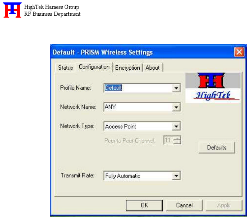
Configuration Menu:
The Configuration menu lets you specify the operating parameters for your HTK WLAN
Interface adapter. You can display this menu by choosing the Advanced Configuration ... command
from the pop-up menu, or by clicking on the Configuration tab when the Configuration Utility is
8
displayed on your computer.
Setting the Profile:
A profile is a named set of operating parameters for your HTK WLAN Interface adapter. The
Profile Name: field lets you set values for all parameters by selecting a previously defined profile.
Click the down arrow at the right of this field to display the available profiles for your HTK
WLAN Interface adapter.
You will always have at least one profile, named Default. Initially, this profile contains the
parameters configured at installation. You can modify this profile at any time after the installation.
After changing parameters, you can save them in the profile named in this field by clicking the
Apply button in the Configuration Utility panel.
You can also create additional profiles by typing a name in the Profile Name: field. When you
change the name in this field and then click the Apply button, the Configuration Utility uses the
current parameters for your adapter to create a separate profile. You can then switch between
profiles by clicking the down arrow at the right of the Profile Name: field, selecting a profile from
the drop-down list, and clicking the Apply button.
The following example describes a situation in which you would want to create multiple
profiles. Suppose that you use the wireless LAN at your work, but you also have a network in your
home (with a wireless Access Point) for sharing an internet connection and a printer between
several computers. Suppose also that you have another office within your business which also has

9
WLAN capability, but which is configured differently than your main office.
In this situation, you can create a different profile for each of these three environments. Each
profile specifies the parameters used on a single network. Moving from one location to another, you
only need to apply the appropriate profile to be able to participate in the local network.
Network Name:
Officially, in wireless networks the network name is known as the SSID (Service Set
IDentifier), and is used by Access Points and stations to identify a wireless LAN. Your HTK
WLAN Interface adapter scans the available channels looking for an Access Point or another station
which has specified this same SSID. It then attempts to associate with these Access Points or
stations to form a wireless LAN. To change the SSID, simply highlight it, type the new SSID, and
click the Apply button. In typical infrastructure applications a company will use a single SSID for
all Access Points. If the radio is scanning and cannot find a channel when an Access Point is known
to be in range, verify that the Network Name is set correctly.
Network Type:
The HTK WLAN Interface adapter can operate in one of two types of networks, which are
specified in the Network Type: field of the Configuration menu. Clicking the down arrow at the
right of this field displays the available types.
Peer-to-Peer: IEEE 802.11, the standard on which the WLAN protocol is based, defines two modes
to handle two separate needs. The first, called AdHoc (or IBSS) mode, is used when
two or more wirelessly-enabled PCs wish to exchange data directly, without an
Access Point. In this case the PCs can establish a peer-to-peer network in which they
are the only members and over which they can exchange data. To exchange data,
each computer participating in the AdHoc network must also specify the same
Network Name and Channel in this menu.
Access Point: The second mode defined by the IEEE 802.11 standard is called infrastructure mode,
and is the primary application for WLAN operation. In this mode all data on the
wireless network is directed to an Access Point, which then routes the data to the
appropriate wireless station. The Access Point may also be configured to allow data
to be bridged from the wireless network to wired networks.To participate in a
wireless LAN in infrastructure mode, every station and Access Point must specify
the same Network Name. In infrastructure mode, all available channels are scanned
for traffic, so there is no need to specify a channel.
Selecting the Peer-to- Peer Channel: When communicating in a peer-to-peer network, you may
specify a channel on which you prefer communications to take place. To specify a

10
channel, click the up or down arrow at the right of the Peer-to-Peer Channel field
until the channel you want to set appears, and then click the Apply button. Note that
this is not necessarily the channel on which peer-to-peer communications will be
established. If the IBSS network names (SSID) are the same for each node in the
peer-to- peer network and they each have different preferred channels, a network can
still be established. In this case, if it cannot find a network with the specified
network name on the preferred channel, a station will scan other channels until it
finds a peer-to-peer network on which to communicate.
Transmit Rate:
The Transmit Rate field specifies the rate at which the radio in your HTK adapter transmits
and receives data. You can view the available rates by clicking the down arrow at the right of the
Transmit Rate field. The transmit is normally set to Fully Automatic, in which case your HTK
adapter chooses the highest available rate providing reliable communications based on the
capabilities of the Access Point or station with which it communicates and on the received signal
quality.
Other selection in this field let you specify a fixed transmit rate; the rates available depend on
the capabilities of your adapter. To change the Transmit Rate, click the down arrow at the right of
the field, highlight the rate you want to set, and click the Apply button. Under most conditions, you
should choose Fully Automatic as the transmit rate. In general, fixed rates are used only in test
environments.
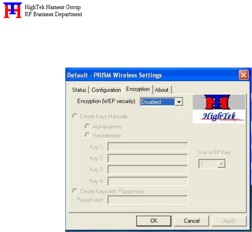
Encryption Menu:
The Encryption menu lets you enable encryption and set the encryption keys. To see the
available encryption methods, click the down arrow at the right of the Encryption (WEP security)
field.
There are two encryption methods available. The IEEE 802.11 specification defines Wired
Equivalent Privacy (WEP) using a 64-bit key. This capability was extended by the industry to allow
a 128-bit key. If you specify an encryption method, you will only be able to communicate with
Access Points and stations that use the same encryption method and keys.
Disabling Encryption: To disable encryption, click the down arrow at the right of the Encryption
field, select Disabled, and click the Apply button.
Enabling Encryption: To enable encryption, click the down arrow at the right of the Encryption
field, select either 64 bit or 128 bit, and click the Apply button. After
enabling an encryption method, you must then specify encryption keys, as
described in the following sections.
11
Creating Encryption Keys Manually:
When you specify either 64-bit or 128-bit encryption, the Configuration Utility selects Create
Keys Manually.
The utility allows you to enter keys as either alphanumeric or hexadecimal characters. When
you click one of these buttons, the cursor appears in the field for Key 1. For 64-bit encryption, you
must type exactly 5 alphanumeric or 10 hexadecimal characters in each of the four key fields; for
128-bit encryption, you must type exactly 13 alphanumeric or 26 hexadecimal characters. You then
click the Apply button to create your encryption keys. After you click the Apply button, the
Configuration Utility uses asterisks to mask your keys.
The Use WEP Key field lets you specify which of the four encryption keys you use to transmit
data on your wireless LAN. You can change the default key by clicking on the down arrow at the
right of this field, selecting the number of the key you want to use, and then clicking the Apply
button. As long as the Access Point or station with which you are communicating has the same key
in the same position, you can use any of the keys as the default.
Creating Encryption Keys Using a Passphrase:
To create encryption keys using a passphrase, click the radio button next to Create Key with
Passphrase and type a character string in the Passphrase field. As you type, the Configuration Utility
displays asterisks to mask your passphrase and uses an algorithm to generate four keys used for
encryption.
12
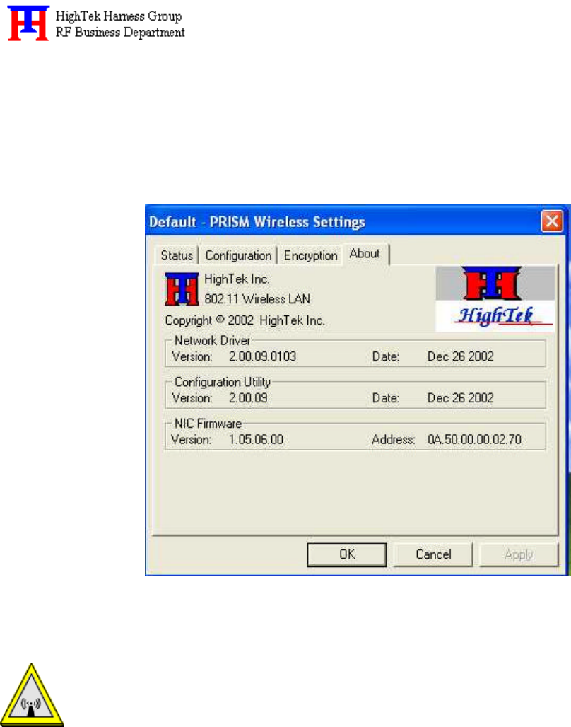
About Menu:
The About menu provides information on the version of the Network Driver, the Configuration
Utility, and the firmware in the HTK WLAN Interface adapter. You can display this menu by
choosing the Version Information... command from the pop-up menu, or by clicking on the About
tab when the Configuration Utility is displayed on your computer.
Warning: Changes or modifications to this unit not expressly approved by the party
responsible for compliance could void the user authority to operate the
equipment.
This device complies with Part 15 of the FCC Rules. Operation is subject
to the following two conditions: (1) this device may not cause harmful
interference, and (2) this device must accept any interference received,
including interference that may cause undesired operation.
The users manual or instruction manual for an intentional or unintentional

13
radiator shall caution the user that changes or modifications not expressly
approved by the party responsible for compliance could void the user’s
authority to operate the equipment.
NOTE: This equipment has been tested and found to comply with the limits for a
Class B digital device, pursuant to Part 15 of the FCC Rules. These limits
are designed to provide reasonable protection against harmful interference
in a residential installation. This equipment generates, uses and can radiate
radio frequency energy and, if not installed and used in accordance with the
instructions, may cause harmful interference to radio communications.
However, there is no guarantee that interference will not occur in a
particular installation. If this equipment does cause harmful interference
to radio or television reception, which can be determined by turning the
equipment off and on, the user is encouraged to try to correct the
interference by one or more of the following measures:
??Reorient or relocate the receiving antenna.
??Increase the separation between the equipment and receiver.
??Connect the equipment into an outlet on a circuit different from that to
which the receiver is needed.
??Consult the dealer or an experienced radio/TV technician for help.
CAUTION:
1. To comply with FCC RF exposure compliance requirements, a separation distance of
at least 20 cm must be maintained between the antenna of this device and all persons.
2. This Transmitter must not be co-located or operating in conjunction with any other
antenna or transmitter
This device is intended only for OEM integrators under the following conditions:
1) The antenna must be installed such that 20 cm is maintained between the antenna and users. For

14
laptop installations, the antenna must be installed to ensure that the proper spacing is maintained in
the event the users places the device in their lap during use (i.e. positioning of antennas must be
placed in the upper portion of the LCD panel only to ensure 20 cm will be maintained if the user
places the device in their lap for use) and
2) The transmitter module may not be co-located with any other transmitter or antenna.
As long as the 2 conditions above are met, further transmitter testing will not be required. However,
the OEM integrator is still responsible for testing their end-product for any additional compliance
requirements required with this module installed (for example, digital device emissions, PC
peripheral requirements, etc.).
IMPORTANT NOTE: In the event that these conditions can not be met (for example certain laptop
configurations or co-location with another transmitter), then the FCC authorization is no longer
considered valid and the FCC ID can not be used on the final product. In these circumstances, the
OEM integrator will be responsible for re-evaluating the end product (including the transmitter) and
obtaining a separate FCC authorization.
End Product Labeling
This transmitter module is authorized only for use in devices where the antenna may be installed
such that 20 cm may be maintained between the antenna and users (for example access points,
routers, wireless ASDL modems, certain laptop configurations, and similar equipment). The
final end product must be labeled in a visible area with the following: "Contains TX FCC ID:
{Q2EWLAN01 }".
RF Exposure Manual Information That Must be Included
The users manual for end users must include the following information in a prominent location
"IMPORTANT NOTE: To comply with FCC RF exposure compliance requirements, the antenna used
for this transmitter must be installed to provide a separation distance of at least 20 cm from all persons
and must not be co-located or operating in conjunction with any other antenna or transmitter."
Additional Information That Must be Provided to OEM Integrators
The end user should NOT be provided any instructions on how to remove or install the device.

15
Ambassador in U.S.A
Company: Everex Communications, Inc.
Contact: Mrs. Su-Jean Chen
Address: 5020 Brandin Court,
Fremont, CA 94538
U.S.A.
Tel: +1-510-6832000 Ext.108
Direct: +1-510-6832891
Fax: +1-510-6832893