HIGH TEK HARNESS ENTERPRISE WLAN02 802.11b Mini-PCI Card User Manual HTKWLAN02Userguide
HIGH-TEK HARNESS ENTERPRISE CO., LTD. 802.11b Mini-PCI Card HTKWLAN02Userguide
UserManual.wiki
>
HIGH TEK HARNESS ENTERPRISE
>
WLAN02 User Manual
Manual
Navigation menu
Upload a User Manual
Namespaces
Wiki Guide
HTML
PDF
Info
Views
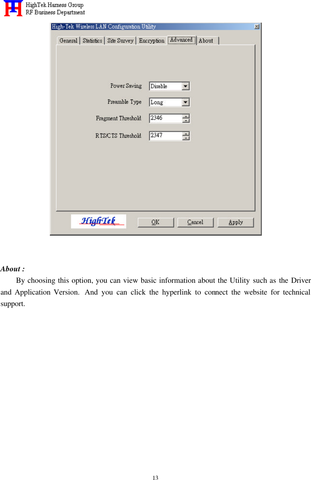
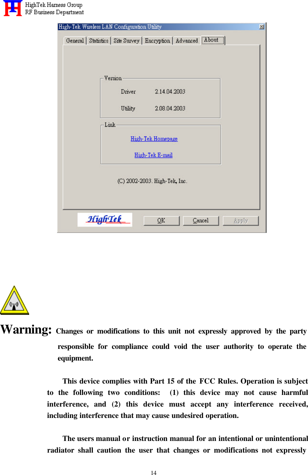
User Manual
Discussion / Help
Navigation