HILLSTONE NETWORKS E1100W Firewall Appliance User Manual Manual
Hillstone Networks Corp. Firewall Appliance Manual
Contents
- 1. Manual
- 2. Addendum
Manual

Hillstone StoneOS User Manual
Hillstone Hardware Reference Guide
www.hillstonenet.com
Hillstone Hardware Reference Guide
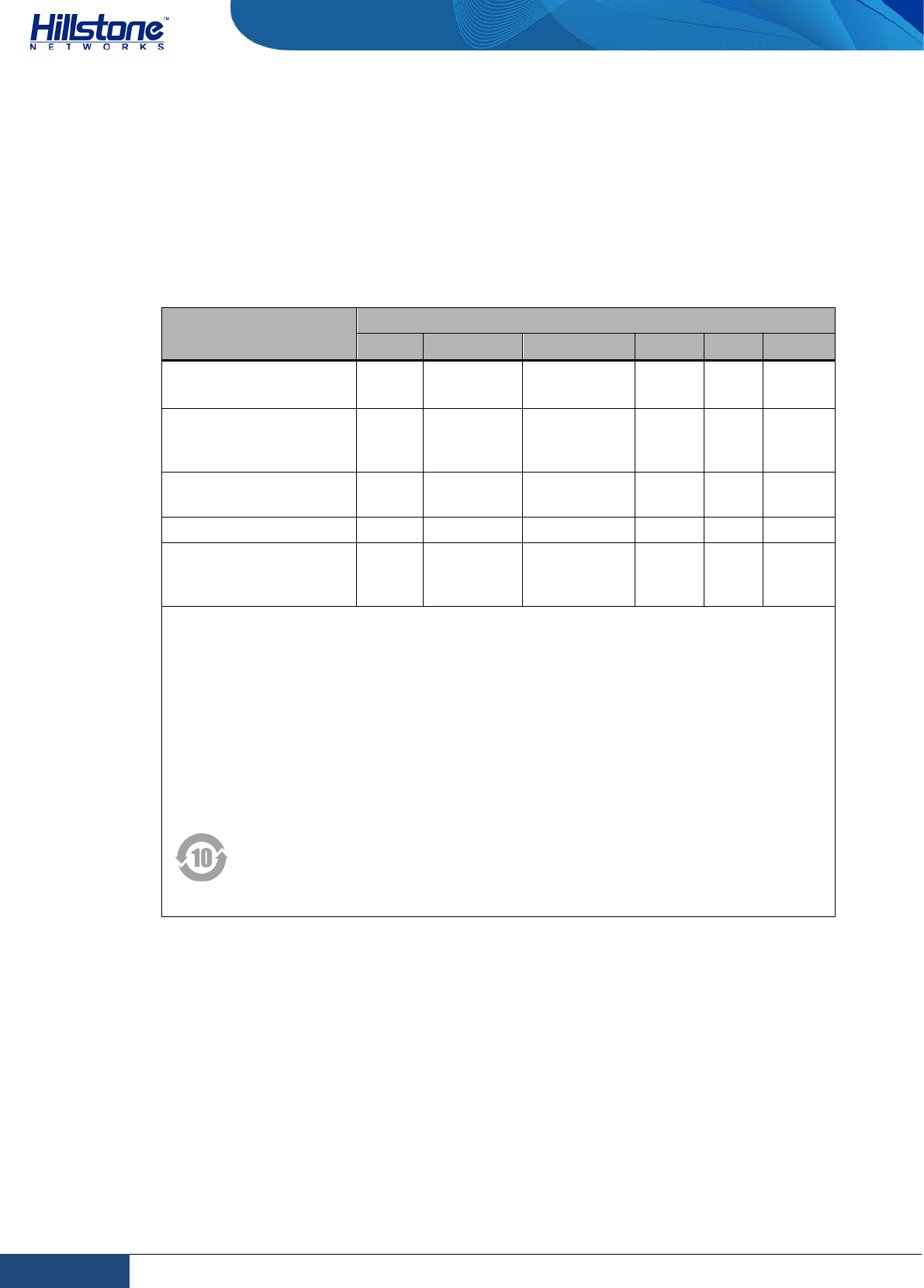
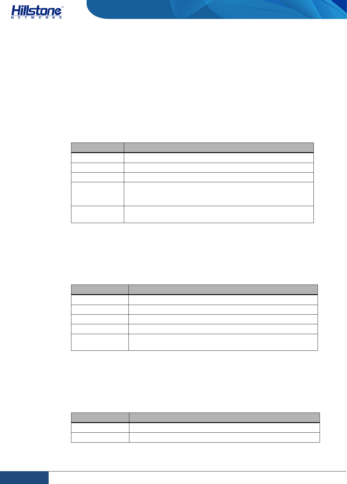
Name and Concentration of Toxic or Hazardous
Substances and Elements in Products
Component Toxic or hazardous substances and elements
Lead Mercury Cadmium Cr6+ PBB PDBE
Metal parts
(including fasteners) Χ O O O O O
Printed circuit board
assemblies and
components
Χ O O O O O
Cables and cable
assemblies Χ O O O O O
Plastics and Polymers Χ O O O Χ Χ
Electric components
other than circuit
boards
Χ O O O O O
O: Indicates that this toxic or hazardous substance in the material is below the
limit requirement defined in Requirements for Concentration Limits for Certain
Hazardous Substances in Electronic Information Products (SJ/T11363-2006) issued
by Ministry of Information Industry of PRC.
Χ: Indicates that this toxic or hazardous substance in the material exceeds the limit
requirement specified in Requirements for Concentration Limits for Certain
Hazardous Substances in Electronic Information Products (SJ/T11363-2006) issued
by Ministry of Information Industry of PRC.
Note: Not all components in the table are included in one product.
This symbol indicates the environment friendly use period of all products
and components. The period applies only to the normal operation
conditions specified in this guide.
2 Name and Concentration of Toxic or Hazardous Substances and Elements in Products | Hillstone

Hillstone Hardware Reference Guide
Preface
About This Guide
Thanks for choosing the network security products from Hillstone Networks, Inc.
This document is an installation guide for Hillstone devices to help you install the
Hillstone device properly.
This guide includes the following chapters:
♦ Chapter 1. Introduction
♦ Chapter 2. Installation Preparations
♦ Chapter 3. Installation
♦ Chapter 4. Boot and Configuration
♦ Chapter 5. Hardware Maintenance and Replacement
♦ Chapter 6. Troubleshooting
Document Conventions
This guide uses the following conventions for your convenience to read and
understand:
♦ Warning: Indicates improper operation that may cause serious damage to
equipment or injury to operators. Thus, operators must strictly follow the
operation rules.
♦ Caution: Indicates incorrect operation that may affect the normal use of the
equipment. Operators should be careful.
♦ Note: Indicates information that may help readers understand the content.
3 Preface | Hillstone

Hillstone Hardware Reference Guide
Table of Contents
CHAPTER 1 INTRODUCTION ........................................................................................................................................ 1
OVERVIEW ........................................................................................................................... ERROR! BOOKMARK NOT DEFINED.
HARDWARE OVERVIEW ......................................................................................................................................................... 1
Front Panel .................................................................................................................................................................. 1
Back Panel ................................................................................................................................................................... 1
LED Indicators ............................................................................................................................................................. 2
System Parameters ..................................................................................................................................................... 4
Ports ............................................................................................................................................................................ 5
CLR Button .................................................................................................................................................................. 6
Power Supply .............................................................................................................................................................. 6
CHAPTER 2 INSTALLATION PREPARATIONS ................................................................................................................. 8
INTRODUCTION ................................................................................................................................................................... 8
CLEANNESS REQUIREMENTS ................................................................................................................................................... 8
ESD PREVENTION ................................................................................................................................................................ 8
EMI PREVENTION ................................................................................................................................................................ 8
GROUNDING REQUIREMENTS ................................................................................................................................................. 9
WORKBENCH REQUIREMENTS ................................................................................................................................................ 9
OTHER SAFETY RECOMMENDATIONS ....................................................................................................................................... 9
UNPACKING ........................................................................................................................................................................ 9
INSTALLATION DEVICES/TOOLS/CABLES ................................................................................................................................... 9
CHAPTER 3 INSTALLATION .........................................................................................................................................11
BEFORE INSTALLATION ........................................................................................................................................................ 11
INSTALLING THE DEVICE ON A WORKBENCH ............................................................................................................................ 11
INSTALLING THE DEVICE ON A RACK ....................................................................................................................................... 12
CONNECTING CABLES ......................................................................................................................................................... 13
Connecting the Ground Wire .................................................................................................................................... 14
Connecting the Console Cable ................................................................................................................................... 14
Connecting the Ethernet Cable ................................................................................................................................. 14
Connecting an AC Power Cable ..................................................................................... Error! Bookmark not defined.
Connecting a DC Power Cable ....................................................................................... Error! Bookmark not defined.
Connecting a Power Adapter .................................................................................................................................... 16
VERIFYING INSTALLATION .................................................................................................................................................... 16
CHAPTER 4 BOOT AND CONFIGURATION .................................................................................................................... 1
INTRODUCTION ................................................................................................................................................................... 1
ESTABLISHING A CONFIGURATION ENVIRONMENT ...................................................................................................................... 1
Console (CON) Connection .......................................................................................................................................... 1
WebUI ......................................................................................................................................................................... 2
Tenet and SSH ............................................................................................................................................................. 3
BASIC CONFIGURATION ......................................................................................................................................................... 3
4 Table of Contents | Hillstone

Hillstone Hardware Reference Guide
CHAPTER 5 TROUBLESHOOTING ................................................................................................................................. 4
INTRODUCTION ................................................................................................................................................................... 4
LOSING THE ADMINISTRATOR PASSWORD ................................................................................................................................. 4
TROUBLESHOOTING POWER SYSTEM ....................................................................................................................................... 4
TROUBLESHOOTING THE CONFIGURATION SYSTEM ..................................................................................................................... 4
COPYRIGHT INFORMATION ........................................................................................................................................ 5
FCC STATEMENT: ........................................................................................................................................................ 6
5 Table of Contents | Hillstone

Hillstone Hardware Reference Guide
List of Figures
Figure 1-1: Front Panel of SG-6000-E1100 (WLAN version) ........................................... 1
Figure 1-2: SG-6000-E1100 (WLAN version) Back Panel ............................................... 2
Figure 3-1: Installing the Rubber Pads ...................................................................... 11
Figure 3-2: Installing the Floating Nuts ..................................................................... 12
Figure 3-3: Installing the Rack-mounting Ears (1U Chassis as example) ....................... 13
Figure 3-4: Installing the Device in a Rack (1U Chassis as example) ............................ 13
Figure 3-5: Connecting the Ground Wire (1U Chassis as example) ............................... 14
Figure 3-6: Connecting the Ethernet Copper Cable ..................................................... 15
Figure 3-7: Connecting the Ethernet Fiber Cable ........................................................ 16
Figure 4-1: Console Port Configuration ....................................................................... 1
Figure 4-2: Setting Parameters for the Terminal Session .............................................. 2
6 List of Figures | Hillstone

Hillstone Hardware Reference Guide
List of Tables
Table 1-1: Front Panel Description of SG-6000-E1100 (WLAN version) ...................................................................... 1
Table 1-2: Back Panel Description of SG-6000-E1100 (WLAN version) ....................................................................... 2
Table 1-3: Front Panel LED Descriptions ..................................................................................................................... 2
Table 1-4: System Parameters .................................................................................................................................... 4
Table 1-5: Console Port Attributes .............................................................................................................................. 5
Table 1-6: Auxiliary Port Attributes ............................................................................................................................. 5
Table 1-7: USB Port Attributes .................................................................................................................................... 5
Table 1-8: Gigabit Copper Port Attributes .................................................................................................................. 6
Table 1-9: Power Supplies of All Product Models ........................................................................................................ 7
Table 2-1: Dust Concentration Requirements in the Equipment Room ...................................................................... 8
7 List of Tables | Hillstone
Hillstone Hardware Reference Guide
Chapter 1 Introduction
Hardware Overview
A device can be installed in a cabinet/rack or placed on a workbench.
Front Panel
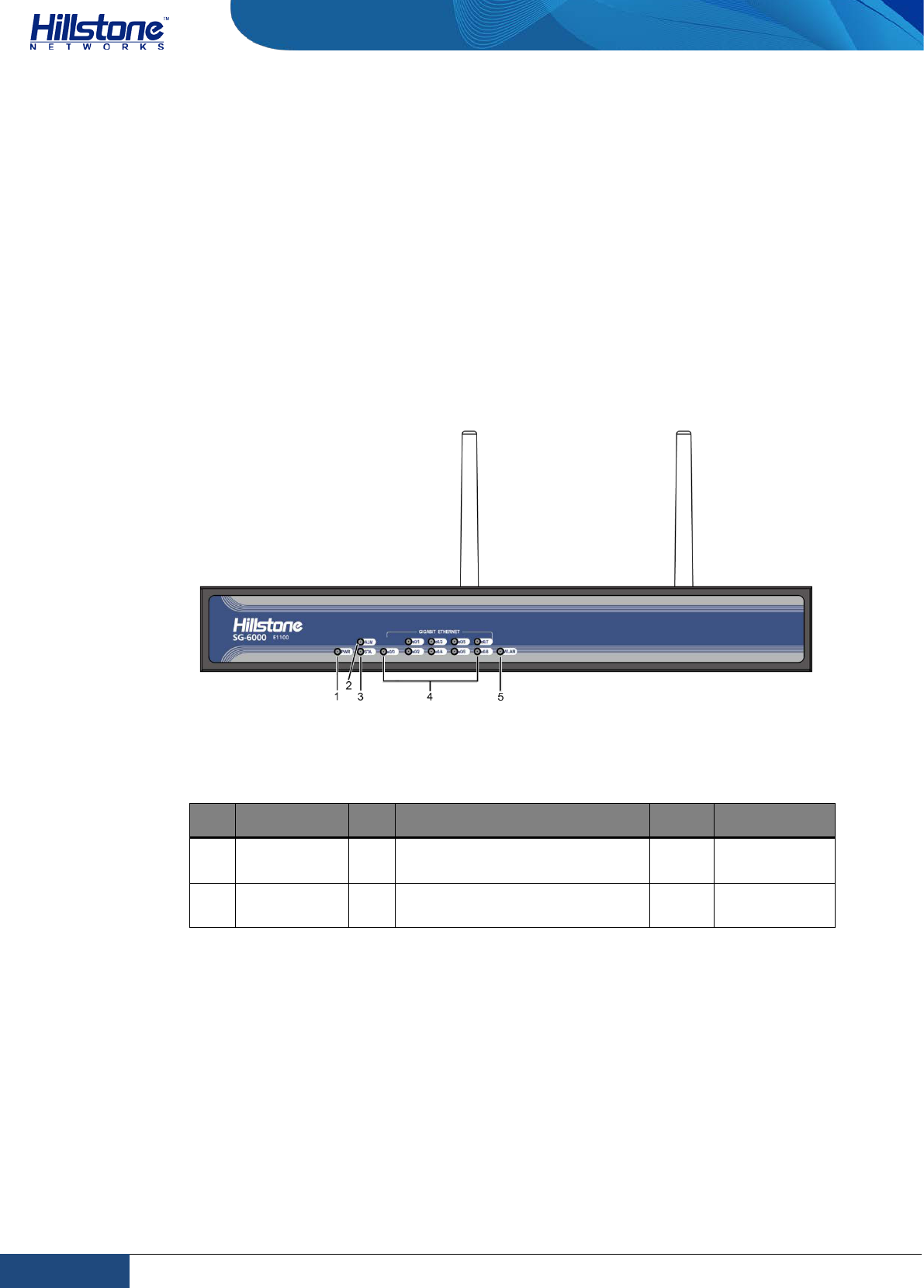
Figure 1-1: Front Panel of SG-6000-E1100 (WLAN version)
Table 1-1: Front Panel Description of SG-6000-E1100 (WLAN version)
No. Label No. Label No. Label
1 PWR: Power
LED 3 STA: Status LED 5 WLAN:
WLAN LED
2 ALM: Alarm
LED 4 e0/0 - e0/8: Gigabit Ethernet
port status LED - -
Back Panel
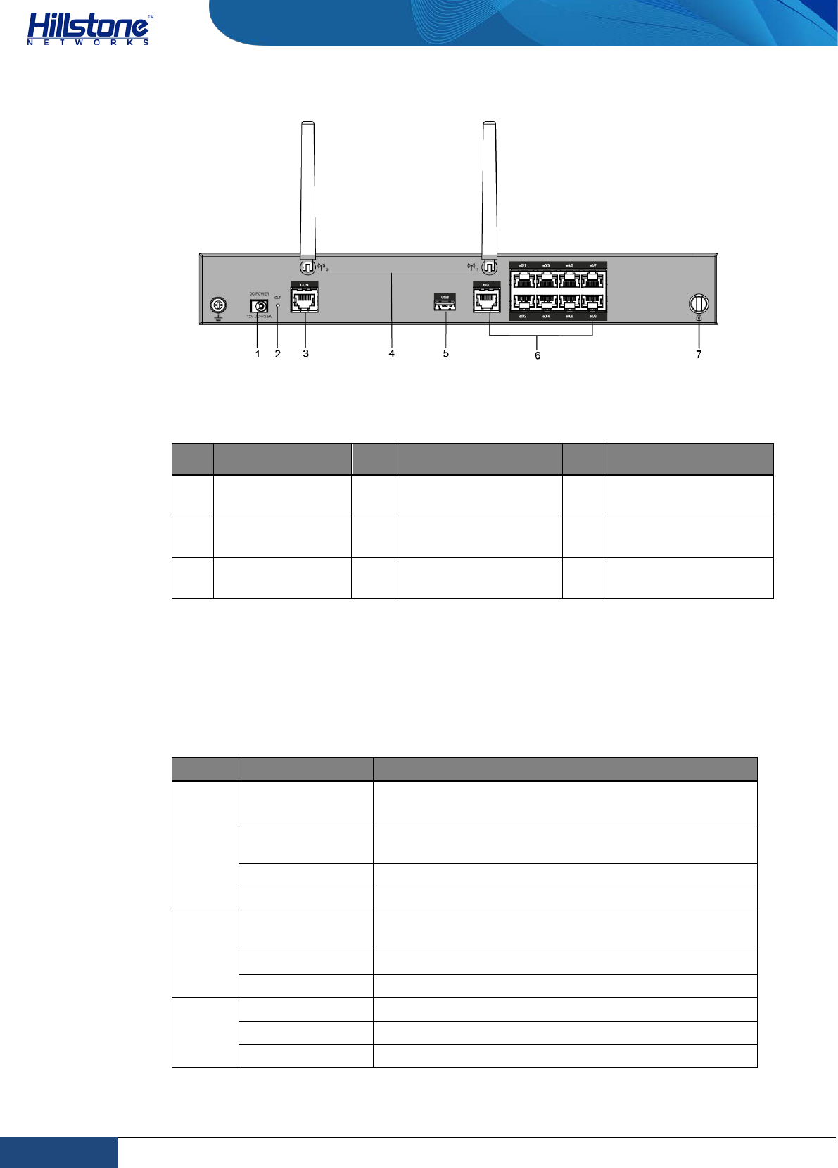
SG-6000-E1100 (WLAN version) uses the power adapter. The back panel of SG-
6000-E1100 (WLAN version) has 1 power supply socket, 1 Console port, 1 CLR
button, 9 Gigabyte Ethernet ports, 1 USB port, 1 grounding screw, 1 security
keyhole, and 2 SMA connectors for WLAN antennas. Figure 1-26 illustrates the back
panel of this model.
1 Chapter 1 Introduction | Hillstone
Hillstone Hardware Reference Guide
Figure 1-2: SG-6000-E1100 (WLAN version) Back Panel
Table 1-2: Back Panel Description of SG-6000-E1100 (WLAN version)
No. Label No. Label No. Label
1 DC POWER: DC
power interface 4 SMA connectors for
WLAN antennas 7 Security keyhole
2 CLR: CLR
button 5 USB: USB port - -
3 CON: Console
port 6 e0/0 - e0/8: Gigabit
Ethernet port - -
LED Indicators
The following table describes the meanings of LED indicators on the front panels of
Hillstone devices.
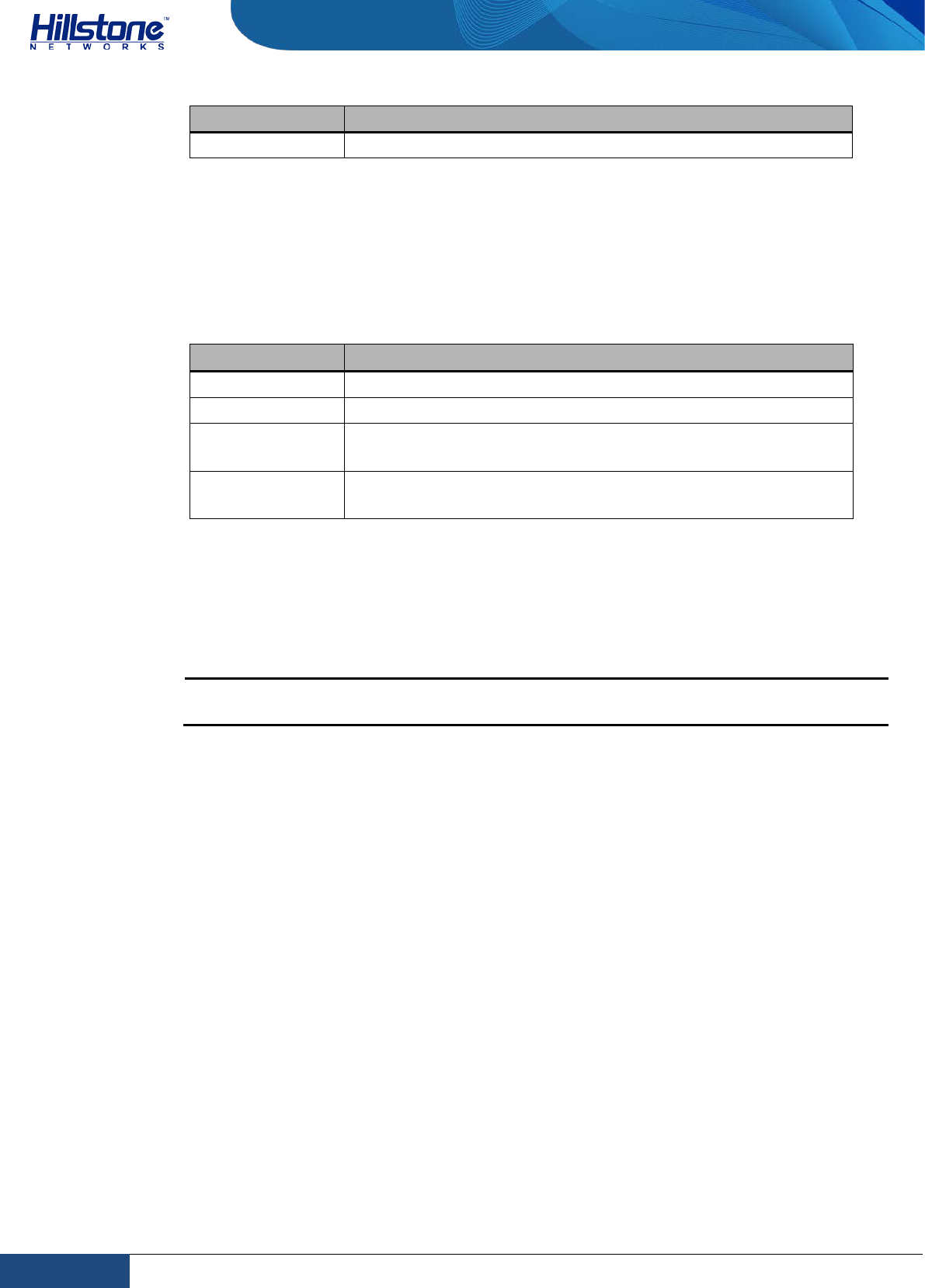
Table 1-3: Front Panel LED Descriptions
LED Color/Status Description
PWR
Green/Always
on The device power is running normally.
Orange/Always
on The device power is running abnormally.
Red/Always on Power failure so the system is down.
Off The device is powered off.
STA
Green/Always
on The system is booting.
Green/Blinking The system is running normally.
Red/Always on The system has failed to boot or has an error.
ALM
Red/Always on The system is sending alarm(s).
Green/Blinking The system is waiting.
Orange/Blinking The system is using a trial license.
2 Chapter 1 Introduction | Hillstone

Hillstone Hardware Reference Guide
Orange/Always
on The trial license has expired and there is no
legitimate license installed in the system.
Off The system is running normally.
PS0
Green/Always
on Power Supply PS0 is running normally.
Orange/Always
on Power Supply PS0 is running normally, but its fan
has failed. Change the power supply immediately.
Off Power Supply PS0 is powered off or has failed.
PS1
Green/Always
on Power Supply PS1 is running normally.
Orange/Always
on Power Supply PS1 is running normally, but its fan
has failed. Change the power supply immediately.
Off Power Supply PS0 is powered off or has failed.
HA
Green/Always
on Not using HA, this device is the master device.
Green/Blinking Two devices are in an HA cluster. This device is
working as the master.
Orange/Blinking Two devices are in an HA cluster. This device is
working as the slave.
Red/Blinking HA function has failed.
Off High Availability is disabled.
FAN
Green/Always
on The cooling system is running normally.
Orange/Always
on
One of the fans has failed, but the cooling system
can still fully function. Change the fan tray as soon
as possible.
Red/Always on The cooling system has a serious error or the fan
tray is
not fully inserted. The system will
automatically shut down in 15 seconds.
VPN
Green/Always
on The VPN tunnel is connected.
Orange/Always
on VPN is turned on but no tunnel is connected.
Off VPN is not in use.
SD
Green/Always
on SD card has been inserted and is in normal status.
Green/Blinking SD card is transmitting data.
Off No SD card is inserted.
LNK
Green/Always
on The link between this port and its peer device is in
normal status.
Off The link between this port and its peer device has
failed.
ACT Orange/Blinking The port is sending or receiving data.
Off No data is transmitted on this port.
e0/0-
e0/8
Green/Always
on The link between this port and its peer device is in
normal status.
Green/Blinking The port is sending or receiving data.
3 Chapter 1 Introduction | Hillstone
Hillstone Hardware Reference Guide
Off There is no connection between this port with the its
peer device, or t
he link between this port and its
peer device fails.
WLAN Green/Always
on The device discovers the built-in WLAN module.
Green/Blinking The WLAN module is sending or receiving data.
Notes:
♦ The STA and ALM LEDs will both turn red when there is a boot failure
caused by OS software damage. Contact your sales representative if this
occurs.
♦ As the number and type of LED indicators may vary from different
product models, please refer to the actual product.
System Parameters
The following table lists the system parameters of Hillstone devices of all models.
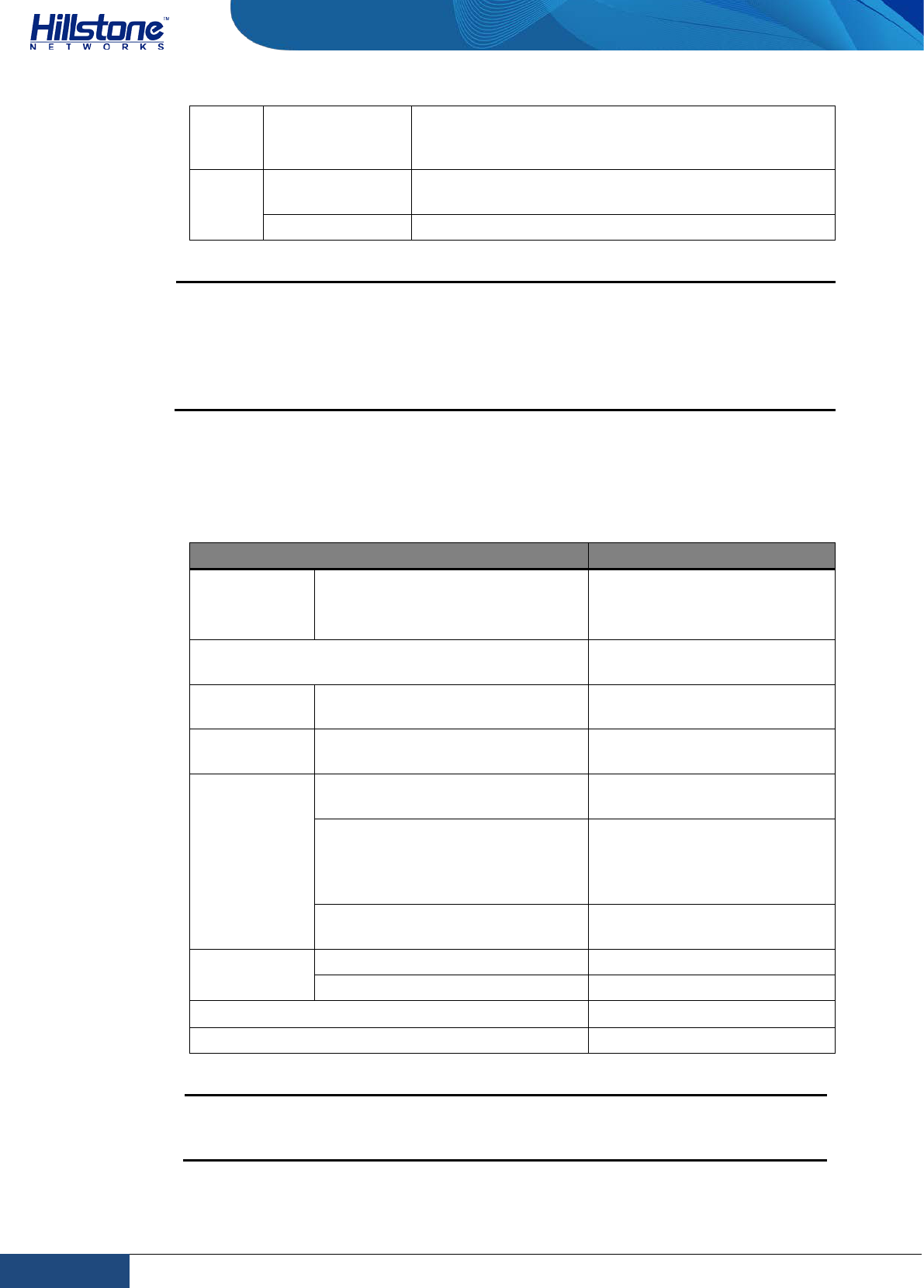
Table 1-4: System Parameters
Item Description
Interface SG-6000-E1100 (WLAN version)
9 Gigabit Ethernet ports
1 USB 2.0 Host port
1 Console port
CPU Dedicated 64-bit multi-core
processor
DDR SDRAM
SG-6000-E1100 (WLAN version)
1 GB
Flash Memory
SG-6000-E1100 (WLAN version)
512 MB
Size
SG-6000-E1100 (WLAN version)
320.0mm x 150.0mm x
44.0mm
SG-6000-E1100 (WLAN version)
Net weight: 1.5 kg
Gross weight: 2.0 kg
(accessories and packages
included)
SG-6000-E1100 (WLAN version)
30 W
Input Voltage AC 100-240V AC, 50/60Hz
DC -40 - -60V DC
Ambient Temperature 0℃-40℃
Relative Humidity 10%-95% (non-condensing)
Note: DDR SDRAM is the random access memory to store the communication
data for the CPU. Flash Memory is used for storing the operating system
firmware, configuration and application files.
4 Chapter 1 Introduction | Hillstone
Hillstone Hardware Reference Guide
Ports
This section introduces attributes of interfaces (ports) on the Hillstone devices,
including console port, auxiliary port, USB port, gigabit copper port, SFP port and
XFP port.
Console Port
Hillstone device provides an RS-232C asynchronous serial console port for you to
configure the device. Attributes for the console (CON) port are shown in the
following table.
Table 1-5: Console Port Attributes
Attribute Description
Connector RJ-45
Port Standard RS-232C
Baud Rate 9600/19200/38400/57600/115200 bit/s
Services Connect the CON port to the serial port of a PC and run a
terminal emulation program on the PC to configure the
device.
Transmission
Medium console cable
Auxiliary Port
Hillstone device provides an RS-232C asynchronous serial auxiliary (AUX) port.
Attributes for the auxiliary port are shown in the following table.
Table 1-6: Auxiliary Port Attributes
Attribute Description
Connector RJ-45
Port Standard RS-232C
Baud Rate 9600/19200/38400/57600/115200 bit/s
Services Aux port is used for debugging.
Transmission
Medium console cable
USB Port
Hillstone device provides up to two USB host ports. Attributes for the USB port are
shown in the following table.
Table 1-7: USB Port Attributes
Attribute Description
Connector USB Type-A interface
Port Standard USB 2.0 host interface
5 Chapter 1 Introduction | Hillstone
Hillstone Hardware Reference Guide
Attribute Description
Negotiation Mode 1.1/2.0 autosensing
Gigabit Copper Port
Hillstone device provides several fixed gigabit copper ports; the gigabit Combo port
also supports the copper cable connection. Attributes for the gigabit copper port are
shown in the following table.
Table 1-8: Gigabit Copper Port Attributes
Attribute Description
Connector RJ-45
Port Standard Auto-MDIX
Frame Format Ethernet_II
Ethernet_SNAP
Negotiation Mode 10/100/1000Mbps autosensing
Full/half-duplex
CLR Button
The CLR button is the pinhole of the front panel and is used to reset the device
back to the factory default settings. You can restore access to the device with this
button if the login password is lost.
Warning: Use this button with caution. Resetting the device will clear all existing
configurations.
To restore the factory default settings, take the following steps:
1. Turn off the power of the device.
2. Press the CLR button in the pinhole and switch on the power supply
simultaneously.
3. Keep pressing till the STA and ALM LEDs turn to constantly red, then stop
pressing. The device begins to restore to the original factory settings.
4. The system reboots after the default settings restored.
Power Supply
Single/Dual power supply: Some product modules adopt single power supply,
while others adopt dual power supplies, i.e. there are two power inputs installed in
one device. Dual power supplies ensure uninterrupted power by instantly enabling
the standby power supply when the active power supply fails to work.
AC/DC power supply: For some product modules (as listed below), you can
choose either AC or DC power supply.
6 Chapter 1 Introduction | Hillstone
Hillstone Hardware Reference Guide
Hot-swappable: According to whether the power supply is hot-swappable or not,
the power supply is classifies into three types:
♦ Hot-swappable power supplies are removable modules which can be
replaced at any time;
♦ Fixed power supplies are irreplaceable and cannot be removed.
♦ External power adapter connects to the external AC power supply.
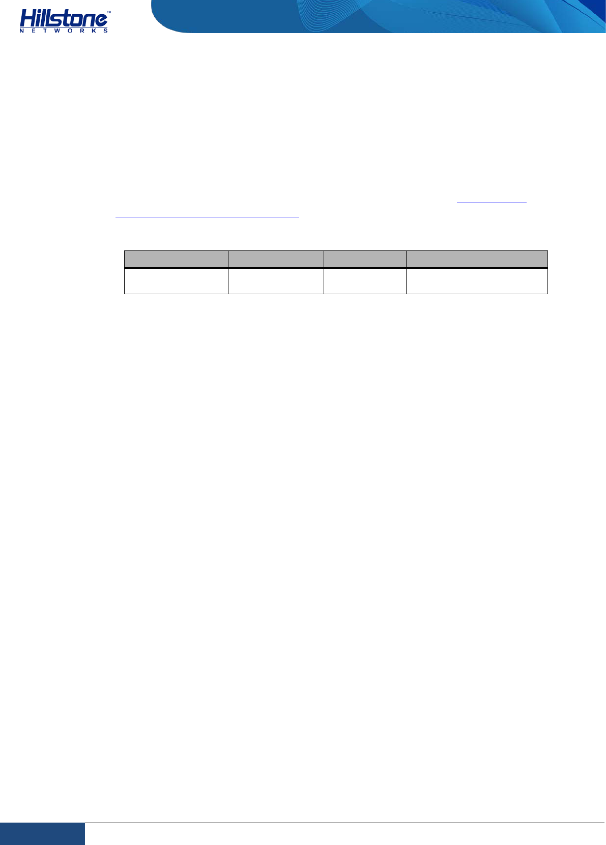
For instructions on how to replace power supply modules, refer to Installing and
Removing the Power Supply Module.
Table 1-9: Power Supplies of All Product Models
Model Description AC/DC Power Supply Type
SG-6000-E1100
(WLAN version)
Single AC External
7 Chapter 1 Introduction | Hillstone
Hillstone Hardware Reference Guide
Chapter 2 Installation Preparations
Introduction
To prevent personnel injury and equipment damage, please carefully read all the
safety warnings and cautions in this chapter before the installation.
Hillstone products are designed for indoor use. To ensure the normal operation and
to prolong the service lifetime, the installation site must meet the following
requirements:
Cleanness Requirements
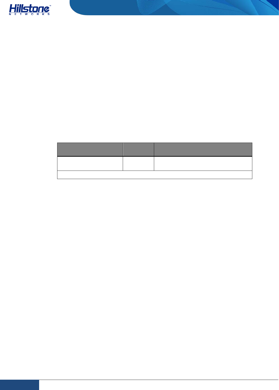
Table 2-1: Dust Concentration Requirements in the Equipment Room
Mechanical Active
Material Unit Content
Dust particle particle/m3 ≤3×10⁴ (No visible dust on the table
in 3 days)
Note:Diameter of dust particle≥5μm
ESD Prevention
To prevent electrostatic discharge (ESD) damage, ensure that:
♦ The device is well grounded. The grounding screw is properly grounded.
♦ Take dustproof measures for the equipment room.
♦ Maintain proper humidity and temperature levels.
♦ Do not disassemble the equipment without permission from the vendor, or
you may cause danger and void your warranty.
EMI Prevention
All possible electromagnetic interference (EMI) sources, external or internal, can
affect the device by capacitance coupling, inductance coupling, electromagnetic
radiation, and common impedance coupling (including the grounding system).
To prevent or reduce EMI:
♦ Take measures to protect the power system from power interference.
♦ It’s better to separate the floor where the device is installed from the
grounding device and lighting-proof device of the power source.
♦ Keep the device away from radio stations, radar, and other high-frequency
and high-current devices.
8 Chapter 2 Installation Preparations | Hillstone

Hillstone Hardware Reference Guide
♦ Use electromagnetic shielding when necessary.
Grounding Requirements
To use the device more safely:
♦ Ensure that the grounding screw of the chassis is well grounded via the
grounding wire.
♦ Ensure that the grounding pin of the power plug is well grounded.
Workbench Requirements
Before the installation, ensure your workbench is properly prepared as follows:
♦ Make sure that you provide adequate space near the intake and exhaust vents
of the device for heat dissipation.
♦ Make sure the rack is equipped with a good ventilation system.
♦ Make sure the rack is strong enough to support the weight of a fully equipped
device.
♦ Make sure the rack is well grounded.
Other Safety Recommendations
The directions below are also recommended for you to follow:
♦ Keep the device far away from moist areas and heat sources.
♦ Wear an ESD wrist strap correctly when handling the device.
♦ Be careful with laser emission. Do not directly stare into apertures of fiber-
optic connectors that emit laser radiation.
♦ Use uninterrupted power supply (UPS).
Unpacking
Verify the parts received according to your purchasing contract and packing list to
ensure that you have received all the items necessary. If you have any problem,
please contact your sales representative.
Installation Devices/Tools/Cables
A Hillstone device is shipped with a power cable and a console cable, and you
should have the following items before the installation:
♦ Terminal: Configuration terminal (e.g. an ordinary PC).
♦ Tools: Philips screwdrivers and ESD wrist strap.
9 Chapter 2 Installation Preparations | Hillstone

Hillstone Hardware Reference Guide
♦ Cables: Power cable, console cable and Ethernet cable.
10 Chapter 2 Installation Preparations | Hillstone
Hillstone Hardware Reference Guide
Chapter 3 Installation
Before Installation
A yellow seal with dark ink characters is stuck on a mounting screw of the chassis.
Keep the seal intact. The sales representative will check this seal before
maintenance operation. Please get the permission of your sales representative
before opening the chassis yourself. Warranty will be void if you disassemble the
chassis without authorization.
Before installation, make sure that:
♦ You have read Chapter 2 Installation Preparations carefully.
♦ The requirements in Chapter 2 Installation Preparations are satisfied.
Hillstone products can be installed:
♦ On a workbench
♦ On a standard 19-inch rack
Installing the Device on a Workbench
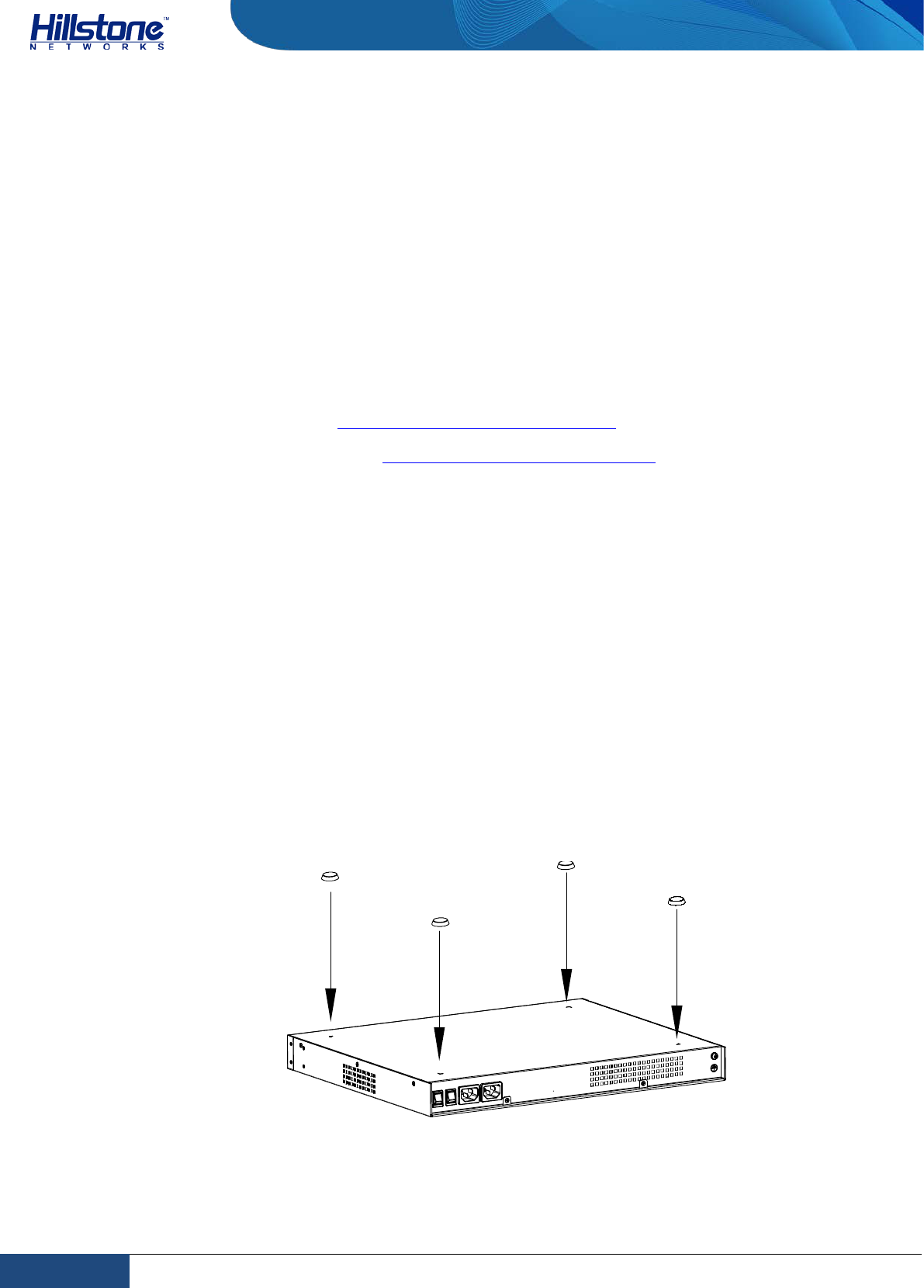
Hillstone product can be placed on a stable and clean workbench. For skid
prevention, take the following steps to fit anti-skid pads on the device before
installing:
Step 1: Tear off the sticker from the rubber pad.
Step 2: Press the sticky side of the pad to the right-angle die-pressed mark on the
bottom panel of the chassis. See Figure 3-1.
Figure 3-1: Installing the Rubber Pads
Check the following specifications when installing the device on a workbench:
11 Chapter 3 Installation | Hillstone
Hillstone Hardware Reference Guide
♦ Make sure the workbench is stable and well grounded.
♦ Make sure the intake and the exhaust vents are unblocked, and keep the
device well ventilated.
♦ Do not place any heavy object on the top of the chassis.
Installing the Device on a Rack
Before mounting the device on a rack, ensure that the power is off, and the rack is
stable enough and well grounded. Hillstone devices are designed for a 19-inch
standard rack.
To mount the chassis on a rack:
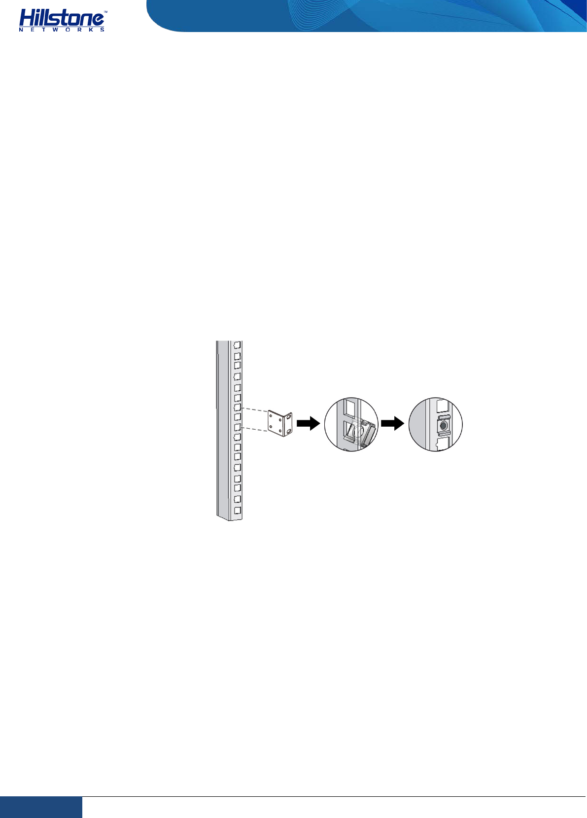
Step 1:Use rack-mounting ear to mark the positions of floating nuts on the front
rack posts, as shown in Figure 3-2.
Figure 3-2: Installing the Floating Nuts
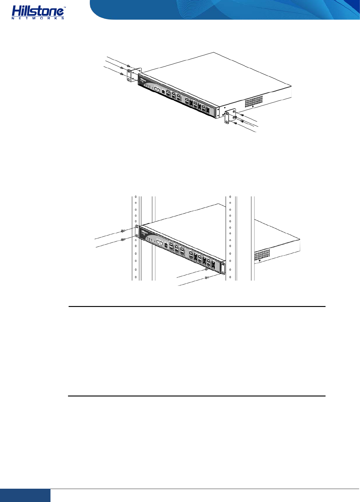
Step 2: Attach rack-mounting ears to the left and right side panels of the chassis
respectively, and then fasten the rack-mounting ears with suitable screws, as
shown in Figure 3-3.
12 Chapter 3 Installation | Hillstone
Hillstone Hardware Reference Guide
Figure 3-3: Installing the Rack-mounting Ears (1U Chassis as example)
Step 3: Take out screws from the accessory box and fasten the rack-mounting ears
of the chassis in the rack with the screws. Keep the center of the rack-mounting ear
and the center of the rack hole horizontally even, as shown in Figure 3-4.
Figure 3-4: Installing the Device in a Rack (1U Chassis as example)
Cautions:
♦ The rack-mounting ears cannot bear weight. Make sure the chassis is
supported by the platform under it when mounted into a rack.
♦ For better ventilation, there should be a clearance space between two
equipments.
♦ If the rack accommodates only one device, put the device on the
bottom.
♦ The floating nuts in the accessory box can only fit in the 9mm x 9 mm
squared holes of standard racks and they can be used when no original
rack nuts are available.
Connecting Cables
This section describes how to connect cables to the device, including connecting the
ground wire, the console cable, the Ethernet cable and the power cable.
13 Chapter 3 Installation | Hillstone
Hillstone Hardware Reference Guide
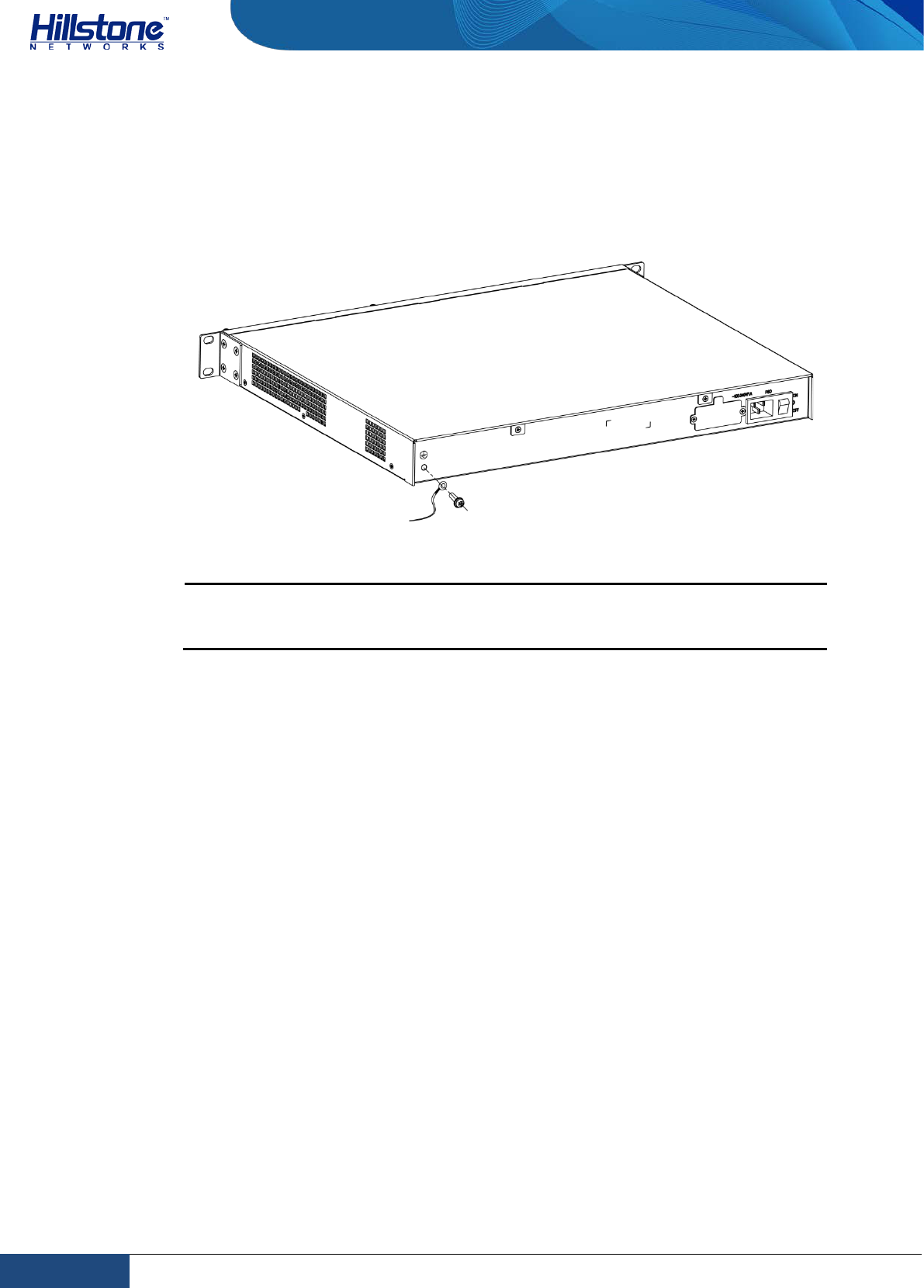
Connecting the Ground Wire
To meet safety requirements, you must correctly connect the grounding screw on
the chassis to the earth ground by a grounding wire. The grounding resistance
should be less than 5Ω.
Figure 3-5: Connecting the Ground Wire (1U Chassis as example)
Warning: The correct connection of the ground wire on the chassis is an
essential safeguard against lightning shocks and interference. You must
properly connect the ground wire when installing and using the device.
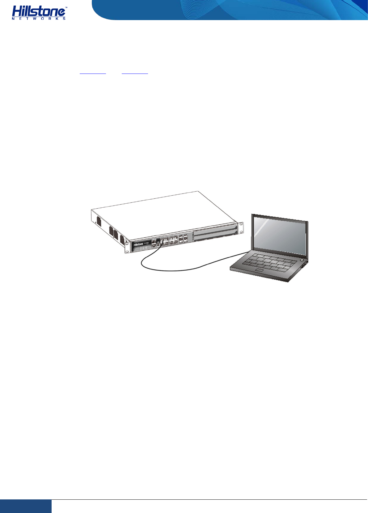
Connecting the Console Cable
Hillstone device provides an RS-232C asynchronous serial console (CON) port,
through which you can configure the device. The console cable is an 8-core shielded
cable, which has an RJ-45 connector that can be connected to the Console port of
the device and a DB-9 (female) connector that can be connected to the serial port
of a console terminal.
Perform the following steps to connect the device and the console terminal:
1. Select a console terminal. You may choose an ordinary PC or a standard
ASCII terminal with an RS-232C serial port.
2. Connect the console cable. Connect the RJ-45 end of the cable to the Console
port of the device, and then connect the DB-9 connector of the cable to the
console terminal.
Connecting the Ethernet Cable
Hillstone products provide 1000Mbps electrical Ethernet ports, SFP ports, XFP ports
and Ethernet Combo ports (Electrical port + Optical port). The electrical Ethernet
port can be connected by a straight-through cable (also called standard cable) or a
crossover cable. The SFP port should use a SFP optical module, which can be
connected with crossover cable or straight-through cable, or use a SFP electric
14 Chapter 3 Installation | Hillstone
Hillstone Hardware Reference Guide
module connected by a single-mode or multi-mode cable. The XFP port uses single-
mode or multi-mode cables to access Ethernet.
All SFP Port and XFP Port optical modules of Hillstone products use LC-type optical
connector; therefore, you should connect the optical modules using optical fiber
ended with LC-type connector.
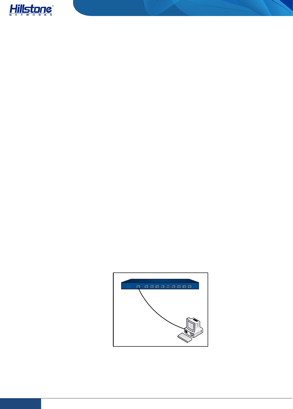
Connecting the Ethernet Copper Cable
Follow the guidelines below when connecting cables to the ports:
♦ Be careful not to connect the Ethernet port to the wrong ports. Read the label
above the port carefully.
♦ For electrical Ethernet connection, use crossover cable or straight-through
cable.
Figure 3-6: Connecting the Ethernet Copper Cable
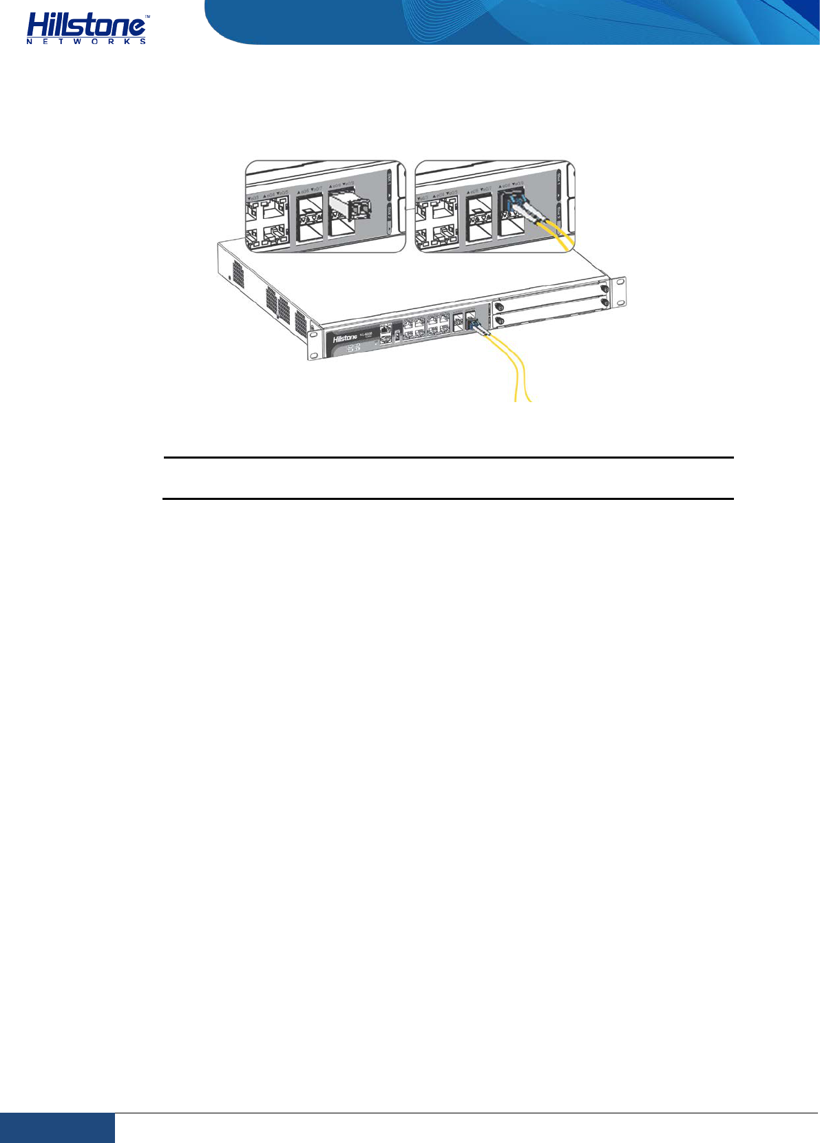
Connecting the Ethernet Fiber Cable
Follow the guidelines below when connecting cables to the ports:
♦ Be careful not to connect the Ethernet port to the wrong ports. Read the label
above the port carefully.
♦ For SFP port connection, the optical module should be inserted into SFP port
before installing the LC-type connector to the optical module; the copper SFP
module should be connected by crossover cable or straight-through cable.
♦ For XFP ports, insert the XFP optical module into the XFP port before
connecting the LC-type connector to the module.
Keep the followings in mind when connecting fiber cables:
♦ The curvature radius should be greater than 10cm. Avoid excessive bending
of the cable.
♦ Ensure the Tx and Rx ends are connected correctly.
♦ Keep the connector of the optical cable clean.
15 Chapter 3 Installation | Hillstone
Hillstone Hardware Reference Guide
Figure 3-7: Connecting the Ethernet Fiber Cable
Warning: Laser danger! To protect your eyes from radiation harm, do not
stare into a cable connector connected to a laser generator.
Connecting a Power Adapter
To provide the power supply, connect the power adapter of the devices with the
external AC power supply as follows:
1. Insert the DC output plug of the power adapter into the AC power interface at
the back panel of the device.
2. Connect the power adapter to the external AC power supply.
Verifying Installation
After you complete the installation with all the above steps, you still need to verify
the following items.
♦ All the cables are properly connected.
♦ The grounding wire of the device is correctly connected.
♦ The air vents on both side panel of the device are unblocked, and there is
enough space around for heat dissipation.
♦ The expansion modules, power supply modules and fan tray are correctly
installed (for some products).
♦ The power source meets the requirements of the device.
♦ If the device is rack-mounted, make sure the rack is stable enough. If the
device is placed on a workbench, make sure the workbench is stable and
clean.
16 Chapter 3 Installation | Hillstone

Hillstone Hardware Reference Guide
17 Chapter 3 Installation | Hillstone
Hillstone Hardware Reference Guide
Chapter 4 Boot and Configuration
Introduction
This chapter describes the initial system boot and basic configuration of Hillstone
SG-6000 series, using a PC as the console terminal.
Establishing a Configuration Environment
Hillstone devices support both local and remote configuration. Administrators can
use the following configuration methods.
♦ Console (CON) connection
♦ WebUI
♦ Telnet or SSH
Console (CON) Connection
For initial system configuration, you have to establish a Console connection
environment (connect the device to a configuration terminal through its Console
port).
To connect the PC to the CON port of the device, take following steps:
1. Set up a local configuration environment. Connect the Console port to the
serial port of a PC through a console cable, as shown in Figure 4-1:
Figure 4-1: Console Port Configuration
2. Run the terminal emulation program on the PC (e.g. hyper terminal of
Windows XP/Windows 2000) to set up a connection. Set the parameters of the
CON port
Console cable
RS-232 serial port
PC
1 Chapter 4 Boot and Configuration | Hillstone
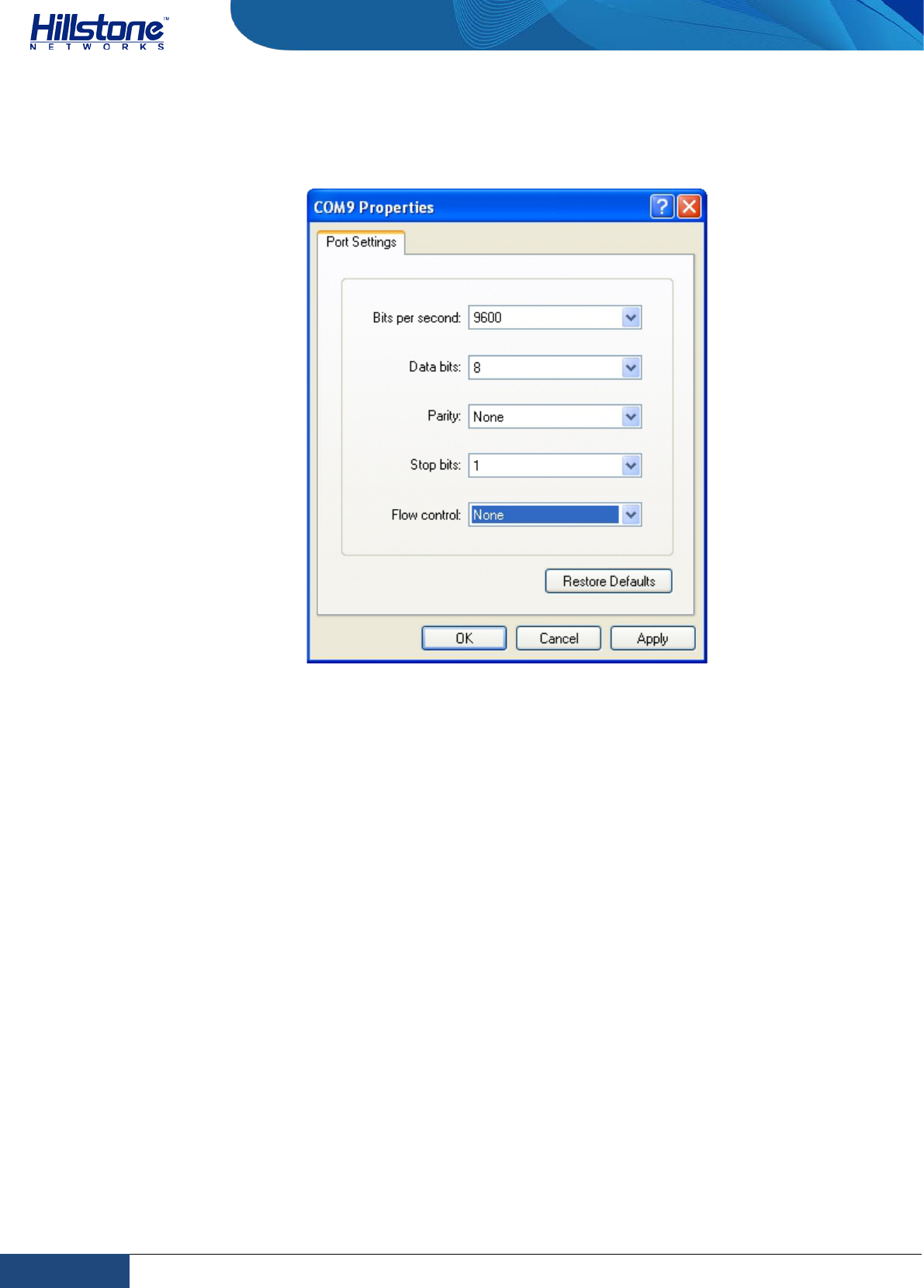
Hillstone Hardware Reference Guide
terminal session to 9600bps, 8 data bits, 1 stop bit, none parity, and none
flow control, as shown in Figure 4-2:
Figure 4-2: Setting Parameters for the Terminal Session
3. Switch on the power supply, and the device performs self-test and initializes
the configuration automatically. If the booting succeeds, the system will
display the command line prompt “login”. Enter the default administrator
name and password “hillstone” at the “login” and “password” prompts, press
“Enter”. And now you are successfully logged in and accessing the CLI.
4. Enter commands to configure or view running status. Enter a question mark
“?” to get help on commands whenever you want.
WebUI
The ethernet0/0 (e0/0) port has a default IP address of 192.168.1.1/24, and all the
management functions of this port are enabled by default. Administrators can
access the WebUI through e0/0.
To log in the device’s WebUI, take the following steps:
1. Set up the IP address of the management PC on the same subnet as
192.168.1.1/24. Connect the management PC to the e0/0 port through an
Ethernet cable.
2. Launch a Web browser of the management PC, enter the URL
http://192.168.1.1 in the address bar, and then press Enter.
2 Chapter 4 Boot and Configuration | Hillstone

Hillstone Hardware Reference Guide
3. Enter the default administrator name and password “hillstone” in both the
Login and Password text boxes.
4. Click the Login button to enter WebUI main page. Then you can set other
configurations to the device.
Tenet and SSH
You can also establish Telnet and SSH configuration environments. For more
information, please see StoneOS User Manual.
Basic Configuration
Before you begin to use the device, you should be familiar with its features and
your network deployment. Different device position in the network requires
different topology design, working mode and policy configuration.
The basic configurations may include:
1. Create security zones, including the link layer (L2) and network layer (L3).
Bind different interfaces to correct security zones respectively.
2. Assign IP addresses to interfaces.
3. Configure the management functions of the interfaces and create the security
policy rules.
4. Assign proper network addresses and configure the NAT rules as needed.
5. Keep network connectivity by configuring routes.
6. Configure security policy rules between security zones.
7. Configure network parameters, such as DHCP and DNS agent, etc.
For more information, see StoneOS User Manual.
3 Chapter 4 Boot and Configuration | Hillstone

Hillstone Hardware Reference Guide
Chapter 5 Troubleshooting
Introduction
This chapter provides solutions to some common problems of Hillstone devices.
Losing the Administrator Password
If you lose the administrator password, please contact your local sales
representative.
Troubleshooting Power System
Check the PWR LED on the front panel of the device. If the power supply is
functioning normally, the PWR LED lights steadily in green color. If the LED is off,
perform the following steps:
♦ Make sure the power supply cable is connected correctly.
♦ Ensure that the voltage of the power source conforms to the required voltage.
For the PWR LED information, see LED Indicators.
Troubleshooting the Configuration System
The Console configuration terminal shows system booting message when the device
is powered on. If the configuration system has failed, it displays error information
or nothing at all.
If the configuration terminal shows no information, perform the following steps:
♦ Make sure the power supply is correctly connected and powered on.
♦ Verify the Console cable is connected properly.
♦ Ensure the terminal configuration settings are correct.
If above steps reveal no error, the Console cable may be broken.
4 Chapter 5 Troubleshooting | Hillstone

Hillstone Hardware Reference Guide
Copyright Information
Copyright © 2014, Hillstone Networks, lnc. All rights reserved.
Hillstone, Hillstone Networks logo, StoneOS, StoneManager, Hillstone PnPVPN, UTM Plus are
trademarks of Hillstone Networks.
All other trademarks or registered marks are the property of their respective owners. Hillstone
Networks assumes no responsibility for any inaccuracies in this document. Hillstone Networks
reserves the right to change, modify, transfer, or otherwise revise this publication without
notice.
Hillstone Networks Website www.hillstonenet.com posts the latest information.
5 Copyright Information | Hillstone

Hillstone Hardware Reference Guide
FCC Statement:
This device complies with Part 15 of the FCC Rules. Operation is subject to the following two
conditions: (1) this device may not cause harmful interference, and (2) this device must accept
any interference received, including interference that may cause undesired operation.
Caution: The user is cautioned that changes or modifications not expressly approved by the party
responsible for compliance could void the user's authority to operate the equipment.
Note: This equipment has been tested and found to comply with the limits for a Class B digital
device, pursuant to part 15 of the FCC Rules. These limits are designed to provide reasonable
protection against harmful interference in a residential installation. This equipment generates,
uses and can radiate radio frequency energy and, if not However, there is no guarantee that
interference will not occur in a particular installation. If this equipment does cause harmful
interference to radio or television reception, which can be determined by turning the equipment
off and on, the user is encouraged to try to correct the interference by one or more of the
following measures:
—Reorient or relocate the receiving antenna.
—Increase the separation between the equipment and receiver.
—Connect the equipment into an outlet on a circuit different from that to which the receiver is
connected.
—Consult the dealer or an experienced radio/TV technician for help.
FCC Radiation Exposure Statement
This equipment complies with FCC RF radiation exposure limits set forth for an uncontrolled
environment. This transmitter must not be co-located or operating in conjunction with any other
antenna or transmitter.
6 FCC Statement: | Hillstone

Hillstone Hardware Reference Guide
Industry Canada Statement:
This device complies with RSS-210 of the Industry Canada Rules. Operation is subject to the
following two conditions: 1) this device may not cause interference and 2) this device must
accept any interference, including interference that may cause undesired operation of the
device.
This class B digital apparatus complies with Canadian ICES-003
IC Radiation Exposure Statement: This equipment complies with IC radiation exposure limits set
forth for an uncontrolled environment.
Avis d’Industrie Canada:
Cet appareil est conforme à la norme CNR-210 des règlements d’Industrie Canada. Son
fonctionnement est sujet aux deux conditions suivantes: 1) Cet appareil ne doit pas provoquer
d’interférences et 2) Cet appareil doit accepter toutes les interférences, y compris celles
pouvant entraîner son dysfonctionnement. Cet appareil numérique de la classe B est conforme
à la norme NMB-003 du Canada Avis d’Industrie Canada sur l’exposition aux Rayonnements:
Cet appareil est conforme aux limites d’exposition aux rayonnements d’Industrie Canada pour
un environnement non contrôlé.
European notice
The equipment named above is confirmed to comply with the requirements setout in the Council
Directive on the Approximation of the Laws of the Member States relating to Electromagnetic
Compatibility (2004/108/EC), Low-voltage Directive (2006/95/EC) and R&TTE (1999/5/EC).
The equipment passed the test which was performed according to the following European
standards:
•ETSI EN 301 489-1 V1.9.2 (2011-09)
•ETSI EN 301 489-17 V2.2.1 (2012-09)
•ETSI EN 300 328 V1.8.1 (2012-06)
•EN 301 893 V1.7.1 (2012-06)
•EN 62311: 2008
•EN 60950-1:2006 + A11:2009 + A1:2010 + A12:2011
7 FCC Statement: | Hillstone

Hillstone Hardware Reference Guide
8 FCC Statement: | Hillstone