HITACHI VCR Manual L9911246
User Manual: HITACHI HITACHI VCR Manual HITACHI VCR Owner's Manual, HITACHI VCR installation guides
Open the PDF directly: View PDF ![]() .
.
Page Count: 42
HITACHI
InstructionManual
f
vllSI
Video Deck
VT-F350A
Hitachi Home Electronics (America), Inc.
For information concerning repairs, operation or
technical assistance, please contact the Service
Department of your nearest Regional Office.
Eastern Regional Office
1290 Wall Street West, Lyndhurst, New Jersey 07071
Tel. 201-935-8980
Mid-Western Regional Office
1400 Morse Ave., Elk Grove Village, II1.60007
Tel. 708-593-1550
Southern Regional Office
510 Plaza Drive College Park, Georgia 30349
Tel. 404-763-0360
Western Regional Office
401 West Artesia Boulevard, Compton, California
90220
Tel. 213-537-8383
HITACHI SALES CORPORATION OF
HAWAII, INC.
3219 KoapakaStreet, Honolulu,Hawaii 96819
Tel. 808-836-3621
HITACHI (HSC) CANADA INC.
3300 Trans Canada Highway, Pointe Claire,
Quebec, H9R 1B1, CANADA
Tel. 514-697-9150
IPlease read this instruction manual
carefully before use end refer to it if
any difficulties arise.
FEATURES
• VHS Hi-Fi stereo system
•Auto head cleaning system
•Setting 8 programs/1 year is possible with
built-in programmable timer
•Cable-compatible frequency synthesizer
quartz tuner
•Auto tracking
•Automatic rewind
•Remote control for use in common by
TV/VCR
• Intelascan feature
•Television Sound (MTS) isMultichannel
receivable
TABLE OF CONTENTS
FOR YOUR SAFETY ................................ 3
IMPORTANT SAFEGUARDS ................... 4
CONTROLS AND FEATURES ................... 6
INSTALLATION ..................................... 10
VIDEO CHANNEL SE'I-rlNG ................... 16
NORMAL TV VIEWING .......................... 16
CONNECTION WITH A/V "IV ................. 17
SETTING THE CLOCK ........................... 18
CHANNEL TUNING ............................... 20
VCR FUNCTION SETTING .... _................ 22
CASSETTE TAPES ................................ 24
RECORDING TV PROGRAMS ................ 24
INSTANT RECORDING .......................... 26
PLAYBACK .......................................... 27
TIMER RECORDING .............................. 29
RECALLING THE PROGRAM ................. 31
CLEARING INFORMATION FROM A
PROGRAM ........................................ 32
PROGRAM PRIORITY ........................... 32
HOW TO OPERATE YOUR TV BY USING
THE REMOTE CONTROL UNIT ............ 33
RECORDING FROM ANOTHER VCR ...... 38
RECORDING FROM A VIDEO
CAMERA .......................................... 38
USING AS AN AUDIO DECK ................. 37
HEAD CLEANING ................................. 38
PERIODIC MAINTENANCE .................... 38
PROBLEM GUIDE ................................. 39
SPECIFICATIONS .................................. 40
SPANISH QUICK USE GUIDE ................ 43
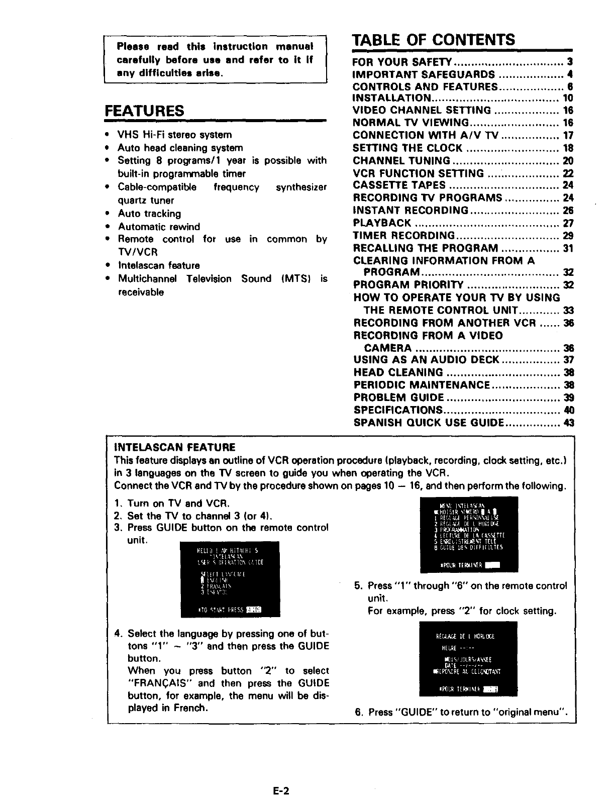
INTELASCAN FEATURE
This feature displays an outline of VCR operation procedure (playback, recording, clock setting, etc.)
in 3 languages on the TV screen to guide you when operating the VCR.
Connect the VCR and TV by the procedure shown on pages 10 - 16, and then perform the following.
1, Turn on TV and VCR.
2, Set the TV to channel 3 (or 4),
3. Press GUIDE button on the remote control
unit.
4. Select the language by pressing one of but-
tons "1" - "3" and then press the GUIDE
button.
When you press button "2" to select
"FRAN(_AIS" and then press the GUIDE
button, for example, the menu will be dis-
played in French.
5. Press "1" through "6" on the remote control
unit.
For example, press "2" for clock setting.
6. Press "GUIDE" to return to "original menu".
E-2
FOR YOUR SAFETY
Power supply: AC 120V. 60 Hz only
The POWER switch switches the VCR on and
off. leaving the clock/timer unaffected.
If the unit is to be left unattended for along
period, it is recommended that the unit be
completely switched off and the plug
removed.
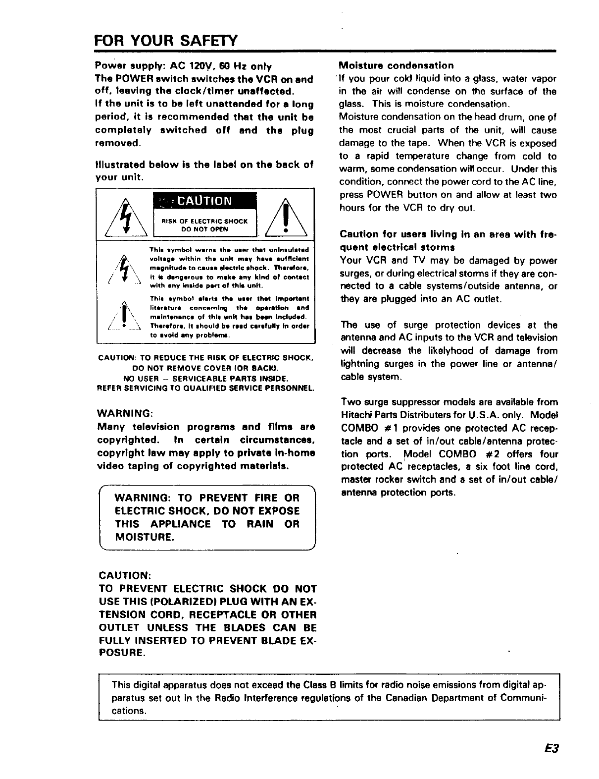
Illustrated below is the label on the back of
'our unit.
RISK OF ELECTRIC SHOCK
DO NOT OPEN
This lymbol worn= the ulle¢ that unlnau]atad
voltage within th@ unit rely have gufflclent
mmgnitude to cause electfI© ,hock. Therefore.
tt b= dlng@voug to mike any kind of ©ontltct
with any inside pert of this unit.
Thim tymbol alerts the user thmt Important
literature concerning the oper inlorl and
rnlintenance of this unit hi| been Included.
Therefore. It |hould be reed ¢Jrofull¥ tn Order
to ilvoid shy probiemm.
CAUTION: TO REDUCE THE RISK OF ELECTRIC SHOCK,
00 NOT REMOVE COVER (OR BACKI.
NO USER - SERVICEABLE PARTS INSIDE.
REFER SERVICING TO QUALIFIED SERVICE PERSONNEL
WARNING:
Many television programs and films are
copyrighted. In certain circumstances,
copyright law may apply to private In-home
video taping of copyrighted materials.
WARNING: TO PREVENT FIRE OR |
J
ELECTRIC SHOCK, DO NOT EXPOSE
THIS APPLIANCE TO RAIN OR
MOISTURE.
Moisture condensation
If you pour cold liquid into a glass, water vapor
in the air will condense on the surface of the
glass. This is moisture condensation.
Moisture condensation on the head drum, one 9f
the most crucial parts of the unit, will cause
damage to the tape. When the VCR is exposed
to a rapid temperature change from cold to
warm, some condensation will occur. Under this
condition, connect the power cord to the AC line,
press POWER button on and allow at least two
hours for the VCR to dry out.
Caution for users living In an area with fre-
quent electrical storms
Your VCR and TV may be damaged by power
surges, or during electrical storms if they are con-
nected to a cable systems/outside antenna, or
they are plugged into an AC outlet.
The use of surge protection devices at the
antenna and AC inputs to the VCR and television
will decrease the likelyhood of damage from
lightning surges in the power line or antenna/
cable system.
Two surge suppressor models are available from
Hitachi Parts Distributers for U.S.A. only. Model
COMBO #1 provides one protected AC recep-
tacle and a set of in/out cable/antenna protec-
tion ports. Model COMBO #2 offers four
protected AC receptacles, asix foot line cord,
master rocker switch and a set of in/out cable/
antenna protection ports.
CAUTION:
TO PREVENT ELECTRIC SHOCK DO NOT
USE THIS (POLARIZED) PLUG WITH AN EX-
TENSION CORD, RECEPTACLE OR OTHER
OUTLET UNLESS THE BLADES CAN BE
FULLY INSERTED TO PREVENT BLADE EX-
POSURE.
I
This digital apparatus does not exceed the Class B limits for radio noise emissions from digital ap- I
paratus set out in the Radio Interference regulations of the Canadian Department of Communi- I
cations.
E3
IMPORTANT SAFEGUARDS
In addition to the careful attention devoted to quality standards in the manufacture of your video product, safety is a
major factor in the design of every instrument. But, safety is your responsibility too
This page lists important information that will help to assure your enjoyment and proper usa of a Video Cassette
Recorder and accessory equipment. Please read it carefully before operating your video product and keep it in a handy
place for future reference.
INSTALLATION
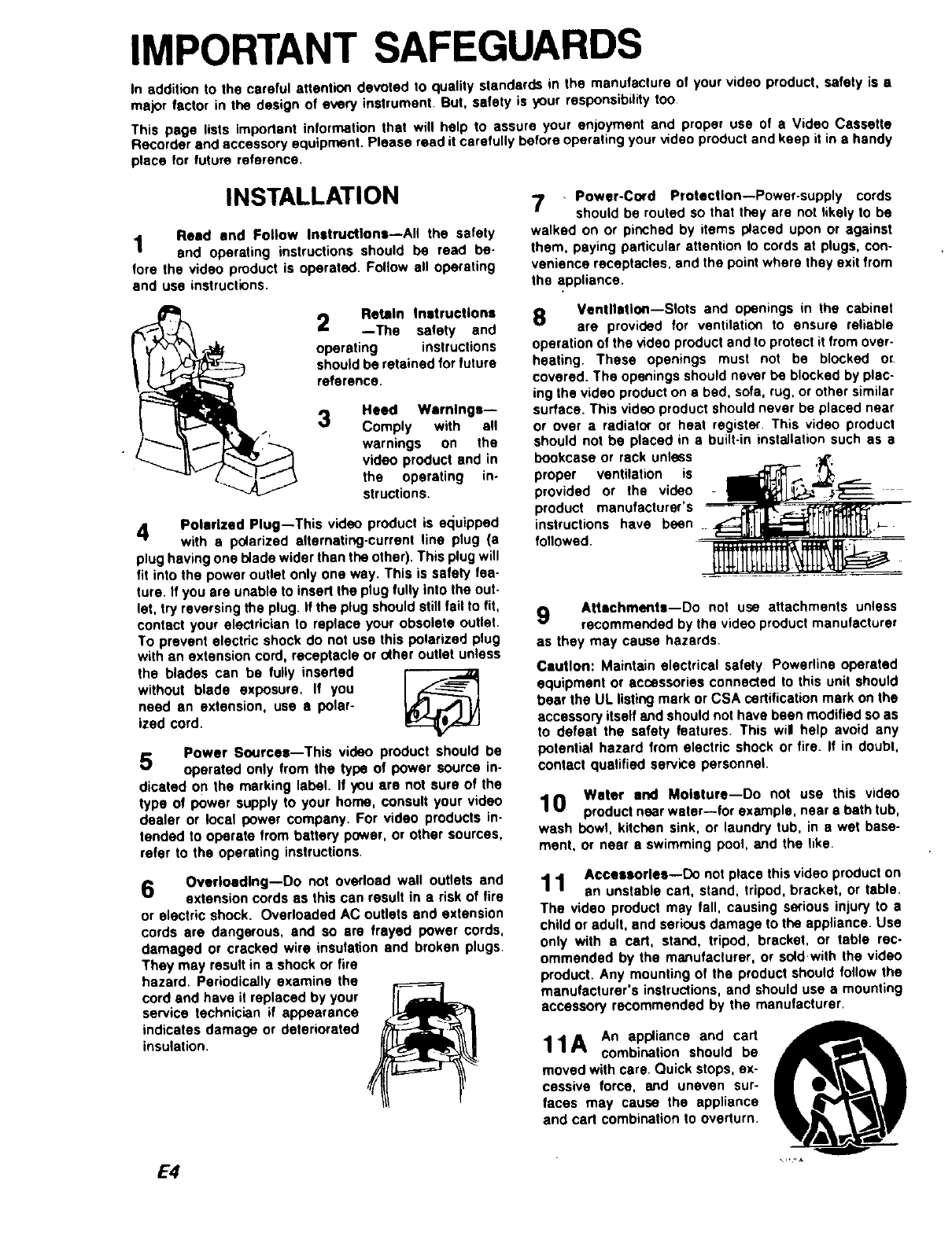
1 Reed end Follow Instructions--All the safety
and operating instructions should be read be-
fore the video product is operated. Follow all operating
and use instructions,
2Retain Instructions
--The safety and
operating instructions
should be retained for future
reference.
Heed Wernlngs--
3Comply with all
/r warnings on the
video product and in
the operating in-
"_A_ structions.
4Polarized Plug--This video product is equipped
with a polarized alternating-currant line plug (a
plug having one I_ade wider than the other). This plug will
fit into the power outlet only one way. This is safety fea-
ture. If you are unable to insert the plug fully into the out-
let, try reversing the plug. If the plug should still fail to fit,
contact your electrician to replace your obsolete outlet.
To prevent elactdc shock do not use this polarized plug
with an extension cord, receptacle or o(her outlet unless
the blades can be fully inserted
without blade exposure, If you
need an extension, use apolar-
ized cord.
Power Soorcee--This video product should be
5 operated only from the type of power source in-
dicated on the marking label. If you are not sure of the
type of power supply to your home, consult your video
dealer or local power company. For video products in.
landed to operate from battery power, or other sources,
refer to the operating instructions.
6Overloading--Do not overload wall outlets and
extension cords as this can result in a risk of fire
or electric shock. Overloaded AC outlets and extension
cords are dangerous, and so ere frayed power cords,
damaged or cracked wire insulation and broken plugs.
They may result in a shock or fire
hazard. Periodically examine the
cord and have it replaced by your
service technician if appearance
indicates damage or deteriorated
insulation.
E4
7,Power-Co_d Protection--Power-supply cords
should be routed so that they are not likely to be
walked on or pinched by items placed upon or against
them, paying particular attention to cords at plugs, con-
venience receptacles, end the point where they exit from
the appliance.
8 Ventilation--Slots and openings in the cabinet
are provided for ventilation to ensure reliable
operation of the video product and to protect it from over-
heating. These openings must not be blocked or-
covered. The openings should never be blocked by plac-
ing the video product on a bad, sofa, rug, or other similar
surface. This video product should never be placed near
or over a radiato¢ or heat register. This video product
should not be placed in abuilt-in installation such as a
bookcase or rack unless
proper ventilation is
provided or the video
product manufacturer's
instructions have been
followed.
9Attachments--Do not use attachments unless
recommended by the video product manufacturer
as they may cause hazards.
Caution: Maintain electrical safety Powerline operated
equipment or accessories connected to this unit should
bear the UL listing mark or CSA certification mark on the
accessory itself and should not have been modified so as
to defeat the safety features. This wil help avoid any
potential hazard from electric shock or fire. If in doubt,
contact qualified service personnel,
Water end Moisture--Do not use this video
10 product near water--for example, near • bath tub,
wash bowl, kitchen sink, or laundry tub, in awet base-
ment, or near • swimming pool, and the like.
Accessories--Do not place this video product on
1 1 an unstable cart, stand, tripod, bracket, or table.
The video product may fall, causing serious injury to a
child or adult, and serious damage to the appliance. Use
only with acart, stand, tripod, bracket, or table rec-
ommended by the manufacturer, or sold with the video
product. Any mounting of the product should follow the
manufacturer's instructions, and should use a mounting
accessory recommended by the manufacturer.
11A An appliance andcart
combination should be
moved with care. Quick stops, ex-
cessive force, and uneven sur-
faces may cause the appliance
and cart combination to overturn.
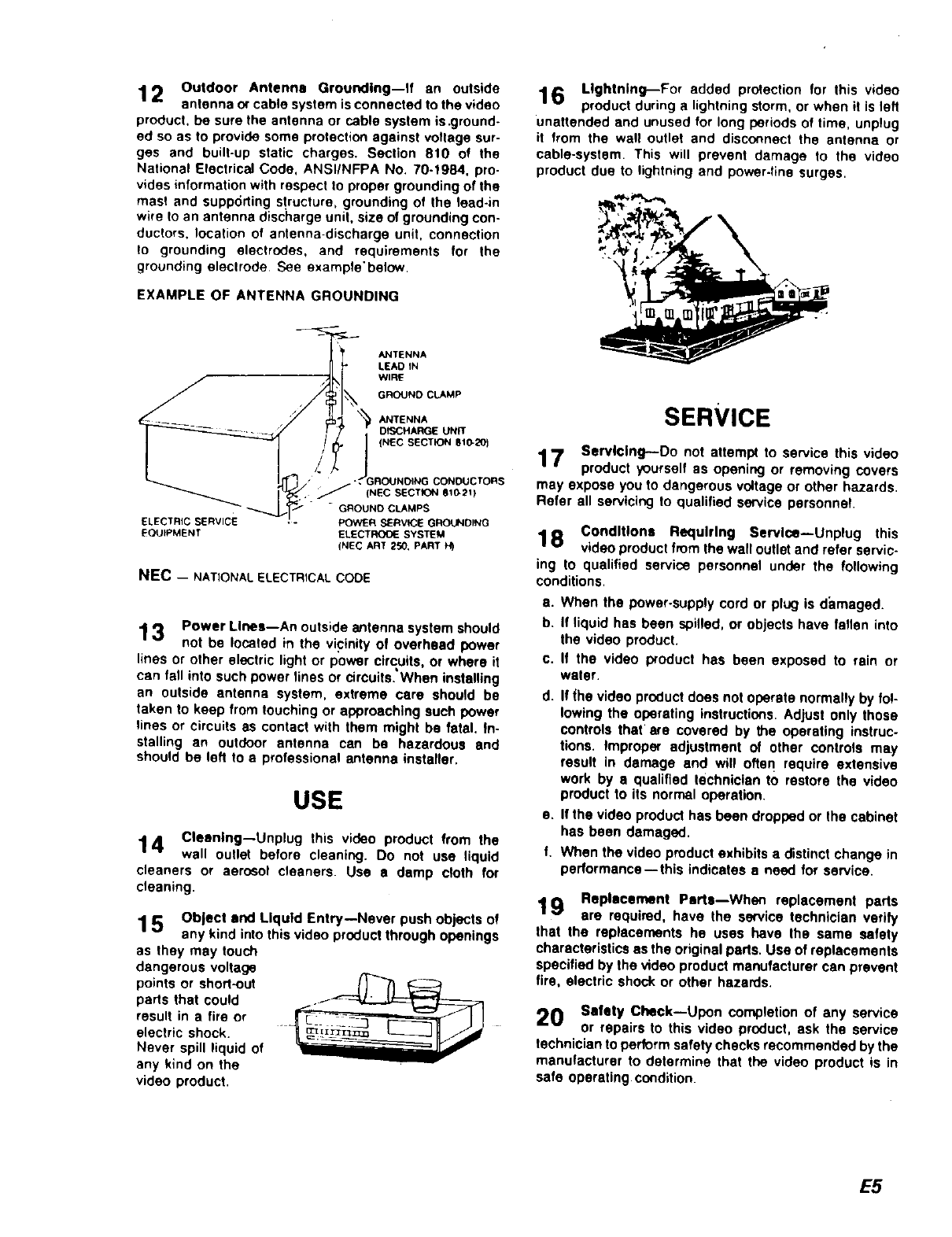
12 Outdoor Antenna Grounding--If an outside
antenna or cable system is connected to the video
product, be sure the antenna or cable system is .ground-
ed so as to provide some protection against voltage sur-
ges and built-up static charges. Section 810 ot the
National Electrical Code, ANSIINFPA No. 70-1984, pro-
vides information with respect to proper grounding of the
masl and supporting structure, grounding of the lead-in
wire to an antenna dis(;harge unit, size of grounding con-
ductors, location of antenna-discharge unit, connection
to grounding electrodes, and requirements for the
grounding eleclrode See exampte'below.
EXAMPLE OF ANTENNA GROUNDING
ANTENNA
LEAD IN
WIRE
GROUND CLAMP
ANTENNA
DISCHARGE UN_
(NEC SECTION Bt_20_
ELECTRIC SERVICE
EQUIPMENT
CONOUCTORS
J'_(NEC SECTION giG21)
"GROUND CLAMPS
POWER SERV_E GROUNDPNG
ELECTRO_.SYSTEM
(NEC ART 250, PART
NEC - NATIONAL ELECTRICAL CODE
13 Power Lines--An outside antenna system should
not be located in the vicinity of overhead power
lines or other electric light or power circuits, or where it
can fall into such power lines or circuits. When installing
an outside antenna system, extreme care should be
taken to keep from touching or approaching such power
tines or circuits as contact with them might be fatal. In-
stalling an outdoor antenna can be hazardous and
should be left to a professional antenna installer.
USE
14 Cleaning--Unplug this video product from the
wall outlet before cleaning. Do not use liquid
cleaners or aerosol cleaners. Use adamp cloth for
cleaning.
15 Object and Liquid Entry--Never push objects of
any kind into this video product through openings
as they may touch
dangerous voltage
points or short-out
parts that could
result in a tire or
electric shock.
Never spill liquid of
any k_nd on the
video product.
16 Lightning--For added protection for this video
product during a lightning storm, or when it Is left
unattended and unused for long periods of time, unplug
it from the wall outlet and disconnect the antenna or
cable-system This will prevent damage to the video
product due to lightning and power-line surges.
SERVICE
17 Servicing--Do not attempt to service this video
product yourself as opening or removing covers
may expose you to dangerous voltage or other hazards.
Refer all servicing to qualified service personnel
Conditions Requiring Service--Unplug this
1 8 video product from the wall outlet and refer servic-
ing to qualified service personnel under the following
conditions.
a. When the power-supply cord or plug is damaged.
b. If liquid has been spilled, or objects have fallen into
the video product.
c. If the video product has been exposed to rain or
water.
d. If (he video product does not operate normally by fo!-
lowing the operating instructions. Adjust only those
controls that' are covered by the operating instruc-
tions. Improper adjustment of other controls may
result in damage and will often require extensive
work by •qualified technician to restore the video
product to its normal operation.
e. If the video product has been dropped or the cabinet
has been damaged.
f. When the video product exhibits a distinct change in
performance--this indicates a need for service.
19 Replacement Pert,,--Whec replacement parts
are required, have the service technician verify
that the replacements he uses have the same safety
characteristics as the original pads. Use of replacements
specified by the video product manufacturer can prevent
fire, electric shock or other hazards.
20 Safety Check--Upon completion of any service
or repairs to this video product, ask the service
technician to perform safety checks recommended by the
manufacturer to determine that the video product is in
safe operating condition.
E5
CONTROLS AND FEATURES
11 12 13 14 15 16 17 18 19 20 "_
t.
I,:7J==
1 234567 89
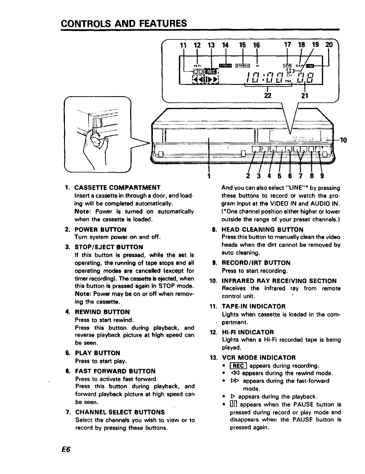
1. CASSE'I-rE COMPARTMENT
Insert a cassette in through a door, and load-
ing will he completed automatically.
Note: Power is turned on automatically
when the cassette is loaded.
2, POWER BUTTON
Turn system power on and off.
3, STOP/EJECT BuI-rON
If this button is pressed, while the set is
operating, the running of tape stops and all
operating modes are cancelled (except for
timer recording). The cassette isejected, when
this button is pressed again in STOP mode.
Note: Power may be on or off when remov-
ing the cassette.
4. REWIND BUTTON
Press to start rewind.
Press this button during playback, and
reverse playback picture at high speed can
be seen.
6. PLAY BU'I-I"ON
Press to start play.
6. FAST FORWARD BUI-I'ON
Press to activate fast forward.
Press this button during playback, and
forward playback picture at high speed can
be seen.
7. CHANNEL SELECT BUT'TONS
Select the channels you wish to view or to
record by pressing these buttons.
,
o
10.
11.
12.
13.
And you can also select "LINE"* by pressing
these buttons to record or watch the pro-
gram input at the VIDEO IN and AUOIO IN.
('One channel position either higher or lower
outside the range of your preset channels.)
HEAD CLEANING BUTTON
Press this button to manually clean the video
heads when the dirt cannot be removed by
auto cleaning.
RECORD/IRT BUTTON
Press to start recording.
INFRARED RAY RECEIVING SECTION
Receives the infrared ray from remote
control unit.
TAPE-IN INDICATOR
Lights when cassette is loaded in the com-
partment,
HI-FI INDICATOR
Lights when a Hi-Fi recorded tape is being
played.
VCR MODE INDICATOR
•_appears during recording.
•<1<)appears during the rewind mode.
•I:>1>appears during the fast-forward
mode.
•I> appears during the playback.
• nil appears when the PAUSE button is
pressed during record or play mode and
disappears when the PAUSE button is
pressed again.
E6
23 24 25
29 28 27 26
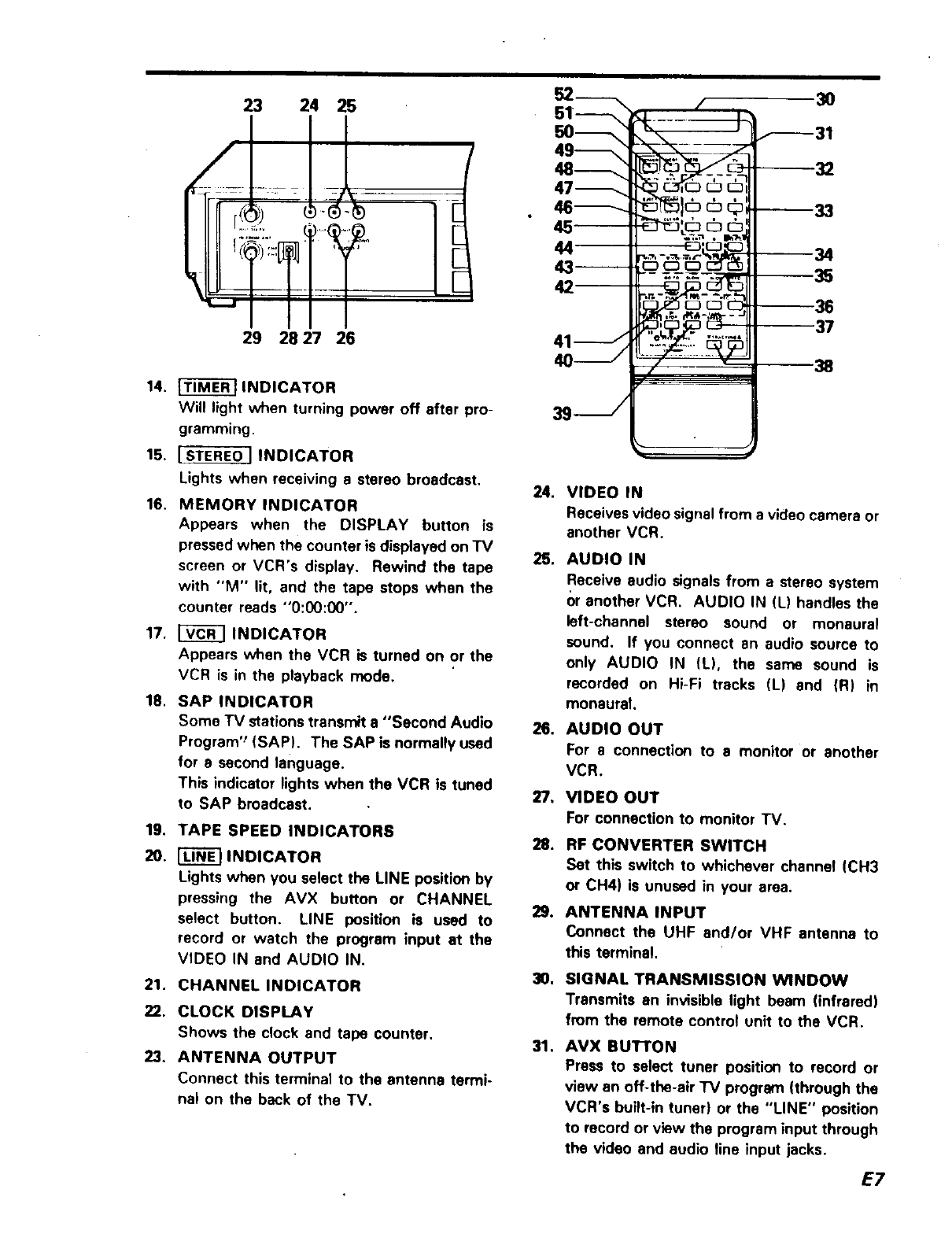
14. _INDICATOR
Will light when turning power off after pro-
gramming.
15, ISTEREO ] INDICATOR
Lights when receiving a stereo broadcast,
16, MEMORY INDICATOR
Appears when the DISPLAY button is
pressed when the counter is displayed on TV
screen or VCR's display. Rewind the tape
with "M" lit, and the tape stops when the
counter reads "O:00:00".
17. [_ INDICATOR
Appears when the VCR is turned on or the
VCR is in the playback mode.
18. SAP INDICATOR
Some TV stations transmit a "Second Audio
Program'_(SAP). The SAP is normally used
for e second language.
This indicator lights when the VCR is tuned
to SAP broadcast.
19. TAPE SPEED INDICATORS
20. _INDICATOR
Lights when you select the LINE position by
pressing the AVX button or CHANNEL
select button. LINE position is used to
record or watch the program input at the
VIDEO IN and AUDIO IN.
21. CHANNEL INDICATOR
22. CLOCK DISPLAY
Shows the c_ock and tape counter.
23. ANTENNA OUTPUT
Connect this terminal to the antenna termi-
na_ on the beck of the TV.
52------_
45--
42
3s- /
--_---31
© --33
--38 37
7" " 38
24. VIDEO IN
Receives video signal from a video camera or
another VCR.
25. AUDIO IN
Receive audio signals from a stereo system
()r another VCR. AUDIO IN (L) handles the
left-channel stereo sound or monaural
sound. If you connect an audio source to
only AUDIO IN (L), the same sound is
recorded on Hi-Fi tracks (L) end (R) in
monaural.
26. AUDIO OUT
For a connection to a monitor or another
VCR.
9,
0,
31.
VIDEO OUT
For connection to monitor TV.
RF CONVERTER SWITCH
Set this switch to whichever channel (CH3
or CH4) is unused in your area.
ANTENNA INPUT
Connect the UHF and/or VHF antenna to
this terminal.
SIGNAL TRANSMISSION WINDOW
Transmits an invisible light beam (infrared)
from the remote control unit to the VCR.
AVX BUTTON
Press to select tuner position to record or
view an off-the-air "IV program (through the
VCR's built-in tuner) or the "LINE" position
to record or view the program input through
the video and audio fine input jacks.
E7
32. "IV BUTTON
First press this button when operating your
TV with this remote control, and then press
the button which corresponds to the func-
tion you want.
33. NUMBER BUTTONS "O" THROUGH "9"
Select any channel {whether or not it is in
the "Tuner Scan List") by pressing two but*
tons. (Press "O" and then "8" for channel 8.)
The number buttons are also used for setting
the clock and programming the timer.
34. CHANNEL SELECT SUTTONS
Same as the buttons on the VCR.
35. SLOW SPEED BUTTONS
During slow playback the slow speed can be
adjusted by pressing the SLOW SPEED
button.
36. VCR CONTROL SUTTONS
These buttons (except for "REC" buttons)
,function same as the buttons on your VCR.
Note: The REC buttons must be pressed
simultaneously to start recording,
37. TAPE SPEED SELECT BUTTON
Recording time using Cassette tape T-160:
EP: 8 hours SP: 2.6 hours
Notes:
* Playback speed automatically cor-
responds with recorded speed.
•This VCR cannot record in LP mode, but
can play LP recorded tapes.
38. TRACKING CONTROL SUTFONS
To minimize noise in playback.
3g. FRAME ADVANCE Bu'n'ON
Press to view tape one frame at s time.
Operates only after PAUSE button has been
pressed.
40. PAUSE BUTTON
Press to pause during recording or playback.
41. SLOW BUI-I"ON
Allows you to view a picture at slow speed.
42. GO-TO/INDEX BUTTON
Press this button to search for the scene you
want to view using the counter GO-TO or
INDEX feature.
43. TV CONTROL BUTTONS
Used for controlling the TV.
E8
4.
5,
7.
0,
100lENT BUTTON
Used to select "IV or CATV channels.
Press "100", "2", "3" in this order to select
channel 123. Press "100", "0" and "5'" for
channel 105.
DISPLAy BUTTON
1st Press .... Calls up the mode display on
TV screen,
2nd Press {before display disappeears)
.... The display on "IV screen disappears ex-
cept for "Linear Time Counter",
Also changes the VCR's display from the
clock to the counter,
3rd Press .... The counter memory "M" ap-
pears on "IV screen and in VCR's display,
4th Press .... Clears the display on "IV
screen, Also changes the VCR's display
from the counter to the clock.
CLEAR BUTTON
Used for programming the timer.
And also used for counter reset button.
EJECT BUTTON
When this button is pressed in modes other
than recording, the tape stops, and the cas-
sette is ejected.
INTELASCAN GUIDE BUTTON
Press this button to use the Intelascan fea-
ture. (See page 2 for details.)
VCR/TV SELECT BuTrON
Selects the signal to be viewed.
The VCR indicator comes on when the unit
is in VCR mode and the signal received by
the VCR is displayed on the TV screen.
With the switch in the "IV position {indicator
light off) the broadcast signal is received
directly by your TV set. When the VCR
power is turned off, the VCR automatically
switches to "TV".
POWER BUTTON
Press to turn VCR on, Press again to turn
VCR off,
51. VCR1 BUTTON
First press this button when operating the
VCR with this remote control and then press
the button which corresponds to the func-
tion you want,
52, VCR 2 BUTTON
Press this button when using another Hitachi
VCR and operating the remote control
provided to control the two VCRs.
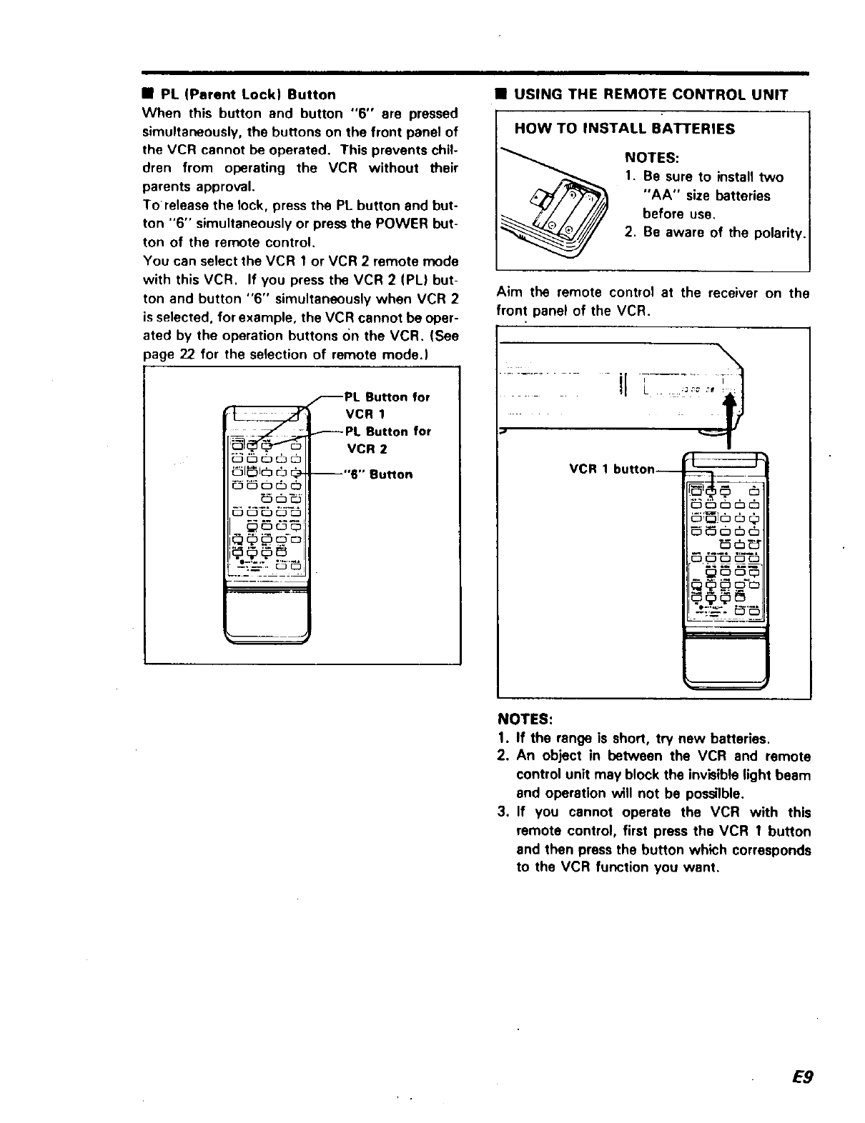
•PL (Parent Lock) Button
When this button and button "6" ere pressed
simultaneously, the buttons on the front panel of
the VCR cannot be operated. This prevents chil-
dren from operating the VCR without their
parents approval.
To release the lock, press the PL button and but-
ton "6" simultaneously or press the POWER but-
ton of the remote control.
You can select the VCR 1or VCR 2 remote mode
with this VCR. If you press the VCR 2 (PL) but-
ton and button "6" simultaneously when VCR 2
is selected, for example, the VCR cannot be oper-
ated by the operation buttons On the VCR. (See
page 22 for the selection of remote mode.)
_PL Button for
VCR 1
_PL Button for
- . VCR 2
_1_1(_ _ _- --"6" Button
__-. _'_
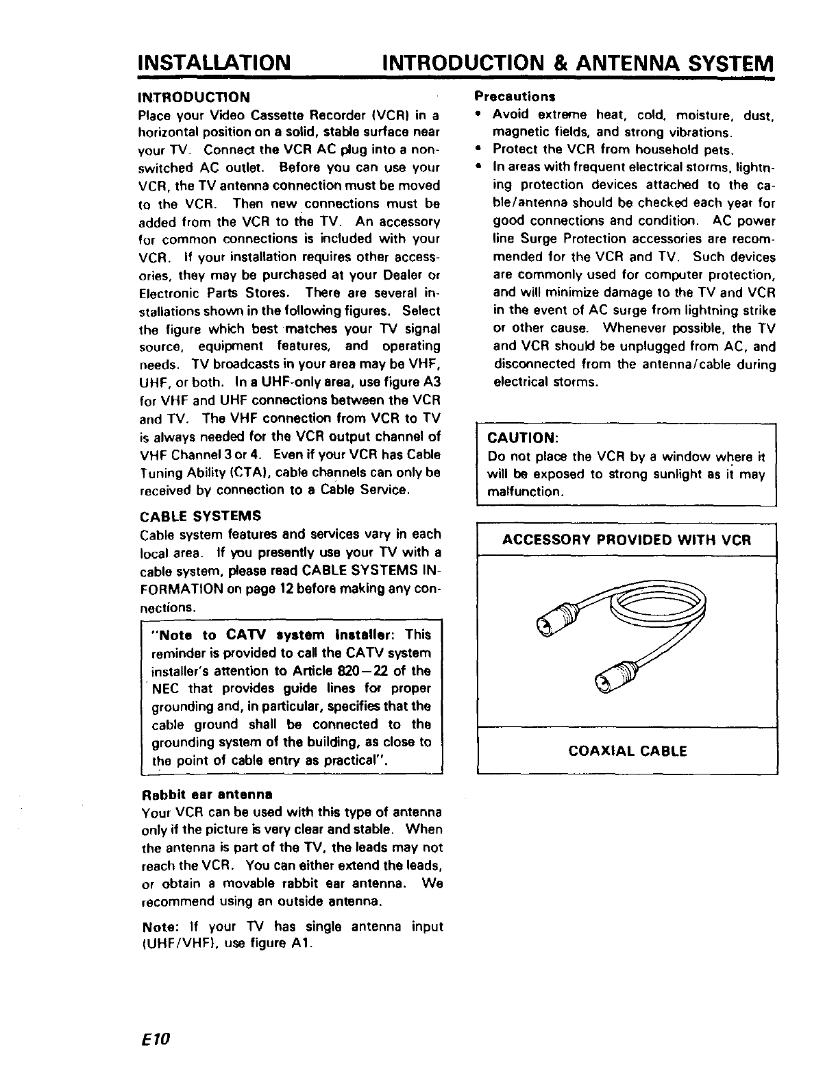
•USING THE REMOTE CONTROL UNIT
IHOW TO BATI'ERIES
INSTALL
NOTES:
1. Be sure to install two
"AA" size batteries
before use.
2. Be aware of the polarit_
Aim the remote control at the receiver on the
front panel of the VCR.
...... ir 7.....
VCR 1 button--
_,.N
_ c_c__:
NOTES:
1. If the range is short, try new batteries.
2. An object in between the VCR and remote
control unit may block the invisible )ight beam
and operation will not be possilble.
3. If you cannot operate the VCR with this
remote contro), first press the VCR 1 button
end then press the button which corresponds
to the VCR function you want.
E9
INSTALLATION INTRODUCTION & ANTENNA SYSTEM
INTRODUCTION
Place your Video Cassette Recorder (VCR) in a
horizontal position on a solid, stable surface near
your TV. Connect the VCR AC plug into a non-
switched AC outlet. Before you can use your
VCR, the TV antenna connection must be moved
to the VCR. Then new connections must be
added from the VCR to the TV. An accessory
for common connections is included with your
VCR. If your installation requires other access-
ories, they may be purchased at your Dealer or
Electronic Parts Stores. There are several in-
stallations shown in the following figures. Select
the figure which best matches your "IV signal
source, equipment features, and operating
needs. TV broadcasts in your area may be VHF,
UHF, or both. In a UHF-only area, use figure A3
for VHF and UHF connections between the VCR
and TV. The VHF connection from VCR to TV
is always needed for the VCR output channel of
VHF Channel 3 or 4. Even if your VCR has Cable
Tuning Ability (CTA), cable channels can only be
received by connection to e Cable Service.
CABLE SYSTEMS
Cable system features and services vary in each
local area. If you presently use your TV with a
cable system, please read CABLE SYSTEMS IN-
FORMATION on page 12 before making any con-
nections.
"Note to CATV system installer: This
reminder is provided to call the CATV system
nstaller's attention to Article 820-22 of the
P4EC that provides guide lines for proper
grounding and, in particular, specifies that the
cable ground shall be connected to the
grounding system of the building, as close to
the point of cable entry as practical".
I
Precautions
•Avoid extreme heat, cold, moisture, dust,
magnetic fields, and strong vibrations.
•Protect the VCR from household pets.
•In areas with frequent electri(:al storms, lightn-
ing protection devices attached to the ca-
ble/antenna should be checked each year for
good connections and condition. AC power
line Surge Protection accessories are recom-
mended for the VCR and TV. Such devices
are commonly used for coml_Jter protection,
and will minimize damage to the TV and VCR
in the event of AC surge from lightning strike
or other cause. Whenever possible, the TV
and VCR should be unplugged from AC, and
disconnected from the antenna/cable during
electrical storms.
CAUTION:
Do not place the VCR by a window where it
will be exposed to strong sunlight as it may
malfunction.
ACCESSORY PROVIDED WITH VCR
COAXIAL CABLE
Rabbit ear antenna
Your VCR can be used with this type of antenna
only if the picture is very clear and stable. When
the antenna is part of the TV, the leads may not
reach the VCR. You can either extend the leads,
or obtain a movable rabbit ear antenna. We
recommend using an outside antenna.
Note: If your "IV has single antenna input
(UHF/VHF), use figure AI.
EIO
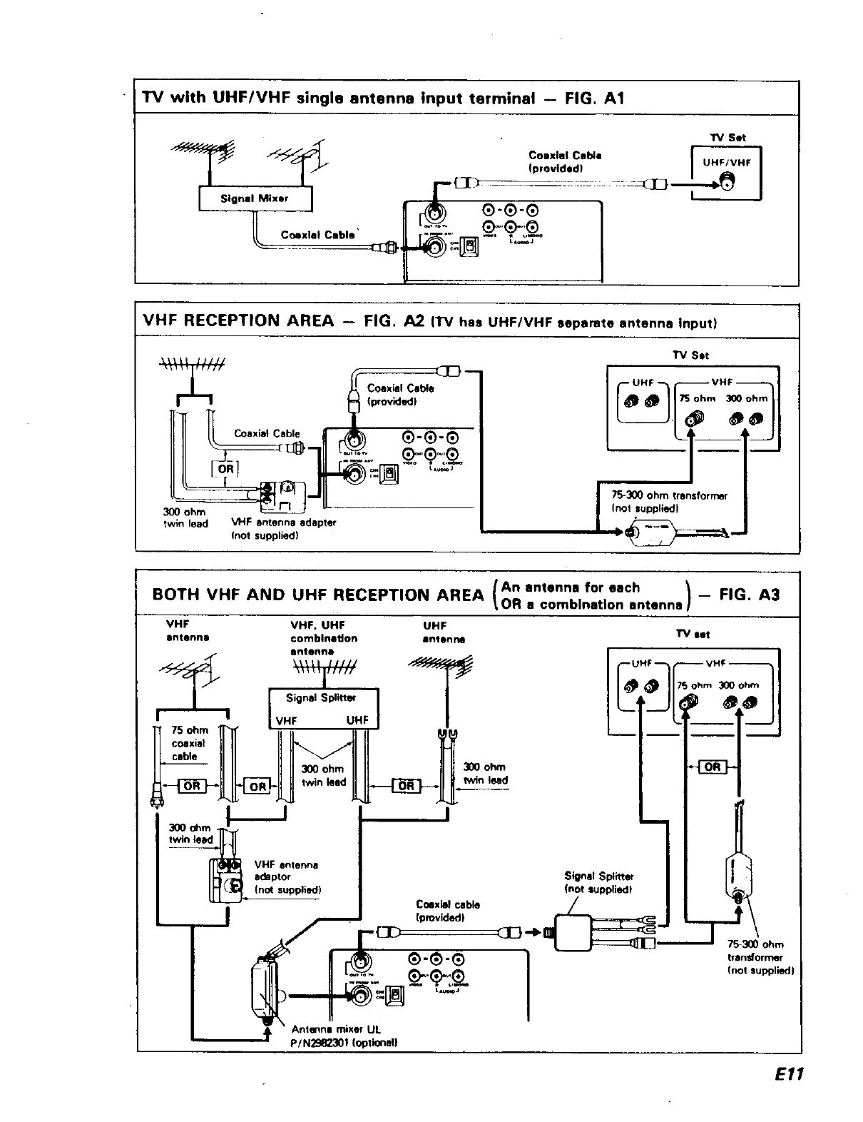
TV with UHFIVHF single antenna Input terminal -- FIG. A1
7 io.7,71
_o "=[_-"_-_-
VHF RECEPTION AREA - FIG. A2 (l"V has UHF/VHF separate antenna Input)
I__ 'b'°n_ __'_
IIII o___-J_711 _.:'_:.. _'_.7_
300 ohm _--
twin lead VHF antenna adapter
(not supplied)
17/ Set
I 75-300 ohm transformer
(not supplied)
/An antenna for each _FIG. A3
BOTH VHF AND UHF RECEPTION AREA \OR a comblnatlon antenna] --
VHF VHF. UHF UHF
antenna €omblnadon antenna
Bntenno
Signal Splitteq
__J
UHF I
Coaxial cable
Iprovided)
300 ohm
lwin laid
UHF --
Signal Splitter
Inot luppliedl
_E} --Ib _ '-_7_300 ohm
transformer
(not suppliedJ
Antenna mixer UL
p/N2982301 (optional}
E11
INSTALLATION CABLE SYSTEM
CABLE SYSTEM INFORMATION
Cable systems vary in features and services. The
information and figures which follow cover most
installations. If you need information about other
installations, please write to Service at the
nearest Hitachi address listed at the back of this
manual. The tuning abilities of your VCR and
the type of cable service you have will determine
what connections cart be used. The VCR Tuning
Range is listed in the rear of this Manual. VCRs
with Cable Tuning Ability (CTA) are able to tune
channels listed for CATV. Most cable services
will be one of the following four types.
1. Basic Cable: Apartment buildings and planned
communities may provide this type of ser-
vice. No channel selection Cable Box is used
with the TV. All channels are received using
VHF channels 2- 13. With this system, no
special connections or operating procedures
are needed. Connect the VCR and TV as
shown in figure C1.
2. Extended Cable -- A Cable Box is used for TV
Channel Selection: The 1_/ is usually set to
channel 3 or 4, and all channel selection is per-
formed using the cable company supplied
Cable Box. In this type of system, no extra
cost channels are available, and no channels
are scrambled.
A CTA VCR can select channels on this sys-
tem without a Cable Box, if the channels on
the cable are in the VCR tuning range. The
Cable Box may still be needed for the TV, un-
less the VCR is used as a cable converter.
You can use figure C1, C2, or C3 for Extended
Cable connection. Connections in C1 and C2
need no additional accessories. The connec-
tion of figure C3 allows recording and watch-
ing different programs but operation is more
complicated.
3. Extended Cable With Extra Cost Channels --
No Scrambled Channels On System-Cable
Converter Box Used For TV: In this type of ca-
ble system, extra cost channels are added or
deleted before the cable enters the customer
home.
If a CTA VCR and CTA TV am used, a Cable
Box is not needed. Connections can be made
as shown in figure C1. If anon-CTA TV is
used with a CTA VCR, either figure C2 or C3
can be used. If both non-CTA VCR and TV
are used, figure C2 must be used.
E/2
4. Extended Cable With Extra Cost Channels --
Scrambled Channels on System-Cable
Descrambler/Converter Box Used For TV: In
this type of system the cable company sup-
plied Box must always be used to get proper
reception of Extra Cost channels. All Extra
Cost channels on the cable are scrambled, but
the Cable Box unscrambles any that you pay
extra to view. Channels included in the basic
cable service fee are usually not scrambled,
and can be tuned by a CTA VCR or CTA TV.
ADDITIONAL INFORMATION
When, any type of scrambling is used for Extra
Cost channels, the Cable Box must be used to
view or record those channels. A CTA VCR
does not include unscrambling ability. That abili-
ty is restricted to only cable company supplied
equipment. On cable systems with scrambled
channels, you have several choices. Among
them are:
a. Recording and watching only channels selec-
ted by the Cable Box (see figure C21.
b. Adding a second cable company supplied
Box.
c. Adding switches to allow either recording and
watching the channel selected by the Cable
Box or recording achannel which is non-
scrambled while watching another channel
selected by the Cable Box (see figure C3).
Two Cable Systems: In some areas, two cables
are used as inputs to the Cable Box. One cable
may contain mostly non-scrambled channels, the
other mostly Extra Cost scrambled channels.
When you have a two-cable system, the cable
with non-scrambled channels you wish to record
(Cable A or Cable B) can usually be connected as
in figure C3. One Cable can be connected di-
rectly, or both cables can be accessed by using
the Cable Box. If you need to use both cables
directly, write Hitachi service for a connection
diagram.
CAUTION: Only high quality, low loss switches
and splitters should be used. All connections
must be with shielded Coax cable. If your added
connections degrade the performance of Extra
Cost channels, all connections should be re-
moved. The circuit of figure C2 should cause
least signal loss. If even the circuit of figure C2
is not satisfactory, consult your cable company
about installation.
CABLESYSTEMVCROPERATION
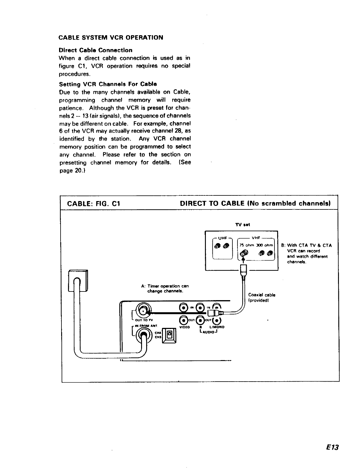
Direct CableConnection
Whena directcableconnectionis usedas in
figure C1, VCR operationrequiresno special
procedures.
SettingVCRChannelsFor Cable
Due to the many channels available on Cable,
programming channel memow will require
patience. Although the VCR is preset for chan-
nels 2 - 13 (air signals), the sequence of channels
may be different on cable. For example, channel
6 of the VCR may actually receive channel 28, as
identified by the station. Any VCR channel
memory position can be programmed to select
any channel. Please refer to the section on
presetting channel memory for details, (See
page 20.)
CABLE: FIG. C1 DIRECT TO CABLE (No scrambled channels)
ElA: Timer operation can
change channels.
@
IN FII()M ANT
¢M3
tl
set
®oo,®oo,
VIDEO _LIMONO
LAuoloJ
COaxial cable
(provided)
B: With CTA TV a CTA
VCR can record
and watch different
channels.
E13
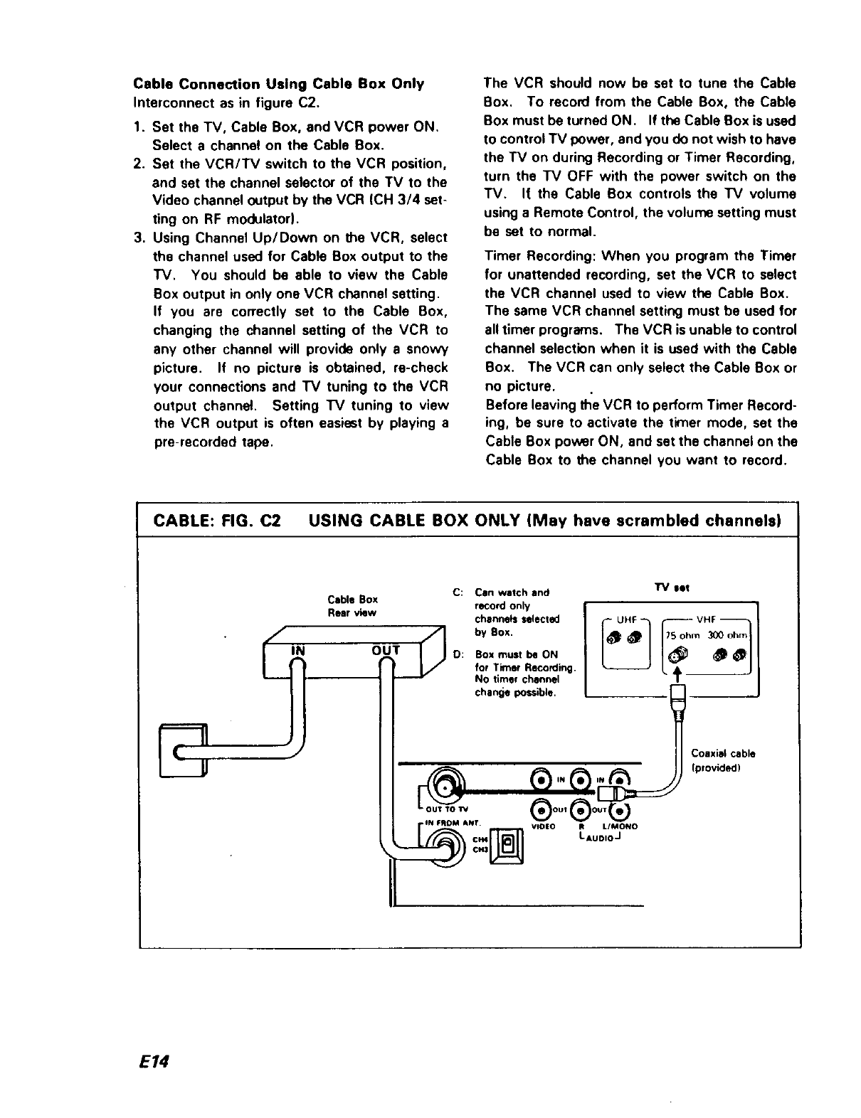
Cable Connection Using Cable Box Only
Interconnect as in figure C2.
1. Set the TV, Cable Box, and VCR power ON,
Select a channel on the Cable Box.
2. Set the VCR/TV switch to the VCR position,
and set the channel selector of the TV to the
Video channel output by the VCR (CH 3/4 set-
ting on RF modulator).
3. Using Channel Up/Down on the VCR, select
the channel used for Cable Box output to the
TV. You should be able to view the Cable
Box output in only one VCR channel setting.
If you are correctly set to the Cable Box,
changing the channel setting of the VCR to
any other channel will provide only a snowy
picture. If no picture is obtained, re-check
your connections and TV tuning to the VCR
output channel. Setting "IV tuning to view
the VCR output is often easiest by playing a
pre-recorded tape.
The VCR should now be set to tune the Cable
Box. To reco_ from the Cable Box, the Cable
Box must be turned ON. If the Cable Box is used
to control TV power, and you do not wish to have
the TV on during Recording or Timer Recording,
turn the TV OFF with the power switch on the
TV. It the Cable Box controls the "IV volume
using a Remote Control, the volume setting must
be set to normal.
Timer Recording: When you program the Timer
for unattended recording, set the VCR to select
the VCR channel used to view the Cable Box.
The same VCR channel setting must be used for
all timer programs. The VCR is unable to control
channel selection when it is used with the Cable
Box. The VCR can only select the Cable Box or
no picture.
Before leaving the VCR to perform Timer Record-
ing, be sure to activate the timer mode, set the
Cable Box power ON, and set the channel on the
Cable Box to the channel you want to record.
CABLE: FIG. C2 USING CABLE BOX ONLY (May have scrambled channels)
C: Can watch and
Cable Box
Rear view record only
channels selected
_'_i by BOX.
D: BOX must be ONOUT J/ for Timer Recording.
No timer channel
change possible.
TV let
UHF VHF
tN F_DM ANT VfO|O R LIMONO
cm LAuoIoJ
Coaxial cable
(provided)
E/4
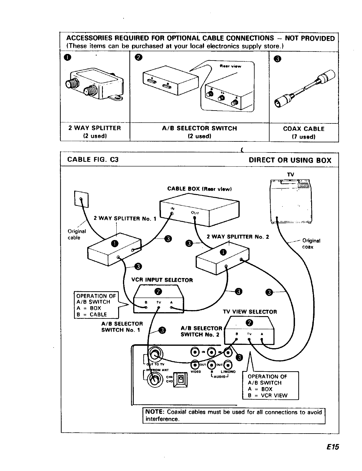
ACCESSORIES REQUIRED FOR OPTIONAL CABLE CONNECTIONS - NOT PROVIDED
(These items can be purchased at your local electronics supply store,)
O O
2 WAY SPLI'I-rER
(2 used)
A/B SELECTOR SWITCH
12 used)
COAX CABLE
(7 used)
CABLE FIG. C3
(
DIRECT OR USING BOX
"IV
CABLE BOX fReer view)
f
Original
cable
2 WAY SPLII-FER No. t
2 WAY SPLITTER No. 2
OCOSX
VCR INPUT SELECTOR
OPERATION
A/B SWITCH
A=BOX
B = CABLE
A/B SELECTOR
SWITCH No, 1
•-0
"IV VIEW SELECTOR
O
A/B SELECTOR
SWITCH No. 2 e rv A
®
VlO|O R L/MONO
LAUOIOJ OPERATION OF
A/B SWITCH
A = BOX
B = VCR VIEW
I NOTE: Coaxial cables must be used for all connections to avoid l
interference, ]
E15
Cable Connection Direct or Using Cable Box
When using figure C3 with a non-scrambled
cable system, the VCR Input Selector Switch
No. 1 and the 2 Way Splitter No. 2 can be omit-
ted, along with the coax interconnecting the
two. Connect the VCR Input directly to splitter
No. 1, and the cable box Output directly to A/B
switch No. 2.
Function of Acce6sorie$
2 Way Splitter No. 1: Divides the cable signal so
the signal is provided to the VCR and the Cable
Box.
A/B Selector Switch No. 1, VCR Recording
Input Selector: Used to select the Source for
VCR use. In one position, the cable can be
recorded directly. In the other position, the VCR
can record the Cable Box.
2 Way Splitter No. 2: Divides the signal from
the Cable Box so the VCR can record it, or it can
be viewed on "IV.
A/B Selector Switch No. 2, TV Viewlng
Switch: Used to allow the "IV to view the Cable
Box while the VCR is recording Direct cable
sources. In the other position, TV can view VCR
Recording or Playing. (VCR/TV switch of video
tape recorder must be in VCR mode,)
Operation: After completing connections, set
A/B No, 2 to A position. Verify cable channels
to TV. In this position, the TV and Cable Box
can be used as previously, except when making
unattended recording of the Cable Box. Then
the Cable Box power must remain ON. To view
what the VCR is Recording or playing, set the
switch to position B. Tune the TV to the VCR
output channel, and set the VCR/TV Switch to
the VCR mode.
Operation of VCR
When the VCR Input Selector Switch A/B No. 1
is in position A, the VCR can record the Cable
Box. One channel position of the VCR should be
set to tune the Cable Box. Channel position 01
is recommended. Set the VCR as in the section
for Using Cable Box Only, when using position A.
When the A/B No. 1 is in position B, the VCR
operates as indicated in Direct Connection to
Cable. Refer to Setting channels for Cable.
Remember that when making aTimer Recording
using the Cable Box, the Cable Box channel must
beprogrammed into the Timer, the A/B No. 1
Switch must be set to A, and Cable Box power
must be left ON. When recording the Cable
directly, be sure to set the switch to position B.
The VCR cannot select between the Cable Box
and Direct Cable inputs, so unattended record-
ings of both sources alternately should not be
programmed unless someone is available to
change the setting of switch A/B No. Iduring
Timer operation.
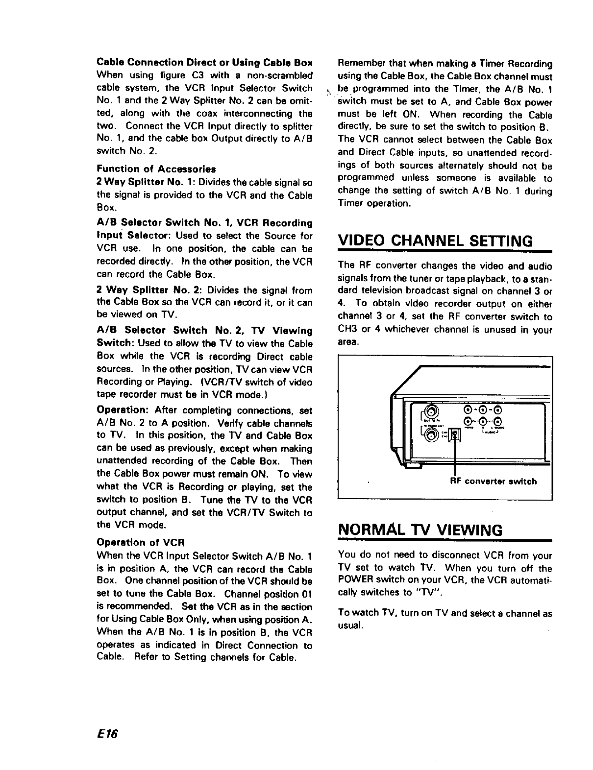
VIDEO CHANNEL SETTING
The RF converter changes the video and audio
signals from the tuner or tape playback, to astan-
dard television broadcast signal on channel 3 or
4. To obtain video recorder output on either
channel 3 or 4, set the RF converter switch to
CH3 or 4 whichever channel is unused in your
area.
/
RF converter switch
NORMAL TV VIEWING
You do not need to disconnect VCR from your
TV set to watch TV. When you turn off the
POWER switch on your VCR, the VCR automati-
cally switches to "'IV".
To watch TV, turn on TV and select a channel as
usual.
E16
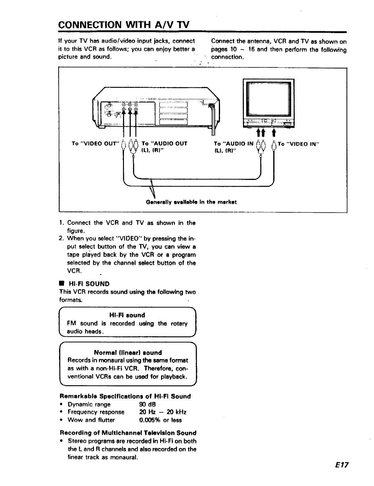
CONNECTION WITH A/V TV
If your TV has audio/video input jacks, connect Connect the antenna, VCR and TV as shown on
it to this VCR as follows; you can enjoy better e pages 10 -16 and then perform the following
picture and sound, connection.
-_, .
III
"VIDEO OUT" _r_/_To "AUDIO OUT
To
(Lh In)"
Generally available In the market
I ......... 1
tt t
To "AUDIO IN _t
ILl, IR)" To "VIDEO IN"
1. Connect the VCR and TV as shown in the
figure.
2. When you select "VIDEO" by pressing the in-
put select button of the IV, you can view e
tape played back by the VCR or a program
selected by the channel select button of the
VCR.
•Hi-FI SOUND
This VCR records sound using the following two
formats.
HI-Fi sound
FM sound is recorded using the rotary
audio heads.
Normal (linear) sound
Records in monaural using the same format
as with a non-Hi-Fi VCR. Therefore, con-
ventional VCRs can be used for playback.
Remarkable Specifications of HI-FI Sound
• Dynamic range 90 dB
•Frequency response 20 Hz -- 20 kHz
•Wow and flutter 0.005% or less
Recording of Multlchennel Television Sound
•Stereo programs are recorded in Hi-Fi on both
the Land R channels and also recorded on the
linear track as monaural.
E17
SETTING THE CLOCK
Things to know before starting
• The clock uses the 12-hour system.
(Be aware of AM and PM.)
•When you first plug in your VCR. the clock
will read ":"
•While you are setting the clock, the
"menu" display on the "IV screen will
prompt you through the procedures.
• If you press a wrong digit, pressthe CLEAR
button repeatedly until the digit to be cor-
rected flashes and then enter the correct
digit.
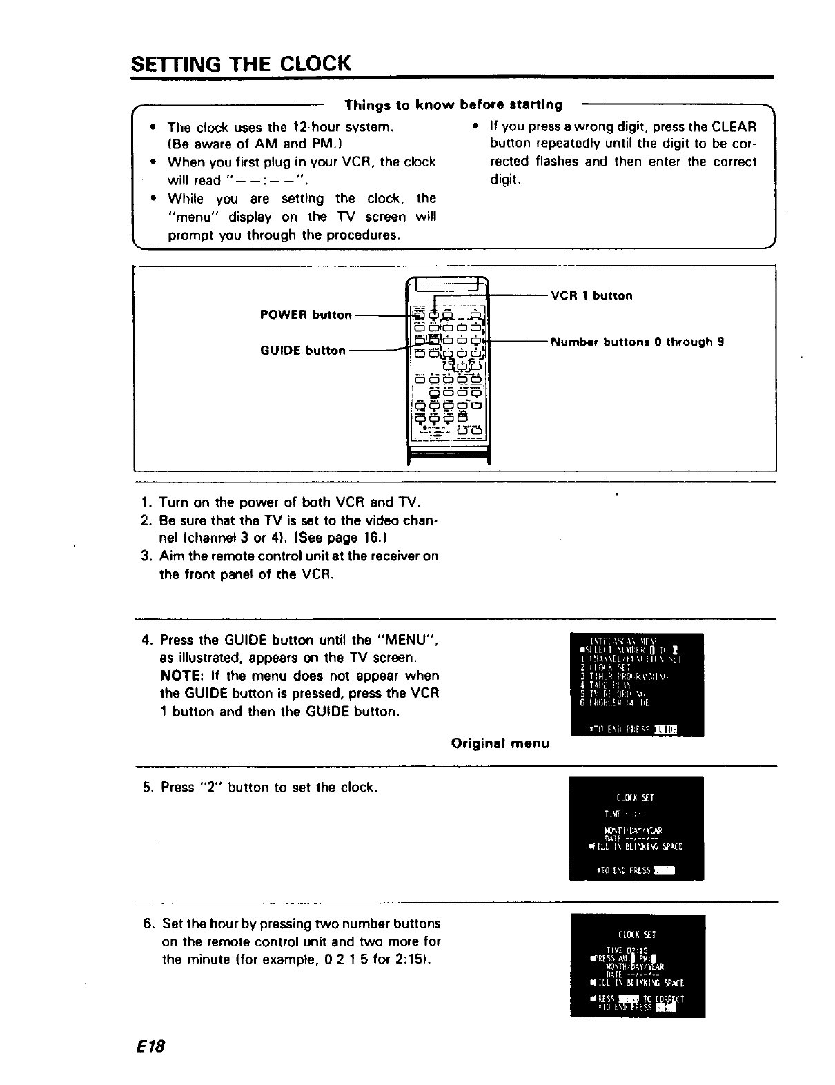
POWER button--
GUIDE button
_=====m=
VCR t button
Number buttons 0 through 9
1. Turn on the power of both VCR and TV.
2, Be sure that the TV is set to the video chan-
nel Ichannet 3 or 4). (See page 16.)
3. Aim the remote control unit at the receiver on
the front panel of the VCR.
4. Press the GUIDE button until the "MENU",
as illustrated, appears on the TV screen.
NOTE: If the menu does not appear when
the GUIDE button is pressed, press the VCR
1 button and then the GUIDE button.
Original menu
5. Press "2" button to set the clock.
6. Set the hour by pressing two number buttons
on the remote control unit and two more for
the minute (for example, O2 15for 2:15),
E18
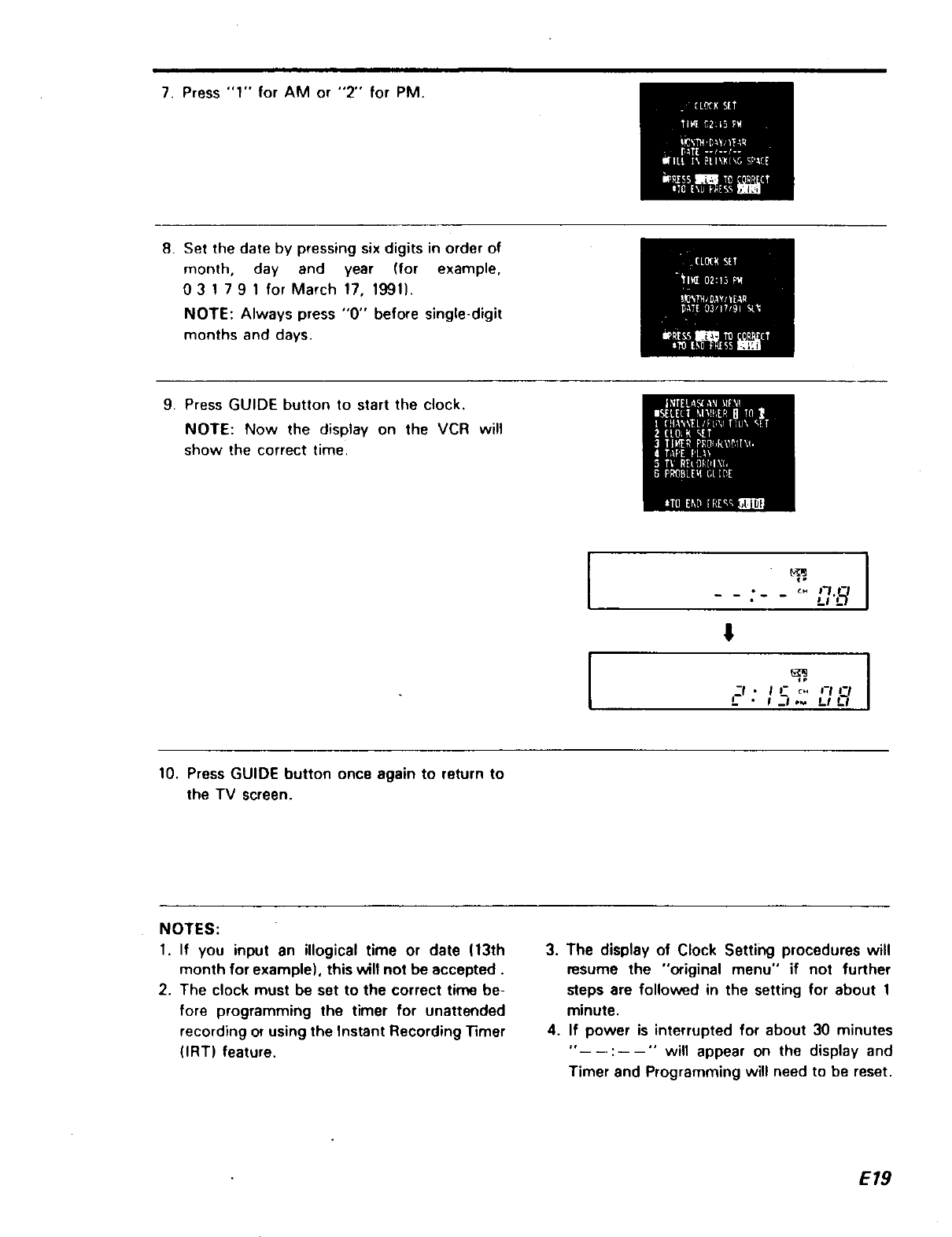
7. Press "1" for AM or "2" for PM.
8. Set the date by pressing six digits in order of
month, day and year (for example,
03 1 791 for March 17, 1991).
NOTE: Always press "0" before single-digit
months and days.
9. Press GUIDE button to start the clock.
NOTE: Now the display on the VCR will
show the correct time.
I
I
° I
•<M:_7.8
!l
:, e,_-°. :7,'_,'
10. Press GUIDE button once again to return to
the TV screen.
NOTES:
I. If you input an illogical time or date (13th
month for example), this will not be accepted.
2. The clock must be set to the correct time be-
fore programming the timer for unattended
recording or using the Instant Recording Timer
(IRT) feature.
3. The display of Clock Setting procedures will
resume the "original menu" if not further
steps are followed in the setting for about 1
minute.
4. If power is interrupted for about 30 minutes
":"will appear on the display and
Timer and Programming will need to be reset.
E19
CHANNEL TUNING
The automatic programming feature makes it easy
and convenient to program the TV station into the
tuner's memory.
Automatic programming is usually a "one-time"
procedure, but you will need to repeat it if you
move to a location that has different channels, or
if the power is interrupted for about 30 minutes.
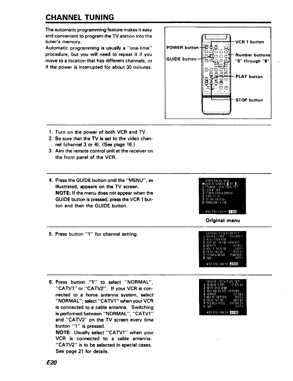
POWER button-
GUIDE button_ ....._cS©I
cJ _ Jl
-VCR 1 button
- Number buttona
"0" through "9"
PLAY button
STOP button
1. Turn on the power of both VCR and "IV.
2. Be sure that the TV is set to the video chan-
nel (channel 3 or 4). (See page 16.)
3. Aim the remote control unit at the receiver on
the front panel of the VCR.
4. Pressthe GUIDE button unSI the "MENU", as
illustrated, appears on the TV screen,
NOTE: If the menu does not appear when the
GUIDE button is pressed, pressthe VCR 1but-
ton and then the GUIDE button.
5. Press button "1" for channel setting.
6. Press button "1" to select "NORMAL",
"CATVI" or "CATV2". If your VCR is con-
nected to a home antenna system, select
"NORMAL"; select "CATVI" when your VCR
is connected to e cable antenna. Switching
is performed between "NORMAL", "CATVI"
and "CATV2" on the TV screen every time
button "1" is pressed.
NOTE: Usually select "CATVI" when your
VCR is connected to a cable antenna.
"CATV2" is to be selected in special cases.
See page 21 for details.
E20
Original menu
7. Press"2" button.
The tuner will automatically cycle through all
available channels in the area and place them
in the tuner's memory. It takes about 2 - 3
minutes.
The channel number will stop changing when the
tuner is finished cycling. Programming is now
completed.
You can select the active channels by pressing the
CHANNEL select buttons.
•Eliminating unwanted preset channels
You may want to have only a few favorite chan-
nels in the tuner's memory so you can select them
more quickly with the CHANNEL select button.
Occasionally automatic programming may include
a vacant channel in the tuner's memory if there
happened to be some sort of "noise" or "stray sig-
nal" on the channel when the tuner was
programmed. This procedure explains how to de-
lete any unwanted channels from the tuner's
memory.
•Adding channels to the tuner's memory
You may have deleted a channel from the tuner's
memory and want to put it back. Occasionally
automatic programming may "miss" an active
channel because the signal is very weak or because
the channel happened to be "off the air" when the
tuner was programmed. Use thisprocedure to add
any channel in the memory.
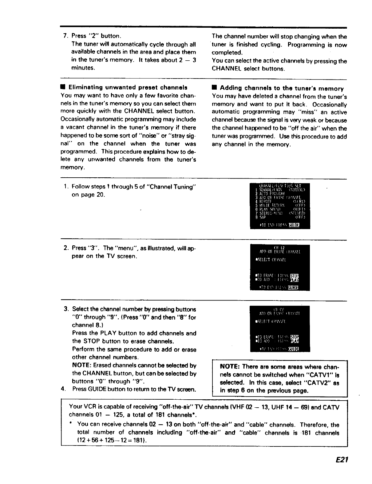
1. Follow steps 1through 5 of "Channel Tuning"
on page 20.
2. Press"3". The "menu", as illustrated, will ap-
pear on the TV screen.
3. Select the channel number by pressingbuttons
"0" through "9". (Press "0" and then "8" for
channel 8.)
Press the PLAY button to add channels and
the STOP button to erase channels.
Perform the same procedure to add or erase
other channel numbers.
NOTE: Erased channels cannot be selected by
the CHANNEL button, but can be selected by
buttons "0" through "9".
4. PressGUIDE button to return to the'IV screen.
i
NOTE: There ere some areas where chan-
nels cannot be switched when "CATVI" is I
selected. In this case, select "CATV2" as
In step 6 On the previous page.
Your VCR is capable of receiving "off-the-air" TV channels (VHF 02 -- 13, UHF 14 - 69) and CATV
channels 01 -- 125, a total of 181 channels'.
" You can receive channels 02 -- 13 on both "off-the-air" and "cable" channels. Therefore, the
total number of channels including "off-the-air" and "cable" channels is .181 channels
(12 + 56 + 125-- 12 =181).
E21
VCR FUNCTION SETTING
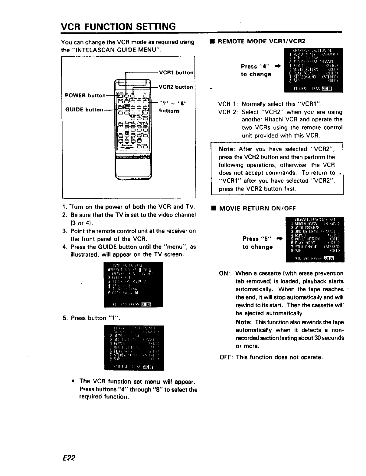
You can change the VCR mode as required using
the "INTELASCAN GUIDE MENU".
•REMOTE MODE VCRI/VCR2
POWER button--
GUIDE button_
VCR1 burton
--VCR2 button
-"t" - ",,"
_,_, _.,_- buttons
-_...'_____...._'_
Press "'4"° ,,I.
to change
VCR 1: Normally select this "VCRI".
VCR 2: Select "VCR2" when you are using
another Hitachi VCR and operate the
two VCRs using the remote control
unit provided with this VCR.
Note: After you have selected "VCR2",
press the VCR2 button and then perform the
following operations; otherwise, the VCR
does not accept commands. To return to .
"VCRI" after you have selected "VCR2",
press the VCR2 button first.
1. "Turn on the power of both the VCR and TV.
2. Be sure that the TV is set to the video channel
(3 or 4).
3. Point the remote control unit at the receiver on
the front panel of the VCR.
4. Press the GUIDE button until the "menu", as
illustrated, will appear on the TV screen.
•MOVIE RETURN ON/OFF
Press "5" "_
to change
5. Press button "1".
ON: When a cassette (with erase prevention
tab removed) is loaded, playback starts
automatically. When the tape reaches •
the end, it will stop automatically and will
rewind to its start. Then the cassette will
be ejected automatically.
Note: This function alsorewindsthe tape
automatically when it detects a non-
recorded sectionlastingabout 30 seconds
or more.
OFF: This function does not operate.
• The VCR function set menu will appear.
Press buttons "4" through "8" to se(ect the
required function.
E22
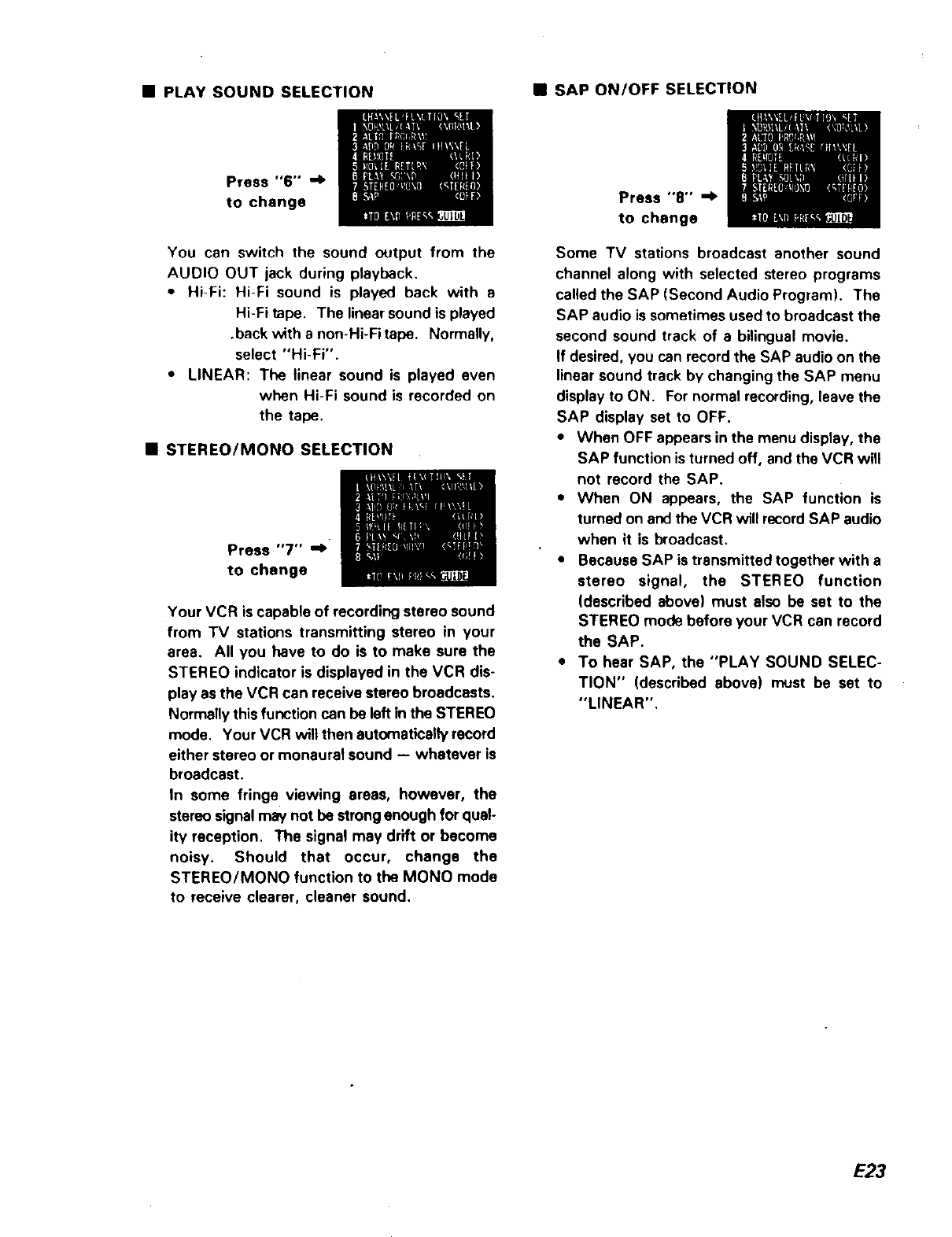
• PLAY SOUND SELECTION •SAP ON/OFF SELECTION
Press "6'" "_
to change
You can switch the sound output from the
AUDIO OUT jack during playback.
•Hi-Fi: Hi-Fi sound is played back with s
Hi-Fi tape. The linearsound is played
.back with a non-Hi-Fi tape. Normally,
select "Hi-Fi".
•LINEAR: The linear sound is played even
when Hi-Fi sound is recorded on
the tape.
•STEREO/MONa SELECTION
Press "7" "_
to change
Your VCR is capable of recording stereo sound
from "IV stations transmitting stereo in your
area. All you have to do is to make sure the
STEREO indicator is displayed in the VCR dis-
play as the VCR can receive stereo broadcasts.
Normally this function can be left in the STEREO
mode. Your VCR wilt then automatically record
either stereo or monaural sound -- whatever is
broadcast.
In some fringe viewing areas, however, the
stereo signal may not be strongenough for qual-
ity reception. The signal may drift or become
noisy. Should that occur, change the
STEREO/MONa function to the MONa mode
to receive clearer, cleaner sound,
Press "8" "_
to change
Some TV stations broadcast another sound
channel along with selected stereo programs
called the SAP (Second Audio Program). The
SAP audio is sometimes used to broadcast the
second sound track of a bilingual movie.
If desired, you can record the SAP audio on the
linear sound track by changing the SAP menu
display to ON. For normal recording, leave the
SAP display set to OFF.
•When OFF appears in the menu display, the
SAP function is turned off, and the VCR will
not record the SAP.
• When ON appears, the SAP function is
turned on and the VCR will record SAP audio
when it is broadcast.
•Because SAP is transmitted together with a
stereo signal, the STEREO function
(described above) must also be set to the
STEREO mode before your VCR can record
the SAP.
•To hear SAP, the "PLAY SOUND SELEC-
TION" (described above) must be set to
"LINEAR".
E23
CASSE'R'E TAPES RECORDING TV PROGRAMS
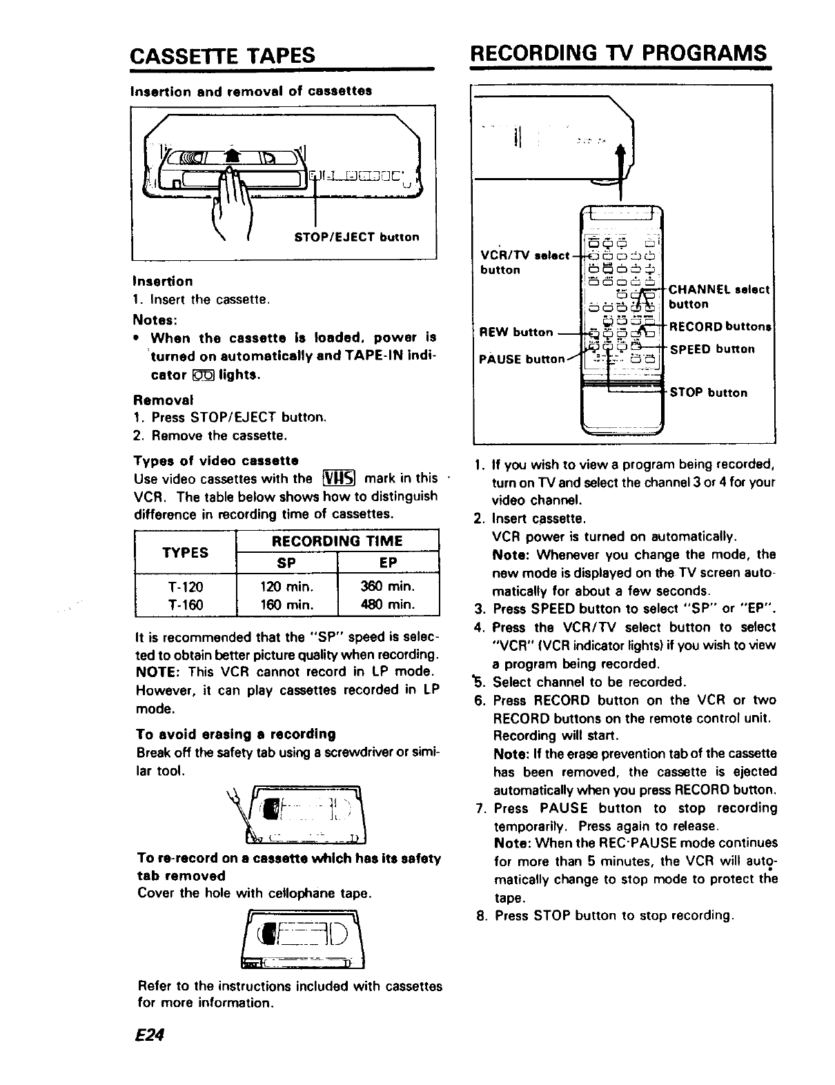
Insertion and removal of cassettes
sL o,--on
Insertion
1. Insert the cassette,
Notes:
• When the cassette is loaded, power is
turned on automatically end TAPE-IN indi-
cator _lights.
Removal
1. Press STOP/EJECT button,
2, Remove the cassette.
Types of video cassette
Use video cassettes with the _mark in this '
VCR, The table below shows how to distinguish
difference in recording time of cassettes,
TYPES
T-120
T-160
RECORDING TIME
SP EP
120 rain. 360 min.
160 min. 480 rain.
It is recommended that the "SP" speed is selec-
ted to obtain better picture quality when recording,
NOTE: This VCR cannot record in LP mode.
However, it can play cassettes recorded in LP
mode.
To avoid erasing arecording
Break off the safety tab usinga screwdriveror simi-
lar tool.
To re-record on e cassette whlch has its safety
tab removed
Cover the hole with cellophane tape.
Refer to the instructions included with cassettes
for more information.
VCR/I"V select-
button
REW button --
PAUSE button I
_. -CHANNEL select
_:_--_:____'_ button
,_ _:__:_ .. *RECORD buttons
._ -sP EObu.o.
-STOP button
1. If you wish to view a program being recorded,
turn on "IV and select the channel 3 or 4 for your
video channel.
2. Insert cassette.
VCR power is turned on automatically.
Note: Whenever you change the mode, the
new mode is displayed on the TV screen auto-
matically for about a few seconds.
3. Press SPEED button to select "SP'" or "'EP".
4. Press the VCR/TV select button to select
"VCR" {VCR indicator lights)ifyou wish to view
aprogram being recorded.
"5. Select channel to be recorded.
6. Press RECORD button on the VCR or two
RECORD buttons on the remote control unit.
Recording will start.
Note: If the erase prevention tab of the cassette
has been removed, the cassette is ejected
automatically when you press RECORD button.
7. Press PAUSE button to stop recording
temporarily. Press again to release.
Note: When the REC'PAUSE mode continues
for more than 5 minutes, the VCR will auto-
matically change to stop mode to protect the
tape.
8. Press STOP button to stop recording.
E24
To record one program while viewing another
You can record one program while viewing another
by setting the VCR for recording, then setting the
VCR/TV select button to "TV", end selecting the
desired channel on your TV.
To change the channel to be recorded while
in record mode
During recording, the channel lock function oper-
ates and channel cannot be changed if the CHAN-
NEL select button is pressed.
If you wish to change channel, proceed as follows.
1. Press the PAUSE button.
2. Change channel desired.
3. Pressthe PAUSE button to releaserecord pause
mode.
Recording broadcast stereo T'V
The basic procedurefor recording broadcast stereo
TV is tbe same as it is for normal off-the-air
recording.
Before you start recording, be sure that "STEREO"
is selected following "STEREO/MONO SELEC-
TION" on page 23. The STEREO indicator will
come on if the station is broadcasting in stereo.
Press the RECORD button to start recording.
Recording Second Audio Program {SAP)
Some stations transmit the Second Audio Pro-
gram. To record the Second Audio Program, be
sure that "ON" is selected following "SAP
ON/OFF SELECTION" on page 23. When the
station broadcasts an SAP, the SAP indicator will
turn on. Press the RECORD button to start
recording.
Your VCR will record the SAP instead of the nor-
mal audio on the linear track. The normal audio
will still be recorded on the Hi-Fi track.
Note: To play back SAP, the "PLAY SOUND
SELECTION" on page 23 must be set to
"LINEAR".
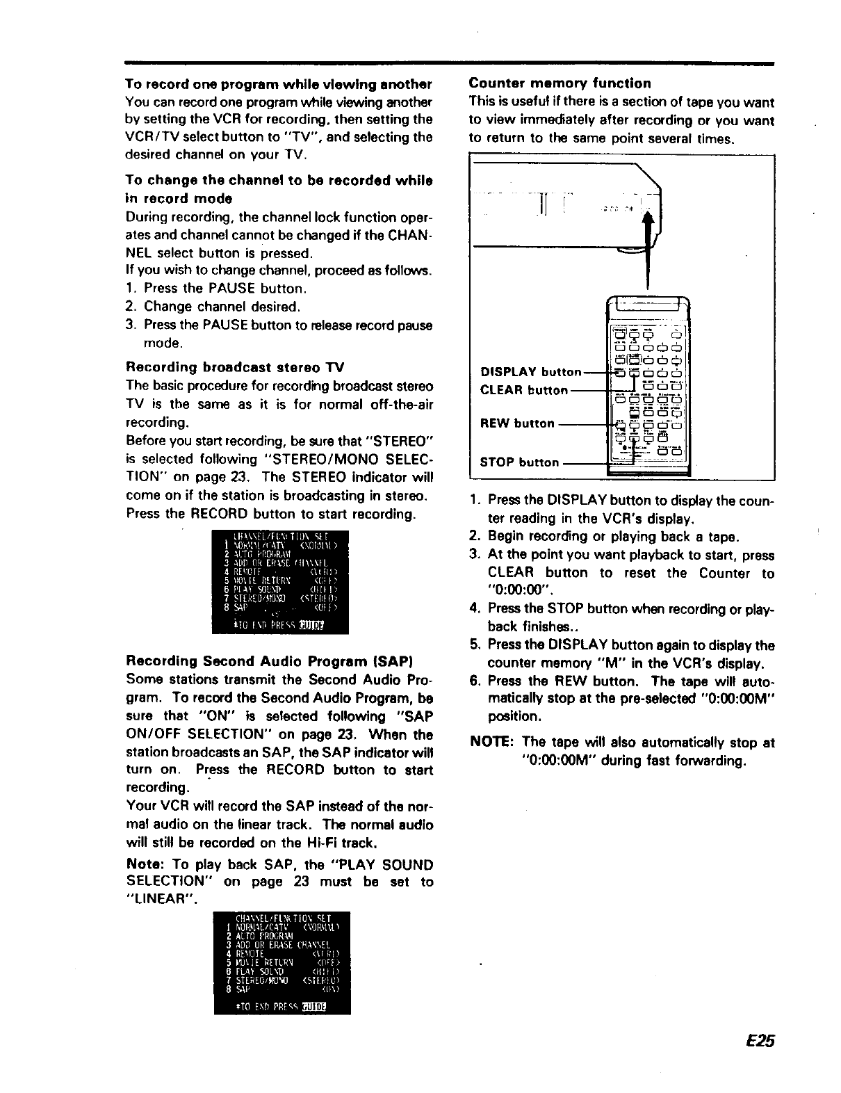
Counter memory function
This is useful if there is a section of tape you want
to view immediately after recording or you want
to return to the same point several times.
.... iT
DISPLAY button--
CLEAR button i
REW button --
STOP button I
1. Pressthe DISPLAY button to display the coun-
ter reading in the VCR's display.
2. Begin recording or playing back a tape.
3. At the point you want playback to start, press
CLEAR button to reset the Counter to
"O:00:00".
4. Pressthe STOP button when recording or play-
back finishes..
5. Press the DISPLAY button again to display the
counter memory "M" in the VCR'a display.
6. Press the REW button. The tape will auto-
matically stop at the pre-sslected "0:00:00M"
position.
NOTE: The tape will also automatically stop at
"0:00:00M" during fast forwarding.
E25
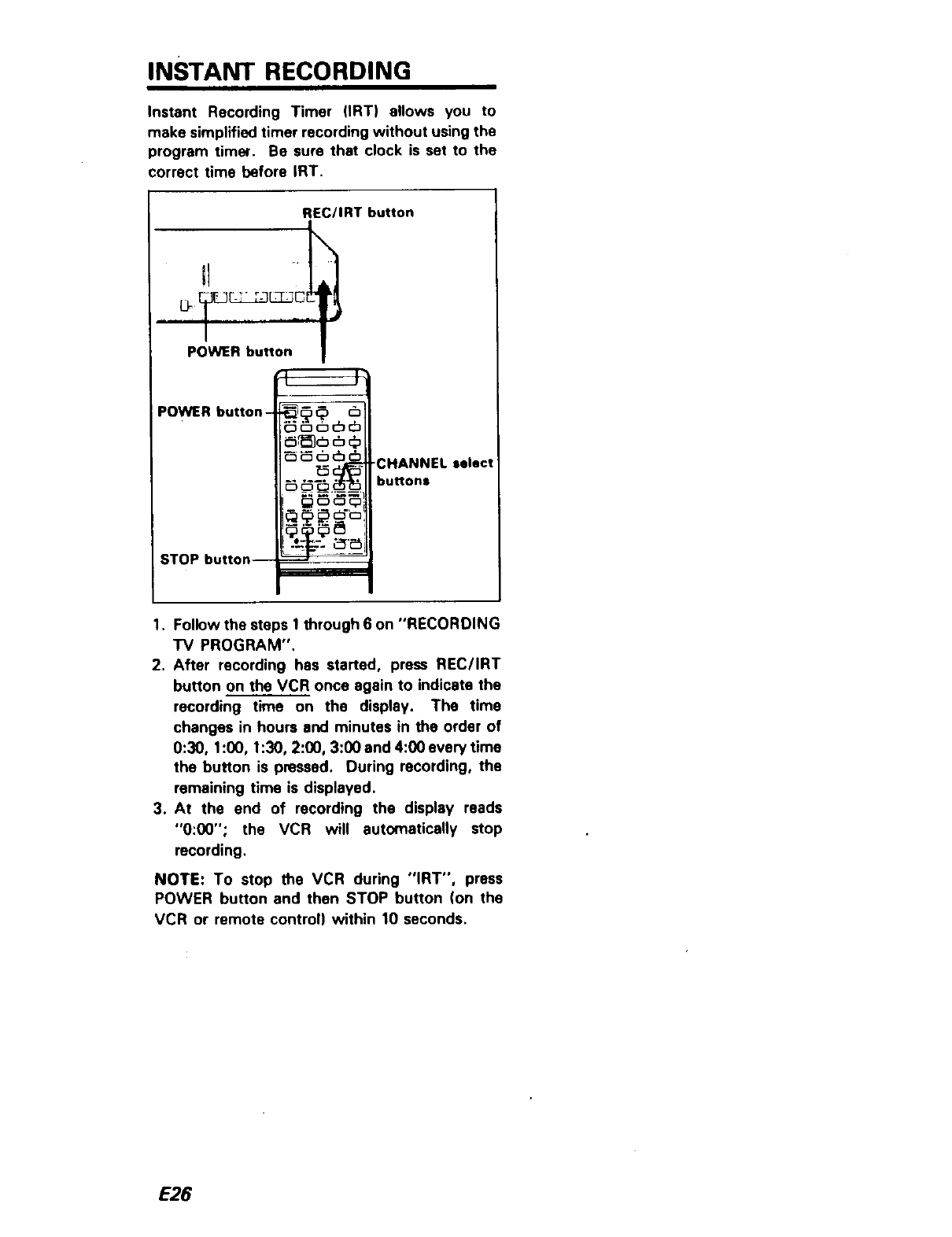
INSTANT RECORDING
Instant Recording Timer (IRT) allows you to
make simplified timer recording without using the
program timer. Be sure that clock is set to the
correct time before IRT.
REC/IRT button
LF_l]EJ_L=Ljc[
I
POWER button
POWER button-
STOP button--
_D Ql_t_
5 _-_ _ -CHANNEL select
....... buttons
i_
1. Followthe steps 1through 6 on "RECORDING
TV PROGRAM".
2. After recording has started, press REC/IRT
button on the VCR once again to indicate the
recording time on the display. The time
changes in hours and minutes in the order of
0:30, 1:00, 1:30, 2:00, 3:00 and 4:00 every time
the button is pressed. During recording, the
remaining time is displayed.
3. At the end of recording the display reads
"0:00"; the VCR will automatically stop
recording.
NOTE: To stop the VCR during "IRT", press
POWER button and then STOP button (on the
VCR or remote control) within 10 seconds.
E26
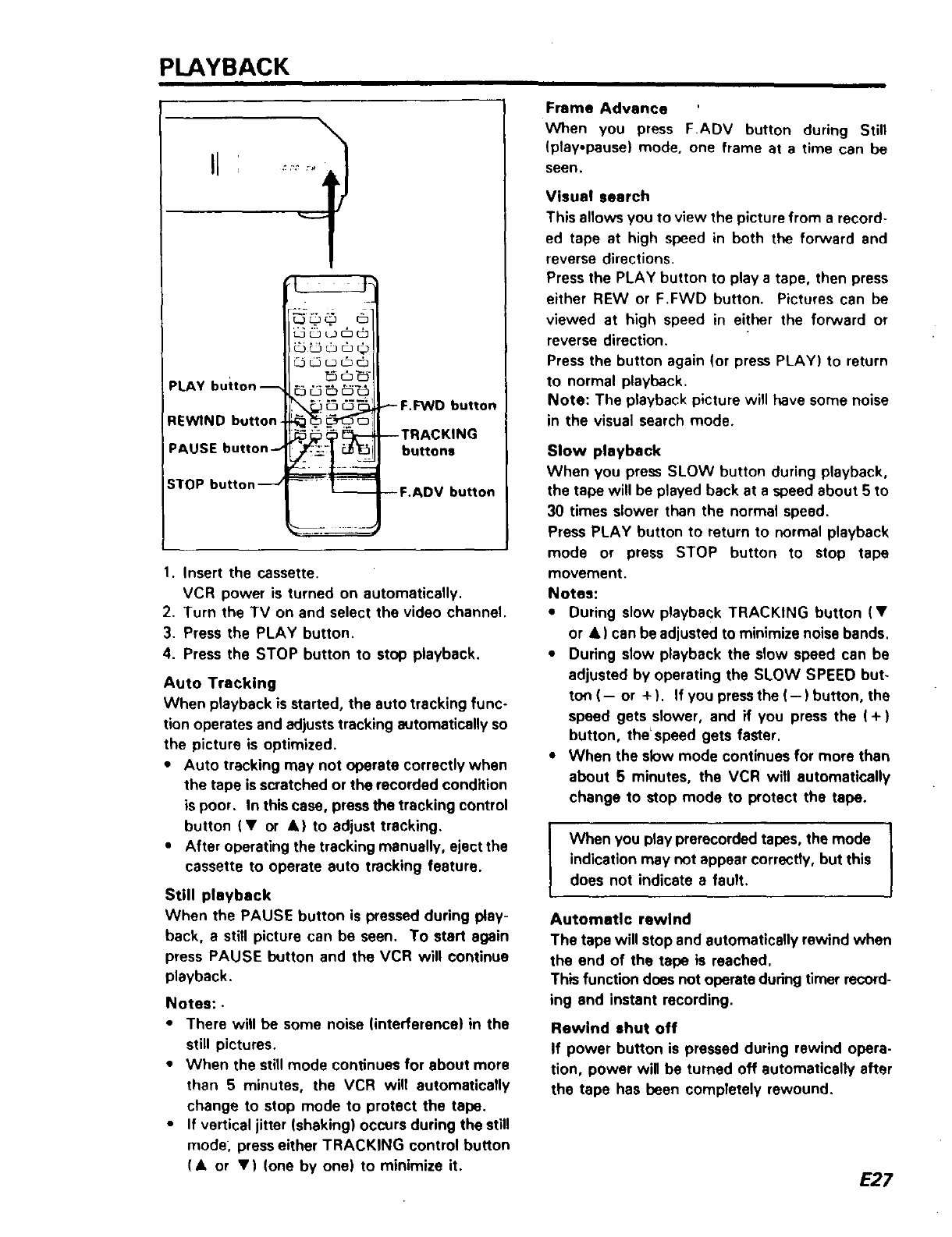
PLAYBACK i
PLAY button-- _°_
REWIND button _,_
PAUSE button_ _
STOP button _J
_F.F_NO button
--TRACKING
buttons
--F.ADV button
1. Insert the cassette.
VCR power is turned on automatically.
2. Turn the TV on and select the video channel.
3. Press the PLAY button.
4. Press the STOP button to stop playback.
Auto Tracking
When playback is started, the auto tracking func-
tion operates and adjusts tracking automatically so
the picture is optimized.
•Auto tracking may not operate correctly when
the tape is scratched or the recorded condition
is poor. In this case, press the tracking control
button (V or k)to adjust tracking.
•After operating the tracking manually, eject the
cassette to operate auto tracking feature.
Still playback
When the PAUSE button is pressed during play-
back, a still picture can be seen. To start again
press PAUSE I_Jtton and the VCR will continue
playback.
Notes: •
•There will be some noise (interference) in the
still pictures.
•When the still mode continues for about more
than 5 minutes, the VCR will automatically
change to stop mode to protect the tape.
•If vertical jitter (shaking) occurs during the still
mode, press either TRACKING control button
(A or V) (one by one) to minimize it.
Frame Advance
VVhen you press F.ADV button during Still
(play.pause) mode, one frame at a time can be
seen.
Visual search
This allows you to view the picture from a record*
ed tape at high speed in both the forward and
reverse directions.
Press the PLAY button to play a tape, then press
either REW or F.FWD button. Pictures can be
viewed at high speed in either the forward or
reverse direction.
Press the button again (or press PLAY) to return
to normal playback.
Note: The playback picture will have some noise
in the visual search mode.
Slow playback
When you press SLOW button during playback,
the tape will be played back at a speed about 5 to
30 times slower than the normal speed,
Press PLAY button to return to normal playback
mode or press STOP button to stop tape
movement.
Notes:
•During slow playback TRACKING button (•
or •) can be adjusted to minimize noise bands,
•During slow playback the slow speed can be
adjusted by operating the SLOW SPEED but-
ton (-- or + ). If you pressthe (-) button, the
speed gets slower, and if you press the ( + )
button, the*speed gets faster.
•When the slow mode continues for more than
about 5 minutes, the VCR will automatically
change to stop mode to protect the tape.
When you play prerecorded tapes, the mode
indication may not appear correctly, but this
does not indicate a fault, I
Automatic rewind
The tape will stop and automatically rewind when
the end of the tape is reached.
This function does not operate dudng timer record-
ing and instant recording.
Rewind shut off
If power button is pressed during rewind opera-
tion, power will be turned off automatically after
the tape has been completely rewound.
E27
Linear Time Counter
The counter on the TV screen or in the VCR
display shows length of tape run in hours,
minutes and seconds.
Load a cassette into the VCR and perform record-
ing or playback; the counter indicates the elapsed
FI • _3 FI •--
Hour Minute
Notes:
• The linear time counter does not operate when
nothing is recorded on the tape.
•Counter changes to 0:00:00 when the cassette
is ejected.
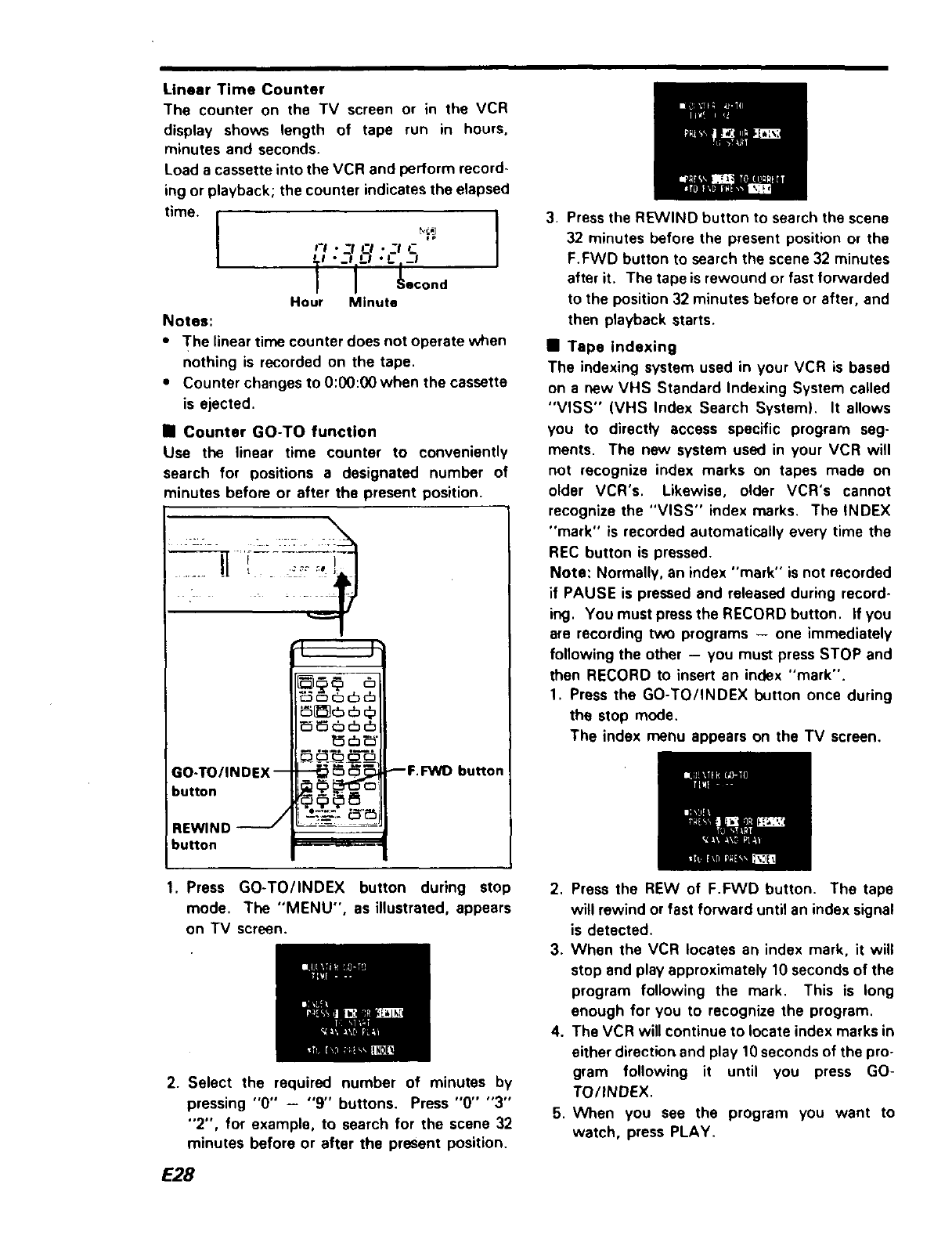
ul Counter GO-TO function
Use the linear time counter to conveniently
search for positions a designated number of
minutes before or after the present position.
m
_ _ _ _,-_,
GO-TO/INDEX-- "" --
button _
REW1ND
button =========_-
_F.FWID button
3. Pressthe REWIND button to search the scene
32 minutes before the present position or the
F.FWD button to search the scene 32 minutes
after it. The tape is rewound or fast forwarded
to the position 32 minutes before or after, and
then playback starts.
•Tape indexing
The indexing system used in your VCR is based
on a new VHS Standard Indexing System called
"VISS" (VHS Index Search System). It allows
you to directly access specific program seg-
ments. The new system used in your VCR will
not recognize index marks on tapes made on
older VCR's. Likewise, older VCR's cannot
recognize the "VISS" index marks. The INDEX
"mark" is recorded automatically every time the
REC button is pressed.
Note: Normally, an index "mark" is not recorded
if PAUSE is pressed and released during record-
ing. You must press the RECORD button. If you
are recording two programs -- one immediately
following the other - you must press STOP and
then RECORD to insert an index "mark".
1. Press the GO-TO/INDEX button once during
the stop mode.
The index menu appears on the TV screen,
1. Press GO-TO/INDEX button during stop
mode. The "MENU", as illustrated, appears
on TV screen,
2. Select the required number of minutes by
pressing "0" -"9" buttons. Press "0" "3"
"2", for example, to search for the scene 32
minutes before or after the present position.
E28
2. Press the REW of F.FWD button. The tape
will rewind or fast forward until an index signal
is detected.
3. When the VCR locates an index mark, it will
stop and play approximately 10 seconds of the
program following the mark. This is long
enough for you to recognize the program.
4. The VCR will continue to locate index marks in
either directior_and play 10seconds of the pro-
gram following it until you press GO-
TO/INDEX.
5. When you see the program you want to
watch, press PLAY.
TIMER RECORDING
The programmable electronic clock/timer permits the unattended recording of up to 8 preselected pro-
rams, including one program on the same day of each week or one program at the same time every day.
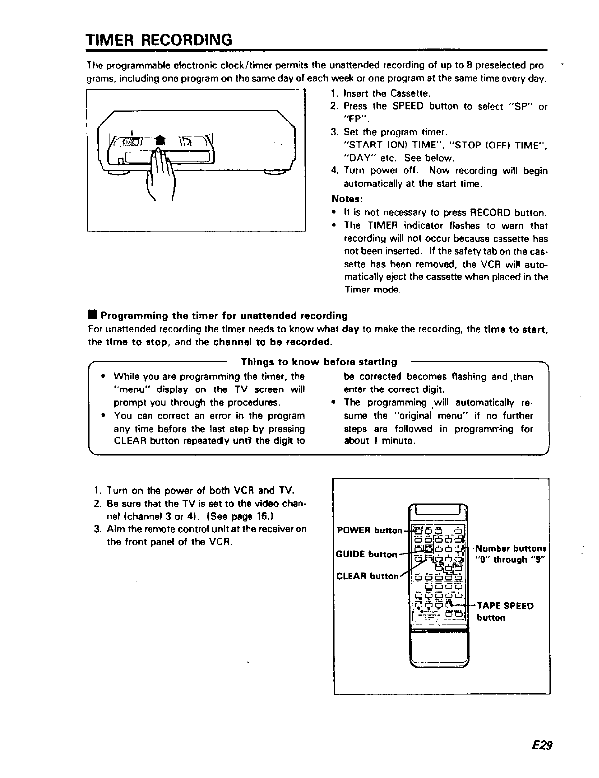
1. Insert the Cassette.
2. Press the SPEED button to select "SP" or
"EP'.
3. Set the program timer.
"START (ON) TIME", "STOP (OFF) TIME",
"DAY" etc. See below.
4. Turn power off. Now recording will begin
automatically at the start time.
Notes:
•It is not necessary to press RECORD button.
• The TIMER indicator flashes to warn that
recording will not occur because cassette has
not been inserted. If the safety tab on the cas-
sette has been removed, the VCR will auto-
matically eject the cassette when placed in the
Timer mode.
•Programming the timer for unattended recording
For unattended recording the timer needs to know what day to make the recording, the time to start,
the time to stop, and the channel to be recorded.
Things to know before starting
•While you are programming the timer, the
"menu" display on the TV screen will
prompt you through the procedures.
• You can correct an error in the program
any time before the last step by pressing
CLEAR button repeatedly until the digit to
be corrected becomes flashing and .then
enter the correct digit.
•The programming ,will automatically re-
sume the "original menu" if no further
steps are followed in programming for
about 1 minute.
1. Turn on the power of both VCR and TV.
2. Be sure that the TV is set to the video chan-
nel (channel 3 or 4). (See page 16.)
3. Aim the remote control unit at the receiver on
the front panel of the VCR.
POWER button-
GUIDE button_
CLEAR button /OOO_C
•
-Number buttons
"0" through "9"
-TAPE SPEED
button
E29
TIMER RECORDING (cont)
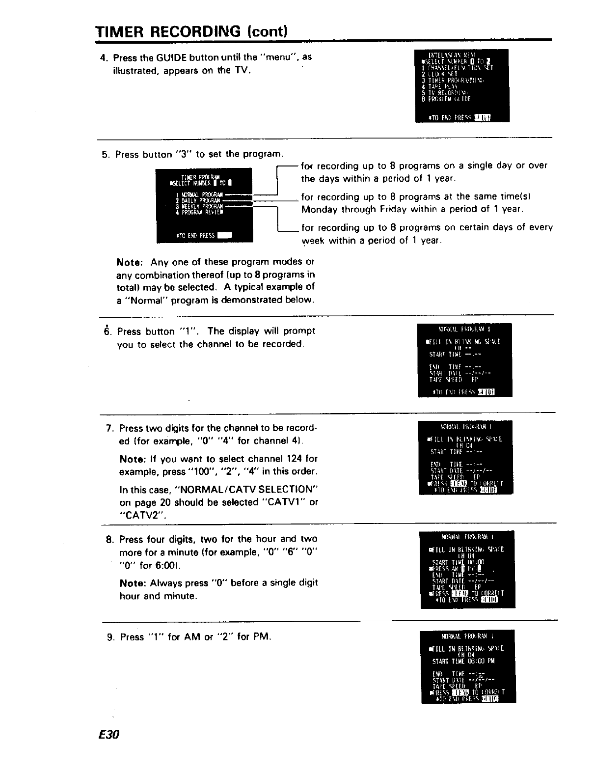
4. Press the GUIDE button until the "menu", as
illustrated, appears on the TV.
5. Press button "3" to set the program.
recording up to 8 programs on a single day or over
the days within a period of I year.
for recording up to 8 programs at the same time(s)
Monday through Friday within a period of 1year.
•for recording up to 8programs on certain days of every
_veek within a period of 1year.
Note: Any one of these program modes or
any combination thereof (up to 8 programs in
total) may be selected. A typical example of
a"Normal" program is demonstrated below.
6. Press button "1". The display will prompt
you to select the channel to be recorded.
7. Press two digits for the channel to be record-
ed (for example, "0" "4" for channel 4).
Note: If you want to select channel 124 for
example, press "100", "2", "4" in this order.
In this case, "NORMAL/CATV SELECTION"
on page 20 should be selected "CATVI'" or
"CATV2".
8. Press four digits, two for the hour and two
more for a minute (for example, "0" "6" "0"
"0" for 6:00).
Note: Always press "0" before a single digit
hour and minute.
9. Press "1" for AM or "2" for PM.
E30
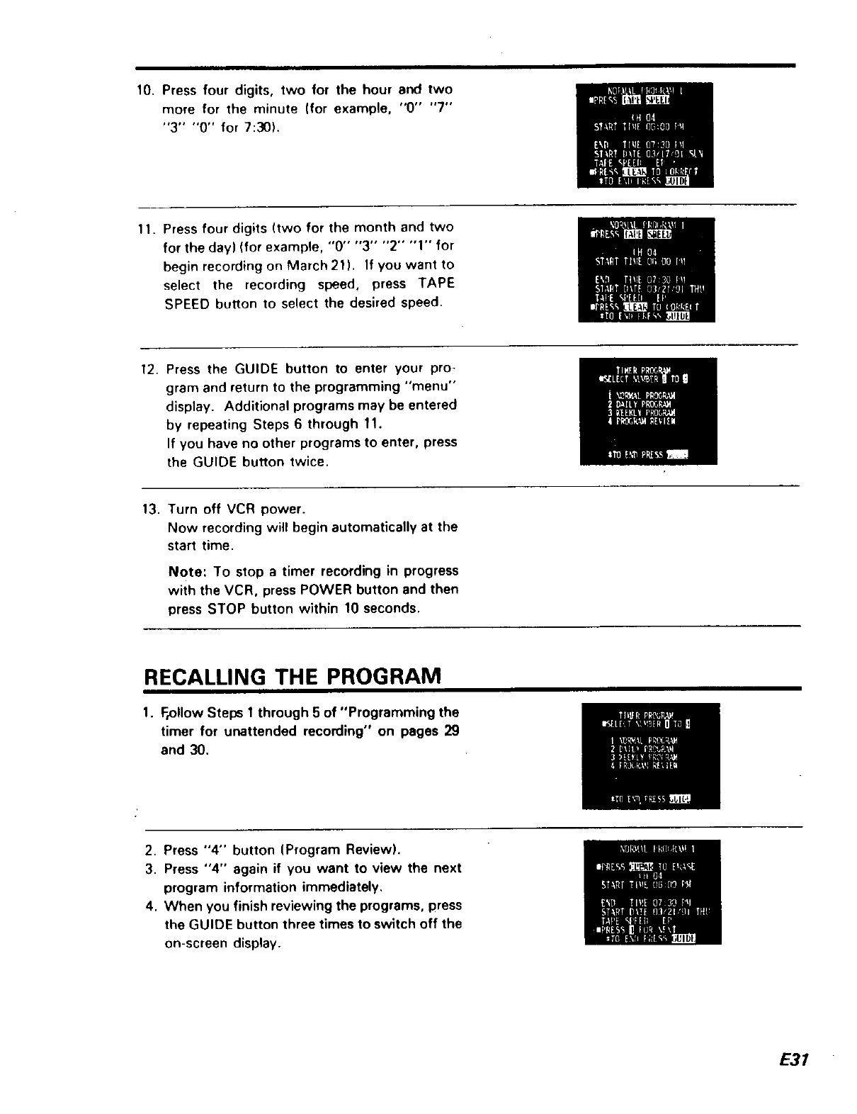
10. Press four digits, two for the hour and two
more for the minute (for example, "0" "7"
"3" "0" for 7:30L
11. Press four digits (two for the month and two
for the day) (for example, "0" "3" "2" "1" for
begin recording on March 21). If you want to
select the recording speed, press TAPE
SPEED button to select the desired speed.
12. Press the GUIDE button to enter your pro-
gram and return to the programming "menu"
display. Additional programs may be entered
by repeating Steps 6 through 11.
If you have no other programs to enter, press
the GUIDE button twice.
13. Turn off VCR power.
Now recording will begin automatically at the
start time.
Note: To stop a timer recording in progress
with the VCR, press POWER button and then
press STOP button within 10 seconds.
RECALLING THE PROGRAM
1. Follow Steps 1through 5 of "Programming the
timer for unattended recording" on pages 29
and 30.
2. Press "4" button (Program Review).
3. Press "4" again if you want to view the next
program information immediately.
4. When you finish reviewing the programs, press
the GUIDE button three times to switch off the
on-screen display.
E31
CLEARING ("ERASING") INFORMATION FROM A PROGRAM
1. Follow Steps 1 through 5 of "Programming
the timer for unattended recording" on pages
29 and 30.
2. Press "4" button (Program Review).
3. Press "4" again if you want to view the next
program information immediately.
4. Press CLEAR button when the program infor-
mation .you want to clear is displayed.
5. Press the GUIDE button three times to switch
off the on-screen display.
Note:
•Normal program is cleared automatically when
the timer recording is finished, but daily and
weekly programs remain in the timer even
after the timer recording is finished.
PROGRAM PRIORITY
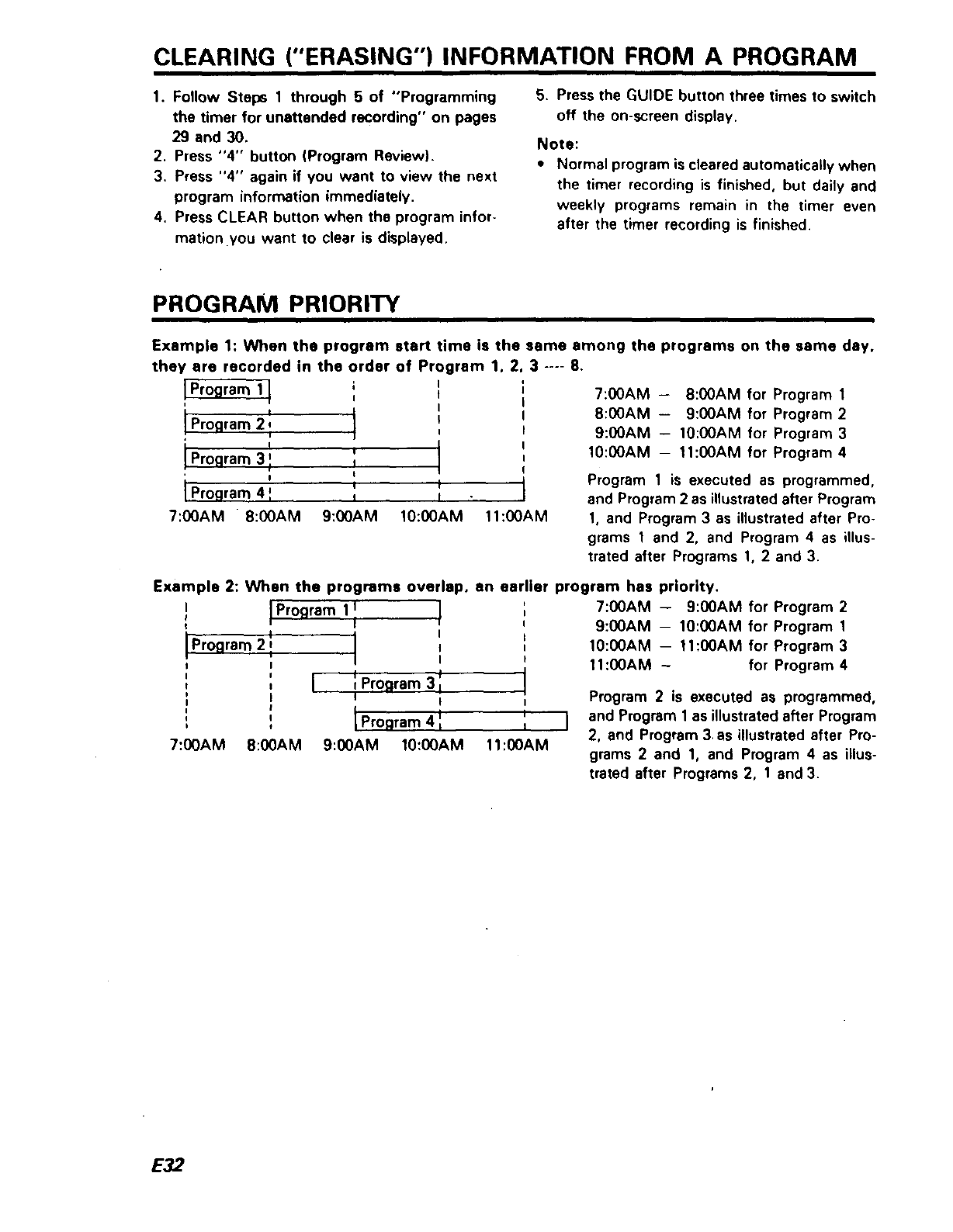
Example 1: When the program start time is the s=
they are recorded in the order of Program 1, 2,
l I
I
IP ' I
rogram 2, I
l I
i°- I
Ii
,ro_ram i
II
IProgram 4 ', t_II
7:00AM " 8:00AM 9:00AM 10:00AM 11:00AM
,me among the programs on the same day.
:.... 8.
7:00AM -8:00AM for Program 1
8:00AM -9:00AM for Program 2
9:00AM - 10:00AM for Program 3
10:00AM -11:00AM for Program 4
Program 1 is executed as programmed,
and Program 2 as illustrated after Program
1, and Program 3 as illustrated after Pro-
grams 1and 2, and Program 4 as illus-
trated after Programs 1, 2 and 3.
Example 2: When the programs overlap, an earlier program has priority.
!Program 1!
I
Program 2 i,
I
I
I
I
I
I
7:00AM 8:00AM
,I
!'
I
I
I i t
Program 3 I
I I
i i
IProgram 4 1 = I
9:00AM 10:00AM 11:00AM
7:00AM -9:00AM for Program 2
9:00AM - 10:00AM for Program 1
10:00AM -- 11:00AM for Program 3
11:00AM - for Program 4
Program 2 is executed as programmed,
and Program 1as illustrated after Program
2, and Program 3 as illustrated after Pro-
grams 2 and 1, and Program 4 as illus-
trated after Programs 2, 1 and 3.
E32
HOW TO OPERATE YOUR TV BY USING THE REMOTE
CONTROL UNIT
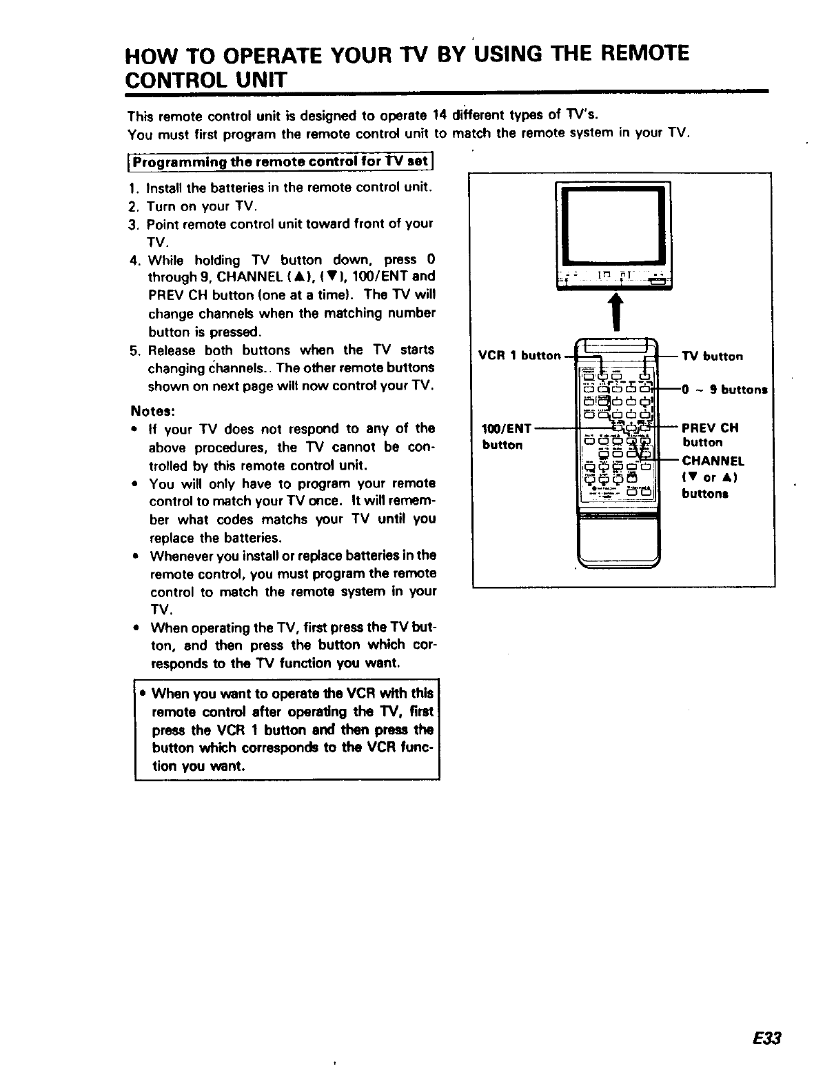
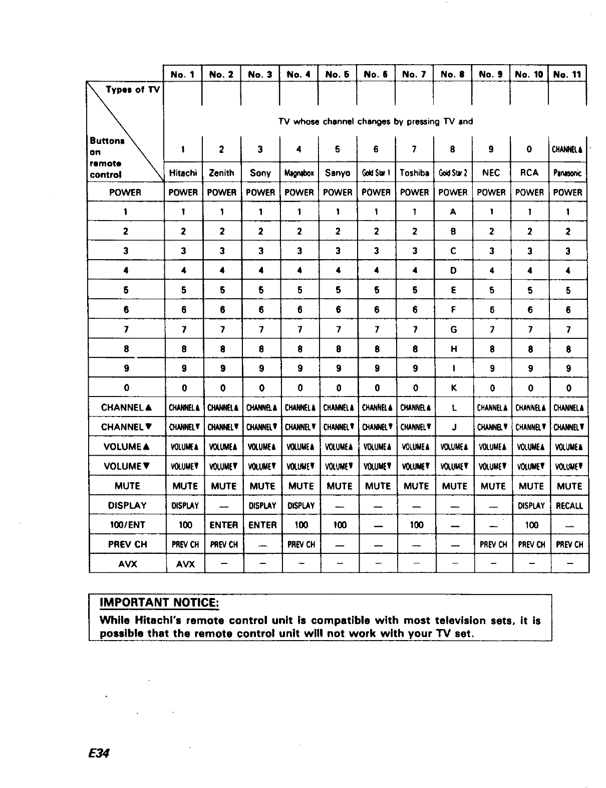
This remote control unit is designed to operate 14 different types of TV's.
You must first program the remote control unit to match the remote system in your TV.
IProgramming the remote control for "IV set I
1. Install the batteries in the remote control unit,
2. Turn on your TV.
3. Point remote control unit toward front of your
TV.
4. While holding TV button down, press 0
through 9, CHANNEL (•), (•), 100lENT and
PREV CH button (one at a time). The TV will
change channels when the matching number
button is pressed.
5. Release both buttons when the TV starts
changing (_hannels. The other remote buttons
shown on next page wilt now control your TV.
Notes:
• If your TV does not respond to any of the
above procedures, the TV cannot be con-
trolled by this remote control unit.
•You will only have to program your remote
control to match your TV once. It will remem-
ber what codes matchs your TV until you
replace the batteries.
•Whenever you install or replace batteries in the
remote control, you must program the remote
control to match the remote system in your
TV.
• When operating the TV, first press the "IV but-
ton, and then press the button which cor-
responds to the TV function you want.
= When you want to operate the VCR with this
remote control after operating the TV, first
press the VCR 1 button end then press the
button which corresponds to the VCR func-
tion you want.
! 1
!
VCR 1 button- ---_ r-
IO0/ENT =. _,._,'
button ._ _. -
-- TV button
--0 ~ 9 buttons
-- PREV CH
button
--CHANNEL
IV or &)
buttons
E33
fTV
remote
POWER
t
2
3
4
5
6
7
8
9
0
CHANNEL&
CHANNELV
VOLUME•
VOLUMEV
MUTE
DISPLAY
1OO/ENT
PREV CH
AVX
No. 1 No. 2 No. 3 No. 4 No. 5 No, 8 No. 7 No, 8 No. 9 No. 10 No. 11
"IV whose channel changes by pressing TV and
I 2 3 4 5 6 7 8 9 0 CHANNEL,
Hitachi Zenith Sony Mzgnab0x Sanyo G0tlSt_I Toshiba G_ S_"2 NEC RCA PINI_O_
POWER POWER POWER POWER POWER POWER POWER POWER POWER POWER POWER
I 1 1 1 11 1 A11I
2222222B222
3333333C333
4444444D444
5555555E555
66 6 6 6 6 6 F 6 6 6
7 7 77 7 7 7 G 7 7 7
8 8 8 8 8 8 8 H 8 8 8
9 9 9 9 9 9 9 I 9 9 9
0 0 0 0 0 0 0 K 0 0 0
CHANNEL&CHANN[L&CHANNB.&CHANNEL&CHANNEL,CHANNELICHANNEL& L CHANNEL&CHANNEL&CHANNEL&
CHANNELVCHANNZLv CHANNELlfCHANNELVCHANNELI CHANNEL!r CHANNELV JCHANNrlf CHANNELVCHANNELI
VOLUMEAVOI.LIME, VOLUME, VOLUME/'JVOLUMEAVOLUME` VOLUME"VOLUME, VOLUME, VOLUME/,VOLUME/,
VOLUMETVOLUMEVVOLUMEVVOLUMEVVOLUMEWVOLUMElfVOLUMElfVOLUMEr VOLUMEVVOLUMEVVOLUMEV
MUTE MUTE MUTE MUTE MUTE MUTE MUTE MUTE MUTE MUTE MUTE
DISPLAY -- OISPLAY DISPLAY ..... DISPLAY RECALL
100 ENTER ENTER 100 100 -- 100 -- -- 100 --
PREVOH PREVCH -- P:REVCH .... PREVCH PREVCH PREVCH
AVX ..........
IMPORTANT NOTICE: I
While Hitachi's remote control unit is compatible with most television sets, it is
possible that the remote control unit will not work with your TV set.
E34
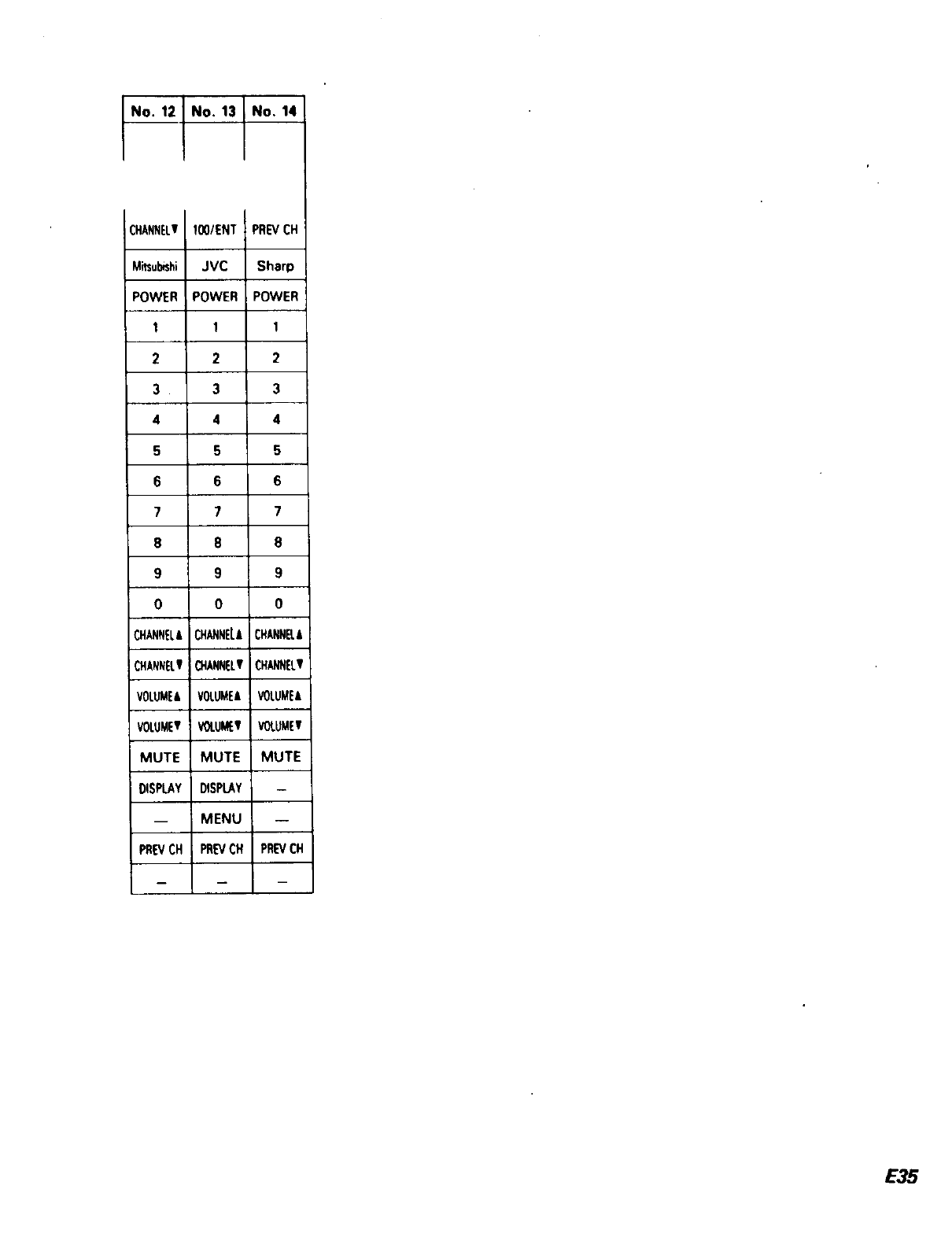
No. 12 No. 13 No. 141
CHANNELTIO0/ENT PREVCH
M_ub_shi JVC Sharp
POWER POWER POWER
111
2 2 2
333
4 4 4
555
666
7 7 7
8 8 8
9 9 9
0 0 0
CHANNEL&CHANNELA CHANNB.A
CHANNELTCHANNELTCHANNELV
VOLUMEAVOLUME&VOLUME&
VOLUMET!VOLU_V VOLUME_
MUTE MUTE MUTE
DISPLAY DISPLAY
-- MENU --
PN_CH PREVCH PREVCH
E35
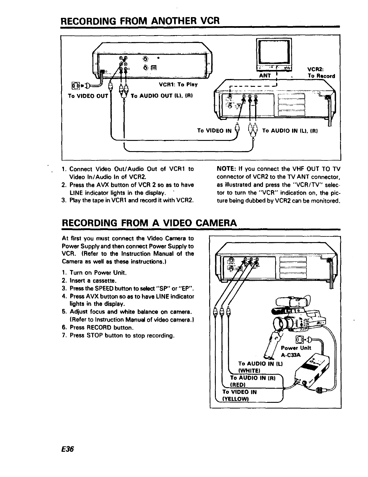
RECORDING FROM ANOTHER VCR
\
T ' EOOU,l ii,o :': ANT I
I
VCR2:
To Record
To VIDEO IN,)_
To AUDIO IN (L). (R)
1. Connect Video Out/Audio Out of VCR1 to
Video In/Audio In of VCR2.
2. Press the AVX button of VCR 2 so as to have
LINE indicator lights in the display.
3. Play the tape inVCR1 and record it with VCR2.
NOTE: If you connect the VHF OUT TO TV
connector of VCR2 to the TV ANT connector,
as illustrated and press the "VCR/TV" selec-
tor to turn the "VCR" indication on. the pic-
ture being dubbed by VCR2 can be monitored.
RECORDING FROM A VIDEO CAMERA
At first you must connect the Video Camera to
Power Supply and then connect Power Supply to
VCR. (Refer to the Instruction Manual of the
Camera as well as these instructions.)
1. Turn on Power Unit.
2. Insert a cassette.
3. Pressthe SPEED button to select "SP" or "EP".
4. Press AVX button so as to have LINE indicator
lights in the display.
5. Adjust focus and white balance on camera.
(Refer to Instruction Manual of video camera.)
6. Press RECORD button.
7. Press STOP button to stop recording.
E36
(YELLOWI
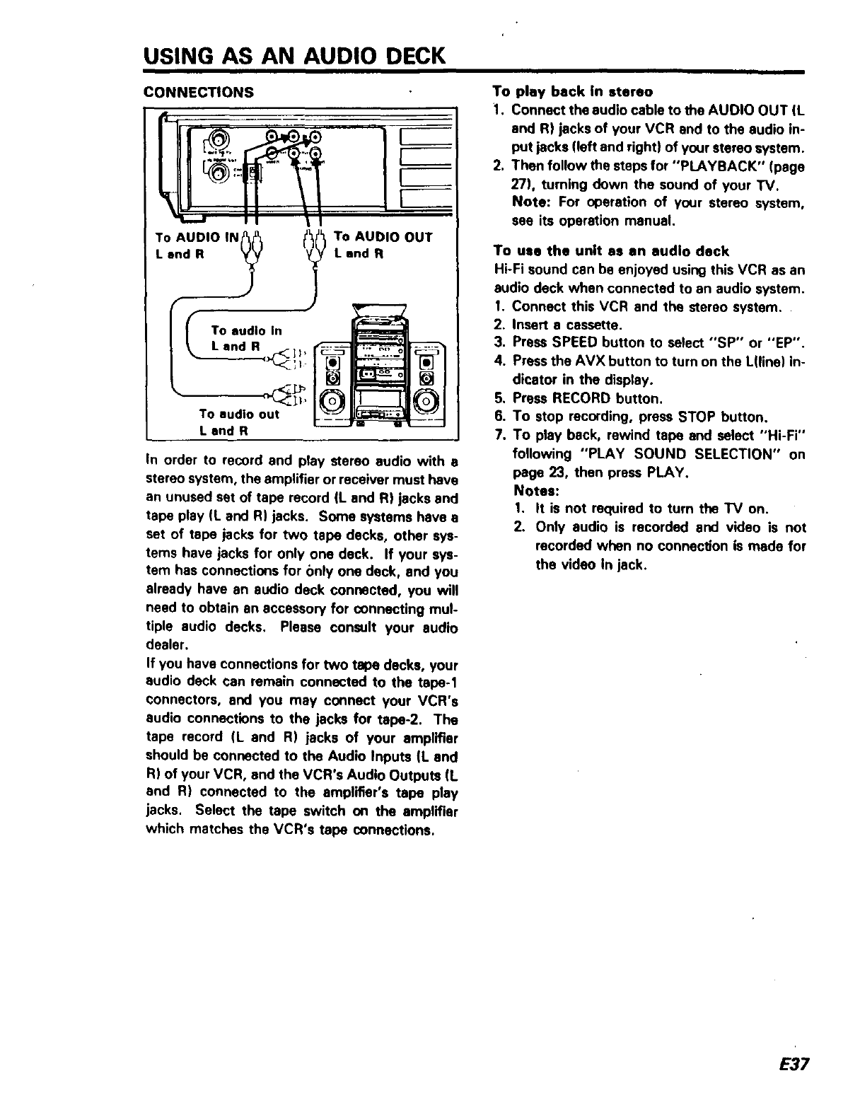
USING AS AN AUDIO DECK
CONNECTIONS
To AUDIO IN? f? TO AUDIO OUT
I. and R Land R
To audio In
Land R,-<-]I,
To audio out
Land R
[]
In order to record and play stereo audio with s
stereo system, the amplifier or receiver must have
an unused set of tape record (L and R) jacks and
tape play (L and R) jacks. Some systems have a
set of tape jacks for two tape decks, other sys-
tems have jacks for only one deck. If your sys-
tem has connections for only one deck, and you
already have an audio deck connected, you will
need to obtain an accessory for connecting mul-
tiple audio decks. Please consult your audio
dealer.
If you have connections for two tape decks, your
audio deck can remain connected to the tape-1
connectors, and you may connect your VCR's
audio connections to the jacks for tape-2. The
tape record (L and R) jacks of your amplifier
should be connected to the Audio Inputs (L and
R) of your VCR, and the VCR's Audio Outputs (L
and R) connected to the amplifier's tape play
jacks, Select the tape switch on the amplifier
which matches the VCR's tape connections.
To play back In stereo
1. Connect the audio cable to the AUDIO OUT (L
and R) jacks of your VCR and to the audio in-
put jacks (left and right) of your stereo system.
2. Then follow the steps for "PLAYBACK" (page
27), turning down the sound of your TV.
Note: For operation of your stereo system,
see its operation manual.
To use the unit as an audio deck
Hi-Fi sound can be enjoyed using this VCR as an
audio deck when connected to an audio system.
I. Connect this VCR and the stereo system.
2. Insert a cassette.
3. Press SPEED button to select "SP" or "EP".
4.
.
6.
7.
Press the AVX button to turn on the L(line) in-
dicator in the display.
Press RECORD button.
To stop recording, press STOP button.
To play back, rewind tape and select "Hi-Fi"
following "PLAY SOUND SELECTION" on
page 23, then press PLAY.
Notes:
1. It is not required to turn the TV on.
2. Only audio is recorded and video is not
recorded when no connec#on is made for
the video In jack.
E37
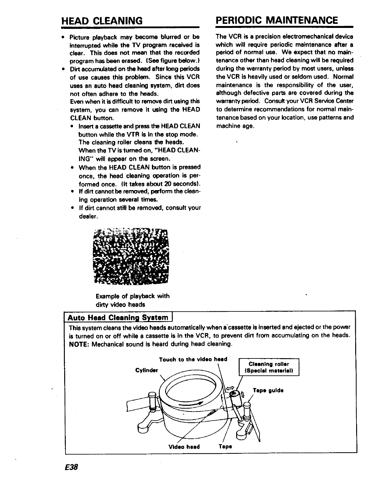
HEAD CLEANING PERIODIC MAINTENANCE
• Picture playback may become blurred or be
interrupted while the TV program received is
clear. This does not mean that the recorded
program has been erased. (See figure below.}
• Dirt accumulated on the head after long periods
of use causes this problem. Since this VCR
uses an auto head cleaning system, dirt does
not often adhere to the heads.
Even when it isdifficult to remove dirt using this
system, you can remove it using the HEAD
CLEAN button.
•Insert a cassette and pressthe HEAD CLEAN
button while the VTR is in the stop mode.
The cleaning roller cleans the heads.
When the TV is turned on, "HEAD CLEAN-
ING" will appear on the screen.
•When the HEAD CLEAN button is pressed
once, the head cleaning operation is per-
formed once. lit takes about 20 seconds).
•If dirt cannot be removed, perform the clean-
ing operation several times.
•If dirt cannot still be removed, consult your
dealer.
The VCR is a precision electromechanical device
which will require periodic maintenance after a
period of normal use. We expect that no main-
tenance other than head cleaning will be required
during the warranty period by most users, unless
the VCR is heavily used or seldom used. Normal
maintenance is the responsibility of the user,
although defective parts are covered during the
warranty period. Consult your VCR Sen/ice Center
to determine recommendations for normal main-
tenance based on your location, use patterns and
machine age.
W
Example of playback with
dirty video heads
Auto Head Cleaning System I
This system cleans the video heads automatically when a'csssette is inserted and ejected or the power
is turned on or off while a cassette is in the VCR, to prevent dirt from accumulating on the heads,
NOTE: Mechanical sound is heard during head cleaning.
Touch to the video heed
Cylinder Cleaning roller ]
|Special material|
Tspe guide
Video heed Tape
E38
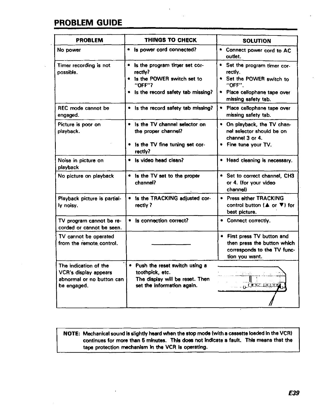
PROBLEM GUIDE
PROBLEM
No power
Timer recording is not
)ossible.
RECmode cannot be
engaged.
Picture is poor on
playback.
Noise in picture on
playback
No picture on playback
Playback picture is partial-
ly noisy.
IV program cannot be re-
corded or cannot be seen.
TV cannot be operated
from the remote, control.
The indication of the
VCR's display appeam
abnormal or no button can
be engaged,
THINGS TO CHECK
• Is power cord connected?
•Is the program tlrQer set cor-
rectly?
• Is the POWER switch set to
"OFF"?
•Is the record safety tab missing?
•Is the record safety tab missing?
•Is the TV channel selector on
the proper channel?
• Is the TV fine tuning set cor-
rectly?
•Is video head clean?
•Is the TV set to the proper
channel?
i0Is the TRACKING adjusted cor-
rectly ?
•Is connection correct?
"! •Push the reset switch using s
toothpick, etc.
The display will be reset. Then
set the information again.
SOLUTION
•Connect power cord to AC
outlet.
•Set the program timer cor-
rectly.
QSet the POWER switch to
"OFF",
•Place cellophane tape over
missing safety tab.
tPlace cellophane tape over
missing safety tab.
•On playback, the TV chan-
nel selector should be on
channel 3 or 4.
•Fine tune your TV.
•Head cleaning is necessary.
•Set to correct channel, CH3
or 4. (for your video
channel}
•Press either TRACKING
control button (• or •) for
best picture.
•Connect correctly.
Fimt press TV button and
then press the button which
corresponds to the "IV func-
tion you went.
..... _¥[ ..... • -"i--'__
=in mn nl /
NOTE: Mechanical sound Is slightly heard when the stop mode (with a cassette loaded In the VCR)
continues for more than 5 minutes. This does not Indicate a fault, This means that the
tape protection mechanism in the VCR Is operating.
E39
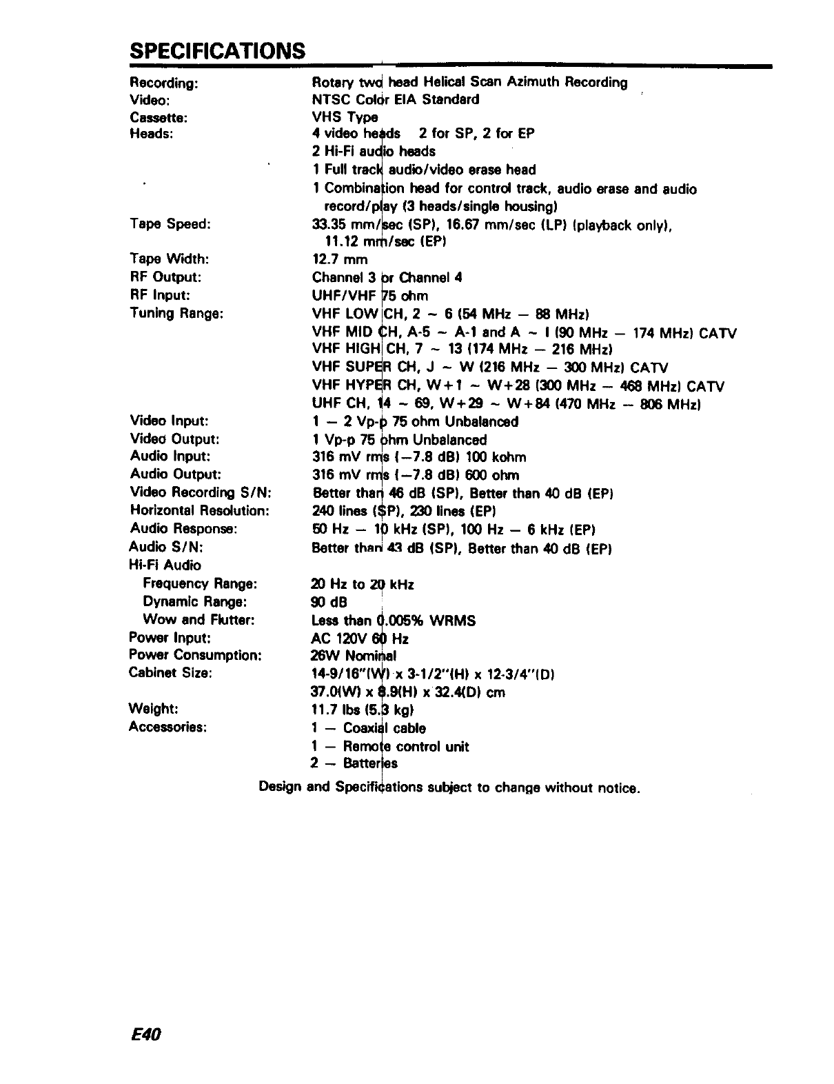
SPECIFICATIONS i
Recording:
Video:
Cassette:
Heads:
Tape Speed:
Tape Width:
RF Output:
RF Input:
Tuning Range:
Video Input:
Video Output:
Audio Input:
Audio Output:
Video Recording SIN:
Horizontal Resolution:
Audio Response:
Audio S/N:
Hi-Fi Audio
Frequency Range:
Dynamic Range:
Wow end Flutter:
Power Input:
Power Consumption:
Cabinet Size:
Weight:
Accessories:
Design
Rotary two heed Helical Scan Azimuth Recording
NTSC ColOr EIA Standard
VHS Type
4 video hepds 2 for SP, 2 for EP
2 Hi-Fi audio heads
1 Full tracl_ audio/video erase head
1 Combination head for control track, audio erase and audio
record/p(ay (3 heads/single housing)
33.35 mm/_sec (SP), 16.67 mm/sec (LP) (playback only),
11.12 ram/sac (EP)
12.7 mm
Channel 3 pr Channel 4
UHF/VHF _5 ohm
VHF LOW!CH, 2~6 (54 MHz - 88 MHz)
VHF MID CH, A-5 - A-1 and A -I (90 MHz -- 174 MHz) CATV
VHF HIGHi CH, 7 - 13 (174 MHz - 216 MHz)
VHF SUPER CH, J ~ W (216 MHz - 300 MHz) CATV
VHF HYPER CH, W+I - W+28 (300 MHz - 468 MHz) CATV
UHF CH, 14 - 69, W+29 - W+84 (470 MHz -- 806 MHz)
1-- 2 Vp-p 75 ohm Unbalanced
1 Vp-p 75 phm Unbalanced
316 mV rms (-7.8 dB) 100 kohm
318 mV rn_s (--7.8 dB) 600 ohm
Better than46 dB (SP), Better than 40 dB (EP)
/
240 lines ($P), 230 lines (EP)
50 Hz -- 10 kHz (SP), 100 Hz -- 6 kHz (EP)
I
Better than 4.3 dB (SP), Better than 40 dB (EP)
20 Hz to 20 kHz
9O dB
Less than (I.005% WRMS
AC 120V 60 Hz
26W Nominal
14-9/16"(W) x 3-1/2"(H| x 12-3/4"(D)
/
37.0(W) x 8.9(H) x 32.4(D) cm
11.7 Iba (6.3 kg)
i
1 -- Coaxial cable
1 Remote control unit
2 -- Better!es
..' .
and SpecifiCat,ons subject to change without notice.
E40
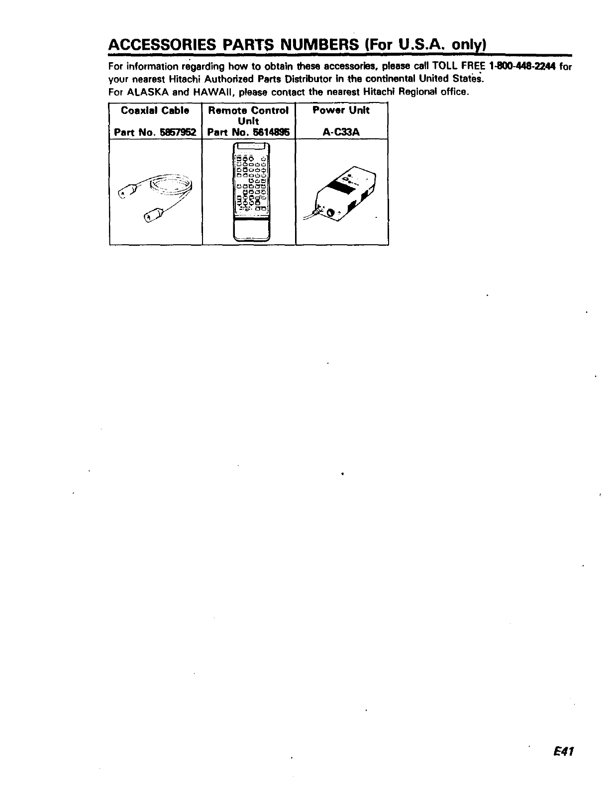
ACCESSORIES PARTS NUMBERS (For U.S.A. only)
For information regarding how to obtain these accessories, please call TOLL FREE 1-800-448-2244 for
your nearest Hitachi Authorized Parts Distributor in the continental United States.
For ALASKA and HAWAII, please contact the nearest Hitachi Regional office.
Coaxial Cable Remote Control Power Unit
Unit
Part No. 5857952 Part No. 6614896 A-C33A
1ZZ_ I
f_dJ_
E41
HITACHI
To locale an authorized
HITACHI service facllily
in the conl_nental U S A
DIAL TOLL FREE
7 days a week, 24 hours a day
You must statf_ zip code when calling 1-800-448-2244
Hitachi Home Electronics (America), Inc.
Hdacl_hasmadeevelyeflo_loas$_*eyoQhaiJrsoflroQIbleh_al_hOmy_u_ Ho*ever $ha*J_yO,Jrequ_resent,ce anefwOrkOIHi1aCh, Aurr_o.zeOServ_e
F aCml_-,shas been er_at_lshe0 in _ 50 slates at,0 Pue,'lO R_O Each lacC._ywdl p,ovde yo_ wl_ ¢o_venent and eRpe0,ent assrstance Our serv_e Horhrq_ 00el atOr _l_ _t_l
you tOfbe HdaC_ AU11_Or_Ze(IServiCe Faokly _earesl you JuSl _esenl J_oof of purChZSea,_ Or belrvery recess 1o_H_lacr. AuthOf_ZeOSe_<e FaOhl_ a_ serv,ce *,t_ be
rer_ered _ acco_0a_e w_h the lerms o_the _mded wa_anly as slaled o_ you_wartanly card O_0perat_g gu<_
If kx any reaso_ a Hifa_l_ Ault'orized _erv_e Facddy _5noI conveniently Iocale_ near yo_ _f w_ be _essary IO$h_p your uml to one o1H,laCn,$ _OurReg,ona: O_1,:e$ I,sle0
be4OW CarefuIly_kyOQrull_fmfh_olgnalpack_<}COCda_le_lSla(lds_pyo,.cl.ql_f prep_l_a_d_q_ur_ IOlh_¢losesiRe_o_lO_<_ P_easeprov_eac_earo'e_l+pl,on01
the p¢ob_e_ you are e=pene_g a_i a lelurn sh,pCm9 address Ul_on €ompief_o_Of1fie_ce acl_O_kklac_ w_llshq_If_ unll I_k Io you al Hd_h, _e_pense
st_v_ youhav_anyque*ti_s Esslem Region SonlhernRegion Weslem Region Midweslem Region
f_atd_l in-wif¢l_ly 114fvtcl, 1290Wa_ Slree_ WeSl 510 !°tara O_ 401 Wesl Arles,a B_vo •4_Mo._e A.e
opqffMioltor _LVn_P4_$1NJ 0707_ Col P4rk GA _0_49 _ _ G',%P V,_,_K_PI_ _"0 _
ass_la_e,pleaseumtzctI1_ 2ol9_ eseo _,_:J0_o Co,"_o_C_2_
2_3 _3" 8383 "Oif593 %50
lervtclde_artmem of your ME N_ VT MARI CI NV TX C_ AR LA TN MS AL AK WS OR CA ID NV MI ND SO NE _S _._ _ _._0
II_11t1'$1g'_lllch_I_r4_dofftct. NJ PA MO WV VA _OC FI GA N_ EPR UT AZ WY CO NM W_ IL _ :N M_ O_
l_la_:h_Ault_Z_t_ _e OIJISI(_¢OnlNrdal U S
PuertoRico Alaska Hawaii
II,1147 Car_| 110KM91330Rooseve_Avenue
Ve_l A_ PR00752 I_,o Ma_ez PuertoNuevoPR009_1
7e_ 8098834865 A_uad,CaP_ 00603 TeJ869 790 7_0_
Progess_ll Audio & JC TV S4_'ice
Video Co_p Cenlro Co_ Al_u_asde
Cage Fra_ 468 A_o G_,lnde
Halo R_ PRCQgt: R,oGra,_ PROQ;',I5
T_ 807 764 6845 le_ 809 687 _)_7
AIOPI TV ,_dl_ViCe Home E_clrcmlcs H_llch_ SIk_s C_po_all_l
907E Do_,ng I_I I1_ 405w I_n_*o_ of_wl.
A_eo_ JK 99_02 3;:'9 KO_ SI
_Je2756 _912 Anc_0_age A_ 99503
T_I _)" 272002_ _lo_oku_*HI 96619
_'e, 6086}5 _21
A_ltOr Igl COl_l_Ir €Iof S[ TKI_WIIII _rvl_
t_I4_ 5_Ave PO80_793
_*(r_o_a_e AK9950_ Ooug:as AK 99824
le_ 907 _76 794? t_l 90_ _if9 ?_'_
E42
