HK AONYSTAR 2015 GSM MOBILE PHONE User Manual
HK AONYSTAR CO.,LIMITED GSM MOBILE PHONE Users Manual
Users Manual
Model name:FOREVER
Brand name:MYCOM
User Manual

AMENDMENT HISTORY
S/N
Rev
Description of Change
Originator
Check
Approval
1
1.0
Initial
2
3
4
5
6
7
8
Contents
1. Objective ..............................................................................................................................................4
2. Scope ....................................................................................................................................................4
3. Definition for terms ..............................................................................................................................4
4. Responsibility .......................................................................................................................................4
5. Detail procedure ...................................................................................................................................4
5.1. F9 system diagram ............................................................................................................5
5.2. Vibration issue:....................................................................................................................6
5.3. Keypad/side key function abnormity...................................................................................6
5.4. Microphone function abnormity ..........................................................................................7
5.5. Headset function abnormity ................................................................................................8
5.6. Speaker function abnormity ................................................................................................8
5.7. Earphones function abnormity ............................................................................................9
5.8. SIM card theory and repair................................................................................................10
5.9. LCD display abnormity ..................................................................................................... 10
5.10. Camera function abnomity .............................................................................................. 11
a)T card function abnormity ..........................................................................................................12
b) Charging function abnormity ....................................................................................................13
Annex......................................................................................................................................................14
1. Objective
This document outlines the service manual.
2. Scope
1.Use for radio analyzing in factory.
2.Use for radio analyzing in customer service.
3. Definition for terms
Nil
4. Responsibility
Nil
5. Detail procedure
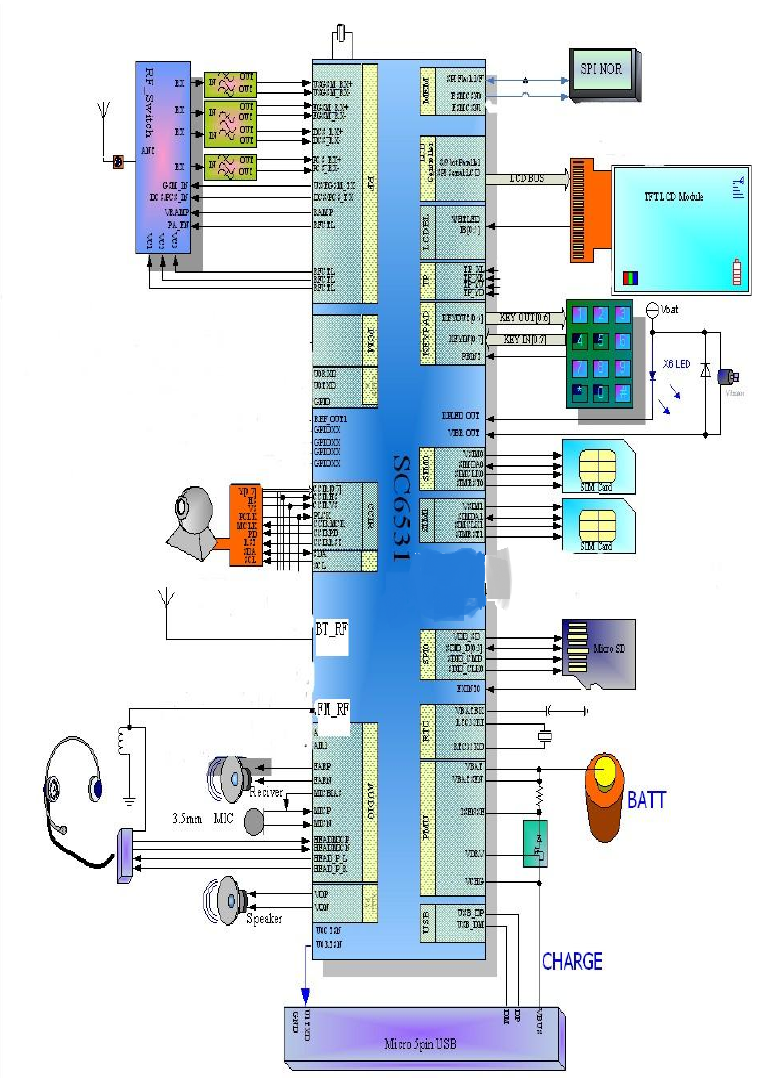
5.1. system diagram
26M
GSM 850:824.2-848.8MHz
1900:1850.2-1909.8MHz
BT 2402-2480 MHz
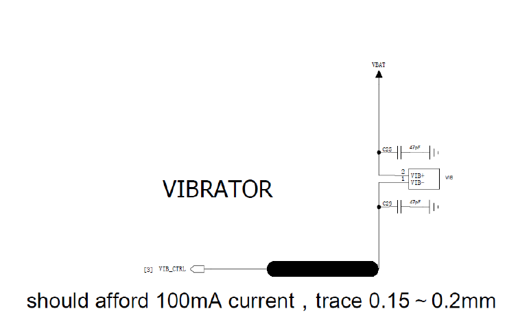
5.2. Vibration issue:
The vibrator circuit is simple, one point connected to VBAT and the other to
VIB_CTRL. VBAT voltage is approximately equal to battery voltage, and VIB_CTRL
voltage outputs from the core chip and is controlled by the software. When vibration
enabled, the differential voltage of the vibrator is close to 3.0 v, when vibration disabled,
the differential voltage is close to 0 v.
Repair steps:
1. Check whether the Vibrator is damaged and the soldering is well or not;
2. Check if the related circuits, ,have soldering issues, etc;
3. Replace with new Vibrator, and verify again;
4. Enable and disable vibration functions respectively, check whether both ends of the
Vibrator voltage are normal or not. If abnormal, check if the U0100 has soldering or
performance problems.
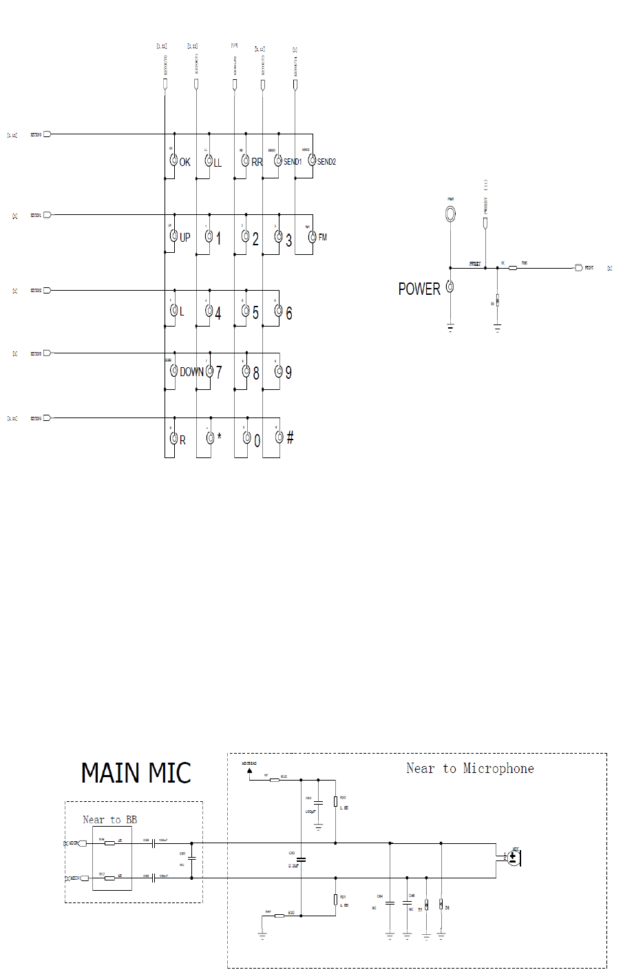
5.3. Keypad/side key function abnormity
There are keys totally. KEYOUT is output for row scan, and KEYIN is input for column
scan;
When some key is pressed, the column detects low level, CPU start the keypad scan program,
judge the key value,
and start the corresponding operation.
Repair steps:
1. Check if keypad and DOME are damaged, the assembly OK ,and foreign matter exist, etc;
2. Check if the surrounding components (mainly varistors) on the main board are damaged and
have soldering issues, etc;
3. Replace with new keypad or side key, and verify again;
4. If you still have not found the problem, then check whether the U1 chip has soldering or
performance problems or not.
5.4. Microphone function abnormity
Repair steps:
1. Check if the microphone and lead is well ,and soldering is well ;
2. Check whether the relevant components have soldering problems or not;
3. Replace with new microphone, and verify again;
4. Enter the call state (or engineering test mode),measuring if microphone’s bias voltage is normal:
the voltage is when the microphone works about 1.8V, and 0V when off;
5. If you still have not found the problem, then check whether the U1 chip has soldering
or performance problems or not.
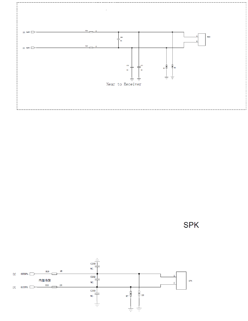
5.5. Receiver function abnormity
Rep
air steps:
1. Check if the receiver shrapnel’s elasticity is well, and contact with PCB well;
2. Check if the relevant components have soldering problems;
3. Replace with new receiver, and verify again;
4. If you still have not found the problem, then check whether the U1 chip has soldering
or performance problems or not.
5.6. Speaker function abnormity
Repair steps:
1. Check if the speaker and the lead are well, and soldering is well;
2. Check if the relevant components have soldering problems;
3. Replace with new speaker, and verify again;
4. If you still have not found the problem, then check whether the U1 chip has soldering
or performance problems or not.
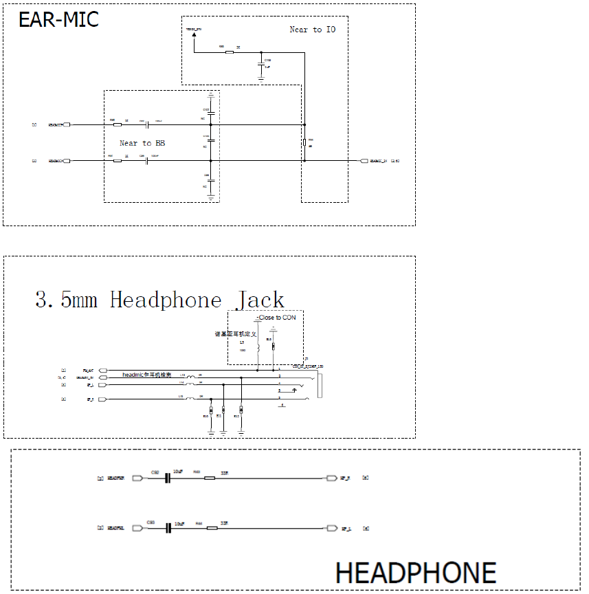
5.7. Earphone function abnormity
F9 earphone is sharing one interface with headphone JACK.
Earphone Detection: when the headset is plugged into the phone, headmic_in signal changes from high
level to low level, and CPU will treat it as “earphones plugged”, and a earphone mark will displayed
accordingly.
Headset microphone on-hook and off-hook principle: generally, there is a hook button on the earphone.
Press the button, then MIC will short-circuit to ground, ADC signal changes from high level to low level,
when the signal is detected as low, and the phone is on incoming call state, then answer the call; if the
phone is on answering call state, then end the call.
Repair steps:
1. Check if the headset can be detected by the phone after being plugged. If cannot, replace with a
new headset and verify again;
2. Check if the relevant components have soldering problems;
3. If you still have not found the problem, then check whether the U1 chip has soldering
or performance problems or not.
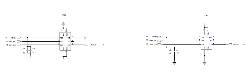
5.8. SIM card theory and repair
F9 has a built-in dual-card management chip, and has two SIM card connectors, supports dual
SIM dual standby.
Repair steps:
1. Check if the dual- cards’ insertion direction is OK;
2. Check if the card connector metal contact points have problems, such as existing foreign
matters or are rusting, etc;
3. Check if the SIM card connectors and components around have soldering problems;
4. If failed to find out problems, check whether U1 chips have soldering or performance
issues.
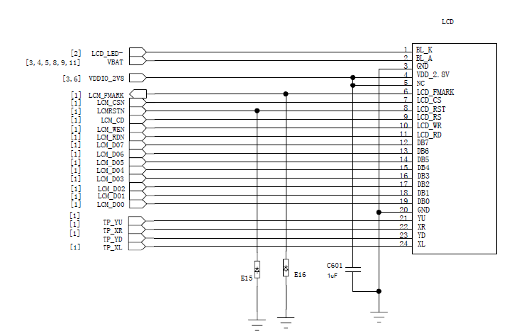
5.9. LCD display abnormity
F9 LCD backlight is directly drive by U1, without extra drive circuit. LCD data and control
lines connect to LCD interface through the capacitor, specific circuit as follows:
Repair steps:
1. Check if the LCD is damaged, and FPC has soldering problems;
2. Check if t h e relevant components h ave soldering problems;
3. Replace with new LCD, and verify again;
4. If still failed to find out problems, check whether U1 chip has soldering or
performance problems.
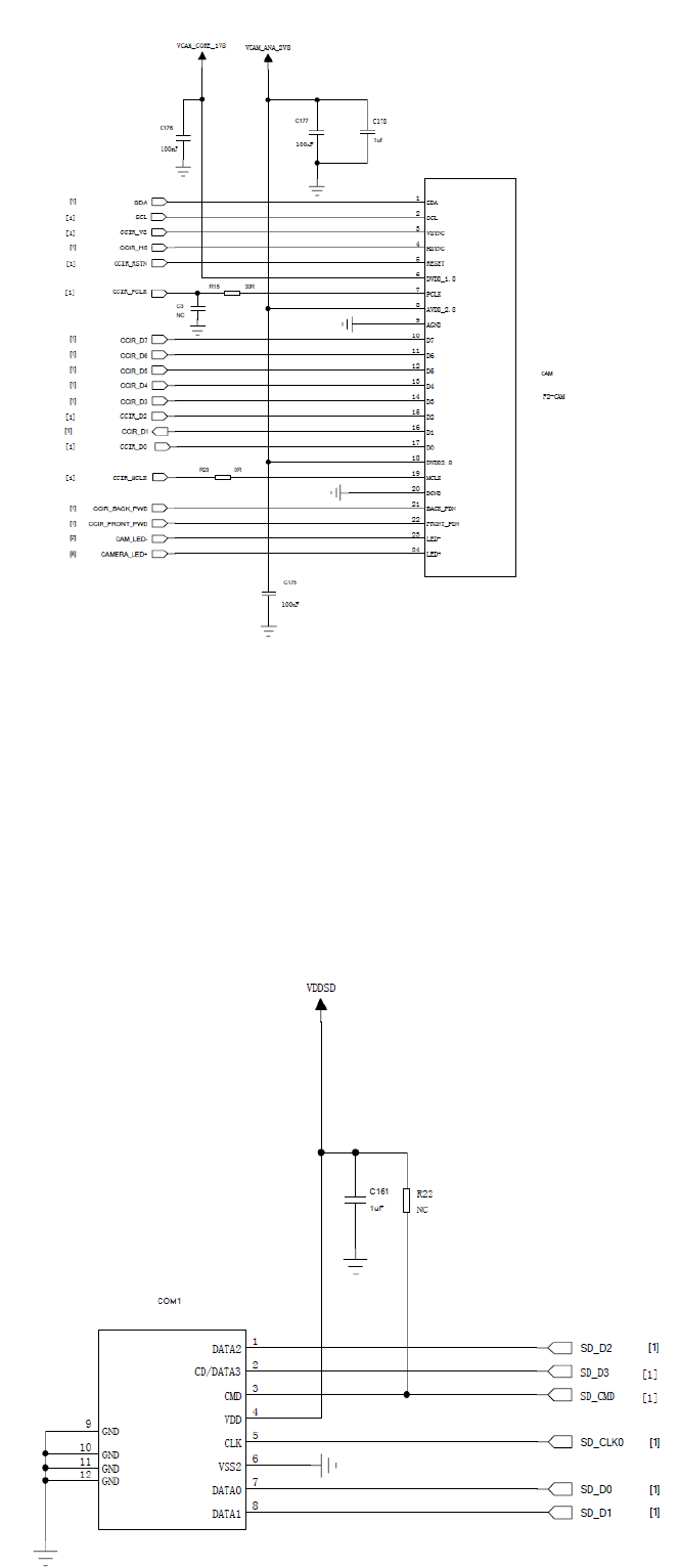
5.10. Camera function abnomity
F9, configured with a 0.3 million pixels main camera, the data and control lines which connect
to the main chip’s camera interface directly. The main camera’s power supply is provided by
U1, Specific circuits as follows:
Repair steps:
1. Check if the camera has quality problem, and FPC has assembly problem;
2. Check if the camera’s power supply voltage is normal, and components around
CAM have soldering problems;
3. Replace with new camera, and verify again.
4. If still failed to find out problems, check whether U1 chip has soldering or
performance problems.
a) T card function abnormity
Repair steps:
1. Check if the T card connector’s COM1 has quality problem, metal contact points abnormal;
2. Check if T card connector and components around have soldering problems;
3. If still failed to find out problems, check whether U1 chip has soldering or
performance problems.
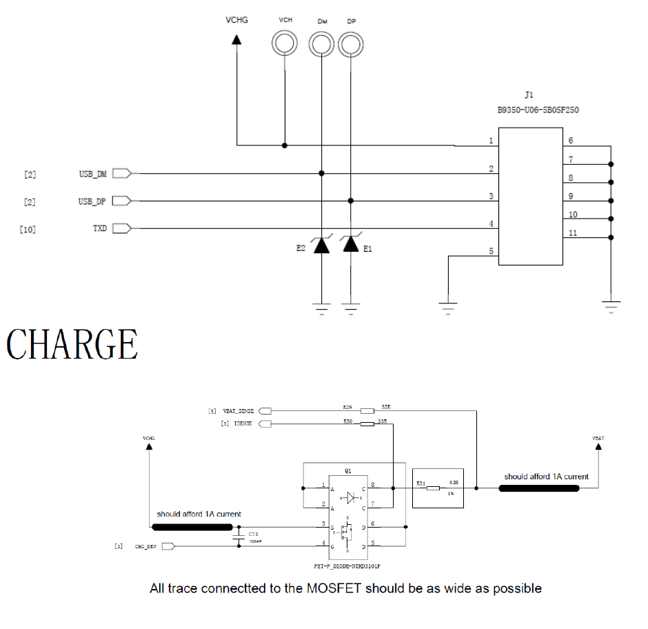
b) Charging function abnormity
Repair steps:
1. Check if the USB J1 socket pins rust or have soldering problems;
2. Check if the battery connector’s metal contact well or not, such as existing foreign
matters, rusting or soldering badly, etc;
3. Check if the relevant components of the charging circuits have soldering problems;
4. Replace with new battery, and verify again;
5. If still failed to find out problems, check whether U1 chip has soldering or
performance problem.
Annex
Baseband functions test under the engineering mode
1. Power on the phone to the idle screen, and input "*#80# " to enter the "test menu";
2. Select “Keypad” function test, and the screen will prompt the current testing key, then press the
key accordingly until all the keys are tested, and exit automatically. If a certain key doesn’t
work or press a wrong key, then the screen will show the key that will test, and exit
automatically in 5 seconds without action.
2. Select “LCD” function test, the screen will display “red, green, blue, white, black” color with
full screen, then exit automatically.
4 Select “Receiver, Loud speaker, Echo Loop,”to Audio” function test
A. Select “Receiver” function test, if need to do aging test for receiver components, you can set
“Play time, Interval time, Loop times” . Otherwise you can press “OK” key to start the Receiver
test directly. And press “OK” key again to change to the speaker test;
B. Select “Loud speaker” function test, if need to do aging test for speaker components, you
can set “Play time, Interval time, Loop times”. Otherwise you can press “OK” key to start the
speaker test directly.
C. Select “EchoLoop” function test, speak to the main microphone, then can hear the voice
from the receiver. Insert the earphones, then press “Ok” key to change to the earphone test. Now
speak to the microphone of the earphone line, then can hear the voice from the earphones.
5 Select “Vibrator” function test, if need to do aging test for the vibrator component, you can set
“Vibrator time, Interval time”. Otherwise press “OK” key to start the vibrator test directly;
6 Select “LED” function test, the LCD backlight flicker, immediately following, the keypad light
will flicker, then exit automatically;
7 Select “Memory Card” function test, the screen displays “Writing…” firstly, after a moment, it
displays “Playing…”, now speaker will play sound, and then exit automatically;
8.Select “FM” function test, you need to insert the earphones to enter the FM mode; press “Left
key” or “Right key” to search channels and receive radio. Press “OK” key to close the FM function
when exiting;
9 .Select “Charger” function test, if the phone has charged through a DC charger or USB
cable, the screen displays “Pass”, otherwise “Please insert charger”;
10. Select “ADC” function test, the screen displays the current voltage and temperature of the
battery;
FCC
FCC RF Exposure Information and Statement
The SAR limit of USA (FCC) is 1.6 W/kg averaged over on one gram of tissue.
Device types: FOREVER (FCCID: 2AB7A-2015) has also been tested against this SAR limit. The
highest SAR value reported under this standard during product certification for use at the ear is
0.250 W/kg and when properly worn on the body is 0.593 W/kg. This device was tested for
typical body-worn operations with the back of the handset kept 1.0 cm from the body. To
maintain compliance with FCC RF exposure requirements, use accessories that maintain a 1.0
cm separation distance between the user's body and the back of the handset.
The use of belt clips, holsters and similar accessories should not contain metallic components in its
assembly. The use of accessories that do not satisfy these requirements may not comply with
FCC RF exposure requirements, and should be avoided.
This device complies with part 15 of the FCC rules. Operation is subject to the following two
conditions: (1) this device may not cause harmful interference, and (2) this device must accept
any interference received, including interference that may cause undesired operation.
NOTE: The manufacturer is not responsible for any radio or TV interference caused by
unauthorized modifications to this equipment. Such modifications could void the user’s
authority to operate the equipment. This equipment has been tested and found to comply with
the limits for a Class B digital device, pursuant to part 15 of the FCC Rules. These limits are
designed to provide reasonable protection against harmful interference in a residential
installation. This equipment generates uses and can radiate radio frequency energy and, if not
installed and used in accordance with the instructions, may cause harmful interference to radio
communications. However, there is no guarantee that interference will not occur in a particular
installation. If this equipment does cause harmful interference to radio or television reception,
which can be determined by turning the equipment off and on, the user is encouraged to try to
correct the interference by one or more of the following measures:
- Reorient or relocate the receiving antenna.
- Increase the separation between the equipment and receiver.
-Connect the equipment into an outlet on a circuit different from that to which the receiver is
connected.
- Consult the dealer or an experienced radio/TV technician for help.
The user’s manual or instruction manual for an intentional or unintentional radiator shall caution the
user that changes or modifications not expressly approved by the party responsible for
compliance could void the user's authority to operate the equipment. In cases where the manual
is provided only in a form other than paper, such as on a computer disk or over the Internet, the
information required by this section may be included in the manual in that alternative form,