HL Tech WL-3002 WLAN 802.11b/g miniPCI card User Manual WL 3002 user guide 0518
HL-Tech Corporation WLAN 802.11b/g miniPCI card WL 3002 user guide 0518
HL Tech >
Users Manual
WLAN 802.11 b/g MiniPCI
WL-3002
Hardware Installation and
Configuration Utility User’s Guide
Integrated Baseband and MAC Solution
IEEE 802.11b/g WLAN

WL-3002 User’s Manual
HL-TECH Corporation 2
Contents:
Table of Contents .……….……….………..……….…………...2
Introduction ….…………………………………………………..3
Install the WLAN card in PC/NB………….……….….………..4
Install WL-3002 driver…….………………….…….…………..5
Setup WL-3002 Configuration Utility…………….…………….7
WL-3002 User’s Manual
HL-TECH Corporation 3
Introduction
The Wireless LAN Configuration Utility is a powerful application that helps you to
configure this WLAN card and monitor the statistics of the communication status. Unlike
the standard method of configuring the card via the operating system utilities, this
application permits the dynamic modification of the configuration parameters while the
card is operating. It also offers more configuration options.
We offer the Wireless LAN Configuration Utility for Windows® 98SE/Me/2000/XP.
Mini-PCI WLAN equipment has been tested and found to comply with limits for a Class
B digital device, pursuant to Part 15 of the FCC rules. These limits are designed to
provide reasonable protection against harmful interference in residential installations.
This equipment generates, uses, and can radiate radio frequency energy, and if not
installed and used in accordance with the instructions, may cause harmful interference to
radio communications.

WL-3002 User’s Manual
HL-TECH Corporation 4
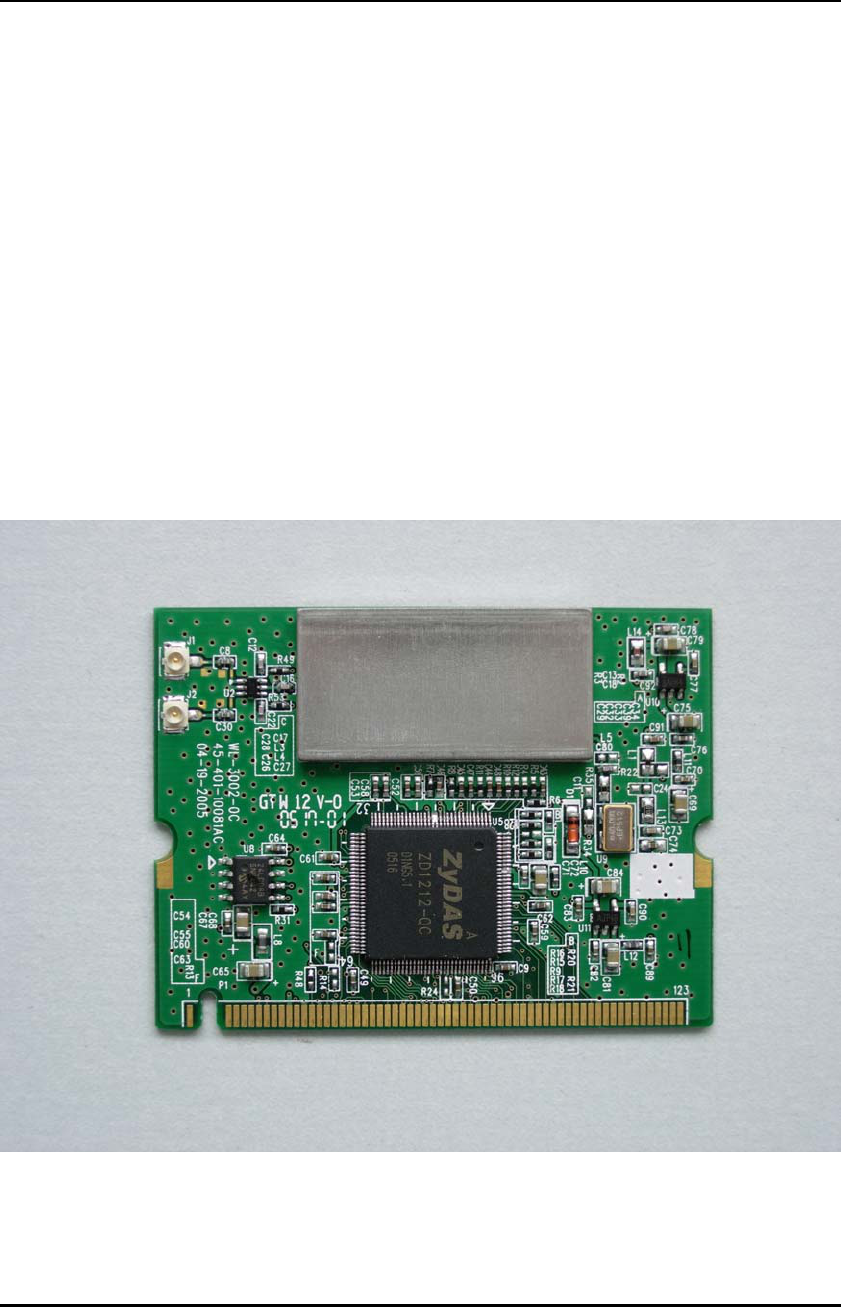
Install the WLAN card in PC/NB
Release the screw from PC/NB
Find out the pre-wired cable
Connect the cable with Mini-PCI
Align and firmly plug the Mini-PCI card
into the slot.
Re-place the cover to PC/NB
Secure the screw with a cross screwdriver.
WL-3002 User’s Manual
HL-TECH Corporation 5
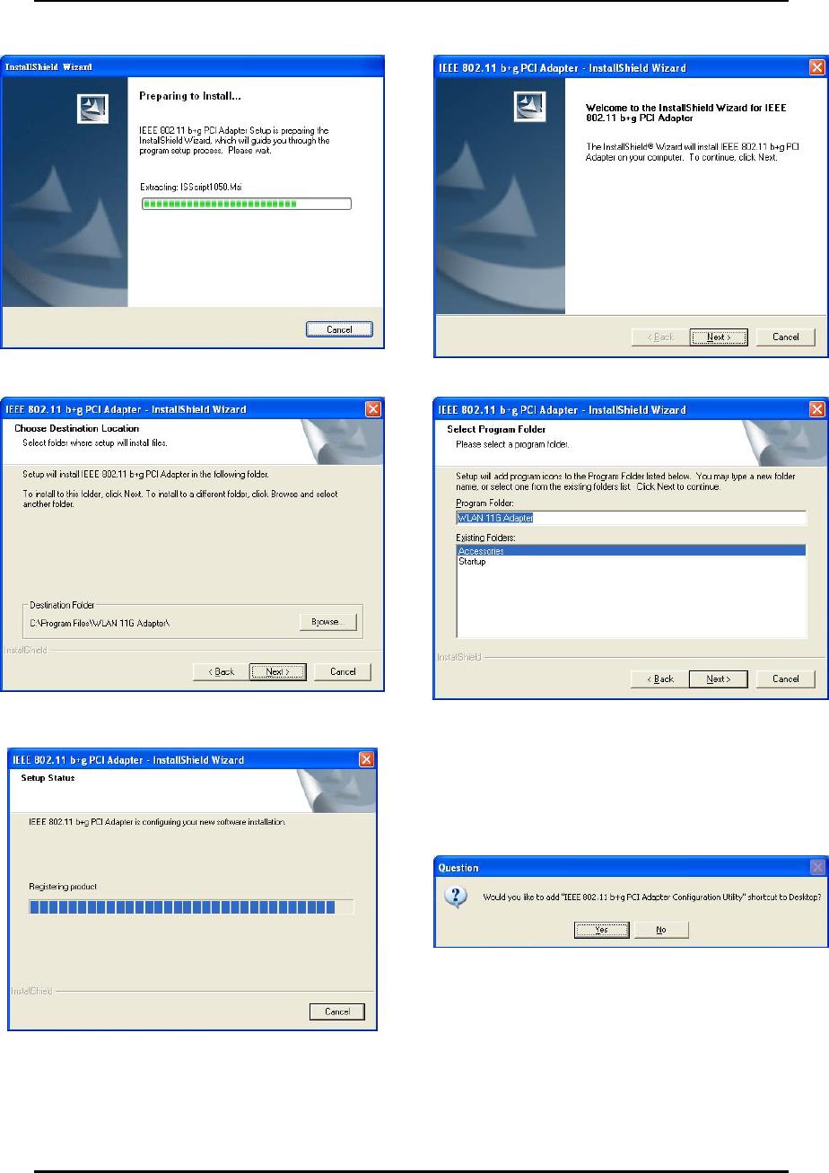
Install WL-3002 driver
The program will automatically proceed with
installing.
Press “Next” to continue
Press “Browser” to change the folder where setup
will install files or press “Next” to continue.
Select or create a program folder and press
“Next” to continue.
The program will automatically proceed with
installing.
Press “Yes” to continue.
WL-3002 User’s Manual
HL-TECH Corporation 6
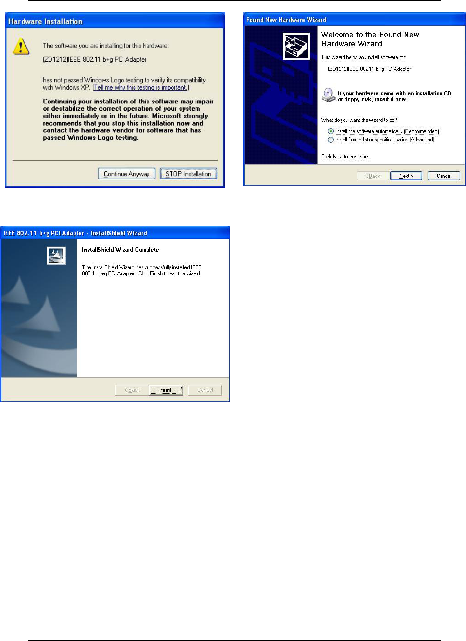
Press “Continue” to continue the process. Insert the Wireless Card to slot of NB and choose
“Install the software automatically
(Recommended)” and press “Next”.
Press “Finish” to complete the installation
WL-3002 User’s Manual
HL-TECH Corporation 7
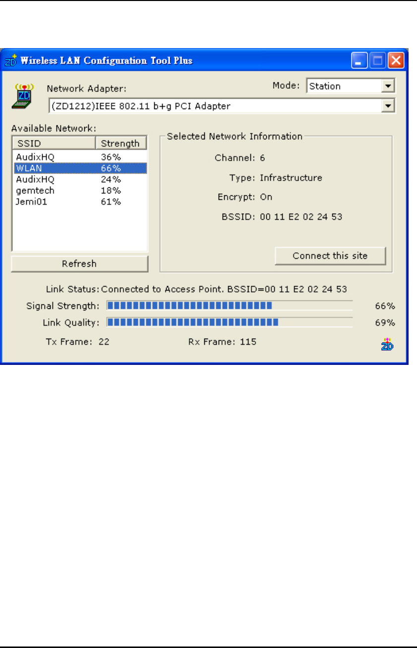
Setup WL-3002 Configuration Utility
1. Station:
Figure 1-1
Open the WL-3002 Configuration Utility shown as Figure 1-1. The adapter can be set at
“Station” or “Access Point” Mode from the Mode drop down menu. Station mode is
selected for the item.
You can site survey the neighboring SSID site by pressing the “Refresh”, then sites
name and signals strength of available SSID sites are shown on the “Available
Network” field.
Double click the SSID site from “Available Network” field, and the SSID can be
connected directly.
The information of the SSID is shown on the “ Current Network Information”.
Show the BSSID of connecting AP on the “Link Status” filed.
“Signal Strength” and “Link Quality” shown on diagrammatic curve, and described
with percentage.
Record the number of Tx frames on the filed of “Tx Frame”.
Record the number of Rx frames on the filed of “Rx Frame”.
WL-3002 User’s Manual
HL-TECH Corporation 8
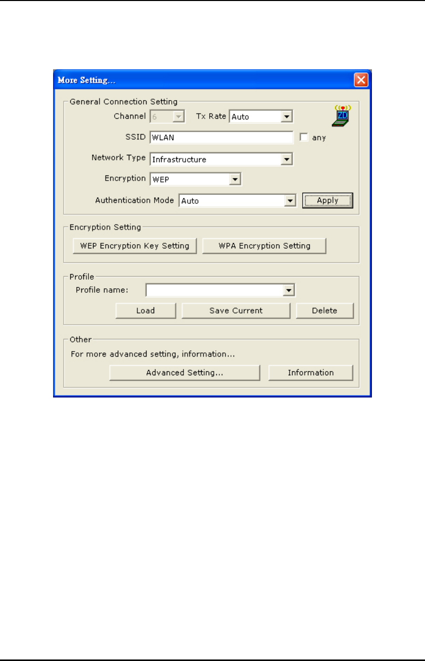
1.1 More Setting
Press “Connetc this site “ in Figure 1-1to enter “More setting“ window.
Figure 1-2
1.1.1 “General Connection Setting” group:
Read the current status from the group if the “Change” button is not pressed.
Press “Change” button for modifying the status, when the modification is finished,
press “Apply” to save it. The button “Change” and “Apply” is alternately shown on
the same position.
Modify the SSID name from the “SSID” field. When use the item, the “any “will be
unchecked previously.
Change the channel by drop down menu “ Channel”. When use the item, the
Ad_Hoc Mode will be set previously.
Select the transmission rate by “ Tx Rate” drop down menu.
Select the “Ad_Hoc” or “Infrastructure” Mode by the “Network Type”
drop down menu.
Select the “Enable WEP” or “Disable WEP” by the “Encryption” drop
down menu.
Select the “Open System” , “Shared Key” mode or “Auto” from the
“Authentication Mode” drop down menu.
WL-3002 User’s Manual
HL-TECH Corporation 9
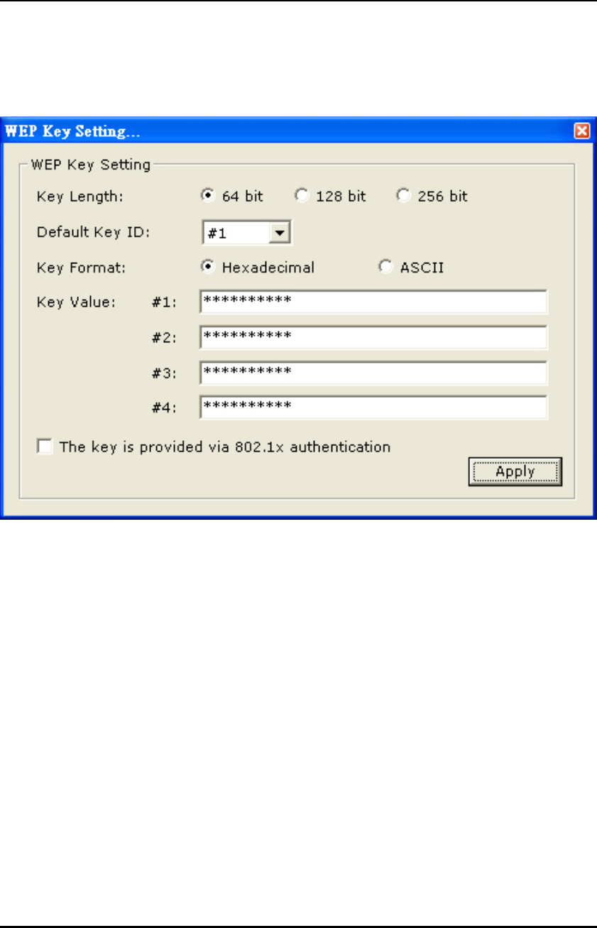
1.1.2 Encryption Setting
1.1.2.1 WEP Key Setting
Press “WEP Encryption Setting” in Figure 1-2 to enter the “WEP Key Setting” page
Figure 1-3
Select the “Open System” , “Shared Key” mode or “Auto” from the “authentication
Mode” drop down menu.
Press the “Change” button to modify the contents of “WEP Key setting”, when it is
finished, press “Apply” to save it. The button “Change” and “Apply” is alternately
shown on the same position.
Select which key length 64,128 or 256 bits will be modified or used by “Key
Length” item.
Select which key set will be use by the field of “Default Key ID”
Modify the 4 sets key depending on the selected key length on the field of “Key
Value”. The key value is used the hexadecimal format.
Select which key format “hexadecimal” or “ASCII” will be used from the “Key
Format”
WL-3002 User’s Manual
HL-TECH Corporation 10
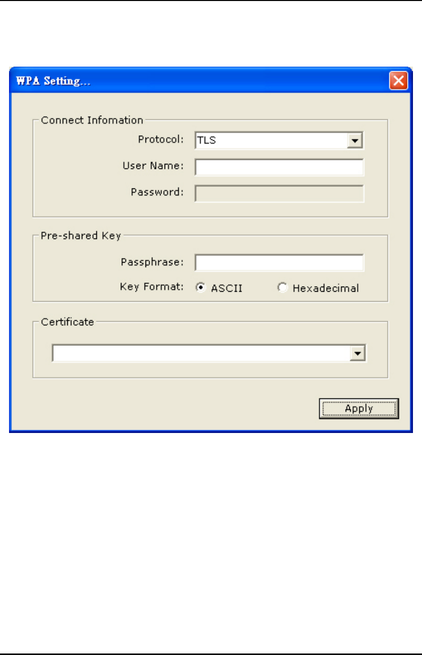
1.1.2.2 WPA Setting
Press “WPA Encryption Setting” in Figure 1-2 to enter the “WPA Setting” page
Figure 1-4
You can select the WPA authentication protocol “TLS” or “PEAP” from “Protocol”
filed. The TLS is used , the User name and Password need not to be used , but the
Certificate need to be used. If the PEAP is used , the User name , Password and
Certificate need to be used.
If you select “pre-share-key” protocol , you can write down your password on the
filed of “Passphrase” , the password length can be selected from 8 bytes to 63 bytes
(ASCII format) depend on user .
WL-3002 User’s Manual
HL-TECH Corporation 11
1.1.3 Setup Profile Group:
Figure 1-5
Select the profile that has been saved previously from the “Profile name” drop down
menu, then press “Load ” button to load the status to use.
Write the profile name on the field of “Profile name”, and press the “Save Current”
button to save the current status on the profile.
Select the profile name that wanted to delete from the “Profile name” drop down
menu, and press “Delete” button to delete it
WL-3002 User’s Manual
HL-TECH Corporation 12
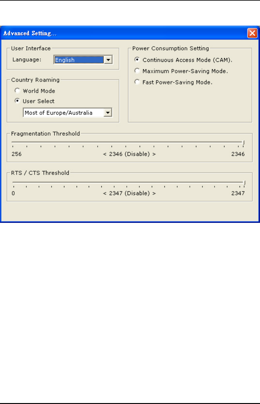
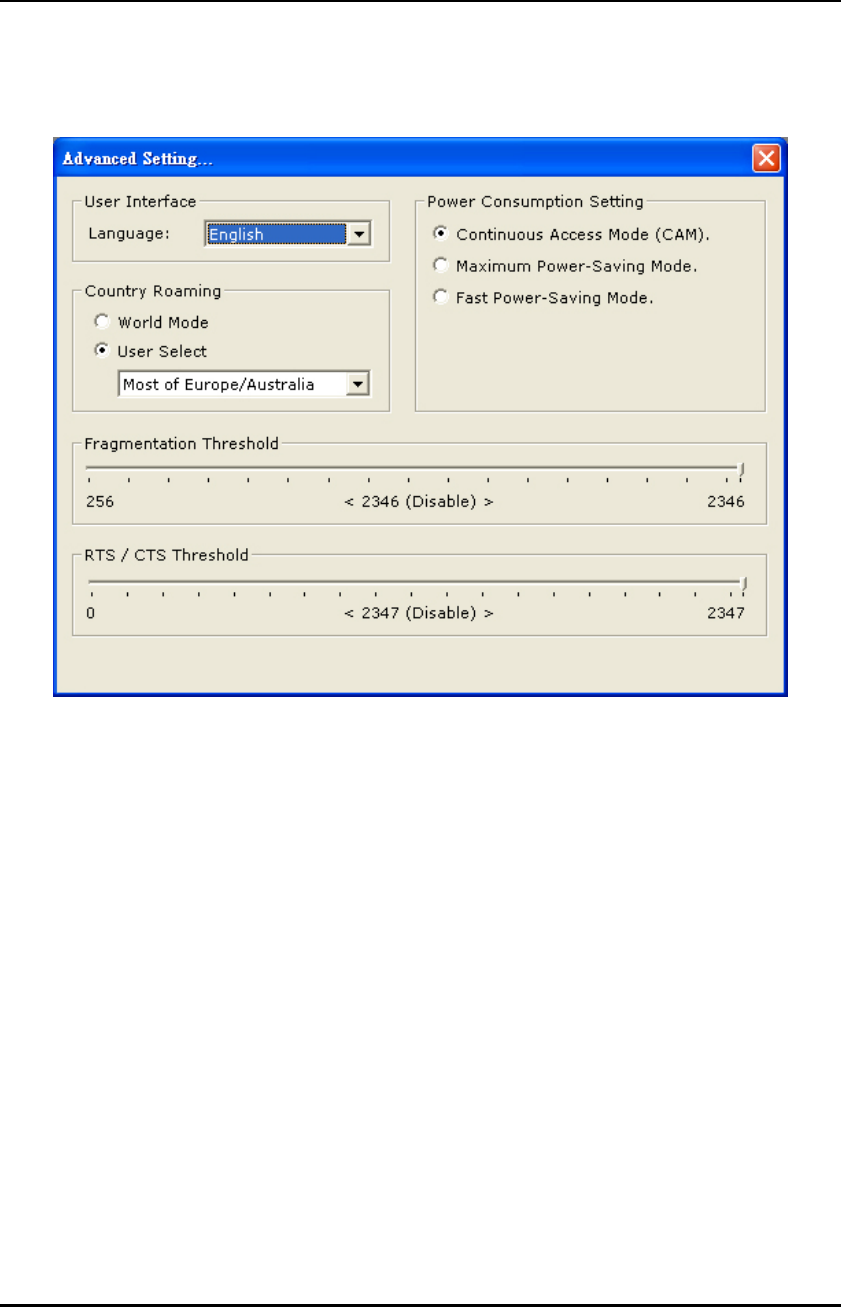
1.1.4 Setup Other Group:
Press “Advanced setting” in Figure 1-2 to enter the “Advanced setting” page.
Figure 1-6
Select the Window User Interface by the “Language” down drop menu. If the
English item is selected, all functions of window are described with English. Select
the Traditional Chinese item, and they are described with Traditional Chinese.
At “Power consumption Setting” group, select which power save level want to be set
by checking CAM Mode, Maximum Power-Saving mode or Fast Power-Saving
mode. The default is CAM mode. If the most save mode want to use, select the
Maximum Power-Saving mode, but it throughput is lower than CAM and Fast
Power-Saving mode. The throughput of “Fast Power-Saving mode” is better than
“Maximum Power-Saving mode”, but its power save is less than “Maximum
Power-Saving mode”.
At “Country Roaming” group, the default depends on the region of EEPROM.
Select other region from “User Select” drop down menu, or check “World Mode”
item to set it to the word mode. When the word mode is set, it depends on the
behavior of AP. If the WLAN card is re-plug , the setting will return to default
setting.
At “Fragmentation Threshold” bar, drop and move cursor to set the fragmentation
threshold point, the range is from 256 to 2346 bytes.
At “RTS / CTS Threshold” bar, drop and move the cursor to set the RTS threshold
point, the range is from 0 to 2347 bytes.
WL-3002 User’s Manual
HL-TECH Corporation 13
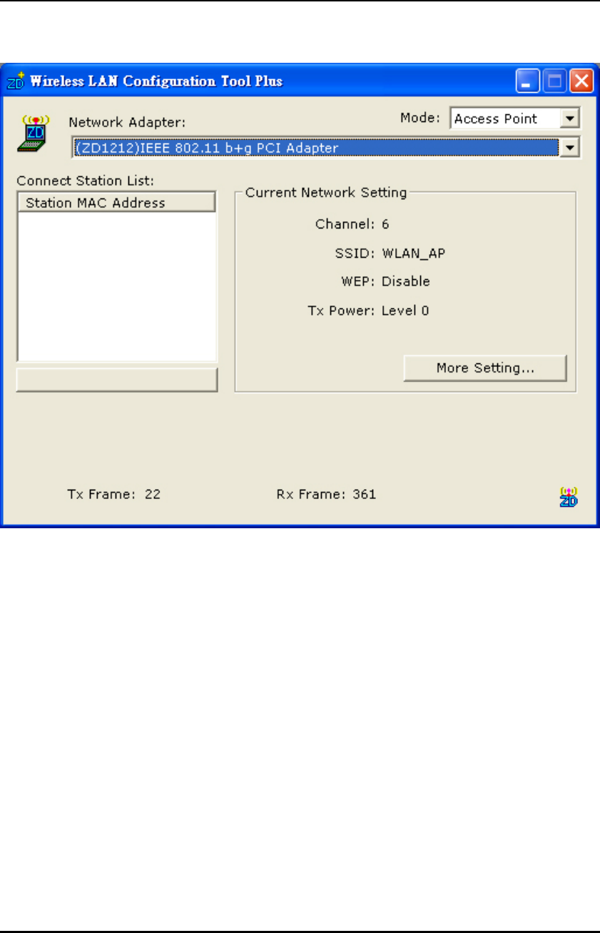
2. Access Point
Figure 2-1
Open the WL-3002 Configuration Utility shown as Figure 2-1. For the soft AP, please
option the “ Access Point” from drop down menu Mode filed.
“Network Adapter” shows the available WLAN card for soft AP.
If the WLAN stations link to the Soft AP , their MAC address will be shown on the
filed of the “Station MAC Address”.
The current status of the AP is shown on the “current Network Setting”. It can show
which Channel is used, and what is the AP’s SSID. You can know if the WEP is
disable or enable. The Tx power level is shown on it too (The is function not
available now).
The Tx Frame shows how many frames transmitted by the soft AP.
The Rx Frame shows how many frames received by the soft AP.
WL-3002 User’s Manual
HL-TECH Corporation 14
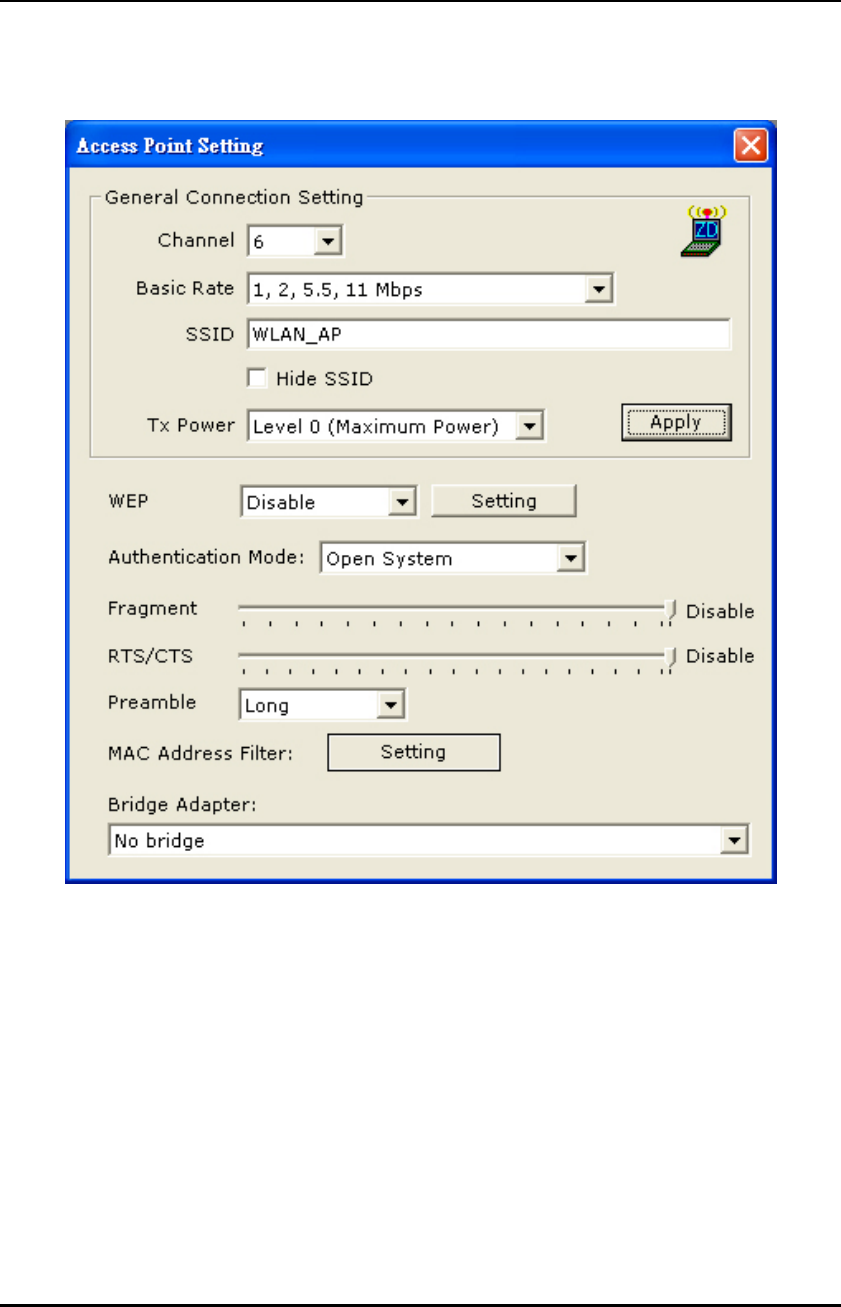
2.1 Access Point Setting
Press “More Setting” in Figure 2-1 to enter the “Access Point Setting” page.
Figure 2-2
Select the “Open System” or “Shared Key” mode from the “authentication Mode”
drop down menu.
At “Fragment” bar, drop and move cursor to set the fragmentation threshold point,
the range is from 256 to 2346 (Disable) bytes.
At “RTS / CTS” bar, drop and move the cursor to set the RTS/CTS threshold point,
the range is from 0 to 2347(Disable) bytes.
Select the Long preamble or Short preamble from the “Preamble” drop down menu.
Select the NIC card for bridge function from the filed of drop menu “Bridge
Adapter”. If the bridge function will be disable, please select the “ No bridge” item
from “Bridge Adapter”.
Note: The maximum number of channels permitted by local regulations: 1 ~ 11channels for the
United States / 1~13 channels for the EU.
WL-3002 User’s Manual
HL-TECH Corporation 15
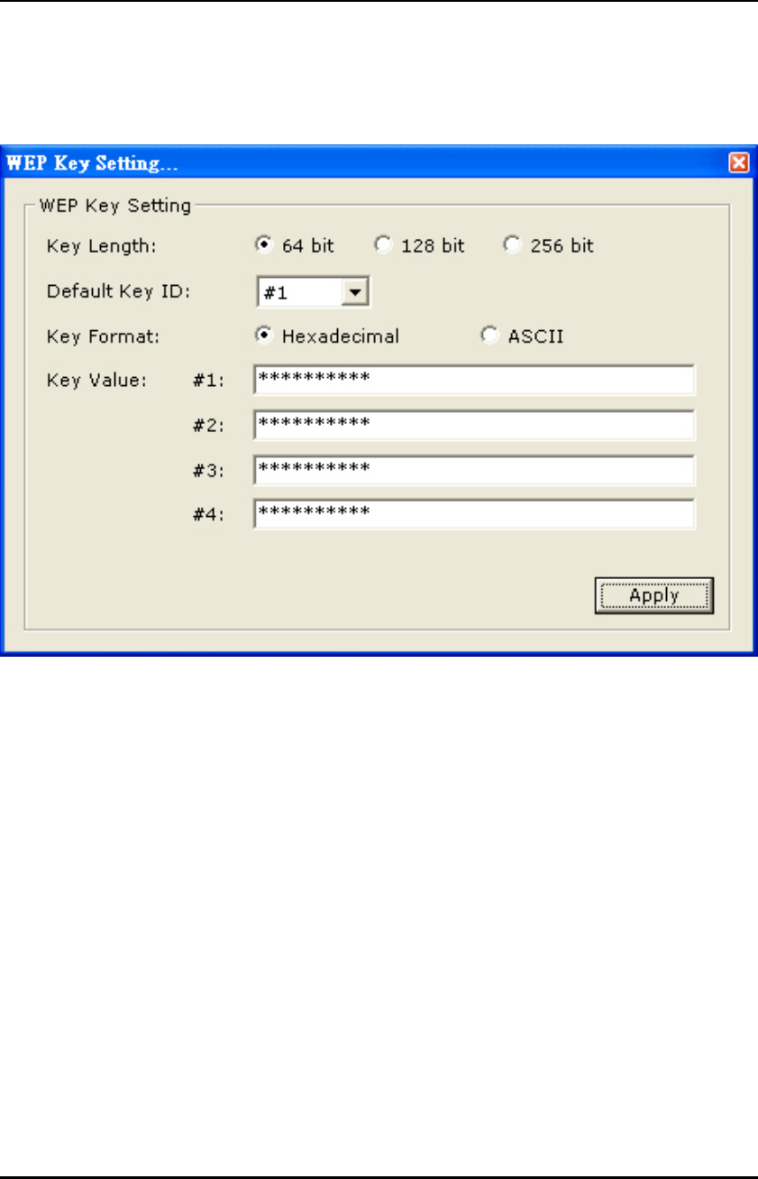
2.1.1 WEP Key Setting
Press the “Setting” icon of WEP in Figure 2-2 to open the “WEP key setting” shown as
Figure 2-3.
Figure 2-3
Modify the contents of “WEP Key setting”, when it is finished, press “Apply” to
save it. Select which key length 64,128 or 256 bits will be modified or used by “Key
Length” item. Select which key set will be use by the field of “Default Key ID”.
Modify the 4 sets key depending on the selected key length on the field of “Key
Value”. The key value is used the hexadecimal format. Select which key format
“Hexadecimal” or “ASCII” will be used from the “Key Format”.
WL-3002 User’s Manual
HL-TECH Corporation 16
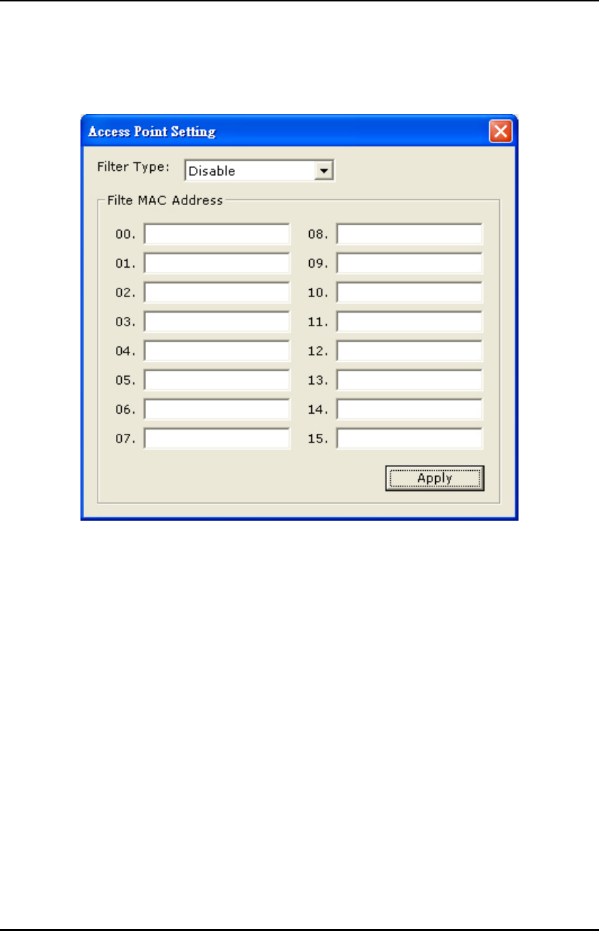
2.1.2 Access Point Setting
Press the “Setting” icon of MAC Address Filter to enter access point setting to fill the
MAC addresses that will be accepted or filtered..
Figure 2-4
Select “Disable” or “Accept” or “Filter” from the filed of drop menu “Filter Type”.
There are 16 sets MAC addresses can be filled on the “Filter MAC Address”. If all
setting is finished, please press Apply to save it.

WL-3002 User’s Manual
HL-TECH Corporation 17
Federal Communications Commission (FCC) Requirements
This equipment has been tested and found to comply with the limits for a Class B digital
device, pursuant to part 15 of the FCC rules. These limits are designed to provide
reasonable protection against harmful interference in a residential installation. This
equipment generates, uses and can radiate radio frequency energy and, if not installed and
used in accordance with the instructions, may cause harmful interference to radio
communications. However, there is no guarantee that interference will not occur in a
particular installation. If this equipment does cause harmful interference to radio or
television reception, which can be determined by turning the equipment off and on, the
user is encouraged to try to correct the interference by one or more of the following
measures:
-Reorient or relocate the receiving antenna.
-Increase the separation between the equipment and receiver.
-Connect the equipment into an outlet on a circuit different from that to which the
receiver is connected.
-Consult the dealer or an experienced radio/TV technician for help.
This Transmitter must not be co-located or operating in conjunction with any other antenna or
transmitter.
Any changes or modifications (including the antennas) made to this device that are not expressly
approved by the manufacturer may void the user’s authority to operate the equipment.
This device complies with Part 15 of the FCC Rules. Operation is subject to the following two
conditions:
(1) This device may not cause harmful interference.
(2) This device must accept any interference received, including interference that may cause
undesired operation.
This device is intended only form OEM integrators under the following conditions:
1) The antenna must be installed such that 20cm is maintained between the antenna and users,
and
2) The transmitter module may not be co-located with any other transmitter or antenna.
IMPORTANT NOTE: In the event that these conditions can not be met (for example certain laptop
configurations or co-location with another transmitter), then the FCC authorization is no longer
considered valid and the FCC ID can not be used on the final product. In these circumstances, the
OEM integrator will be responsible for re-evaluating the end product (including the transmitter) and
obtaining a separate FCC authorization.
End Product Labeling
This transmitter module is authorized only for use in devices where the antenna may be installed
such that 20 cm may be maintained between the antenna and users. The final end product must
be labeled in visible area with the following:
“Contains TX FCC ID: SLH-WL-3002”
End Product Manual Information
The user manual for end users must include the following information in a prominent location
“IMPORTANT NOTE: To comply with FCC RF exposure compliance requirements, the antenna
used for this transmitter must be installed to provide a separation distance of at least 20cm from all
persons and must not be co-located or operating in conjunction with any other antenna or
transmitter.”