HM Electronics 1404 Wireless belt pack transceiver User Manual
HM Electronics Inc Wireless belt pack transceiver Users Manual
Users Manual


Table of Contents
1. EQUIPMENT DESCRIPTION...................................................................................................................................... 1
1.1 Wireless IQ Base Station .................................................................................................................................................. 2
1.1.1 External Features............................................................................................................................................................... 2
1.2 COMMUNICATOR®s ...................................................................................................................................................... 4
1.2.1 Features and Controls ........................................................................................................................................................ 4
1.2.2 How to Wear the COMMUNICATOR® ........................................................................................................................... 4
1.2.3 How to Use the COMMUNICATOR® Controls ............................................................................................................... 5
1.2.4 COMMUNICATOR® Registration ................................................................................................................................... 5
1.2.5 Battery Removal and Replacement ................................................................................................................................... 7
1.3 Battery Charger ................................................................................................................................................................. 8
2. PREPARATION FOR INSTALLATION ..................................................................................................................... 9
2.1 Tools Required .................................................................................................................................................................. 9
2.2 Battery Charger Setup and Battery Charging .................................................................................................................... 9
2.2.1 Battery Charger Setup for Use In the United States .......................................................................................................... 9
2.2.2 Battery Charger Setup for Use Outside the United States .................................................................................................... 10
2.2.3 Battery Charging ............................................................................................................................................................. 10
2.3 Interference Prevention ................................................................................................................................................... 11
2.3.1 Radio Frequency (RF) Interference ................................................................................................................................. 11
2.3.2 Electrical Interference ..................................................................................................................................................... 12
3. EQUIPMENT INSTALLATION ................................................................................................................................. 13
3.1 Base Station Installation .................................................................................................................................................. 13
3.1.1 Walk Test for Best Transmission/Reception ................................................................................................................... 14
3.1.2 Mount Base Station on Wall ........................................................................................................................................... 15
3.1.3 Install Remote Antenna Kit (if needed)........................................................................................................................... 15
3.2 Cable Pulling ................................................................................................................................................................... 17
3.3 Outside Speaker and Microphone Installation and Cable Connections .......................................................................... 17
3.3.1 Microphone Installation .................................................................................................................................................. 18
3.3.2 SP2500LP Low-Profile Speaker Installation ................................................................................................................... 19
3.4 Optional SP2000A Speaker/Microphone Installation .......................................................................................................... 20
3.5 Optional External Vehicle Detector Installation ............................................................................................................. 21
3.6 Optional HME Vehicle Detector Board (VDB) Installation ........................................................................................... 21
3.7 External Message Repeater Installation .......................................................................................................................... 22
4. EQUIPMENT SETUP .................................................................................................................................................. 23
4.1 Internal Message Repeater Setup .................................................................................................................................... 23
4.2 Early Warning Setup ....................................................................................................................................................... 23
4.3 Dual-Lane Setup ............................................................................................................................................................. 23
4.4 Split-B Audio Setup ........................................................................................................................................................ 23
4.5 Auto-Hands-Free Setup ................................................................................................................................................... 23
5. SYSTEM FUNCTIONAL CHECK ............................................................................................................................. 24
5.1 Noise Reduction Adjustment .......................................................................................................................................... 24
5.2 VAA (Voice Activated Attenuation) Adjustment ........................................................................................................... 25
6. WIRELESS IQ OPERATION ..................................................................................................................................... 26
6.1 Changing Languages ....................................................................................................................................................... 26
6.2 Obtaining COMMUNICATOR® Status .......................................................................................................................... 26
6.3 Single-Lane Operation (one base station for one speaker post in one lane) ................................................................... 27
6.4 Dual-Lane Operation (two base stations for two speaker posts in two lanes) ................................................................... 28
6.5 Tandem Operation (two base stations for two speaker posts in one lane) ....................................................................... 29
6.6 Internal Communication .................................................................................................................................................. 30
6.7 Speed-Team Operation.................................................................................................................................................... 31
6.8 Wired Backup System ..................................................................................................................................................... 31
6.9 Message Repeater Operation ........................................................................................................................................... 31
6.9.1 Recording Messages ....................................................................................................................................................... 31
6.9.2 Message Repeater Switch Settings .................................................................................................................................. 32
7. IN CASE OF PROBLEMS ........................................................................................................................................... 33
8. EQUIPMENT SPECIFICATIONS ............................................................................................................................. 38
9. BLOCK DIAGRAM ..................................................................................................................................................... 39
10. BASE INTERFACE DESCRIPTION ......................................................................................................................... 40
10.1 Audio Circuit Board ........................................................................................................................................................ 40
10.2 Transceiver Circuit Board ............................................................................................................................................... 41
10.3 Switcher Circuit Board .................................................................................................................................................... 42
10.4 Vehicle Detector Circuit Board (Optional) ..................................................................................................................... 42
11. WIRING DIAGRAMS.................................................................................................................................................. 43

Figures and Diagrams
Figure 1. Wireless IQ standard equipment ............................................................................................................... 1
Figure 2. Base station with front door open.............................................................................................................. 2
Figure 3. Communicator controls ............................................................................................................................. 4
Figure 4. Correct wearing of the headset .................................................................................................................. 4
Figure 5. Registration buttons and indicators ........................................................................................................... 6
Figure 6. Belt-pac battery-release latch .................................................................................................................... 7
Figure 7. Headset battery-release latch ..................................................................................................................... 7
Figure 8. Batteries in charger ................................................................................................................................... 8
Figure 9. Battery charger AC adapter connection .................................................................................................... 9
Figure 10. 230VAC adapter wiring for battery charger .......................................................................................... 10
Figure 11. Typical drive-thru store layout ............................................................................................................... 13
Figure 12. Typical tandem and dual drive-thru layouts ............................................................................................ 14
Figure 13. Open base station showing four screw holes ........................................................................................... 15
Figure 14. Remote antenna mounting on wall bracket ............................................................................................ 16
Figure 15. Microphone ............................................................................................................................................ 18
Figure 16. Microphone unit and foam inserts shown in typical speaker post installation ....................................... 18
Figure 17. Open the low-profile speaker ................................................................................................................. 19
Figure 18. Mark speaker post or menu board through wire hole in rear panel of SP2500LP
speaker assembly ................................................................................................................................... 19
Figure 19. Screw the self-tapping screws through holes in rear panel of SP2500LP speaker box .......................... 19
Figure 20. SP2500LP cable connections .................................................................................................................. 19
Figure 21. Installing the SP2000A .......................................................................................................................... 20
Figure 22. SP2000A cable connection ..................................................................................................................... 20
Figure 23. External message repeater connections .................................................................................................. 22
Figure 24. Typical tandem drive-thru layout ........................................................................................................... 29
Figure 25. S2 switch on Switcher Board .................................................................................................................. 31
Figure 26. Base Station internal controls and indicators ......................................................................................... 35
Figure 27. Base station jumper settings ................................................................................................................... 36
Figure 28. Base station DIP switch functions .......................................................................................................... 37
Figure 29. Typical Wireless IQ Base Station block diagram .................................................................................... 39
Wiring Diagrams ....................................................................................................................................... 43
Figure 30. Full-Duplex Wireless IQ with VDB but no Switcher Board ..................................................................... 44
Figure 31. Full-Duplex Wireless IQ with VDB, Switcher Board, DM1 or DM3 Microphone and IC300 ................. 45
Figure 32. Full-Duplex Wireless IQ with VDB, Switcher Board and DM1 or DM3 Microphone ............................. 46
Figure 33. Half-Duplex Wireless IQ with VDB but no Switcher Board .................................................................... 47
Figure 34. Half-Duplex Wireless IQ with VDB and Switcher Board ........................................................................ 48
Figure 35. Dual-Lane Wireless IQ Primary to Secondary Base Station Connections ................................................ 49
Figure 36. Tandem Wireless IQ Primary to Secondary Base Station Connections ................................................... 50
© 2015 HM Electronics, Inc.
The HME logo and product names are registered trademarks of HM Electronics, Inc. All rights reserved.
Illustrations in this publication are approximate representations of
the actual equipment, and may not be exactly as the equipment appears.
HM Electronics, Inc. is not responsible for equipment malfunctions due to erroneous translation of
its installation and/or operating publications from their original English versions.

FCC NOTICE
This device complies with Part 15 of the FCC rules. Operation is subject to the following two
conditions: (1) This device may not cause harmful interference, and (2) This device must
accept any interference received, including interference that may cause undesired operation.
This equipment has been tested and found to comply with the limits for a Class A
digital device, pursuant to Part 15 of the FCC rules. These limits are designed to provide
reasonable protection against harmful interference when the equipment is operated in a
commercial environment. This equipment generates, uses and can radiate radio frequency
energy and, if not installed and used in accordance with the instruction manual, may cause
harmful interference to radio communication. Operation of this equipment in a residential
area is likely to cause harmful interference, in which case the user will be required to correct
the interference at his own expense.
Changes or modifications not expressly approved by HM Electronics, Inc. could void the users
authority to operate this equipment.
The antenna(s) used for the base transmitter must be installed to provide a separation distance of
at least 7.87 inches (20 cm) from all persons, and must not be co-located or operating in
conjunction with any other antenna or transmitter.
This device has been designed to operate with the antennas or antenna kits listed below, and having
a maximum gain of 2dBi. Antennas/Kits not included in this list or having a gain greater than 2dBi
are strictly prohibited for use with this device. The required antenna impedance is 50 ohms.
1. Antenna: NEARSON, S181TR-2450R, 2dBi
2. Antenna Kit: HME, EC20 (P/N G28493-1), 0dBi
Industry Canada (IC)
This device complies with Industry Canada license exempt RSS standard(s). Operation is
subject to the following two conditions: (1) this device may not cause interference, and (2) this
device must accept any interference received, including interference that may cause undesired
operation of the device.
This device complies with Health Canada’s Safety Code. The installer of this device should
ensure that RF radiation is not emitted in excess of the Health Canada’s requirement.
Information can be obtained at http://www.hc-sc.gc.ca/ewh-sem/pubs/radiation/radio_guide-
lignes_direct-eng.php
“Changes or modifications not expressly approved by the party responsible for compliance
could void the user’s authority to operate the equipment.”
Hereby, HM Electronics, Inc. declares that the Wireless IQ System is in compliance with the
essential requirements and other relevant provisions of R&TTE Directive 1999/5/EC.

IMPORTANT!
Waste Electrical and Electronic Equipment (WEEE)
The European Union (EU) WEEE Directive (2002/96/EC) places an obligation on producers
(manufacturers, distributors and/or retailers) to take-back electronic products at the end of
their useful life. The WEEE Directive covers most HME products being sold into the EU as of
August 13, 2005. Manufacturers, distributors and retailers are obliged to finance the costs of
recovery from municipal collection points, reuse, and recycling of specified percentages per the
WEEE requirements.
Instructions for Disposal of WEEE by Users in the European Union
The symbol shown below is on the product or on its packaging which indicates that this
product was put on the market after August 13, 2005 and must not be disposed of with other
waste. Instead, it is the user’s responsibility to dispose of the user’s waste equipment by
handing it over to a designated collection point for the recycling of WEEE. The separate
collection and recycling of waste equipment at the time of disposal will help to conserve natural
resources and ensure that it is recycled in a manner that protects human health and the
environment. For more information about where you can drop off your waste equipment for
recycling, please contact your local authority, your household waste disposal service or the
seller from whom you purchased the product.
1
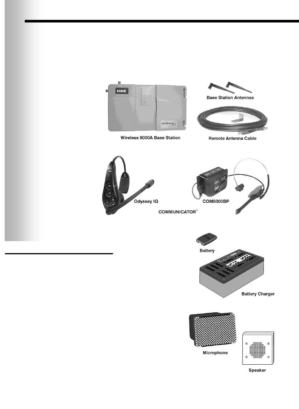
1. EQUIPMENT DESCRIPTION
The Wireless IQ is an audio system primarily for use at quick-service restaurants.
The equipment shown below is standard with each Wireless IQ system. Optional
equipment can be ordered from your local dealer.
As you unpack the Wireless IQ, check the packing list for each item to verify receipt
of all equipment and quantities listed.
Figure 1. Wireless IQ standard equipment
OPTIONAL EQUIPMENT
Equipment Model Number
Belt-Pac Communicator COM6000BP
Odyssey IQ Headset Communicator HS6000
Wireless Headset (listen only) HS6000L
Battery for Communicator BAT41
Headset HS12
Headset Earmuff No model number
Headset Interface HSI6000
Ceiling Speaker MM100
Ultrasonic Vehicle Detector DU3
Vehicle Detector Board VDB102
Vehicle Detector Loop (underground) VDL100
Message Repeater MR300
Low-Profile Speaker SP2500LP
Microphone DM3
Mode Switch (dual lane) MS10
Switcher Circuit Board No model number
Antenna Coverage Extension Kit EC10
Remote Antenna Kit
(with 6 ft / 1.83 meter cable) ANT20-6
Remote Antenna Kit
(with 30 ft / 9.14 meter cable) ANT20-30
Remote Record Switch No model number
Remote Speed Team Switch SW2
2
1.1 Wireless IQ Base Station
The base station is the electronic heart of the Wireless IQ. It contains the circuitry
through which all functions of the drive-thru audio system are channeled.
External base station features are shown in Figure 2, and described on page 3.
Internal controls and indicators are shown in Figure 26 on page 35.
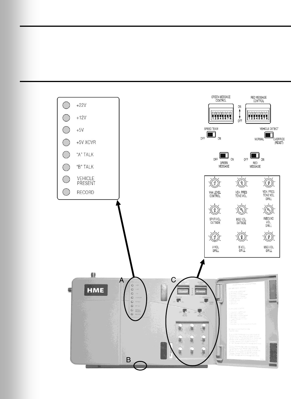
1.1.1 External Features
Figure 2. Base station with front door open

3
Front – (See A on Figure 2.)
The top four power supply lights are on when the base station has AC power.
“A” TALK light is on during channel-A transmission.
“B” TALK light is on during channel-B transmission.
VEHICLE PRESENT light is on when a vehicle is present in the drive-thru lane or
when the system is in vehicle-detect override.
RECORD light is ON RED when the base station is ready to record a red message
for the message repeater, and BLINKING RED while a red message is being recorded.
It is ON GREEN when the base station is ready to record a green message for the
message repeater, and BLINKING GREEN while a green message is being recorded.
Bottom – (See B on Figure 2.)
PUSH FOR RECORD MODE button must be pushed IN AND RELEASED ONCE to
prepare the base station to record a red message for the message repeater, or
pushed IN AND RELEASED TWICE to record a green message.
Behind Front Door – (See C on Figure 2.)
GREEN MESSAGE CONTROL and RED MESSAGE CONTROL switches must be in
the ON position to use the message repeater, OFF when the message repeater is not
being used. Instructions are given inside the front door.
SPEED TEAM switch must be in the ON position for speed-team operation, OFF for
normal drive-thru operation.
VEHICLE DETECTOR switch must be in the OVERRIDE position to disable the
vehicle detector. To reset the vehicle detector, switch to OVERRIDE for 5 seconds,
then switch back to NORMAL for normal vehicle detection. If the switch is left in the
OVERRIDE position, the outside microphone will remain on.
DIP switches at the top are used to control messages going to the outside speaker, grill
speaker or COMMUNICATOR®s. DIP switch settings are shown inside the front door.
Nine level controls are used to set the following levels:
VAA LEVEL CONTROL adjusts the volume level at which one’s own voice is heard
in the headset while speaking into the microphone. Turn clockwise to lower the voice
level in the headset earpiece. Turn counterclockwise to raise the voice level.
VEH. PRES TONE VOL. adjusts the vehicle-present tone volume in the headset.
VEH. PRES. TONE VOL. GRILL adjusts the volume of the vehicle present tone
played through the grill speaker.
SPKR VOL. OUTSIDE adjusts the outside speaker volume.
MSG VOL. OUTSIDE adjusts the volume of the outgoing message-repeater message
to the customer at the speaker post or menu board.
INBOUND VOL GRILL adjusts the volume of the inbound audio from the outside
microphone played through the grill speaker.
A VOL. GRILL adjusts the volume of channel A communication, from
Communicator operators, played through the grill speaker.
B VOL. GRILL adjusts the volume of channel B communication, from
Communicator operators, played through the grill speaker.
MSG VOL. GRILL adjusts the volume of the recorded message played through the
grill speaker.
4
1.2 COMMUNICATOR®s
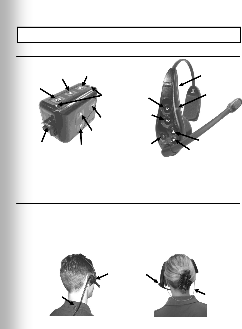
1.2.1 Features and Controls
1.2.2 How to Wear the COMMUNICATOR®
Wear the headset with the microphone on your right or left side next to your mouth.
Adjust the headband and microphone boom as needed.
If you are using a belt-pac with headset, clip the belt-pac to your belt or waistband
on either your right or left side. Clip the clothing clips on the headset cable to the
back of your shirt and collar.
If you are using an Odyssey IQ headset, put the headset on your head with the
headset band behind your neck.
Figure 3. Communicator controls
Figure 4. Correct wearing of the headset
IMPORTANT! Before doing anything else, set up the battery charger and charge the
Communicator batteries according to the instructions in section 2.2 on pages 9 and 10.
Belt-pac Communicator
Odyssey IQ all-in-one
headset Communicator
Belt-pac headset
Odyssey IQ headset
Headset band
Hold microphone
boom here to adjust
microphone position
Clothing clip
Channel “A1”
button
Channel “B”
button
Channel “A2”
button
Volume-up
button
Volume-down
button
Power
button
Power
light
Channel “A1”
button
Channel “B”
button
Power
button
Volume-down
button
Channel “A2”
button
Headset cable
connector socket
Volume-up
button
Power
lights

5
1.2.3 How to Use the COMMUNICATOR® Controls
The Communicator control buttons have a snap action. They will activate when
pressed firmly. Use your fingertips, not your fingernails, to press the buttons.
Refer to Figure 3 on page 4.
Power On/Off:
Power On Press and release the PWR (power) button. A voice message in the
earpiece will say “belt-pac #, battery full/half/low” and the red power lights next to
the A1 and A2 buttons on the belt-pac will go on. After a short time, one light will
go off and the other will change to green. A voice message will then say “Lane 1 (or 2)
ready.” The green light indicates the Communicator is ready to use. In dual-lane
operations, a green light next to A1 indicates ready on Lane 1 and a green light next
to A2 indicates ready on Lane 2.
Power Off Press and hold the PWR button for about two seconds. A voice
message in the earpiece will say “belt-pac off,” and the power lights will go off.
Volume Up/Down:
Volume Up Adjustment — Press and release the volume-up ▲ button. Each time
you press the button you will hear a higher pitch beep in the earpiece as the volume
increases. When you reach maximum volume, you will hear a high-pitched double
beep. If you press and hold the volume-up ▲ button, you will hear repeating beeps,
increasing in pitch until the volume reaches maximum. Then you will hear high-
pitched double beeps repeating until you release the volume-up ▲ button.
Volume Down Adjustment — Press and release the volume-down ▼ button.
Each time you press the button you will hear a lower pitch beep in the earpiece as
the volume decreases. When you reach minimum volume, you will hear a low-
pitched double beep. If you press and hold the volume-down ▼ button, you will
hear repeating beeps, decreasing in pitch until the volume reaches minimum. Then
you will hear low-pitched double beeps repeating until you release the volume-down
▼ button.
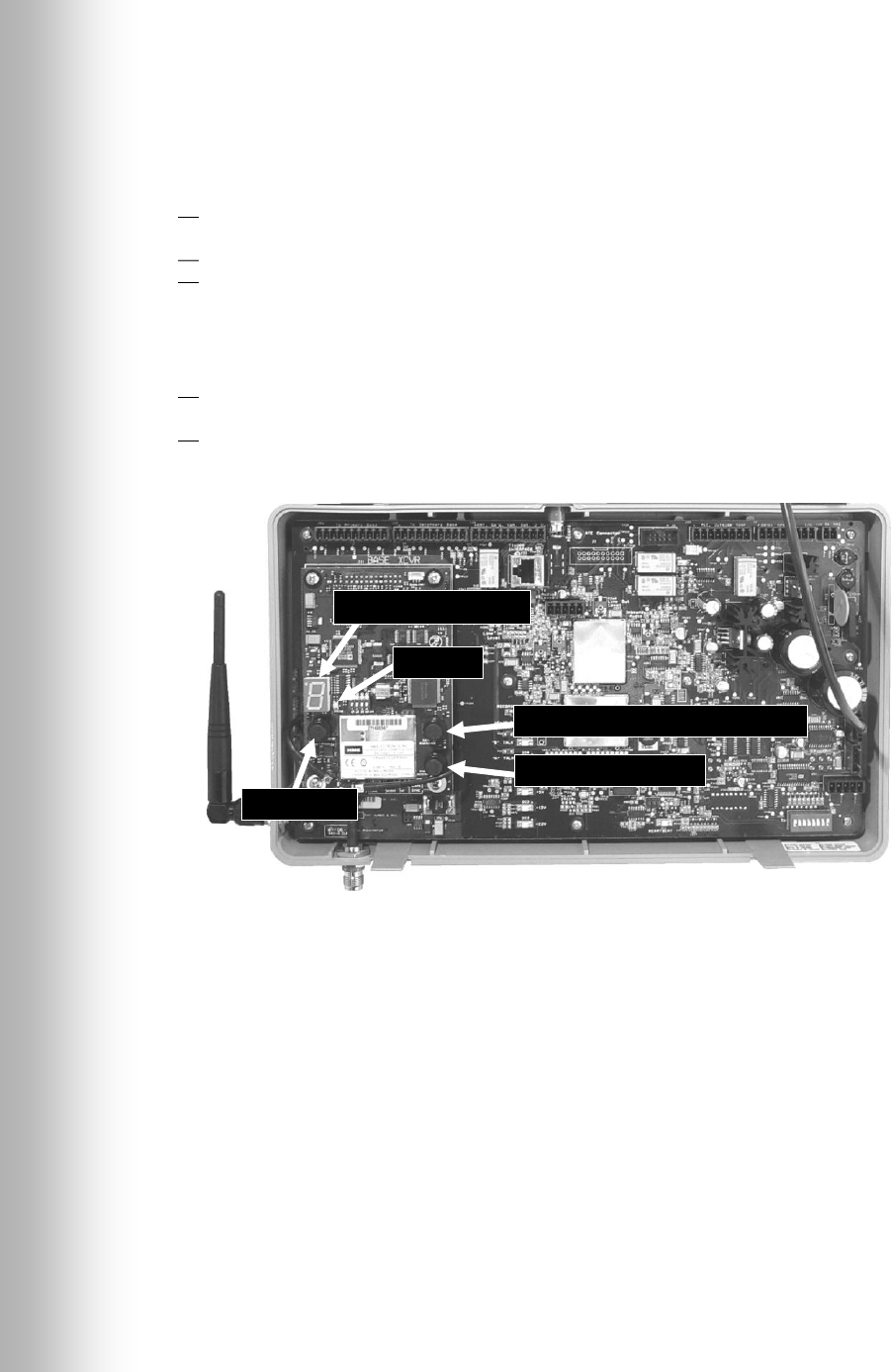
1.2.4 COMMUNICATOR® Registration
Before you operate the Wireless IQ system, you must register each Communicator for
use with the base station. The base station will then recognize all Communicators
registered to it when their power is on, and will be able to tell the difference between
them and other electronic equipment operating on similar frequencies.
Note: In tandem or dual-lane systems there are two base stations, a primary and a
secondary. Communicators must be registered to the primary base station.
A maximum of 15 Communicators can be registered. If a Communicator is replaced,
you must register the new one before you use it. When a Communicator is replaced,
the old one remains in memory. If the maximum number of 15 (in memory) is
exceeded, the Communicator ID display in the base station will show “F” for full. See
Figure 5. If this happens, you must clear all current registrations and re-register all
active Communicators. To clear all current registrations, press the “CLEAR ALL
REGISTRATION” button and the “RESET” button at the same time. Refer to Figure
5 on page 6. Continue holding the “CLEAR ALL REGISTRATION” button after
releasing the “RESET” button, until the clear code “c” (lower case) appears on the
Communicator ID display. Register all active Communicators the same way, one
at a time.
6
Register each COMMUNICATOR® as follows:
Note: Communicators must be within 6 feet (1.83 meters) of the base station while
being registered.
Be certain all Communicators to be registered are turned off and the base station is
plugged in and its power is on. Other Communicators can be on or off. See Figure 30
for base station power adapter/supply connections to the J29 connector.
Open the base station and locate the items shown in Figure 5.
If no Communicators are on, the status light will begin blinking red. If any
Communicators are on, the status light will be on steady green.
Press and release the START REGISTRATION button.
The Communicator ID display will show a small “o” for open, and the status light
will blink green.
Press and hold the B button on the Communicator while pressing and releasing its
PWR (power) button to turn the Communicator on, and release the B button. This
will cause the Communicator to enter the registration mode.
The status light in the base station will be blinking green and the Communicator
ID display will continue to show a small “o” for open.
The power lights next to the A1 and A2 buttons on the Communicator will be
blinking red then will change to green.
When the registration is successfully completed:
The green status light in the base station will be on steady and the Communicator
ID display will show the ID number assigned to this Communicator. ID numbers
are assigned sequentially as 0 thru 9, A, b, C, d and E.
One of the power lights on the Communicator will remain on steady green.
If the registration failed:
A message in the headset will say “Beltpac/Headset #, Battery Low/Half/Full,
Registration …” The Communicator power light/s will blink red and after a delay of
up to 1.5 minutes you will hear “Registration failed.”
Note the condition of the STATUS light in the base station. Press the RESET button.
The STATUS light may blink and change colors. When the STATUS light returns to
its previous condition, press the START REGISTRATION button and repeat the
registration procedure.
If the registration fails again:
In the USA, call HME Customer Support at 1-800-848-4468.
Outside the USA, call your local HME representative for assistance.
Figure 5. Registration buttons and indicators
Communicator ID display
Status light
RESET button
CLEAR ALL REGISTRATION button
REGISTRATION button
7
Battery-release
latch
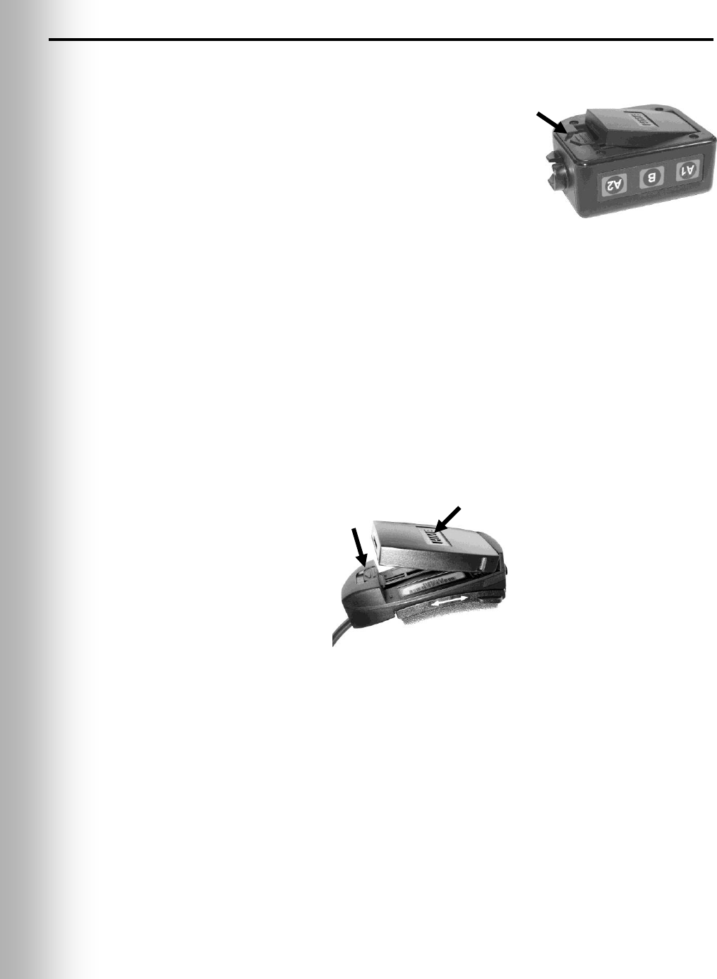
1.2.5 Battery Removal and Replacement
COM6000BP Belt-pac Batteries —
To change batteries:
If a battery is weak when the COMMUNICATOR®
power is turned on, a voice in the earpiece will
say “Battery low.” If a battery becomes weak
during operation, a voice in the earpiece will say
“Change battery.” When this happens, take the
Communicator out of its pouch and slide the
battery-release latch in the direction of the
arrow. Pull up on the end of the battery near
the latch and lift it out of the Communicator, or
turn the Communicator over and catch the battery
in your hand.
To replace batteries:
Place the end of the battery with the metal contacts into the Communicator, in the
same position as the battery you removed. Press the top of the battery carefully
down into the Communicator until it snaps in place.
Odyssey IQ Headset Batteries —
To change batteries:
When a battery becomes weak, a voice in the Headset will say “Change battery.”
When this happens, remove the battery from the Headset by carefully sliding the
battery-release latch and lifting the battery out.
To replace batteries:
When replacing a battery in the Headset, place the end of the battery with the metal
contacts into the battery holder on the Headset, in the same position as the battery
you removed. Press the top of the battery carefully into the battery holder until it
snaps in place under the battery-release latch.
Recharge batteries according to the instructions on pages 9 and 10.
Figure 6.
Belt-pac battery-release latch
Battery-release
latch
Battery
Figure 7. Headset battery-release latch
8
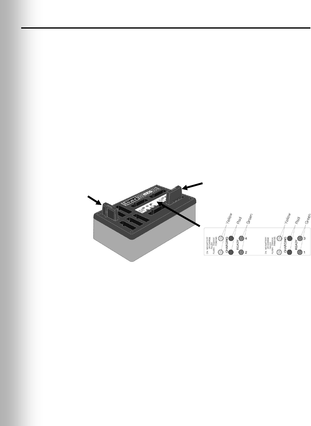
1.3 Battery Charger
The battery charger has charging ports to charge up to four batteries at the same
time. Charging time is about 2.5 hours. Six battery storage ports are provided to
store up to six fully charged batteries.
Battery Status Lights:
A yellow light stays on steady next to each charging port while the port is empty.
Insert a battery in one of the four charging ports until it clicks in place.
If a yellow light is on steady next to a battery in a charging port, it means CHARGE
FAILED. Follow the diagnostic instructions on the side of the battery charger.
If a yellow light is flashing next to a battery in a charging port, it indicates CHARGE
PENDING, which means the battery is too hot. Lower the room temperature or move
the charger to a cooler area.
A red CHARGING light will stay on next to a battery in a charging port while the
battery is charging.
A green READY light will go on next to a battery in a charging port when the battery
is fully charged.
Store fully charged batteries in the storage ports.
Figure 8. Batteries in charger
Battery in
storage port
Battery in
charging port
9
2. PREPARATION FOR INSTALLATION
About 3 hours are required for Wireless IQ installation.
Before you begin, coordinate the time of installation with the store owner/manager
to minimize disruption of business.
Be certain electrical power is available.
Be certain some type of compatible vehicle detector loop or other vehicle detector
system has already been installed in the drive-thru lane(s).
2.1 Tools Required
Phillips (cross-point) screwdriver, size #2 wire cutter/stripper
standard (slotted) screwdriver, inch (3.2 mm) soldering iron
power drill and drill-bit set rosin-core solder
fish tape, 100 feet (30 meters) electrical tape
2.2 Battery Charger Setup and Battery Charging
Set up the battery charger and charge the COMMUNICATOR® batteries as follows.
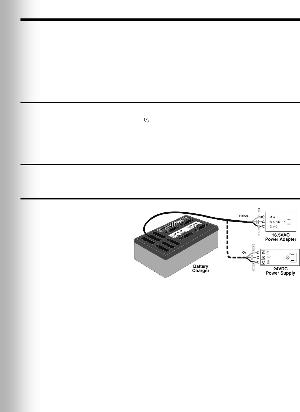
2.2.1 Battery Charger Setup for Use In the United States
Connect the battery
charger cable to the
16.5VAC power adapter
or 24VDC power supply
as shown in Figure 9.
Plug the adapter into an
AC electrical outlet. The
red lights on the charger
will come on and go off,
then the yellow lights will
come on and stay on.
Figure 9. Battery charger power connection

10
2.2.2 Battery Charger Setup for Use Outside the United States
To use the battery charger outside the United States, in countries requiring a 230
Volt AC adapter, modify the 230VAC adapter as follows. The 24VDC power supply
will work with an input AC voltage of 100-240VAC.
Connect an electrical plug to the wires on the power cable according to color codes
(Brown = live, Blue = neutral, Green with yellow stripes = ground).
Plug the other end of the power cable into the AC adapter.
Cut the connector off the AC adapter cable. Cut the spade lugs off the brown and
blue wires of the battery charger cable and cut the green/yellow ground wire as
short as possible. No ground wire will be used. Strip enough of the insulation from
the wires of both cables so they can be spliced. Splice the AC adapter cable wires to
the brown and blue “AC” wires of the battery charger cable. Cover the splice with
electrical tape or shrink tubing.
Plug the electrical plug into an AC electrical outlet. The red lights will come on and
go off, then the yellow lights will come on and stay on.
2.2.3 Battery Charging
Insert up to four COMMUNICATOR® batteries into the charging ports to be charged
while you are installing the other equipment. When they are fully charged, install
them in the Communicators. Battery charging time is about 2 hours.
CAUTION: Do not remove batteries from the charger until the green READY
light is lit, or the charger will reset and the charge cycle will begin again.
Figure 10. 230VAC adapter wiring for battery charger

11
2.3 Interference Prevention
CAUTION: Interference may occur if the audio system is not properly installed.
The following types of interference could occur if precautions are not taken during
installation. Read this section carefully before proceeding.
2.3.1 Radio Frequency (RF) Interference
Finding the cause of RF interference is difficult and time-consuming. The following
precautions will help you avoid the most common RF interference problems.
Find the best base station and antenna locations before mounting them.
Solder all joints (including crimp joints) at the speaker location. This is very
important in damp climates
Be certain all connections are tight.
Avoid leaving unshielded wire anywhere in the audio system.
Ground the shield of the outgoing speaker cable. In severe cases of interference,
grounding the shield at the speaker may help.
AM and FM interference may cause similar problems but require different corrective
action. AM interference may increase or decrease at certain times of day, since AM
transmitter power must be reduced in some areas between 5 and 7 PM.
Note the following symptoms carefully to determine the possible cause of
interference. Call HME at 1-800-848-4468 if you need help.
AM Interference:
Static or hum may be heard in the headset when the system is active. The AM
interference can enter the system through the cables connecting the outside
speaker/microphone to the base station. To block the AM signal, first find out if
there is an AM station in the area, and find out its operating frequency and
transmitter output power. You can then modify the equipment with a network of
inductors and capacitors that will trap the AM signal where it enters the system.
Static, hum and/or voice may be heard in the headset when the system is active or
when transmitting in either channel A or B. The interference can enter the system
at three different locations: the outside speaker cables, the COMMUNICATOR®
receiver and the base station transmitter. The AM station frequency may completely
suppress or overpower the audio system’s transmitter signal, depending on the
operating frequency, transmitter tower location and output power of the AM radio
station. You may need to move the base station.
FM Interference:
FM interference may cause cracks, pops and other noises to be heard in the headset
when the Communicator is transmitting on either channel A or B, or when the
system is active.

12
2.3.2 Electrical Interference
Electrical faults in appliances and other electrical equipment can cause interference
such as static, hum, crackling, buzzing and zip sounds in the headset when the
system is active. Interference caused by electrical faults in lighting systems might
not be noticed immediately, since most lighting systems are controlled by a timer or
light-sensing device.
Faulty Wiring or Components:
Faulty components or electrical wiring in menu boards or speaker posts can cause
symptoms identical to those caused by AM interference. Remove power to the menu
board or speaker post at the circuit breaker until the electrical system can be repaired.
Improper Earth Grounds:
Improper earth grounds in the building can cause random buzzing and zip sounds in
the headset when operating in either channel A or B. Placing a surge protector between
the base station AC adapter and the electrical outlet can eliminate the problem.
In the event of an electrical power outage —
such as from a lightning storm or power generator failure, if you experience problems with your
HME equipment after the electricity comes on again, unplug the equipment and wait 15 seconds,
then plug it back in.
13
3. EQUIPMENT INSTALLATION
These instructions are for installation of standard Wireless IQ equipment and most
commonly used optional equipment. Specific instructions may also be enclosed
with optional equipment.
IMPORTANT! If you haven’t already done so, before proceeding with the installation,
plug the battery charger into an AC electrical outlet and place all COMMUNICATOR®
batteries into it for charging while the other equipment is being installed.
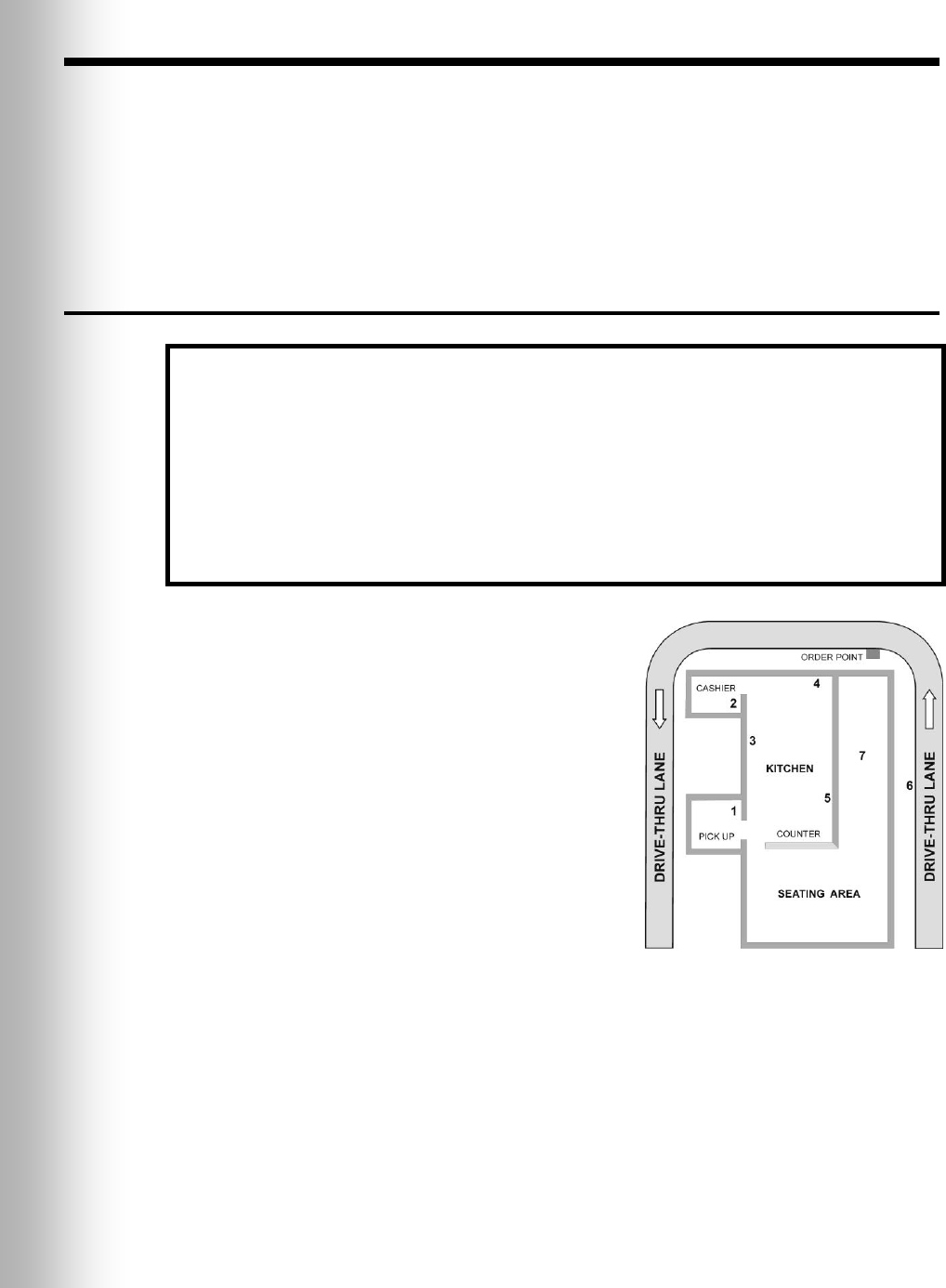
3.1 Base Station Installation
A typical drive thru QSR building is set up as
shown in Figure 11. The numbers in Figure 11
refer to the location numbers in the following
instructions. This drawing is similar to most store
layouts. The base station is typically mounted at
location #1. This is also where old equipment is
usually found. The order taker is usually at
location #2 in a high volume store. The order
taker Communicator signal from location #2 must
penetrate two walls to reach the base at location
#1. Communicator signals from the kitchen must
only penetrate one wall to reach the base at
location #1. If there are large pieces of equipment
in the kitchen or speed team operation is needed
outside at location #6, location #1 may be a poor
choice for mounting the base. For speed team
operations, the signal would have to penetrate
three walls and get by the kitchen equipment to
reach the base at location #1. Coverage in the store around location #7 and outside
at location #6 may be poor. Don’t forget to check for a basement. Communicator
signals from basements may not reach the base at location #1.
If outside coverage is not needed, mounting the base at locations #3, #4 or #5 is best.
Communicator signals from most work areas would thereby require no wall penetration.
Other work and seating areas may require signals to penetrate one wall. In this case,
the remote antenna kit can be used. The antenna may not need to be mounted very far
from the base station unless a large piece of equipment causes a dead spot.
The Wireless IQ base uses two antennas to avoid multi-path dropouts. Both
antennas transmit and receive signals. The antenna coverage area can be improved
by mounting one antenna away from the base. The base will select the antenna that
gives the best signal to a particular COMMUNICATOR® location.
Things to consider before and during base station installation
The base station should be located where, if you stand with your back to the wall, you
can see most of the work area where the Communicators will be used.
The number of walls between the base station and where the Communicators will be
used should be minimized.
Sheets of stainless steel on the walls may shield or reflect radio signals.
Outside coverage may be needed for Speed Team operation.
Large windows will allow the signal to pass through and can improve outside coverage.
The antenna coverage area can be extended with the Remote Antenna Kit.
If a system is being replaced, it may not be desirable to use the same mounting location
for the base station as used before, but it may be required it in some cases.
Figure 11. Typical drive-thru
store layout
14
If outside coverage is required for speed team coverage, mount the base as close as
possible to the wall that faces the desired coverage area. In this case, mounting the
base at location #5 to cover location #6 will minimize wall penetrations. Stores with a
large window near the base will have better outside coverage if the base is facing the
windows. If there are large windows along the wall next to location #6 outside
coverage will be enhanced. Also consider in-store coverage. If the base is located in
the best location for inside and outside coverage, but the coverage outside is still
spotty then the antenna extension cable needs to be run outside the store. In this
case, hanging the antenna under an eve next to the desired area will cover that side of
the store very well. Another approach is to go up through the roof and have the
antenna overlook the desired side area. This approach overcomes obstacles, like
walls, that may shadow the signal when the antenna is at a lower height.
Discuss the location of the base station with the store owner or manager. It should
be mounted less than 10 feet (3 meters) from an available electrical outlet, and away
from grease and large metal objects. Also, the base transmitter antenna(s) must be
installed where they will be at least 7.87 inches (20 cm) from all persons, and will not
be near any other antenna or transmitter. The remote antenna kit should be used to
extend the coverage area if needed. See section 3.1.3.
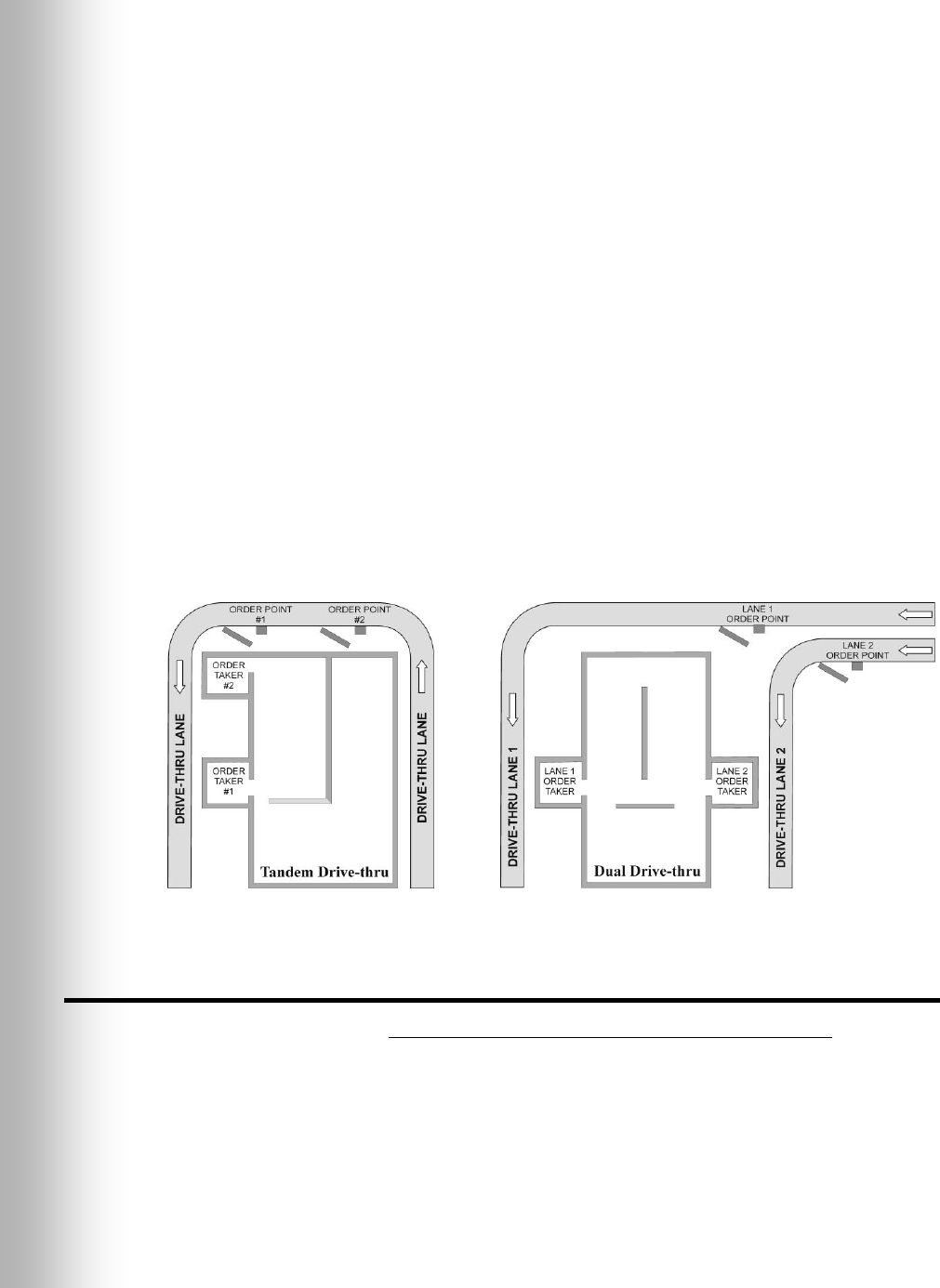
Tandem or Dual Drive-Thru Base Stations
For tandem or dual drive-thrus, two base stations (primary and secondary) will be
installed. They must not be more than 20 feet (6 meters) apart. Cables must be
pulled and routed to connect the primary base station to the secondary base station
as shown in the wiring diagrams on pages 43 – 50. A vehicle detector and an outside
speaker and microphone will be installed for each order point, and cables pulled as
described in sections 3.2 and 3.3.
3.1.1 Walk Test for Best Transmission/Reception
You must do a walk test before permanently mounting the base station, with the
base station at various locations until the best possible transmission/reception is
found. Check transmission and reception around the area where the
COMMUNICATOR®s will be used, with two people using Communicators (with fully
charged batteries) pressing button B to communicate with each other. Also, walk
past the menu board to test reception when using speed-team operation.
If you need to extend the antenna coverage area, remove power from the base
station and install the Remote Antenna Kit as described in section 3.1.3, but do not
permanently mount the antenna. Return power to the base station and place the
antenna in the area where improved performance is needed. Repeat the walk test as
described above, moving the antenna around the area while communicating to
determine where the antenna improves transmission and reception most.
Figure 12. Typical tandem and dual drive-thru layouts
15
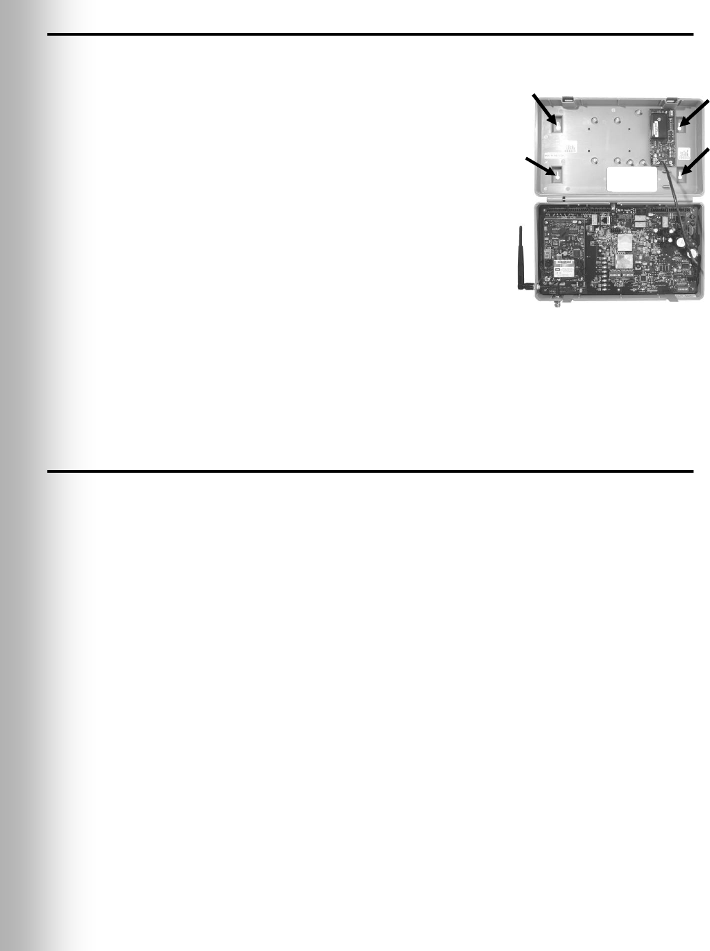
3.1.2 Mount Base Station on Wall
When you have found the best location for transmission and reception, unplug the
AC power and mount the base station and antenna as follows.
Hold the base station against the wall at the desired
mounting location, with its door open, and mark the
wall through the four screw holes on the back of the
cabinet, shown in Figure 13.
Set the base station down and drill four 3/16 inch
(4.76mm) holes in the wall at the marked spots.
Insert the enclosed #6 screw anchors into the holes.
Screw the four enclosed screws into the anchors, leaving
the screw heads 1/8 inch (3.2 mm) away from the wall.
Mount the base station on the wall by placing the four
screw holes in the back of the base station over the four
screws, and sliding the base station downward.
Connect the base station power adapter cable to the
adapter as you did for the battery charger, as shown in
Figure 9, page 9. For use outside the United States, see
230VAC adapter connections shown in Figure 10, page 10.
Connect the two wires at the other end of the cable to J16 on the top-left of the
audio circuit board in the base station.
Plug the adapter into the electrical outlet nearest the base station.
3.1.3 Install Remote Antenna Kit (if needed)
The remote antenna kit allows one of the antennas to be mounted up to 30 feet
(9.14 meters) from the base station for improved coverage. With the extension cable
and mounting bracket, an antenna can be mounted inside a window or outside to
extend coverage for speed team operation. Install the remote antenna kit as follows.
Lay out the enclosed 30 foot (9.14 meter) antenna cable, with its female connector
near the base station and its male connector at the proposed area where the
antenna will be mounted. Bend and align the cable to the desired position.
Remove electrical power from the base station.
Remove (unscrew) the antenna from the top of the base station.
Screw the female antenna cable connector onto the base station antenna connector
where the antenna was removed.
Note: To minimize stress on the connector, bend the cable as required to line it up
with the base station antenna connector before connecting it.
Screw the antenna onto the male connector at the other end of the antenna cable.
Hold the enclosed antenna mounting bracket against the wall at the desired
mounting location and mark the wall through the two screw holes in the bracket.
It may be necessary to mount the antenna high enough to avoid a safety hazard or
possible damage to the antenna.
Remove the bracket from the wall and drill two 3/16 inch (4.76mm) holes in the wall
at the marked spots.
Insert the enclosed screw anchors into the holes.
Place the enclosed screws through the holes in the bracket and screw them into the
two screw anchors to secure the bracket to the wall.
Figure 13. Open base station
showing four screw holes
16
Remove the antenna from the antenna cable. DO NOT remove the antenna cable
from the base station.
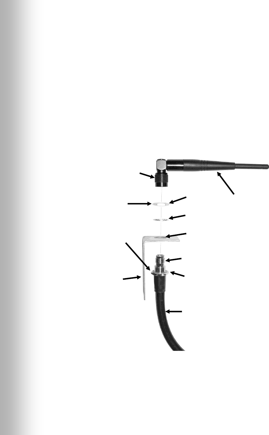
Unscrew the hexagonal nut from the antenna cable connector.
Insert the antenna cable connector through the hole in the mounting bracket as
shown in Figure 14, and screw the hexagonal nut onto the connector to secure it in
place on the bracket.
Note: To minimize stress on the bracket, bend the cable to line it up with the bracket
before connecting it.
Replace the antenna on the cable connector mounted on the wall.
Note: The best transmission and reception may be achieved with the antenna
perpendicular to the wall. However, if it is a safety hazard or is likely to be bumped
and damaged in that position, it may be necessary for the antenna to be parallel to
the wall.
Return electrical power to the base station and resume normal operation.
CAUTION:
Use two wrenches
when tightening
nuts, to prevent
twisting and
damaging cable.
Hexagonal
nut
Lock
washer
Hole in
bracket
Male
antenna cable
connector
Hexagonal
nut
Antenna cable
Antenna
NOTE: The wall bracket
can be mounted as shown,
or in the reversed position,
with the hole for mounting
the antenna at the bottom.
Wall bracket
Antenna
connector
(screw type)
Figure 14. Remote antenna mounting on wall bracket

17
3.2 Cable Pulling
CAUTION: If you do not use the HME audio cable, be sure the speaker/microphone
wires you use are a twisted pair. For full-duplex installations, the speakers
and microphones must use separate cables or audio feedback will occur.
Never run high-voltage cables in the same conduit with audio or loop cables.
The recommended HME audio cable has four color-coded, insulated wires and a
bare shield (drain) wire. It can be used to connect any component to the base
station. Pull the cables (two for full-duplex, one for half-duplex) through the
conduit from the speaker post or menu board into the building as follows.
For dual drive-thru installations, repeat the following steps to route shielded cable
from inside the building to the speaker post or menu board in each lane.
For tandem drive-thru installations, repeat the following steps to route shielded
cable from inside the building to the speaker post or menu board at each order point.
Run fish tape from inside the building, through the conduit to the speaker post or
menu board.
Go outside. If you are pulling more than one cable, mark the cables and spools
for identification. Fasten each cable to the fish tape where it comes out of the
conduit, and go back inside the building.
Pull the fish tape and cable through the conduit into the building. Disconnect the
cable from the fish tape and pull enough of it in to reach the base station.
Go outside again and route the cable from the outside conduit to the speaker and
microphone units in the speaker post or menu board.
Cut the cable, leaving about 3 feet (915 mm) of slack. If more than one cable have
been pulled, mark the ends of the cables again for identification.
Remove about 2 inches (50 mm) of the outer insulation from the end of each cable.
Strip about ½ inch (12 mm) of insulation from each of the four wires in the cable.
Route all the cables together to the base station, through walls and over ceiling
panels if possible. Cut off any slack cable so no coils of excess cable are left in the
ceiling or elsewhere.
3.3 Outside Speaker and Microphone Installation
and Cable Connections
This section describes standard, full-duplex installations, using a DM3 microphone
and SP2500LP Low-Profile Speaker. Installation requirements may vary. In dual-
lane or tandem systems, speakers and microphones must be installed for each lane
or order point. Refer to the wiring diagrams on pages 43 – 50.
Note: For half-duplex installations, the SP2000A Speaker/Microphone Unit is used.
See Section 3.4, page 20 for installation of the SP2000A.
In full-duplex systems the standard microphone and speaker provide the best
performance. However, in some cases the DM1 Microphone may be used. For DM1
installation, refer to the instructions enclosed with the unit. For either the DM1 or
DM3, refer to the appropriate wiring diagram on pages 43 – 50.
Mount the microphone first, against the speaker grill in the speaker post or menu
board. Positioned it where the customer will speak directly into it. The speaker can
then be installed anywhere around the microphone, as long as they are at least
2 feet (610 mm) apart, center-to-center, to avoid audio feedback.
Note: Try the system with the speaker at various locations around the microphone
before permanently mounting it. If feedback occurs, move around until the
feedback disappears. If possible, park a vehicle in front of the outside microphone
to simulate echo conditions that may also cause feedback.
18
3.3.1 Microphone Installation
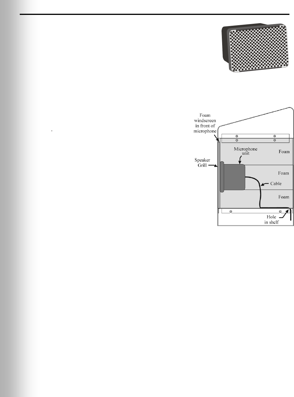
Typical microphone installation involves mounting the
unit with the enclosed foam pieces, inside the upper
compartment of the speaker post. The foam will fit
many types of speaker posts and menu boards. If the
microphone must be mounted in a small area, compress
the foam when installing it and closing the speaker post
or menu board. In larger areas, additional foam (not
supplied) must be added. To install the microphone in a
typical speaker post, follow the instructions below and
refer to Figure 16. Installation in a menu board will
be similar, within the menu-board speaker compartment.
Open the speaker post and remove any
existing equipment, foam or debris. If there
Speaker
Grill
Foam
windscreen
in front of
microphone
Microphone
unit
Cable
Hole
in shelf
Foam
Foam
Foam
is an existing microphone, remove it and
disconnect the microphone cable from it.
Splice the wires of the audio cable (new or
existing) to the wires of the cable extending
from the microphone unit, according to the
audio system wiring diagram.
Place the enclosed foam windscreen
against the inside of the metal speaker grill.
Place the front of the microphone unit flush
against the foam windscreen, centered on the
speaker grill.
For the best performance, mount the
microphone flush and tight against the foam
windscreen, behind the speaker grill. Pack the
remaining pieces of foam around the top, bottom
and back of the microphone unit, so it will be
held in place against the speaker grill when the
compartment is closed. If required, add extra
foam (not supplied) on the sides of the
microphone to fill the enclosure.
IMPORTANT! In the speaker post or menu board, fill all the holes and openings in
the panel that separates the speaker and microphone, with insulating foam sealant
(“Great Stuff” expanding polyurethane foam or equivalent, available at home
improvement stores).
CAUTION: Do not use the foam sealant in a wet area, or allow it to come in
contact with water. See can for precautions and safety information.
Close the speaker post.
Figure 15. Microphone
Figure 16. Microphone unit and
foam inserts shown in typical
speaker post installation
19
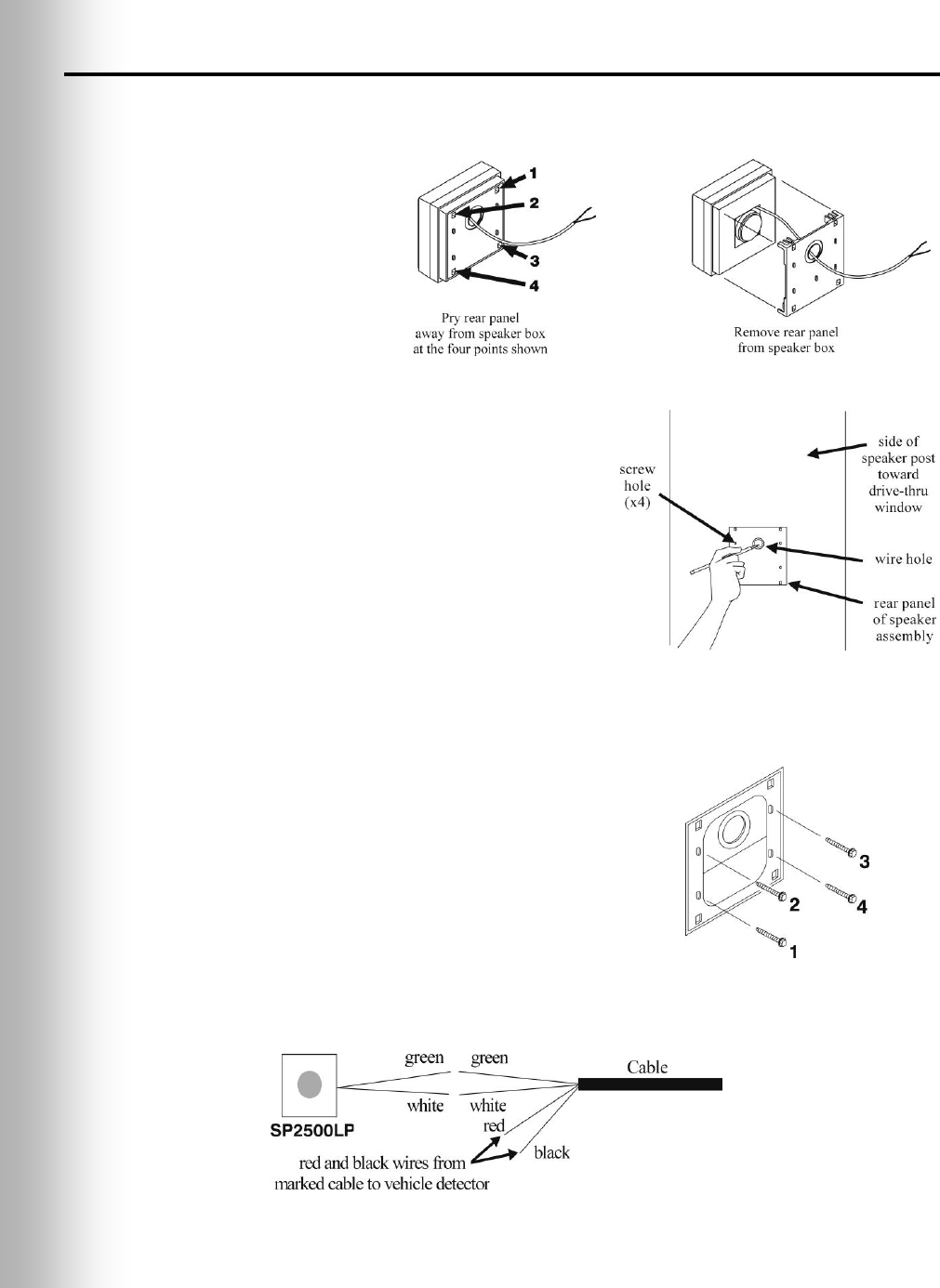
3.3.2 SP2500LP Low-Profile Speaker Installation
Use a flat-blade screwdriver, or similar tool, to open the SP2500LP speaker box by
prying the rear panel off the box at the four points shown in Figure 17, and remove it.
Note: Mount the speaker
inside the speaker post
or menu board if
possible. It must be
mounted at least 2 feet
(610 mm) from the
microphone,
center-to-center.
Hold the rear panel of the SP2500LP flat
against the surface of the speaker post or
menu board, at the desired mounting
location, as shown in Figure 18. Use a
pencil to mark the speaker post through the
wire hole in the panel. Remove the panel
and set it aside. Drill a ¼ inch (6 mm) wire
hole at the marked location.
Hold the rear panel against the surface, in
the same position as before, and screw the
four enclosed self-tapping screws through
the screw holes on the panel into the speaker
post or menu board as shown in Figure 19.
Route the cable from the back of the speaker
through the wire hole in the rear panel of the
speaker box, into the speaker post.
Close the box by pressing it against the rear panel.
SP2500LP Cable Connections:
Inside the speaker post or menu board,
connect the green and white wires of the
appropriate cable to the wires coming from the
speaker as shown in Figure 20. Do not connect
the drain wire. Solder the connection and
cover it with a crimp cap insulator.
IMPORTANT! For full-duplex systems, use
separate cables for speaker and microphone,
or feedback may occur.
3.4
Figure 17. Open the low-profile speaker
Figure 18. Mark speaker post or menu
board through wire hole in rear panel
of SP2500LP speaker assembly
Figure 19. Screw the self-tapping
screws through holes in rear panel
of SP2500LP speaker box
Figure 20. SP2500LP cable connections
20
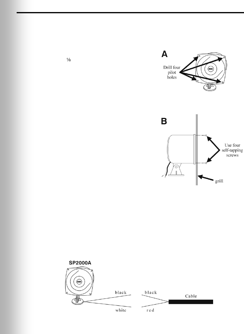
Optional SP2000A Speaker/Microphone Installation
Note: The installation described below is for typical mounting of the SP2000A directly
against the inside of the speaker grill. If it needs to be mounted at an angle, or at a
distance from the speaker grill, its base can be bolted to a horizontal surface.
Installation
Drill four inch (3.2 mm) pilot holes at the
spots shown on Figure 21 A, in the flange of
the SP2000A.
Find the enclosed SP2000A mounting template.
Hold the template centered against the outside
of the speaker grill on the speaker post or
menu board. With a pencil or other sharp
object, mark the speaker grill through the four
drill-hole targets on the template. Drill a 3/16
inch (4.8 mm) hole at each of the marked spots.
Hold the SP2000A flush against the inside of
the speaker grill, with the four pilot holes on
its flange directly over the four holes drilled
through the grill speaker. From the outside of
the speaker grill, drill the four enclosed self-
tapping screws through the drilled holes in the
speaker grill and through the SP2000A flange
at each pilot hole, as shown in Figure 21 B.
Cable Connections
CAUTION: Never run high-voltage cables in the same conduit with audio or
loop cables.
Connect the red wire from the appropriate cable to the white SP2000A wire, and the
black cable wire to the black SP2000A wire as shown in Figure 22. Do not connect
the drain wire.
Solder the connection and cover it with electrical tape. Solder all splices.
Figure 21. Installing the SP2000A
Figure 22. SP2000A cable connection

21
3.5 Optional External Vehicle Detector Installation
If an external type vehicle detector will be used, install it according to its own
installation instructions. Connect it to the base station according to the appropriate
wiring diagram on pages 43 – 50. Note that the connections are different for internal
and external vehicle detectors.
Route a cable from the external vehicle detector output to the J30 connector on the
audio board in the Wireless IQ base station.
Remove 4 inches (100 mm) of outer insulation from the end of the cable at the base
station, and strip about ¼ inch (6 mm) of insulation from each of the color coded
wires coming from the cables.
Connect the color-coded wires to connector J30, pins 3 and 5 for negative vehicle
detection according to the wiring diagrams on pages 43 – 50. Be certain the wires
are fully inserted into each connector plug to prevent shorting the wires.
3.6 Optional HME Vehicle Detector Board (VDB)
Installation
To install an HME VDB in the base station, follow the instructions below.
Note: In tandem systems, there will be a VDB in the primary base station for Order
Point #1, and a VDB in the secondary base station for Order Point #2.
Open the base station by pushing the latches on the front cover and VERY
CAREFULLY guiding the cover downward.
Carefully position the three holes in the VDB over the three plastic standoffs at the
upper right side, inside the base station, in the position shown on the respective
wiring diagram on pages 43 – 50. Press on the VDB until the tips of the three
standoffs snap through the holes in the board.
Connect the cable assembly enclosed with the VDB to the P1 connector on the
vehicle detector board, and the other end to the J6 connector near the upper, right
corner of the switcher board. If there is no switcher board, connect the cable
assembly to the P1 connector on the vehicle detector board, and the other end to the
J10 connector at the right end of the audio circuit board as shown on pages 43 – 50.
Route a cable from the underground loop to the TB1 terminal block on the Vehicle
Detector Board.
Close the cover on the base station, and lock it by pushing until it latches.
22
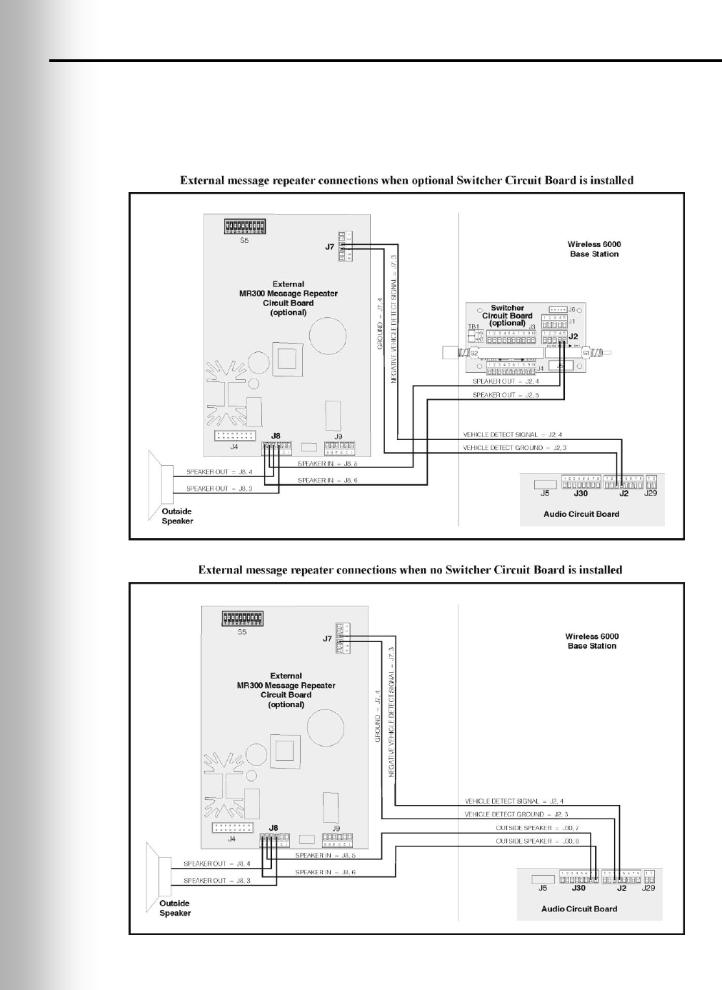
3.7 External Message Repeater Installation
If an external message repeater is used, it must be wired in series with the outside
speaker. It also requires a vehicle-present signal. Connect the message repeater
vehicle-present input to the isolated vehicle detector output on the Audio Circuit Board.
Note: No output detect will be generated if the base station power is removed.
Figure 23. External message repeater connections

23
4. EQUIPMENT SETUP
4.1 Internal Message Repeater Setup
Locate and set the “Red Message” and “Green Message” slide switches and the “Red
Message Control” and “Green Message Control” DIP switches on the front panel of
the base station. Refer to section 6.9 for “Red Message Control” and “Green
Message Control” switch functions and message recording instructions.
If a System 30 Timer is installed with the Wireless IQ, the timer alert output can
be used to trigger tones in the headset or a message to be played by the message
repeater. Set “Red Message Control” and/or “Green Message Control” #5 switch to
ON for an alert message, which will be heard through outside speakers and/or
headsets selected with the #2, 3 and 4 switches only in headsets, or OFF for an alert
tone to be heard only in headsets.
If Wireless IQ message repeater will not be triggered by an alert signal, set both
“Red Message Control” and “Green Message Control” #5 switches to OFF so the
message repeater input will be triggered only by vehicle detector signals.
4.2 Early Warning Setup
An extra vehicle detector can be used with the Wireless IQ to give a pre-warning
signal when a vehicle enters the drive-thru area. To set up a pre-warning signal, first
install the extra vehicle detector at the desired detection point then connect its cable.
If an external vehicle detector is used, connect its cable to connector J9,
positions 1 and 2 on the base station audio circuit board.
If an internal Vehicle Detector Board is used, connect P1 on the VDB to J15 on
the Audio Circuit Board. Also on the Audio Circuit Board, wire the J25 connector,
positions 8 and 9 to the J9 connector, positions 1 and 2 respectively.
4.3 Dual-Lane Setup
To set up the Wireless IQ system for dual-lane operation, place K1 DIP switch #1 on
the base station transceiver board in the ON position, then press the “Reset” button.
Refer to Figure 26 on page 35 and Figure 28 on page 37.
Set the “Green Message Control” DIP switch #8 to the ON position in the Secondary
Base only. The Primary Base must be wired to Lane 1, the Secondary Base to Lane 2.
4.4 Split-B Audio Setup
Split-B audio is used in dual-lane operations to limit audio transmission from Lane 1
COMMUNICATOR®s to be heard only by other Lane 1 Communicator operators, and
transmission from Lane 2 Communicators to be heard only by other Lane 2
Communicator operators. When the Split-B audio feature is not used, B audio
transmission from either lane is heard by all Communicator operators in both lanes.
To set up the Wireless IQ system for split-B audio operation, on the base station
transceiver board, place the K1 DIP switch #2 in the ON position, then press the
“Reset” button. Refer to Figure 26 on page 35 and Figure 28 on page 37.
4.5 Auto-Hands-Free Setup
Auto-Hands-Free operation is explained on pages 27 – 30. To set up the Wireless IQ
system for auto-hands-free operation, on the base station transceiver board, place
the K1 DIP switch #3 in the ON position, then press the “Reset” button.
Refer to Figure 26 on page 35 and Figure 28 on page 37.
24
5. SYSTEM FUNCTIONAL CHECK
ACTION
RESULT
Plug base station AC adapter into electrical
outlet.
System power is on. Base station POWER lights
are on. System is silent.
Go outside (or have someone else go outside) and follow the steps below.
Push COMMUNICATOR® button A and speak
into headset microphone.
Audio should be heard at outside speaker.
Release button A. Place vehicle detector reset
switch in OVERRIDE position. Tap on outside
microphone.
Vehicle present tone should be heard in headset
earpiece, followed by inbound audio. If this
does not happen, there is a wiring problem.
5.1 Noise Reduction Adjustment
When the ClearSound feature is turned on, it provides four levels of noise reduction.
It can be adjusted for the best balance of noise reduction and voice quality,
considering the store’s environment.
Locate the S13 switch near the center of the base station audio circuit board. Refer
to Figure 28 on page 37.
To turn the ClearSound noise reduction feature on, place the S13 switch position 2 ON.
ClearSound Noise Reduction Adjustments
18 dB reduction
(maximum)
13 dB reduction
9 dB reduction
6 dB reduction
(minimum)
S13 – 3
OFF
OFF
ON
ON
S13 – 4
OFF
ON
OFF
ON
S13 – 1 = VAA ON/OFF
S13 – 2 = ClearSound ON/OFF
Note: Factory default settings for S13-3 and S13-4 are shown in bold.

25
5.2 VAA (Voice Activated Attenuation) Adjustment
The VAA circuit reduces the level of the order taker’s outbound audio that is picked
up by the outside microphone and sent back to be heard in the order taker’s
headset. This is sometimes referred to as “external loop around” or “echo.”
Note: Misalignment of the VAA circuit can result in complaints of echo, feedback or
fluctuating inbound audio levels.
To activate the circuit, S13 switch #1 (See Figure 28, page 37) must be ON.
The factory default setting is ON.
VAA Threshold Level:
This is the volume level of the order taker’s voice required to activate the VAA
circuit. During normal operation, the inbound audio level should be reduced when
the order taker speaks to the customer, and should recover when the order taker
stops speaking. If speaking to the customer does not reduce the inbound level, turn
the VAA Level control on the front panel (See Figure 2, page 2) clockwise until the
inbound audio is reduced while speaking to the customer. If the inbound is
reduced anytime the outbound channel is open, regardless if the order taker is
speaking or not, turn the VAA Level control counterclockwise, so the inbound is
reduced only when the order taker is speaking.
VAA Attenuation Level:
This is the amount the inbound volume level is reduced when the order taker
speaks to the customer. The attenuation level is factory set at 15dB, and should
not require adjustment. If the order taker cannot hear the inbound audio at all
while speaking, the attenuation level may be adjusted. To increase the inbound
level while the order taker is speaking, turn R348 (See Figure 26, page 35)
counterclockwise. To reduce the inbound level while the order taker is speaking,
turn R348 clockwise. For assistance, call HME at 1-800-848-4468.

26
6. WIRELESS IQ OPERATION
The COM6000BP can be operated in Hands-Free (HF), Auto-Hands-Free (AHF) or
Push-To-Talk (PTT) modes. If your store does not have HF capability, the Wireless
IQ should be operated in the PTT mode, according to the instructions on the
following pages for single-lane or dual-lane stores.
A full-duplex system supports HF, AHF and PTT operation. Communication can be
transmitted and received at the same time, as in a normal telephone conversation.
In the AHF mode, transmission and reception are activated automatically when a
customer drives into the drive-thru lane. In the HF mode, transmission and
reception are activated by touching and releasing one of the A buttons on the
Communicator. In the PTT mode, one of the A buttons on the Communicator must
be held while the operator is talking to the customer. A half-duplex system only
supports the PTT mode. One of the A buttons on the Communicator must be held
while the operator speaks to the customer. The customer’s voice will not be heard
while the operator is transmitting.
In single lane operations, when a customer arrives in the drive-thru lane, you will
hear a single beep in the headset.
In dual-lane operations, when a customer arrives in the drive-thru lane you are
connected to you will hear a single beep in the headset; when a customer arrives in
the other lane, you will hear a double beep.
In dual-lane operation, if you are communicating with a customer in one lane when
another customer arrives in the other lane, you will hear a higher pitch double beep
in your headset. When the customer leaves the speaker post in the lane you are
connected to, the same high pitch double beep will repeat in your headset every four
seconds until you touch the A1 or A2 button to communicate with the customer in
the other lane.
Note: In dual-lane operations, if you have a Mode Switch and it is in the
“DEDICATED” position, you will only hear single beeps in your headset when
customers arrive in the lane you are operating.
6.1 Changing Languages
To change the language of the cues heard in the Communicator from English to
Spanish/French and back to English, with the Communicator power off, press and
hold the volume-down ▼ button and the A1 button while you press the power PWR
button. The language of the cues heard in the headset earpiece will change when
the power goes on.
6.2 Obtaining COMMUNICATOR® Status
To obtain Communicator status, with the Communicator power off, press and hold
the volume-down ▼ button and the A2 button while you press the power PWR button.
You will hear the status message in the headset earpiece when the power goes on.

27
6.3 Single-Lane Operation
(one base station for one speaker post in one lane)
Hands-Free (HF) Mode:
With the power off, press and hold the volume-up ▲ and B buttons while you press
and release the PWR button to turn the power on in the HF mode. The
COMMUNICATOR® will remember this setting.
As a customer enters the drive-thru lane, you will hear an alert tone (single beep) in
your headset, and you will be able to hear the customer at the speaker post or
menu board.
Use the volume-up ▲ and down ▼ buttons to adjust the customer’s voice level in
your headset if necessary.
Touch and release the A1 or A2 button to speak and listen to the customer.
Touch and release the A1, A2 or B button to end communication with the customer.
Touch and release the A1 or A2 button if you want to speak to the customer again.
If a customer drives away from the speaker post or menu board, the Communicator
will stop transmitting.
Auto Hands-Free (AHF) Mode:
Note: Only one Communicator operator at a time can use the auto hands-free feature.
If a Communicator is turned off while in the AHF mode, it will automatically be reset
to its previous operating mode.
With the power off, press and hold the volume-up ▲ and A1 buttons while you press
and release the PWR button to turn the power on in the AHF mode.
As a customer enters the drive-thru lane, you will hear an alert tone (single beep) in
your headset, and you will be able to hear the customer at the speaker post or
menu board.
Use the volume-up ▲ and down ▼ buttons to adjust the customer’s voice level in
your headset if necessary.
Speak and listen to the customer without pressing any buttons.
Touch and release the A1, A2 or B button to end communication with the customer.
Touch and release the A1 or A2 button if you want to speak to the customer again.
If a customer drives away from the speaker post or menu board, the Communicator
will stop transmitting.
Push-To-Talk (PTT) Mode:
With the power off, press and hold the volume-down ▼ and B buttons while you
press and release the PWR button to turn the power on in the PTT mode. The
Communicator will remember this setting.
As a customer enters the drive-thru lane, you will hear an alert tone (single beep) in
your headset, and you will be able to hear the customer at the speaker post or
menu board.
Use the volume-up ▲ and down ▼ buttons to adjust the customer’s voice level in
your headset if necessary.
Touch and hold the A1 or A2 button to speak to the customer. Release when
finished.

28
6.4 Dual-Lane Operation
(two base stations for two speaker posts in two lanes)
Hands-Free (HF) Mode:
With the COMMUNICATOR® power off, press and hold the volume-up ▲ and B
buttons while you press and release the PWR button to turn the power on in the HF
mode. The Communicator will remember this setting.
As a customer enters a drive-thru lane, you will hear an alert tone in your headset
(single beep for Lane 1, double beep for Lane 2), and you will be able to hear the
customer at the speaker post or menu board if that lane is selected.
Use the volume-up ▲ and down ▼ buttons to adjust the customer’s voice level in
your headset if necessary.
Touch and release the A1 button for Lane 1 or A2 for Lane 2, to speak and listen to
the customer.
Touch and release the A1, A2 (depending on lane) or B button to end communication
with the customer.
Touch and release the A1 button for Lane 1 or A2 for Lane 2, to speak to the customer again.
To change lanes, touch and release the opposite A button.
If a customer drives away from the speaker post or menu board, the Communicator
will stop transmitting.
Auto Hands-Free (AHF) Mode:
Note: Only one Communicator operator at a time, in each lane, can use the AHF
feature. If an operator attempts to configure another Communicator, “System busy”
will be heard in his headset. Changing lanes is not possible in the AHF mode. If you
turn a Communicator off in the AHF mode, it will reset to its previous operating mode.
For Lane 1 operation, with the power off, press and hold the volume-up ▲ and A1 buttons
while you press and release the PWR button to turn the power on in the AHF mode.
For Lane 2 operation, with the power off, press and hold the volume-up ▲ and A2 buttons
while you press and release the PWR button to turn the power on in the AHF mode.
As a customer enters a drive-thru lane, you will hear an alert tone in your headset
(single beep for Lane 1, double beep for Lane 2), and you will be able to hear the
customer at the speaker post or menu board if that lane is selected.
Use the volume-up ▲ and down ▼ buttons to adjust the customer’s voice level in
your headset if necessary.
Speak and listen to the customer without pressing any buttons.
Touch and release the A1, A2 (depending on lane) or B button to end
communication with the customer.
Touch and release the A1 button for Lane 1 or A2 for Lane 2, to speak to the
customer again.
If a customer drives away from the speaker post or menu board, the Communicator
will stop transmitting.
Push-To-Talk (PTT) Mode:
With the Communicator power off, press and hold the volume-down ▼ and B
buttons while you press and release the PWR button to turn the power on in the
PTT mode. The Communicator will remember this setting.
As a customer enters a drive-thru lane, you will hear an alert tone in your headset
(single beep for Lane 1, double beep for Lane 2), and you will be able to hear the
customer at the speaker post or menu board if that lane is selected.
Use the volume-up ▲ and down ▼ buttons to adjust the customer’s voice level in
your headset if necessary.
Touch and hold the A1 button to speak to a customer in Lane 1, or A2 to speak to a
customer in Lane 2.
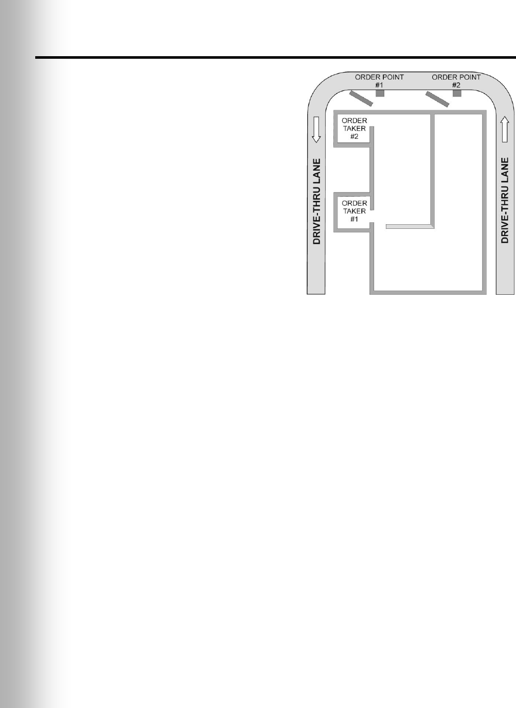
29
6.5 Tandem Operation
(two base stations for two speaker posts in one lane)
In Tandem operation, customers at
Order Point #1 are served by Order
Taker #1, and customers at Order
Point #2 are served by Order Taker #2.
If a customer arrives at Order Point #2
when there is no customer at Order
Point #1, a message will be played
automatically from Speaker Post or
Menu Board #2 saying “Please pull
forward.” The message can be set to
play one time or to repeat every 4
seconds until the customer pulls
forward to Order Point #1 (See section
6.9.2, page 32, Red Message Control,
Switch 6). When a customer arrives at
Order Point #1, Order Taker #1 will be
alerted. If a customer arrives at
Order Point #2 when there is already
a customer at Order Point #1, Order
Taker #2 will be alerted.
Note: If you want to change the pre-recorded
“Please pull forward” message, see section
6.9.1 on page 31.
CAUTION: In tandem operation, if Order Taker #2’s Communicator is set in
the Auto Hands-Free mode, the “Please pull forward” message will not be
played at Order Point #2. If necessary, Order Taker #2 will have to ask the
customer at Order Point #2 to pull forward.
Hands-Free (HF) Mode (Either Order Taker)
With the COMMUNICATOR® power off, press and hold the volume-up ▲ and B
buttons while you press and release the PWR button to turn the power on in the HF
mode. The Communicator will remember this setting.
As a customer approaches Order Point #1, Order Taker #1 will hear an alert tone in
the headset, and will be able to hear the customer at speaker post or menu board #1.
If a customer approaches Order Point #2 when there is already another customer at
Order Point #1, Order Taker #2 will hear an alert tone in the headset, and will be
able to hear the customer at speaker post or menu board #2.
Use the volume-up ▲ and down ▼ buttons to adjust the customer’s voice level in
your headset if necessary.
Order Taker #1, touch and release the A1 button to speak and listen to the customer
at Order Point #1.
Order Taker #2, touch and release the A2 button to speak and listen to the customer
at Order Point #2.
Touch and release the A1/A2 (depending on which Order Taker) or B button to end
communication with the customer.
Touch and release the A1/A2 (depending on which Order Taker) to speak to the
customer again.
If a customer drives away from the speaker post or menu board, the Communicator
will stop transmitting.
Figure 24. Typical Tandem
drive-thru layout

30
Auto Hands-Free (AHF) Mode (Only Order Taker #1)
Order Taker #1 only, with the power off, press and hold the volume-up ▲ and A1
button while you press and release the PWR button to turn the power on in the AHF
mode.
As a customer approaches Order Point #1, you will hear an alert tone in your headset,
and you will be able to hear the customer at speaker post or menu board #1.
Use the volume-up ▲ and down ▼ buttons to adjust the customer’s voice level in
your headset if necessary.
Speak and listen to the customer without pressing any buttons.
Touch and release the A1 or B button to end communication with the customer.
Touch and release the A1 button to speak to the customer again.
If a customer drives away from the speaker post or menu board, the Communicator
will stop transmitting.
Push-To-Talk (PTT) Mode (Either Order Taker)
Note: In Tandem operation, only Order Taker #1 can use the Auto Hands-Free Mode.
If a Communicator is turned off while in the AHF mode, it will automatically be reset
for its previous operating mode.
With the Communicator power off, press and hold the volume-down ▼ and B
buttons while you press and release the PWR button to turn the power on in the
PTT mode. The Communicator will remember this setting.
As a customer approaches Order Point #1, Order Taker #1 will hear an alert tone in
the headset, and will be able to hear the customer at speaker post or menu board #1.
If a customer approaches Order Point #2 when there is already another customer at
Order Point #1, Order Taker #2 will hear an alert tone in the headset, and will be
able to hear the customer at speaker post or menu board #2.
Use the volume-up ▲ and down ▼ buttons to adjust the customer’s voice level in
your headset if necessary.
Touch and hold the A1 button to speak to a customer at Order Point #1, or A2 to
speak to a customer at Order Point #2.
If a customer drives away from the speaker post or menu board, the Communicator
will stop transmitting.
6.6 Internal Communication
To communicate internally with other COMMUNICATOR® operators, press and hold
the B button while talking. Release when finished. In single-lane operations, up to
four Communicator operators can have conference-call type communication by all
pressing the B button. Everyone pressing the B button will hear each other without
interference.
In dual-lane operation, if your system was set up for “Split-B,” internal communication
will be heard only by Communicator operators in your lane. If your system was not
set up for Split-B operation, internal communication will be heard by all
Communicator operators in both lanes. In dual-lane operation, up to three
Communicator operators can have conference-call type communication by all pressing
the B button. Everyone pressing the B button will hear each other without
interference. If a car arrives in a lane while internal communication is taking place,
priority will be given to the respective A channel for customer communication, which
will reduce the number of internal communication channels available.
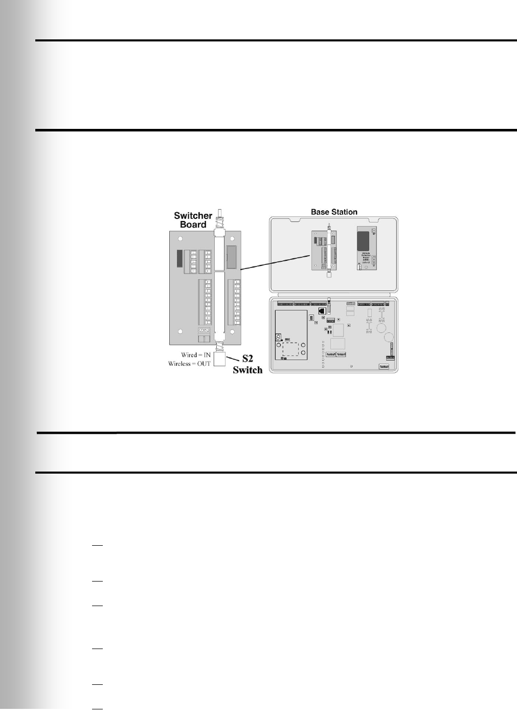
31
6.7 Speed-Team Operation
Speed team operation is used during high-volume times. An order taker wearing a
Communicator relays orders from outside into the store, using button A1, A2 or B.
Note: Speed teams are not used in tandem drive-thrus.
6.8 Wired Backup System
In order to use a wired backup system, you must have a Switcher Board (optional) in
your base station. Open the base station, and look for the board shown in Figure 25.
If there is no Switcher Board, a wired backup system cannot be used. If there is a
Switcher Board, place the S2 switch in the IN position to use the wired backup
system. When using the Wireless IQ system, leave the S2 switch in the OUT position.
6.9 Message Repeater Operation
6.9.1 Recording Messages (Refer to Figure 2 on page 2.)
To record RED MESSAGE: RED MESSAGE switch must be in ON position.
Note: In Tandem base stations, the red message “Please pull forward” is pre-recorded.
Recording a new red message will replace the pre-recorded message.
Press and release the RECORD MODE button on the base station once.
The red MESSAGE RECORD light on the base station will come on.
Press and hold button B on the COMMUNICATOR® and talk into the headset
microphone to record a message (up to 15 seconds).
The MESSAGE RECORD light on the base station will begin blinking.
Release button B.
The record function will stop and the MESSAGE RECORD light will go off.
To record GREEN MESSAGE: GREEN MESSAGE switch must be in ON position.
Press and release the RECORD MODE button on the base station twice.
The green MESSAGE RECORD light on the base station will come on.
Press and hold button B on the Communicator and talk into the headset
microphone to record a message (up to 15 seconds).
The MESSAGE RECORD light on the base station will begin blinking.
Release button B.
The record function will stop and the MESSAGE RECORD light will go off.
Figure 25. S2 switch on Switcher Board

32
6.9.2 Message Repeater Switch Settings
Locate the ”RED MESSAGE” and “GREEN MESSAGE” switches, and the “RED
MESSAGE CONTROL” and “GREEN MESSAGE CONTROL” DIP switches inside the
front door of the base station for the following settings.
Note: If the RED MESSAGE and GREEN MESSAGE switches are both in the ON position,
and are selected for the same output, Red and Green Messages will be played alternately.
After a new message has been recorded or after the base station has lost and regained
power, any message to the outside speaker will always be heard in the Communicator
headset the first three times it plays, whether Switch 1 (DIP switch S13, 8) is in the ON
or OFF position. See Figure 28, page 37.
Red Message Switch:
In the ON position, the RED MESSAGE switch enables the “Red Message” to be
played. A playing message can be cancelled by pressing Communicator button A.
Note: The RED MESSAGE switch does not need to be in the ON position to enable the
“Red Message” to be played when the Tandem switch is on.
Red Message Control:
Switch 1 enables inbound audio from speaker post to be heard while message is playing.
Switch 2 enables message to be played to all Communicators.
Switch 3 enables message to be played on the outside speaker.
Switch 4 enables message to be played on the ceiling speaker.
Switch 5 causes message to be triggered by an external alert signal.
Switch 6 (only used in tandem systems, on secondary base station)
in OFF position, “Please pull forward” message plays once.
in ON position, “Please pull forward” message repeats every 4 seconds.
Switches 7 and 8 not used.
Green Message Switch:
In the ON position, the GREEN MESSAGE switch enables the “Green Message” to be
played. A playing message can be cancelled by pressing Communicator button A.
Green Message Control:
Switch 1 enables inbound audio from speaker post to be heard while message is playing.
Switch 2 enables message to be played to all Communicators.
Switch 3 enables message to be played on the outside speaker.
Switch 4 enables message to be played on the ceiling speaker.
Switch 5 causes message to be triggered by an external alert signal.
Switch 6 causes a 3 second delay before message is played.
Switch 7 not used
Switch 8 selects a “dual-beep” vehicle tone for the Lane 2 base station in a dual lane
configuration.

33
7. IN CASE OF PROBLEMS
PROBLEM
PROBABLE CAUSE
SOLUTION
“Battery failed” is heard
in headset when
COMMUNICATOR®
PWR button is pressed.
Battery may be defective.
Replace battery. Call HME.*
“Headset failed” is heard
in headset when
Communicator PWR
button is pressed.
Headset may be defective.
Use another headset. Call HME.*
You hear your echo in
headset earpiece when you
speak into Communicator
microphone.
Outside speaker and microphone may
not be properly installed.
Be sure speaker and microphone are isolated from each
other, and are tightly mounted with enough foam packed
around each of them to absorb vibrations.
Outbound and/or inbound audio level
may be set too high.
Set outbound audio level just high enough to be heard by
customers. Lower inbound audio to comfortable level.
VAA controls may need to be
adjusted. See section 5.2, page 25.
Adjust VAA Level control on the front panel of the base
station clockwise to reduce inbound audio level when you
are speaking into the headset microphone.
Adjust VAA attenuation level, R348 on the base station
circuit board (Figure 26 #13, page 35) clockwise to reduce
inbound audio level when you are speaking into the headset
microphone.
NOTE: If the inbound level is too low, you will not hear
the customer.
No sound is heard in
Communicator headset
when you press button A
and speak into
microphone.
Power may be off at base station.
Check circuit breaker for building.
Power supply in base station may not
be working.
Check power supply indicator lights on base station.
If no light is lit, be certain AC power adapter is plugged into
AC electrical outlet, and is connected to J29 on base station
audio circuit board.
Communicator power may not be on.
Press PWR button on Communicator. Be certain power light
goes on and switches from red to green.
Volume may not be set correctly.
Adjust volume with Volume-up and down buttons.
Battery may be low or defective.
Check Communicator Power light. If not lit, replace battery.
Headset may be defective.
Use another headset. Call HME.*
Communicator may not be registered.
Register Communicator.
Channel A or B is not
working.
Communicator power may not be on.
Press PWR button on Communicator. Be certain power light
goes on and switches from red to green.
Battery may be low or defective.
Check Power light. If not lit, replace battery.
“A” Talk or “B” Talk light on base
station does not light when button A
or B on Communicator is pressed.
Use another Communicator.
Call HME.*
Communicator may not be registered.
Register Communicator.
Outbound sound is too
low.
Outbound volume may be set too low
for environment.
Turn outside speaker volume control, on front panel of base
station, clockwise until volume is satisfactory.
No outbound sound;
Customer cannot hear
anything.
System may be set for speed-team
operation.
Be certain SPEED TEAM button on base station is in
OFF position.
There may be loose wires on outside
speaker or base station circuit board.
Check VEHICLE PRESENT light on base station.
Check outside speaker wire connections in base station and
at outside speaker.
Defective speaker or base station.
Call HME.*

34
PROBLEM
PROBABLE CAUSE
SOLUTION
Customer cannot be heard
in push-to-talk PTT)
operation.
System may be set for speed-team
operation.
Be certain SPEED TEAM button on base station is in OFF
position.
Base station may be set for wrong
drive-thru mode (full or half-duplex).
Check S6 DIP switch #1 at bottom of base station audio
circuit board. It should be ON for full-duplex, OFF for half-
duplex operation.
Only intermittent voice
can be heard in headsets.
Transmitter antenna connectors on
base station transceiver circuit board
may be loose or damaged.
Be certain antennas are screwed securely
onto base station. Check transmitter antenna cable
connection at ANT1 and ANT2 near lower-left corner of
transceiver circuit board. Pull and remove each connector
plug, and check to be certain pin inside it is not bent. If
not, call HME.*
Circuit board may be defective.
Call HME.*
VAA level is too sensitive.
Reduce VAA level (See Figure 2, page 2) so inbound
audio is reduced only when order taker speaks into
microphone.
Personnel hear customers
in ceiling speaker or
headsets, but cannot hear
each other.
Circuit board may be defective.
Check to see if status lights on
base station are lit. Call HME.*
Defective COMMUNICATOR®.
Use another Communicator. Call HME.*
No tone or sound is heard
in ceiling speaker or
headsets when vehicle
enters drive-thru lane.
Power interruption may have caused
vehicle detection circuit to be out of
balance.
When no vehicle is in the drive-thru lane, move the
vehicle detector override switch on the base station to the
RESET position, then back to the NORMAL position.
System may be set for speed-team
operation.
Be certain SPEED TEAM switch on base station is in
OFF position.
Connector may be loose, or S6 DIP
switch #8 is not set to ON.
Check all connectors in base station, and be certain S6 #8
is set to ON. Call HME.*
Personnel cannot hear
customers in ceiling
speaker or headsets.
There may be loose wires on base
station circuit board.
Check all connections on base station circuit boards.
System may be set for speed-team
operation.
Be certain SPEED TEAM switch on base station is in
OFF position.
Outside speaker, audio circuit board
or vehicle detector board failed.
Call HME.*
VAA attenuation set too high
Reduce attenuation. (See Figure 26 #13, page 35)
Headset has intermittent
sound.
Battery may be low.
Replace battery.
Headset may be defective.
Use another headset. Call HME.*
There is still sound in
headset after all customers
have been served.
VEHICLE DETECT switch on base
station may be in the OVERRIDE
position.
Be certain switch is in the NORMAL position.
Vehicle detector may be locked up.
Slide VEHICLE DETECT switch back and forth slowly
twice.
Battery charger is not
working.
Charger may not be plugged in.
Be certain charger is plugged in.
If it still is not working, call HME.*
Red or Green message will
not play.
Switch not on.
Be certain respective Red or Green message repeater
switch on base station is in the ON position, and routing
switches are set.
COMMUNICATOR®
“Registration failed”
message heard in headset.
Lights stay red.
Base station power not on.
Check power supply indicator lights on base station.
If no light is lit, be certain AC power adapter is plugged into
AC electrical outlet, and is connected to J29 on base station
audio circuit board.
Registration button not pushed.
Repeat registration procedure, pages 5 and 6.
Call HME.*
* For assistance, call HME at 1-800-848-4468, or Fax 858-552-0172.
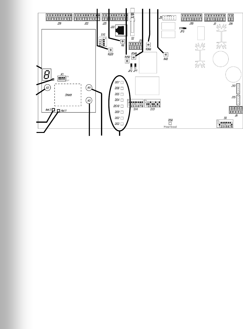
35
1. COMMUNICATOR® ID display
2. Status light
3. Reset button
4. Ant2 antenna connector
5. Ant1 antenna connector
6. Start registration button
7. Clear all registration button
8. Indicator lights DS7 Record
(See Figure 2) DS6 Vehicle Present
DS5 “B” Talk
DS4 “A” Talk
DS10 +5V Xcvr
DS9 +5V
DS2 +12V
DS3 +22V
9. Line-in level adjustment
10. Transmit audio level adjustment
11. Transmit message level adjustment
12. Record mode button
13. VAA attenuation level adjustment
14. Line-out level adjustment
15. Inbound audio level adjustment
6 7 8
9 10 11 12 13 14 15
1
2
3
4
5
Figure 26. Base Station internal controls and indicators
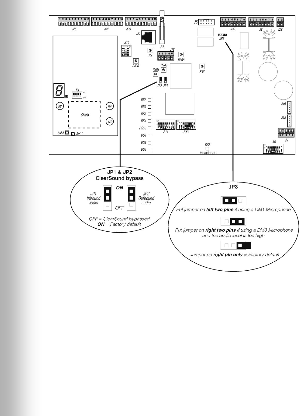
36
Figure 27. Base station jumper settings
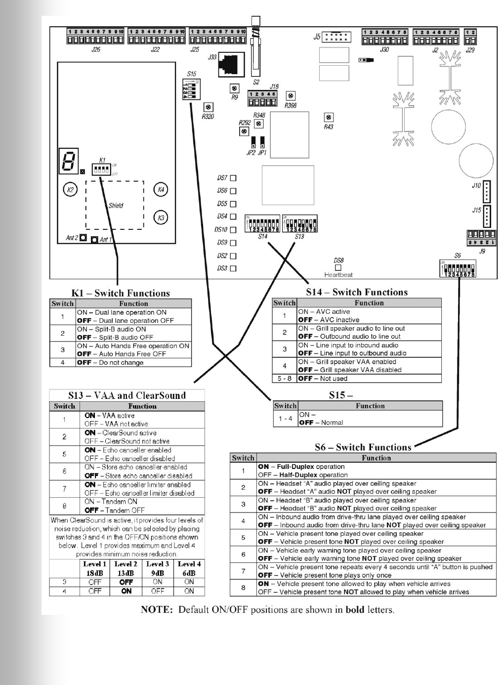
37
Figure 28. Base station DIP switch functions
Figure 29. Base station DIP switch functions

38
8. EQUIPMENT SPECIFICATIONS
Base Station
Voltage input 16VAC ±2.5V
AC current input 2.5A maximum
Audio distortion 5% maximum level
Outside speaker output 3 watts RMS into 8 ohms
Ceiling speaker power 3 watts RMS into 8 ohms
TX/RX frequency 2400MHz – 2483.5MHz
Dimensions 7.75”H x 12.75”W x 3.8”D
(197 mm x 323 mm x 97 mm)
Weight 4 lbs (1.81 kg) maximum
COM6000BP Belt-Pac COMMUNICATOR®
Battery type 3.6V Lithium ion
Battery life 18 - 20 hours (typical)
RF frequency 2400MHz – 2483.5MHz
Weight 5.1 oz (.133 kg) with battery
Odyssey IQ Headset COMMUNICATOR®
Battery type 3.6V Lithium ion
Battery life 18 - 20 hours (typical)
RF frequency 2400MHz – 2483.5MHz
Weight 5.7 oz (.16 kg) with battery
AC40 Battery Charger
Voltage input 16.5VAC
Charging time 2 hrs maximum
Dimensions 7.6” x 4.6” x 2.6”
(193mm x 117mm x 66mm)
Weight 1.5 lb (.68 kg)
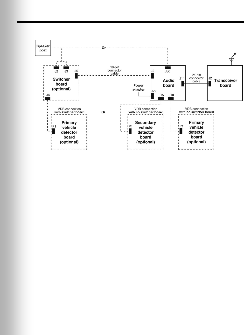
39
9. BLOCK DIAGRAM
Figure 29. Typical Wireless IQ Base Station block diagram

40
10. BASE INTERFACE DESCRIPTION
10.1 Audio Circuit Board
J1 – ATE Connector (not installed)
J1,1 Microphone 1
J1,2 Microphone 2
J1,3 /Vehicle 2 tone force
J1,4 /Vehicle present
J1,5 Vehicle detector power
J1,6 /Vehicle 1 tone
J1,7 Receive Audio B1
J1,8 B Talk
J1,9 Power ground
J1,10 +5 VDC
J1,11 +5 Xcvr
J1,12 +12 VDC
J1,13 A Talk
J1,14 Not used
J1,15 +22 VDC
J1,16 Ceiling speaker output
J1,17 RX audio A1
J1,18 TX/RX audio ground
J1,19 TX audio 1
J1,20 Message audio
J2 – Speaker In/Out
J2,1 Ground
J2,2 /A Talk
J2,3 Relay 1 Common
J2,4 Relay 1 Normally Open
J2,5 Relay 1 Normally Closed
J2,6 Ceiling speaker +
J2,7 Ceiling speaker
J2,8 Ground
J5 – Switcher Board Interface
J5,1 Microphone 1
J5,2 Microphone 2
J5,3 Ground
J5,4 +12VDC
J5,5 Not used
J5,6 Negative vehicle detect input
J5,7 Vehicle detector power
J5,8 Not used
J5,9 Outside speaker –
J5,10 Outside speaker +
J9 – Input/Output Connector
J9,1 Early warning
J9,2 Ground
J9,3 Service window
J9,4 Ground
J9,5 Alert input
J10 – Vehicle Detector Board
Interface 1 (Primary)
J10,1 Negative vehicle detect signal
J10,2 Vehicle detector power
J10,3 Ground
J10,4 Not used
J10,5 Not used
J11 – Transceiver Interface
J11,1 XSCL
J11,2 XSDA
J11,3 +5V Xcvr
J11,4 Power Ground
J11,5 Reset
J11,6 Power Ground
J11,7 SCL
J11,8 /A1 Talk
J11,9 TX Audio 1
J11,10 /B1 Talk
J11,11 Ground
J11,12 Car 1
J11,13 RX Audio A1
J11,14 Ground
J11,15 Ground
J11,16 SDA
J11,17 RX Audio B1 or B1 + B2
J11,18 TX Audio 2
J11,19 /A2 Talk
J11,20 Ground
J11,21 /B2 Talk
J11,22 RX Audio A2
J11,23 Car 2
J11,24 Ground
J11,25 Ground
J11,26 Rx Audio B2 or B1 + B2
J15 – Vehicle Detector Board
Interface 2 (Secondary)
J15,1 Negative vehicle detect signal
J15,2 Vehicle detector power
J15,3 Ground
J15,4 Not used
J15,5 Not used

41
J18 – Line In/Out
J18,1 Line out
J18,2 Ground
J18,3 Line in
J18,4 Ground
J18,5 Not used
J22 – Base Station Interface Connector
in Primary Base Station
J22,1 Vehicle detect input
J22,2 Vehicle detect output
J22,3 /A2 Talk
J22,4 /B2 Talk
J22,5 Car 2
J22,6 Ground
J22,7 TX Audio 2
J22,8 Ground
J22,9 RX Audio A2
J22,10 RX Audio B2 or B1 + B2
J25 – Remote Switch and
Vehicle Detect 2 Interface
J25,1 Speed Team Remote Common
J25,2 +5VDC
J25,3 Ground
J25,4 Not used
J25,5 Record Remote
J25,6 Ground
J25,7 Not used
J25,8 Relay 2 Normally open
J25,9 Relay 2 Common
J25,10 Relay 2 Normally Closed
J26 – Base Station Interface Connector
in Secondary Base Station
J26,1 Vehicle detect output
J26,2 Vehicle detect input
J26,3 /A2 Talk
J26,4 /B2 Talk
J26,5 Car 2
J26,6 Ground
J26,7 TX Audio 2
J26,8 Ground
J26,9 RX Audio A2
J26,10 RX Audio B2 or B1 + B2
J29 – AC Power
J29,1 16VAC power input
J29,2 16VAC power input
J30 – Menu Board Interface
(Without Switcher Board)
J30,1 Microphone 1
J30,2 Microphone 2
J30,3 Ground
J30,4 +12VDC
J30,5 Negative vehicle detect input
J30,6 Aux Negative vehicle detect input
J30,7 Outside speaker –
J30,8 Outside speaker +
J33 –
J33,1 TX Audio 2
J33,2 +12VDC
J33,3 /A2 Talk
J33,4 /B2 Talk
J33,5 Alert
J33,6 Aux Negative Detect
J33,7 Ground
J33,8 RX Audio B2
JP1 – ClearSound Bypass Jumper
JP1,1 Audio channel 1 input
JP1,2 Inbound Audio
JP1,3 Audio channel 1 output
JP2 – ClearSound Bypass Jumper
JP2,1 Audio channel 2 input
JP2,2 Outbound Audio
JP2,3 Audio channel 2 output
10.2 Transceiver Circuit Board
J2 –
J2,1 +5VDC
J2,2 Ground
J2,3 NC
J2,4 Ground
J2,5 NC
J2,6 /A1 Talk
J2,7 Tx audio 1
J2,8 /B1 Talk
J2,9 Ground
J2,10 Car 1

42
J2,11 Rx audio A1
J2,12 Ground
J2,13 Ground
J2,14 NC
J2,15 Rx audio B1 or B1 + B2
J2,16 Tx audio 2
J2,17 /A2 Talk
J2,18 Ground
J2,19 /B2 Talk
J2,20 Rx audio A2
J2,21 Car 2
J2,22 Ground
J2,23 Ground
J2,24 Rx audio B2, or B1 + B2
10.3 Switcher Circuit Board
J1 – DM1 Interconnect
J1,1 Microphone in
J1,2 Microphone in
J1,3 Ground
J1,4 +12VDC
J1,5 Not used
J2 – Menu Board Interconnect
J2,1 Speaker/microphone in/out
J2,2 Speaker/microphone in/out
J2,3 Shield
J2,4 Speaker out
J2,5 Speaker out
J3 – Detector/Timer Interconnect
J3,1 Loop
J3,2 Loop
J3,3 Positive vehicle detection signal
J3,4 Ground
J3,5 Negative vehicle detection signal
J3,6 Greet
J3,7 Greet
J3,8 Negative vehicle detection signal
J3,9 Ground
J3,10 Positive vehicle detection signal
J4 – Backup System Interconnect
J4,1 Loop
J4,2 Loop
J4,3 Negative vehicle detection signal
J4,4 Ground
J4,5 Positive vehicle detection signal
J4,6 Not used
J4,7 Speaker/microphone in/out
J4,8 Speaker/microphone in/out
J4,9 +12V to +48V in
J4,10 +12V to +48V in
J5 – Audio Board Interconnect
J5,1 Microphone 1
J5,2 Microphone 2
J5,3 Ground
J5,4 +12VDC
J5,5 Positive vehicle detector input
J5,6 Negative vehicle detector input
J5,7 Vehicle detector power
J5,8 Not used
J5,9 Outside speaker –
J5,10 Outside speaker +
J6 – Vehicle Detector Board
Interconnect
J6,1 Vehicle detector signal
J6,2 Vehicle detector signal
J6,3 Ground
J6,4 Not used
J6,5 Not used
10.4 Vehicle Detector Circuit Board (Optional)
P1 – Audio Board Interface Cable Connector
P1,1 Signal
P1,2 Power
P1,3 Ground
TB1 – Vehicle Detector Loop Connector

43
11. WIRING DIAGRAMS
Page 44, Figure 30 — Full-Duplex Wireless IQ with VDB but no Switcher Board
Page 45, Figure 31 — Full-Duplex Wireless IQ with VDB, Switcher Board, DM1 or
DM3 Microphone and IC300
Page 46, Figure 32 — Full-Duplex Wireless IQ with VDB, Switcher Board
and DM1 or DM3 Microphone
Page 47, Figure 33 — Half-Duplex Wireless IQ with VDB but no Switcher Board
Page 48, Figure 34 — Half-Duplex Wireless IQ with VDB and Switcher Board
Page 49, Figure 35 — Wireless IQ Dual-Lane, Primary to Secondary Base Station
connections
Page 50, Figure 36 — Wireless IQ Tandem, Primary to Secondary Base Station
connections
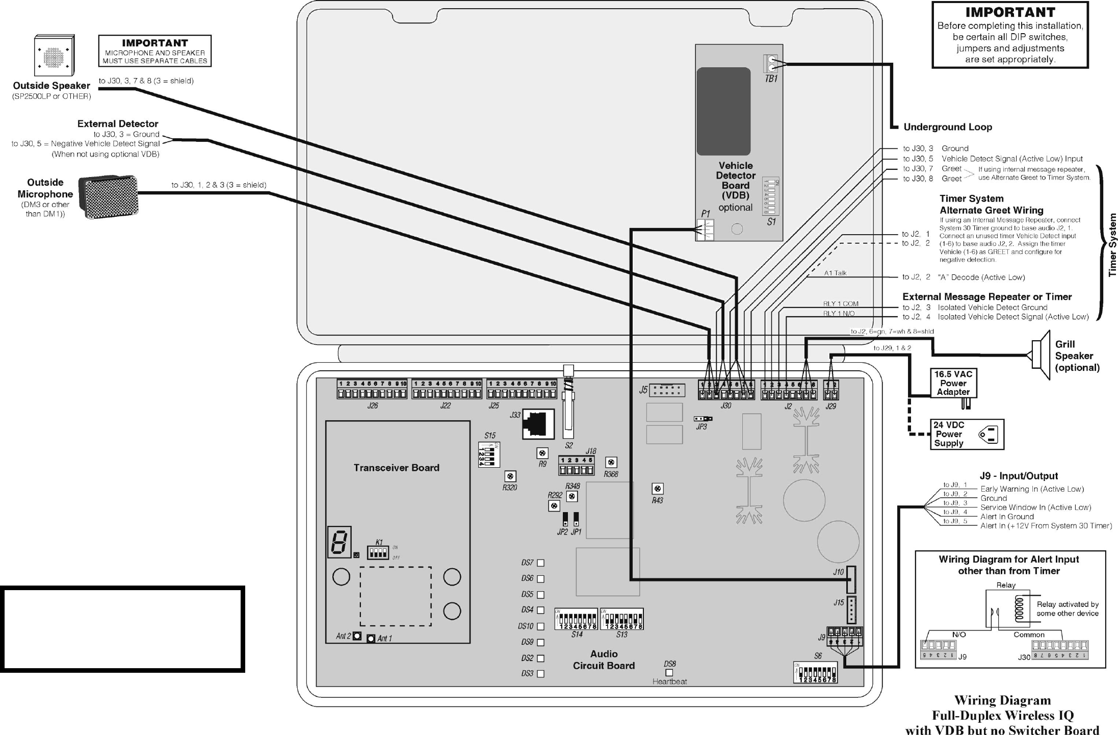
44
Figure 30.
For dual-lane primary to secondary
base station connections, see Figure 35.
For tandem primary to secondary
base station connections, see Figure 36.
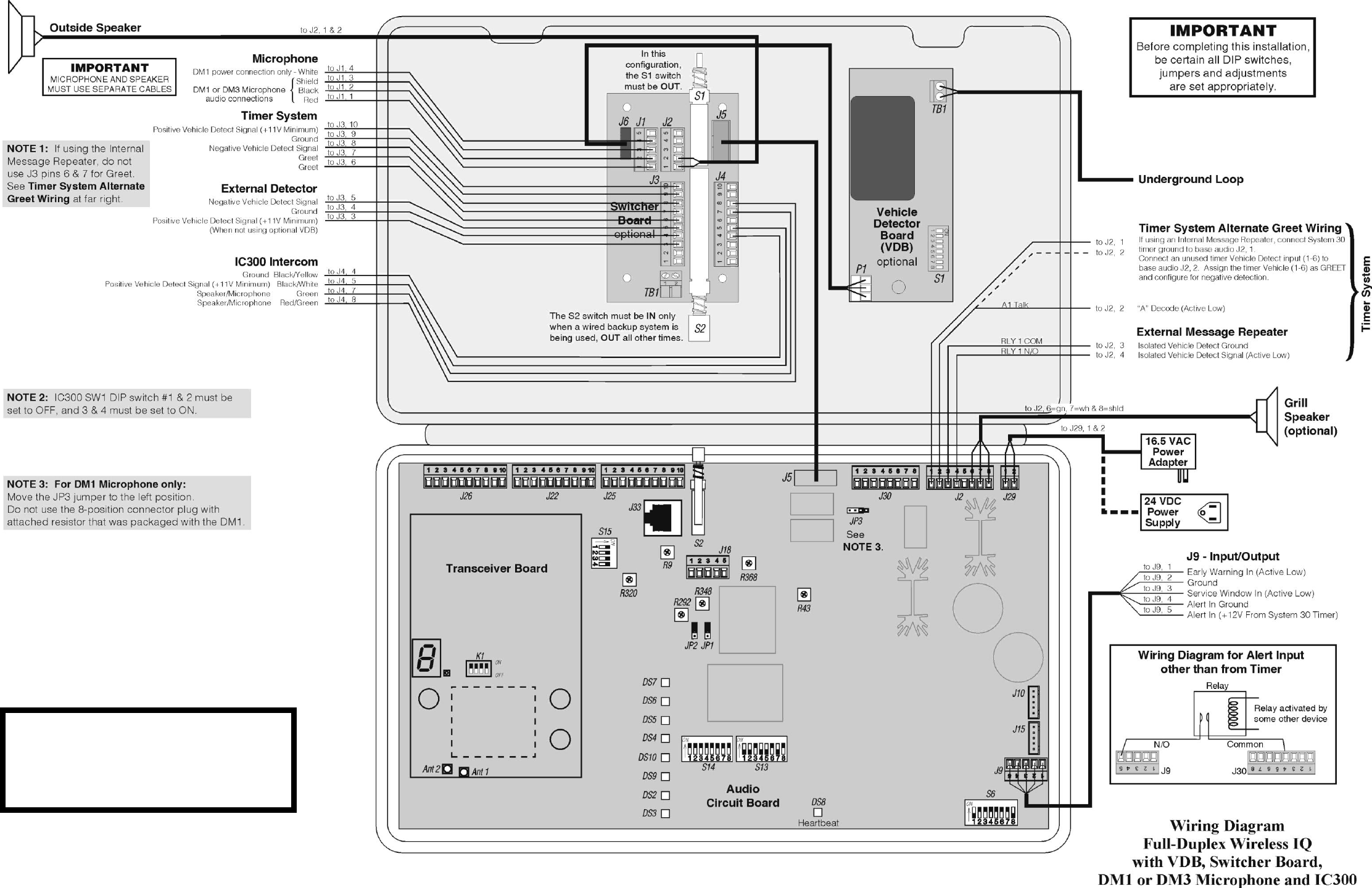
45
Figure 31.
For dual-lane primary to secondary
base station connections, see Figure 35.
For tandem primary to secondary
base station connections, see Figure 36.
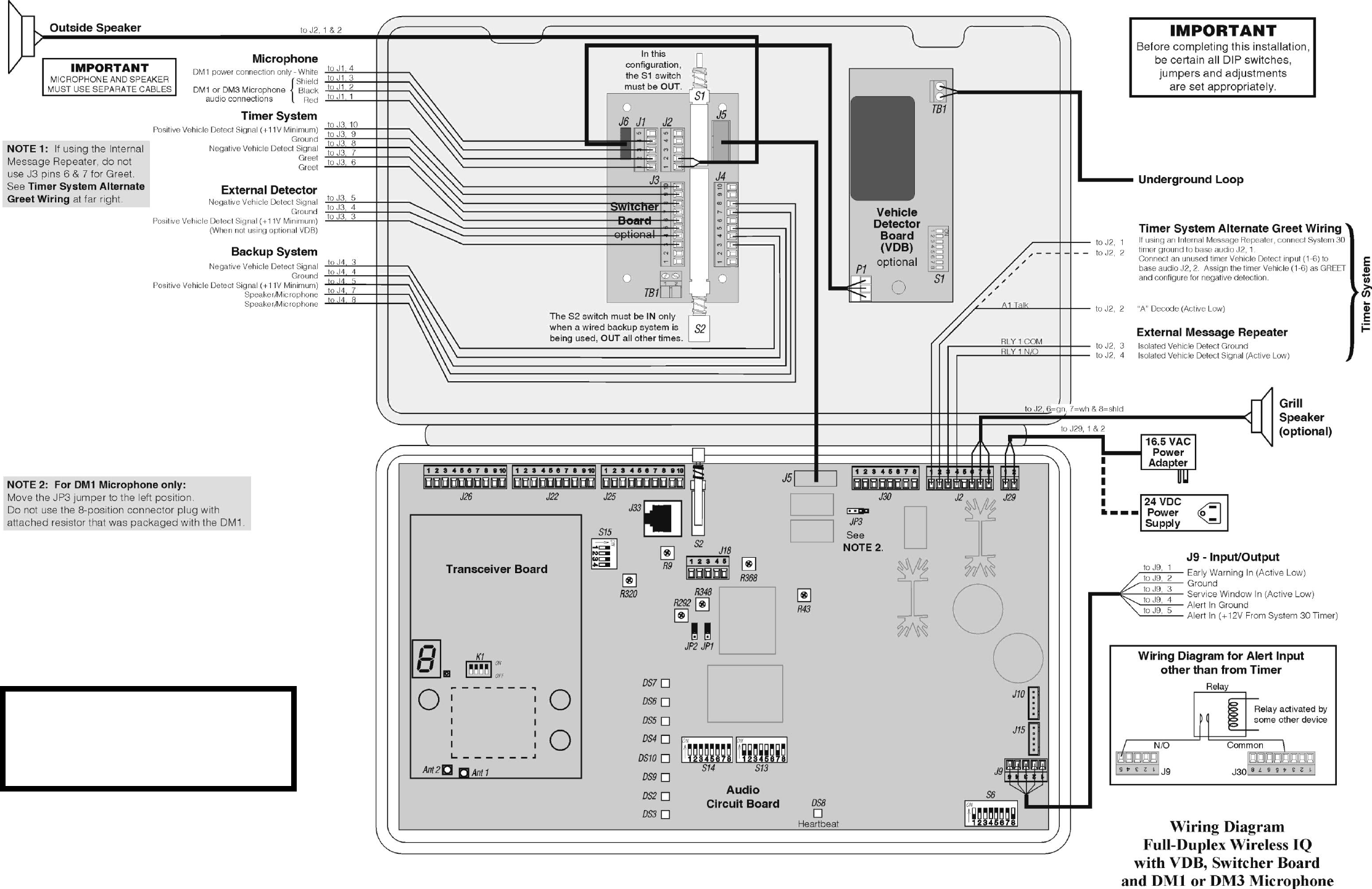
46
Figure 32.
For dual-lane primary to secondary
base station connections, see Figure 35.
For tandem primary to secondary
base station connections, see Figure 36.
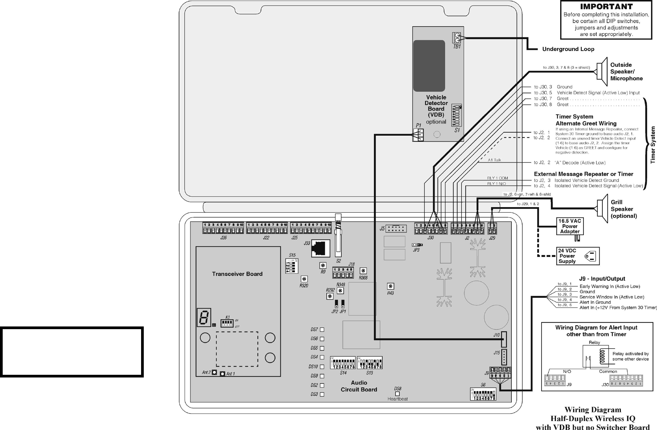
47
Figure 33.
For dual-lane primary to secondary
base station connections, see Figure 35.
For tandem primary to secondary
base station connections, see Figure 36.
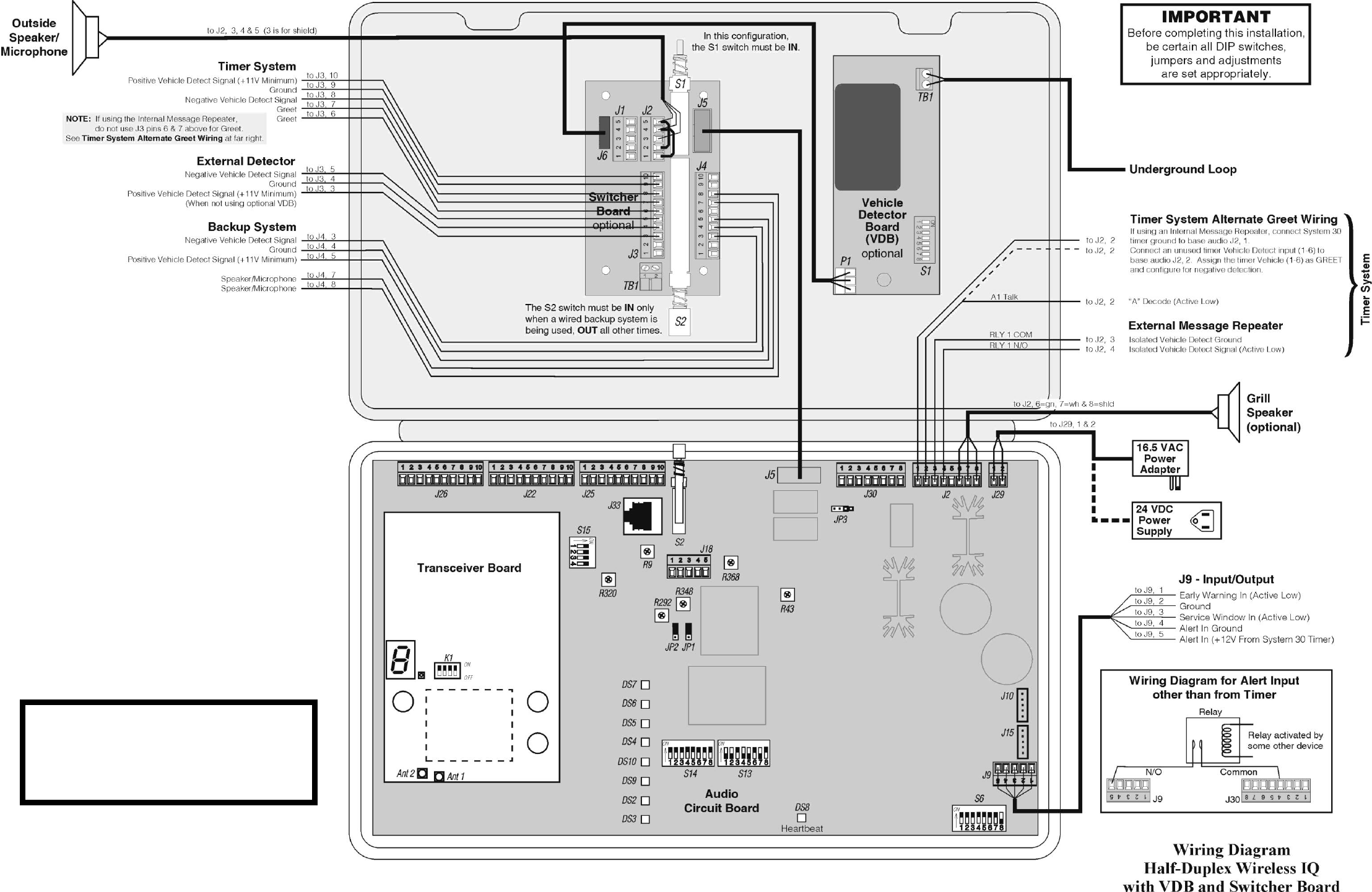
48
Figure 34.
For dual-lane primary to secondary
base station connections, see Figure 35.
For tandem primary to secondary
base station connections, see Figure 36.
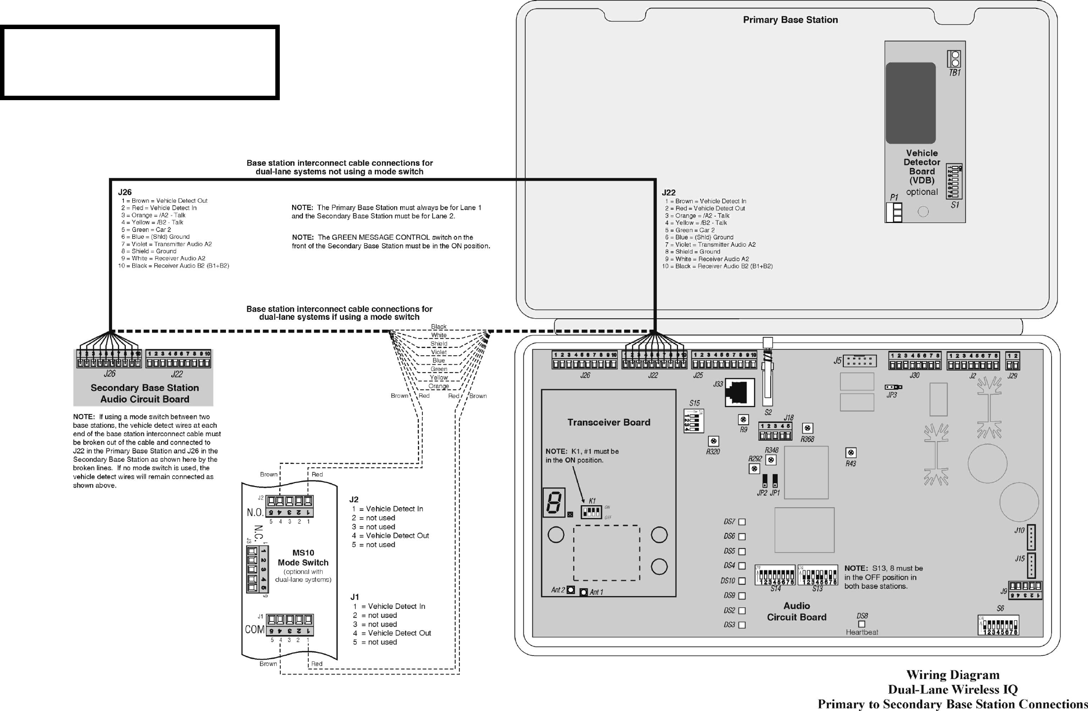
49
Figure 35.
This diagram only shows how to interconnect the
primary and secondary base stations in dual-lane
configurations. For all other equipment connections,
refer to Figures 30 – 34.
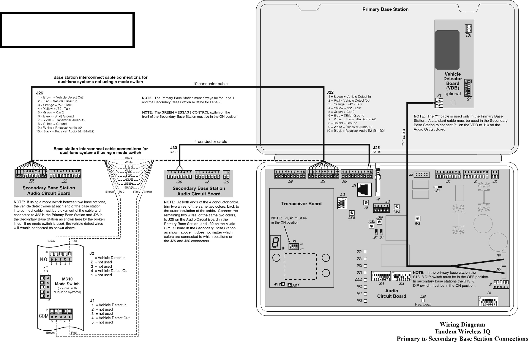
50
Figure 36.
This diagram only shows how to interconnect the
primary and secondary base stations in tandem
configurations. For all other equipment connections,
refer to Figures 30 – 34.