HM Electronics HS500 SYS500 Headset User Manual 400468
HM Electronics Inc SYS500 Headset 400468
Contents
- 1. manual
- 2. final manual
final manual

HME# 400468
Rev -
3/26/03
System 500
Wireless Drive-Thru Audio System
Operating Instructions

Table of Contents
I. GENERAL...............................................................................................................1
II. EQUIPMENT FUNCTIONS AND USE...................................................................1
A. Base Station .....................................................................................................................................................2
B. Headset .....................................................................................................................................................4
C. Battery Charger...............................................................................................................................................7
III. SYSTEM 500 OPERATION.....................................................................................8
A. Single -Lane Operation...................................................................................................................................8
B. Dual-Lane Operation......................................................................................................................................9
C. Speed-Team Operation ..................................................................................................................................9
D. Message Repeater Operation ......................................................................................................................10
IV. EQUIPMENT CARE AND CLEANING................................................................11
A. Proper Handling ............................................................................................................................................11
B. Cleaning ...................................................................................................................................................11
V. IN CASE OF PROBLEMS.....................................................................................12
VI. SPECIFICATIONS................................................................................................16
VII. OPTIONAL EQUIPMENT ....................................................................................17
VIII. FCC NOTICE........................................................................................................17
List of Figures
Figure Title Page
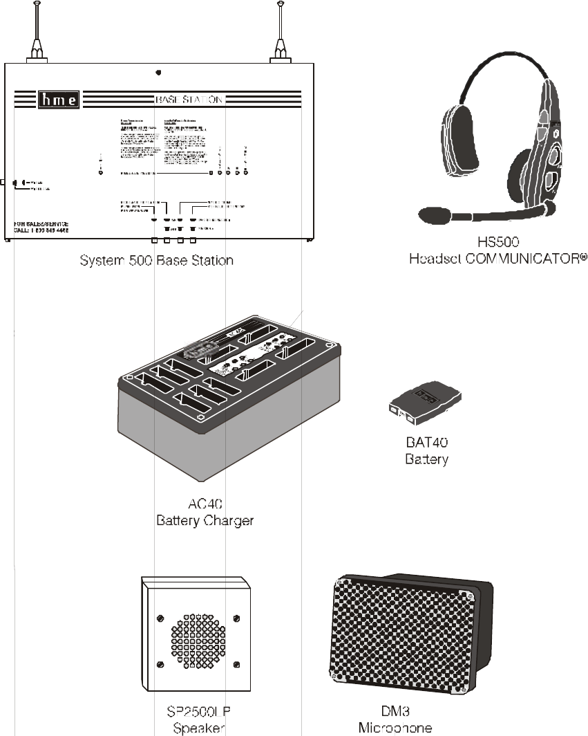
1 System 500 equipment..........................................................................................................................1
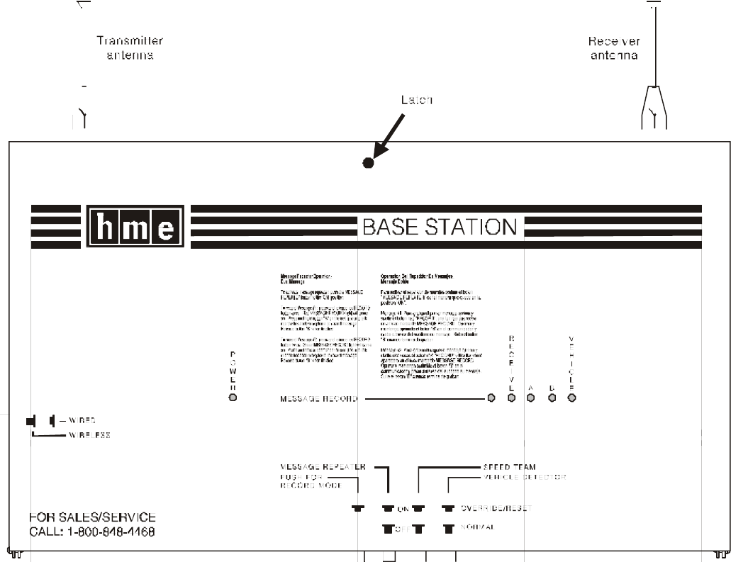
2 Base station exterior..............................................................................................................................2
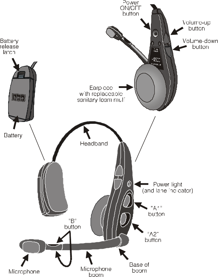
3 Headset features and controls ..............................................................................................................4
4 Correct wearing of headset..................................................................................................................5
5 Battery removal......................................................................................................................................6
6 Battery replacement ..............................................................................................................................6
7 Battery charger.......................................................................................................................................7
8 Base station circuit boards................................................................................................................ 14
The HME logo and the word COMMUNICATOR
®
are registered trademarks of HM
Electronics, Inc.
© Copyright HM Electronics, Inc.
-
March 2003
1
I. GENERAL
The System 500 is a wireless audio system primarily for use at
quick-service restaurants.
II. EQUIPMENT FUNCTIONS AND USE
Figure 1. System 500 equipment
2
A. Base Station
The base station is the electronic heart of the System 500. It
contains the circuitry through which all functions of the drive-
thru audio system are channeled.
External base station features are shown in Figure 2, and
described on page 3. Its internal features are shown in Figure
8, and the base station circuit board switches and adjustments
are listed on page 15.
Figure 2. Base station exterior
3
Base Station External Features
Front –
• POWER light is on when the base station has power.
• MESSAGE RECORD light is on RED when the base station is
ready to record
message #1 for the message repeater, and blinking RED while
message #1 is being recorded. It is on GREEN when the base
station is ready to record message #2 for the message
repeater, and blinking GREEN while message #2 is being
recorded. The MESSAGE REPEATER button must be pushed IN.
• RECEIVE light is on during channel-A and channel-B
transmissions, and is used for troubleshooting.
• “A” light is on during channel-A transmission.
• “B” light is on during channel-B transmission.
• VEHICLE light is on when a vehicle is present in the drive-
thru lane or when the system is in vehicle-detect override.
Bottom –
• PUSH FOR RECORD MODE button must be pushed IN and released
once to prepare the base station to record message #1 for
the message repeater, or pushed IN and released twice to
record message #2.
• MESSAGE REPEATER button must be pushed IN to use the
message repeater, OUT when the message repeater is not
being used.
• SPEED TEAM button must be pushed IN for speed-team
operation, OUT for normal drive-thru operation
• VEHICLE DETECTOR button must be pushed and left IN to
override a vehicle detector; to reset vehicle detector,
push IN and leave IN for 5 seconds, then push again and
leave OUT for normal vehicle detection.
Left Side –
• WIRED/WIRELESS button must be OUT when using the wireless
System 500, IN when using a wired backup system.
4
B. Headset
1. Features and Controls
Figure 3. Headset features and controls

5
2. How to Wear the Headset
• Wear the microphone on your right or
left side.
• Wear the battery end of the headset
above your
ear, on the side of your head opposite
the earpiece.
• Adjust the headband for a comfortable
fit.
• Hold the microphone boom at its base (See
Figure 3) and pivot the boom up or down
to adjust the microphone position to the
side of your mouth as shown in Figure 4.
3. How to Use the Headset
The headset control buttons are touch-
sensitive.
They will activate when only slightly
touched. Use your fingertips, not your fingernails, to touch
the buttons.
a. Power On/Off
Power Light
• The headset power light is red for lane 1, green for
lane 2.
• The headset power light blinks while the headset is
transmitting your voice.
• The headset power light is ON steady when the headset is
not transmitting.
Power On
• Press and release the power ON/OFF button to turn the
headset on.
• A voice message in the headset says “Power on, lane one
(or two).”
• The headset power light blinks green, then goes on
steady red (lane 1)
or green (lane 2).
Power Off
• Press and hold the power ON/OFF button 2 seconds.
• A voice message in the headset earpiece says “Power
off.”
• The headset power light goes off.
b. Volume Up/Down
Single-Step Volume Adjustment
• Lightly touch and release the Volume-up or Volume-down
button.
• A beep sounds in the headset earpiece each time the
button is pressed.
• As the volume increases, one step at a time, the pitch of
the beep increases.
Figure 4.
Correct wearing
of headset
6
As the volume decreases, one step at a time, the pitch of
the beep decreases.
• When the same high or low pitch repeats each time you
touch a Volume-up
or down button, you have reached the maximum or minimum
volume level.
Continuous Volume Adjustment
• Lightly touch and hold the Volume-up or Volume-down
button.
• The volume increases or decreases continuously while the
button is held.
• A series of beeps, of increasing or decreasing pitch, sound
in the headset earpiece until the volume reaches maximum or
minimum.

7
4. Headset Operating-Mode Settings
Most stores have installed systems with Hands-Free capability,
but some have not. If you are uncertain whether or not your
System 500 has Hands-Free capability, do the following test.
a. Auto-Hands-Free Setting
The auto-hands-free (AHF) feature allows one operator to
communicate with a customer in one drive-thru lane without
pressing any buttons. Other operators can listen. If the
first operator turns the AHF feature off, another operator
can turn it on.
CAUTION: Only one HS500 per lane can be set in the auto-
hands-free mode, or interference will occur when a customer
enters the drive-thru lane.
• With the power already on, press and hold the Power button and
touch the Volume-down button — You will hear “Auto-hands-free
on” or “Auto-hands-free off”
NOTE: You must touch the Volume-down button within 2 seconds
after pressing the Power button, or you will turn the power off
and have to begin again. If the auto-hands-free feature does
not come on, you may need to reconfigure the S1 switch in the
base station. Call HME Customer Support at 1-800-848-4468
for assistance.
• The last auto-hands-free on/off message you hear will
remain in effect until you change it again or turn the
headset power off.
b. Configuration Settings
• With the power already on, press and hold the Power button
and press the B button. NOTE: You must press the B button
within 2 seconds after pressing the power button, or you
will turn the power off and have to begin again.
• You will hear “Configuration” in the headset.
• Select the desired configuration setting described
below.
• When finished, press and release the B button to exit
the configuration-settings mode. You will hear “Power
on, lane (one or two)” in the headset.
• Configuration settings will remain in effect until you
change them again.
Hands-free On/Off Configuration
• Touch and release the Volume-down button — you will hear
“Hands-free on.”
• Touch and release the Volume-down button again — you will hear
“Hands-free off.”
• You will continue to hear “Hands-free on” or “Hands-free
off ” messages alternating each time you touch and
release the Volume-down button.
When a car is at the speaker post (or menu board), touch and
hold the appropriate “A” button. If you can hear the sound of
the car or the customer with the “A” button held, you have
Hands
-
Free capability.
8
• The last hands-free on/off message heard will be
selected when you exit the configuration-settings mode.
Single/Dual Lane Configuration
• Touch and release the A1 button — you will hear “Single
lane.”
• Touch and release the A1 button again — you will hear
“Dual lane.”
• You will continue to hear “Single lane” or “Dual lane”
messages alternating each time you touch and release the
A1 button.
NOTE: If you do not hear a “Single lane” or “Dual lane”
message, you may need to reconfigure the S1 switch in the
base station. Call HME Customer Support at 1-800-848-4468
for assistance.
• The last single/dual lane message heard will be selected
when you exit the configuration-settings mode.
9
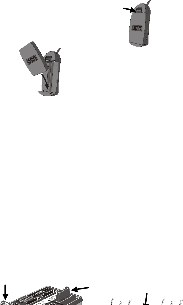
Figure 6.
Battery replacement
5. Battery Removal and Replacement
If you hear “Headset Battery Low” in the headset, its battery
needs to be replaced and recharged. HS500 batteries need be
recharged after 12-13 hours of normal use.
a. Battery Removal
• Push the battery-release latch upward.
• Pull the battery out from the top.
b. Battery Replacement
• Place the end of a battery into
the battery
compartment, with its metal
contacts
downward.
• Press the top of a battery into the
battery
compartment until it snaps in place
under the battery-release latch.
C. Battery Charger
Up to four headset batteries can be charged in the charger at the
same time. Charging time is approximately 2 hours. The battery
status lights next to each charging port are explained below. Up to
six fully charged batteries can be kept in the battery storage ports.
• Insert a battery in one of four charging ports until it clicks in
place.
• The yellow light next to a charging port stays on while it is
empty. When a battery is in a charging port, a yellow light
flashing next to it indicates CHARGE PENDING, which means the
temperature where the charger is located is out of the battery’s
operating range (32o-104oF, 0o-40oC). Adjust the room temperature
or move the charger to a cooler area.
When battery is in a port, a yellow light on steady next to it
indicates CHARGE FAILED. Follow the diagnostic instructions on
the side of the battery charger.
• The red CHARGING light next to a charging port stays on while a
battery in it is charging.
• The green READY light next to a charging port goes on when a battery
in it is fully charged.
• Remove the fully charged battery from its charging port and place
it in a storage port.
CAUTION: Do not remove batteries from the charger until the
green READY light is lit, or the charger will reset and the
charge cycle will begin again.
Figure 5.
Battery removal
Batt
e
ry
relea
se
Battery in
storage
port
Battery in
charging
port
Label on
battery
charger

10
III. SYSTEM 500 OPERATION
The headset can be operated in Hands-Free, Auto-Hands-Free or Hands-
Free-Off modes.
If your store does not have Hands-Free capability, you should
operate the System 500 according to section A.3. below in single-
lane stores, or B.3. (page 9) in dual-lane stores.
If you are uncertain if your store has hands-free capability, refer
to section 4 on page 6.
In the Hands-Free and Auto-Hands-Free modes, you can transmit and
receive communication at the same time, as in a normal telephone
conversation. In the Auto-Hands-Free mode, transmission and
reception are activated automatically when a customer drives into the
drive-thru lane. In the Hands-Free mode, transmission and reception
are activated by touching and releasing one of the A buttons on the
headset. In the Hands-Free-Off mode, you must touch and hold one of
the A buttons on the headset while speaking to the customer.
When a customer arrives in the drive-thru lane, you will hear a
single beep in the headset for single lanes and for Lane 1 in dual-
lane operations, or a double beep for Lane 2. In dual-lane
operation, if you are communicating with a customer when another
customer arrives in the opposite lane, a higher pitch double beep
will sound in the headset to alert you of the second customer’s
presence. When the first customer leaves the speaker post, the same
higher pitch double beep will repeat in your headset every 4 seconds
until you touch the A1 or A2 button to communicate with the second
customer.
To communicate internally with another HS500 user, press and hold
the B button while talking. Release to listen.
If you press the A1, A2 or B button while someone else is already
communicating on that channel, you will hear “Channel active” in
your headset.
A. Single-Lane Operation (one base station for one speaker post)
1. Hands -Free (HF) Mode:
! Alert tone (single beep) sounds in headset, then customer at speaker
post or menu board can be
heard.
! Adjust customer’s voice level in headset if necessary.
! Touch and release A1 or A2 button to speak and listen to customer.
! Touch and release A1, A2 or B
button to end communication with customer.
You will hear a
single beep in your headset.
! Touch and release A1 or A2 button if you want to speak to the customer
again.
! If customer drives away from speaker post or menu board, headset
automatically stops transmitting.
2. Auto Hands-Free (AHF) Mode:

11
! Alert tone (single beep) sounds in headset, then customer at speaker
post or menu board can be
heard.
! Adjust customer’s voice level in headset if necessary.
! Speak and listen to customer without pressing any buttons.
! Touch and release A1, A2 or B button to end communication with
customer.
You will hear a
single beep in your headset.
! Touch and release A1 or A2 button if you want to speak to the customer
again.
! If customer drives away from speaker post or menu board, headset
automatically stops transmitting.
3. Hands -Free-Off Mode:
! Alert tone (single beep) sounds in headset, then customer at speaker
post or menu board can be
heard.
! Adjust customer’s voice level in headset if necessary.
! Touch and hold A1 or A2 button to speak to customer.

12
B. Dual-Lane Operation (two base stations for two speaker posts)
1. Hands -Free (HF) Mode:
! Alert tone (single beep for Lane 1, double beep for Lane 2) sounds in
headset, then customer at
speaker post or menu board can be heard.
! Adjust customer’s voice level in headset if necessary.
! Touch and release A1 button for Lane 1 or A2 for Lane 2, to speak and
listen to customer.
! Touch and release A1, A2 (depending on lane) or B button to end
communication with customer.
You will hear a single beep in your headset.
! Touch and release A1 button for Lane 1 or A2 for Lane 2, to speak to the
customer again.
! To change lanes, touch and release the opposite A button.
! If customer drives away from speaker post or menu board, headset
automatically stops transmitting.
2. Auto Hands-Free (AHF) Mode:
! Alert tone (single beep for Lane 1, double beep for Lane 2) sounds in
headset, then customer at
speaker post or menu board can be heard.
! Adjust customer’s voice level in headset if necessary.
! Speak and listen to customer without pressing any buttons.
! Touch and release A1, A2 (depending on lane) or B button to end
communication with customer.
You will hear a single beep in your headset.
! Touch and release A1 button for Lane 1 or A2 for Lane 2, to speak to the
customer again.
! To change lanes, touch and release the opposite A button.
! If customer drives away from speaker post or menu board, headset
automatically stops transmitting.
3. Hands -Free-Off Mode:
! Alert tone (single beep for Lane 1, double beep for Lane 2) sounds in
headset, then customer at
speaker post or menu board can be heard.
! Adjust customer’s voice level in headset if necessary.
! Touch and hold A1 button to speak to customer in Lane 1; A2 to speak to
customer in Lane 2.
C. Speed-Team Operation
Speed team operation is used during high-volume times. An order
taker wearing an HS500 headset relays orders from outside into
the store, using button B on the headset. Placing the speed-team
switch, on the bottom of the base station, in the ON position
will disable the outside speaker/microphone and the vehicle-alert
tone.

13
D. Message Repeater Operation
1. Record
To record messages for the message repeater, press the MESSAGE
REPEATER button in, on the bottom of the base station, and do
the following:
ACTION RESULT
Press and release the RECORD
MODE button on the base
station once.
The red MESSAGE RECORD
light on the base station
will come on.
Press and hold button B on the
headset and talk into the
headset microphone to record a
message (up to 8 seconds).
The MESSAGE RECORD light on
the base station will begin
blinking.
To record
Message
#1
Release button B. The record function will
stop and the MESSAGE RECORD
light will go off.
Press and release the RECORD
MODE button on the base
station twice.
The green MESSAGE RECORD
light on the base station
will come on.
Press and hold button B on the
headset and talk into the
headset microphone to record a
message (up to 8 seconds).
The MESSAGE RECORD light on
the base station will begin
blinking.
To record
Message
#2
Release button B. The record function will
stop and the MESSAGE RECORD
light will go off.
2. Playback
Locate the S7 and S8 DIP switches at the bottom-center of the
audio circuit board inside the base station for the following
settings. Refer to Figure 8.
Message #1
• S8 switch #7 in the ON position enables Message #1 to be
played.
• will be triggered by a vehicle present signal if S7 switch
5 is in the OFF position. The playing message can be
cancelled by pressing button A on the headset.
• will be triggered by an alert signal if S7 switch 5 is in
the ON position.
• will be played to the locations selected if S7 switches 2,
3 and/or 4 are in the ON position.
Switch 2 enables Message #1 to be played back in
all HS500 headsets.
Switch 3 enables Message #1 to be played back on
the outside speaker.
Switch 4 enables Message #1 to be played back on
the ceiling speakers.
Message #2
• S8 switch #8 in the ON position enables Message #2 to be
played.
• will be triggered by a vehicle present signal if S8 switch
5 is in the OFF position. The playing message can be
cancelled by pressing button A on the headset.
• will be triggered by an alert signal if S8 switch 5 is in
the ON position.
14
• will be played to the locations selected if S8 switches 2,
3 and/or 4 are in the ON position.
Switch 2 enables Message #2 to be played back in
all HS500 headsets.
Switch 3 enables Message #2 to be played back on
the outside speaker.
Switch 4 enables Message #2 to be played back on
the ceiling speakers.
If S8 switches 7 and 8 are both in the ON position, and S7 switch
5 and S8 switch 5 are both set to ON or OFF, Message #1 and
Message #2 will be played alternately.
After a new message has been recorded or after the base
station has lost and regained power, any message to the
outside speaker will always be heard in the headset the first
three times it plays.
IV. EQUIPMENT CARE AND CLEANING
A. Proper Handling
• When adjusting microphone position, hold boom at base, not at
microphone end.
• Carry headset by headband, not by earpiece or battery end, and
never by microphone boom.
• Use both hands to put headset on or take it off.
B. Cleaning
1. Headsets
• Remove batteries from headsets.
• Clean batteries and headsets with damp sponge sprayed with
household cleaner. Squeeze excess liquid out of sponge
before using it.
• Clean metal contacts on batteries and headsets as follows.
Wet tip of swab with alcohol and squeeze excess alcohol
from it. Wipe each contact with swab and be certain all
contacts are dry before reinstalling batteries in headsets.
• Foam muffs on headset earpieces can easily be replaced for
sanitary purposes. To order extra foam muffs, call your
local HME sales representative.
2. Battery Charger
Avoid splashing water or grease on the battery charger. Clean
the battery charger monthly as follows.
CAUTION: Always unplug the battery charger before cleaning
it.
• Remove all batteries from the battery charger.
• Clean the battery charger case with a damp sponge. Wet the
sponge and wring it out so it is damp, not dripping wet.
Spray household cleaner on the sponge (NOT DIRECTLY ON THE
EQUIPMENT). Clean the battery charger with the sponge and
dry it thoroughly.
15
• Wet the tip of a cotton swab with rubbing alcohol and
squeeze the excess alcohol from the swab. Wipe the metal
contacts inside each battery port with the damp swab.
Allow the contacts to dry before placing batteries in the
ports.

16
V. IN CASE OF PROBLEMS
PROBLEM PROBABLE CAUSE SOLUTION
Power may be off at base
station.
Check circuit breaker for
building.
Power supply in base
station may not be
working.
Check power supply
indicator lights on base
station. If no light is
lit,
be certain AC power adapter
is plugged into AC
electrical outlet and is
connected to J16 on base
station audio circuit
board.
Headset power may not be
on. Press Power ON/OFF button
on headset. Be certain
power light goes on.
Volume may not be set
correctly.
Adjust headset volume with
Volume-up and down buttons.
Battery may be low or
defective.
Check Power light. If not
lit, replace battery.
No sound is
heard in
headset when
you press
button A and
speak into
microphone.
Headset may be defective. Use another headset. Call
HME. *
Headset power may not be
on.
Press Power ON/OFF button
on headset. Be certain
power light goes on.
Battery may be low or
defective.
Check Power light. If not
lit, replace battery.
Channel A or B light on
base station does not
light when headset button
A or B is pressed.
Use another headset. Call
HME. *
Headset channel
A or B is not
working.
Frequency settings may be
wrong. Call HME. *
Outbound sound
is too low.
Outbound volume may be set
too low for environment.
Turn outside speaker volume
control, R59 on base
station audio circuit
board, clockwise until
volume is satisfactory.
System may be set for
speed-team operation.
Be certain SPEED TEAM
button on base station is
in out (OFF) position.
There may be loose wires
on outside speaker or base
station circuit board.
Check outside speaker wire
connections in base station
and at outside speaker.
No outbound
sound; Customer
cannot hear
anything.
Speaker or base station
may be defective. Call HME. *
System may be set for
speed-team operation.
Be certain SPEED TEAM
button on base station is
in out (OFF) position.
Customer cannot
be heard in
push-to-talk
(PTT)
operation. Base station may be set
for wrong drive-thru mode
(full or half-duplex).
Check S6 DIP switch #1 at
bottom of base station
audio circuit board. It
should be ON for full-
duplex, OFF for half-duplex
operation.

17
Base station may not be
powered.
Check power supply
indicator lights on base
station. If no light is
lit,
be certain AC power adapter
is plugged into AC
electrical outlet and is
connected to J16 on base
station audio circuit
board.
Only static can
be heard in
headsets.
Circuit board may be
defective.
Check to see if status
lights on base station are
lit. Call HME. *

18
PROBLEM PROBABLE CAUSE SOLUTION
Touch-sensitive
buttons on
headset are
stuck on, or do
not work. No
click or tone
is heard when
touching an A
or B or Volume
button.
Buttons may be out of
calibration.
Press and hold headset
power button for 6 seconds,
until a buzzing sound is
heard in headset earpiece.
Hold the headset by the
headband and do not touch
any buttons for 10 seconds.
If the buttons are still
not working properly, call
HME. *
Circuit board may be
defective.
Check to see if status
lights on base station are
lit. Call HME. *
Personnel hear
customers in
ceiling speaker
or headsets,
but cannot hear
each other.
Headset may be defective. Use another headset. Call
HME. *
Power interruption may
have caused vehicle
detection circuit to be
out of balance.
When no vehicle is in the
drive-thru lane, press the
vehicle detector override
switch on the base station
to the RESET position, then
back to the NORMAL
position.
System may be set for
speed-team operation.
Be certain SPEED TEAM
button on base station is
in out (OFF) position.
No tone or
sound is heard
in ceiling
speaker or
headsets when
vehicle enters
drive-thru
lane.
Connector may be loose. Check all connectors in
base station. Call HME. *
There may be loose wires
on base station circuit
board.
Check all connections on
base station circuit
boards.
System may be set for
speed-team operation.
Be certain SPEED TEAM
button on base station is
in out (OFF) position.
Personnel
cannot hear
customers in
ceiling speaker
or headsets.
Outside speaker or audio
circuit board may have
failed.
Call HME. *
Battery may be low. Replace battery.
Headset has
intermittent
sound. Headset may be defective. Use another headset. Call
HME. *
OVERRIDE/RESET switch on
base station may be in the
OVERRIDE (in) position.
Be certain switch is in the
NORMAL (out) position.
There is still
sound in
headset after
all customers
have been
served.
Vehicle detector may be
locked up.
Press OVERRIDE/RESET switch
twice.
Battery charger
is not working.
Charger may not be plugged
in.
Be certain charger is
plugged in.
If it still is not working,
call HME. *
Message cannot
be recorded.
Message will
not play.
Message repeater may not
be turned on.
Be certain message repeater
button on bottom of base
station is in the ON (in)
position.
* For assistance, call HME at 1-800-848-4468, or Fax 858-552-0172.

19
In the event of an elec
trical power outage
—
such as from a lightning storm or power generator failure, if you
experience problems with your HME equipment after the electricity
comes on again, unplug the AC power adapters from their
electrical outlets and wait 15 seconds, then p
lug them back in.
900MHz cordl ess telephone interference
—
If there is a 900MHz cordless telephone nearby, interference may
occur. Changing frequencies on the telephone and/or base station
a
nd headset may alleviate the problem. Call HME Customer Support
at 1
-
800
-
848
-
4468 if assistance is required.
20
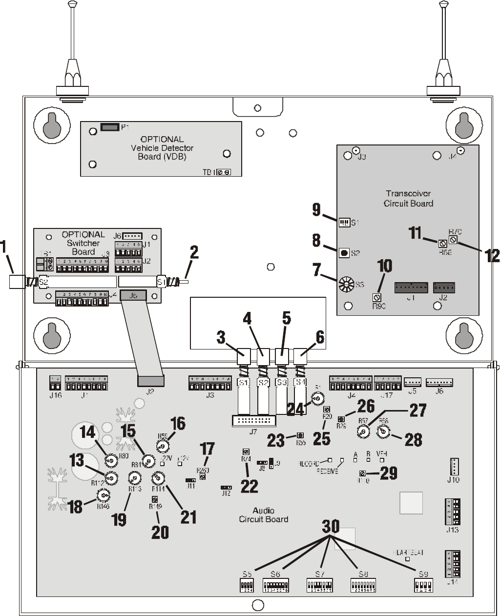
Figure 8. Base station circuit boards
21
Base Station Circuit Board Adjustments
1. Wired backup system switch – S2
2. DM2 select switch – S1
3. Record message switch – S1
4. Message repeater ON/OFF switch – S2
5. Speed team switch – S3
6. Vehicle detector override switch – S4
7. Channel selector – S3
8. System status switch – S2
9. System configuration switch – S1
10. Squelch adjustment – R90
11. “A” sidetone level – R56
12. “B” sidetone level – R70
13. Ceiling speaker “A” channel volume control – R112
14. Ceiling speaker vehicle present tone volume control –
R83
15. Ceiling speaker inbound volume control – R84
16. Outside speaker volume control – R59
17. Line out level adjustment – R260
18. VAA level adjustment – R146
19. Outside speaker message volume control – R113
20. Transmit message volume control – R149
21. Ceiling speaker message volume control – R114
22. Inbound audio level adjustment – R74
23. VAA attenuation level adjustment – R55
24. Ceiling speaker “B” dual volume control – R1
25. Line in level adjustment – R20
26. Deviation adjustment – R29
27. “B” dual audio level adjustment – R57
28. Ceiling speaker “B” volume control – R58
29. Vehicle present tone level adjustment – R110
30. System configuration switches – S5, S6,
S7, S8, S9
22
VI. SPECIFICATIONS
Base Station
Voltage input 16VAC ±2.5V
AC current input 2.5A maximum
Audio distortion 5% maximum level
Outside speaker output 3 watts RMS into 8 ohms
Ceiling speaker power 3 watts RMS into 8 ohms
Controls/Switches 2-position vehicle detector switch (Normal –
Override/Reset)
2-position “Speed Team” ON/OFF switch
2-position “Message Repeater” ON/OFF switch
1-position “Record” switch
4-position VAA and noise reduction DIP
switch
4-position RS485 bias/term DIP switch
8-position DIP switches (3 ea)
Outside speaker volume control
Outside speaker Hi-Lo volume jumper
“A” sidetone
“B” sidetone
Inbound volume control
VAA level control
Ceiling speaker volume control
Transmit message volume control
Vehicle present tone volume control
TX/RX frequency Receive - 926.064MHz – 927.864MHz
Transmit - 902.136MHz – 903.936MHz
Dimensions 8.2”H x 14.2”W x 3.5”D (208 mm x 361 mm x 89
mm)
Weight 6.5 lbs (2.95 kg) maximum
HS500 Headset COMMUNICATOR®
Battery type 3.6V Lithium ion
Battery life 10 hours (typical)
Battery operating temperature 32oF − 104oF (0oC − 45oC)
RF frequency Receive - 902.136MHz – 903.936MHz
Transmit - 926.064MHz – 927.864MHz
Weight 4.7 oz (.133 kg) with battery
Controls Power ON/OFF button
Volume-up button
Volume-down button
“A1” button
“A2” button
“B” button
Indicator Dual-color LED (red/green)
AC40 Battery Charger
Voltage input 16.5VAC
Number of charging ports 4
Number of storage ports 6
Charging time 2 hrs maximum
Dimensions 7.6” x 4.6” x 2.6” (193mm x 117mm x 66mm)
Weight 1.5 lb (.68 kg)
Indicators 4 red, 4 green, 4 yellow LEDs

23
VII. OPTIONAL EQUIPMENT
Equipment Model Number
Headset COMMUNICATOR® HS500
Battery for HS500 BAT40
Headset Earmuff No model number
Ceiling Speaker MM100
Ultrasonic Vehicle Detector DU3
Vehicle Detector Board VDB101A
Vehicle Detector Loop (underground) VDL100
Message Repeater MR300
Remote Display R30
Low-Profile Speaker SP2500LP
Microphone DM3
Mode Switch (dual lane) MS1000
Switcher Circuit Board No model number
Extended Range Antenna ANT10
VIII. FCC NOTICE
HME wireless radio frequency systems are type-accepted in the United
States under Part 90 of the Federal Communications Commission (FCC)
Code of Federal Regulations, and type-approved in Canada by Industry
and Science Canada. Because licensing depends on the system’s
application, it is the user’s responsibility to apply for a license
from the FCC in the U.S. and its possessions, or from Industry and
Science Canada in Canada and its territories. Licensing
requirements vary from country to country. Contact your local
licensing agency for specific requirements.
This device complies with Part 15 of the FCC rules. Operation is
subject to the following two conditions: (1) This device may not
cause harmful interference, and (2) This device must accept any
interference received, including interference that may cause
undesired operation.
NOTE: This equipment has been tested and found to comply with the
limits for a Class A digital device, pursuant to Part 15 of the FCC
rules. These limits are designed to provide reasonable protection
against harmful interference when the equipment is operated in a
commercial environment. This equipment generates, uses and can
radiate radio frequency energy and, if not installed and used in
accordance with the instruction manual, may cause harmful
interference to radio communication. Operation of this equipment in
a residential area is likely to cause harmful interference, in which
case the user will be required to correct the interference at his
own expense.
Changes or modifications not expressly approved by HM Electronics,
Inc. could void the users authority to operate this equipment.