HOLUX Technology CAD01 Cadence/ Speed Sensor User Manual ANT CAD SPD UM
HOLUX Technology, Inc Cadence/ Speed Sensor ANT CAD SPD UM
users manual
ANT+ 2.4G Wireless
Cadence / Speed Sensor
Cadence/Speed
User Manual
ver: 1.0
Holux Technology
www.holux.com
1
Content
Content.......................................................................................................................................................1
Cadence Sensor.........................................................................................................................................2
Installing Cadence Sensor...................................................................................................................2
Replacing the Battery of Cadence Sensor ..........................................................................................4
Cadence Spec.....................................................................................................................................5
Speed Sensor.............................................................................................................................................6
Installing Speed Sensor.......................................................................................................................6
Replacing the Battery of Speed Sensor ..............................................................................................8
Speed Spec. ........................................................................................................................................9
Wireless Link- GPSport 260 .....................................................................................................................10
Activate Wireless Link .......................................................................................................................10
Scan Sensor......................................................................................................................................10
Connect and Detect...........................................................................................................................10
2
Cadence Sensor
Cadence is the number of revolutions of the crank set per minute for cyclists.
Installing Cadence Sensor
The cadence comes in two parts, the cadence sensor itself and the magnet.
Place the sensor on the chain stay. Rotate the crank to make sure the sensor will not touch the
rotating crank. If the sensor touches the crank, move the sensor slightly upwards. Use the cable ties
to secure the cadence sensor.
Place the magnet on the crank. Use two cable ties to secure the magnet.
The cadence sensor and the magnet should pass facing each other with no more than 25 millimeters
between the two to transmit accurate data.
The details please reference for below:
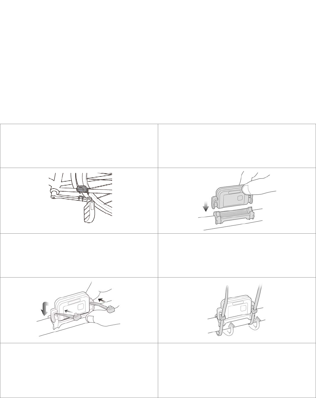
The cadence comes in two parts, the cadence
sensor itself and the magnet.
The cadence sensor should be placed on the chain
stay, and the magnet on the crank.
Place the rubber pad on the chain stay.
Place the cadence sensor on the rubber pad.
Thread the two included cable ties (thicker ones)
through the cadence sensor. Wind the cable ties to
secure the cadence sensor onto the chain stay.
DO NOT pull the cable ties yet now. Leave the
cable ties loose enough to be adjusted. The cable
ties should be fixed only when the magnet is fixed.
Continue to next step to fix the magnet.
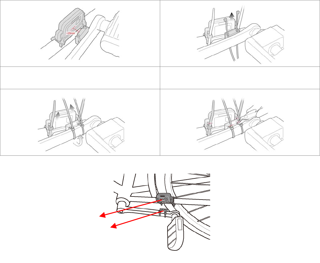
Place the magnet on the inner side of the crank.
Make sure the cadence sensor and the magnet
pass facing each other with no more than 25
millimeters between the two.
Thread and wind the included two cable ties
(thinner ones) to secure the magnet onto the crank.
Once the rotation is assured and the position of the
two is fixed, pull the cable ties to secure the
magnet.
3
Pull the cable ties to fix the cadence sensor and the
magnet.
Trim the cable ties if they hinder the rotation.
Note: There is a power button on the surface of the cadence sensor. Do not push it unless you want to
reset it.
Cadence Sensor
Magnet

4
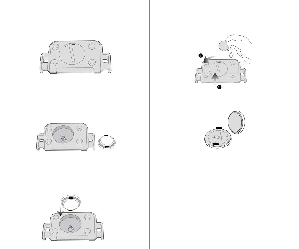
Replacing the Battery of Cadence Sensor
When the battery of the cadence sensor is drained, you can replace the battery by yourself. The coin cell
battery cadence sensor is CR2032.
Place the cadence sensor with the coin cell lid
facing up
Use a coin and align it with the groove of the lid.
Twist the lid counter-clockwise until it is loose
enough to be lifted from the edge.
Remove the lid Replace the battery with positive side facing the lid.
Restore the lid by using a coin to twist it until it is
into place.

5
Cadence Spec.
Dimension Cadence: 63.5X32.2X12.9mm
Magnet: 26.0x20.0x10.0mm
Memory RAM: 768B
ROM: 16KB Flash
Wireless Built-in 2.4GHz wireless
Support ANT+ Sport Protocol
1 Mbps on-air date rate
GFSK modulation
2.4G ISM band, 1 Mhz frequency resolution, 78 RF channels
Up to 0 dBm output power
Transmission distance: 6-7m (Max)
Battery CR2032
Active voltage: 2-3V
Active average power consumption: 3.7mA
Sleep average power consumption: 3.9uA
Environment
temperature
Operation: -10 ~ 60℃℃
Storage: -20 ~ 70 ℃℃
6
Speed Sensor
Speed is the number of distance of the wheels set per minute for cyclists.
Installing Speed Sensor
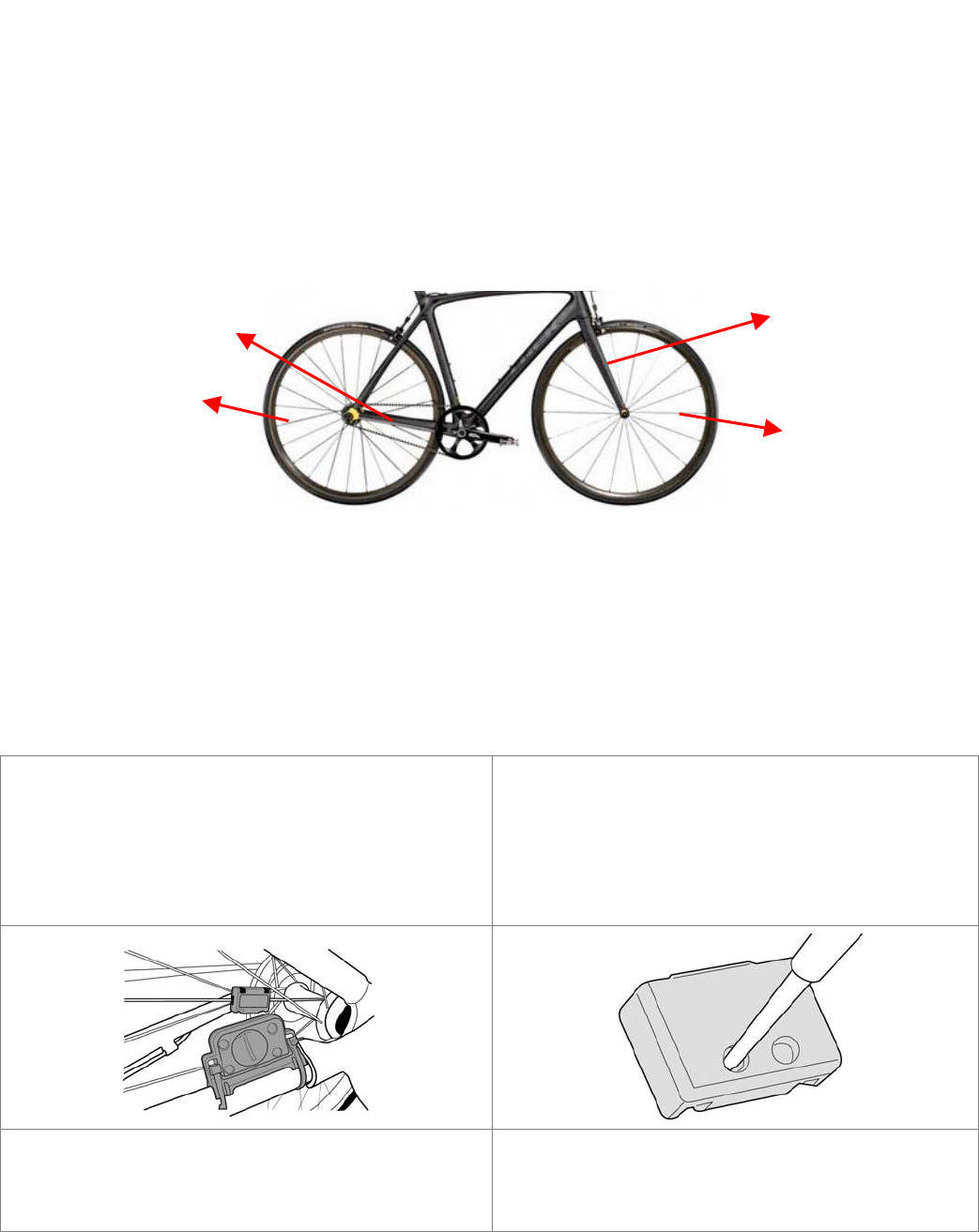
The speed senor comes in two parts, the speed sensor itself and the magnet. You can choose to
install the speed sensor/magnet to the fork/front wheel spoke or the chain stay/back wheel spoke of
your bike as long as the magnet is at the same level of the speed sensor and the spacing of the two
should not exceed 25 millimeters
Use two cable ties to secure the speed sensor to the fork or chain stay of your bike.
Attach the magnet to the wheel spoke. The magnet must be facing the speed sensor. For the spoke
is too thin for the magnet to attach by cable ties, users should tighten the magnet screw instead of
using cable ties.
The magnet and speed sensor should pass facing each other with no more than 25 millimeters
between the two to transmit accurate data.
The details please reference for below:
The speed sensor comes in two parts, the speed
sensor itself and the magnet.
The speed sensor should be placed on the chain
stay and the magnet on the rear wheel spoke, the
two should pass facing each other.
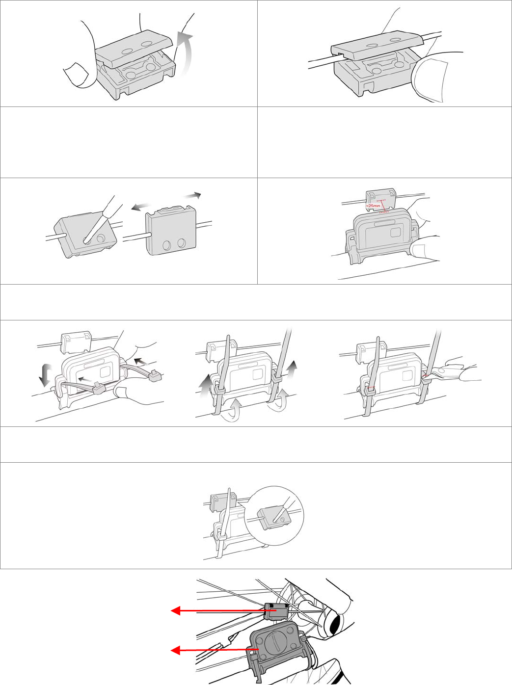
Unscrew the magnet to open it.
Open the magnet without separating the cases
apart.
Attach the magnet to a spoke of the rear wheel by
threading the spoke through the U-shaped
indentation on both sides of the magnet.
Spoke
Spoke
Fork Fork
7
Close the magnet and screw it.
Do NOT secure the screw yet, leave the magnet
loose enough to be adjusted until the speed sensor
is fixed. Continue to fix the speed sensor.
Place the speed sensor on the inner side of a chain
stay. Make sure the speed sensor and the magnet
should pass facing each other with no more than
25 millimeters between the two.
Thread and wind the included two cable ties (thicker ones) to secure the speed sensor onto the chain
stay. Trim the cable ties if they hinder the rotation
Secure the speed sensor to make sure it is firmly attached to the spoke without moving upward or
downward while cycling.
Speed Sensor
Magnet
8
Note: There is a power button on the surface of the speed sensor. Do not push it unless you want to reset
it.
Replacing the Battery of Speed Sensor
When the battery of the speed sensor is drained, you can replace the battery by yourself. The coin cell
battery speed sensor is CR2032.
Place the cadence sensor with the coin cell lid
facing up
Use a coin and align it with the groove of the lid.
Twist the lid counter-clockwise until it is loose
enough to be lifted from the edge.
Remove the lid Replace the battery with positive side facing the lid.
Restore the lid by using a coin to twist it until it is
into place.

9
Speed Spec.
Dimension Speed: 63.5X32.2X12.9mm
Magnet: 26.0x20.0x10.0mm
Memory RAM: 768B
ROM: 16KB Flash
Wireless Built-in 2.4GHz wireless
Support ANT+ Sport Protocol
1 Mbps on-air date rate
GFSK modulation
2.4G ISM band, 1 Mhz frequency resolution, 78 RF channels
Up to 0 dBm output power
Transmission distance: 6-7m (Max)
Battery CR2032
Active voltage: 2-3V
Active average power consumption: 3.7mA
Sleep average power consumption: 3.9uA
Environment
temperature
Operation: -10 ~ 60℃℃
Storage: -20 ~ 70 ℃℃
10
Wireless Link- GPSport 260
The GPSport 260 Pro is using ANT+ to collect and transfer sensor data. The three sport sensors
supported are HRM, speed sensor and cadence.
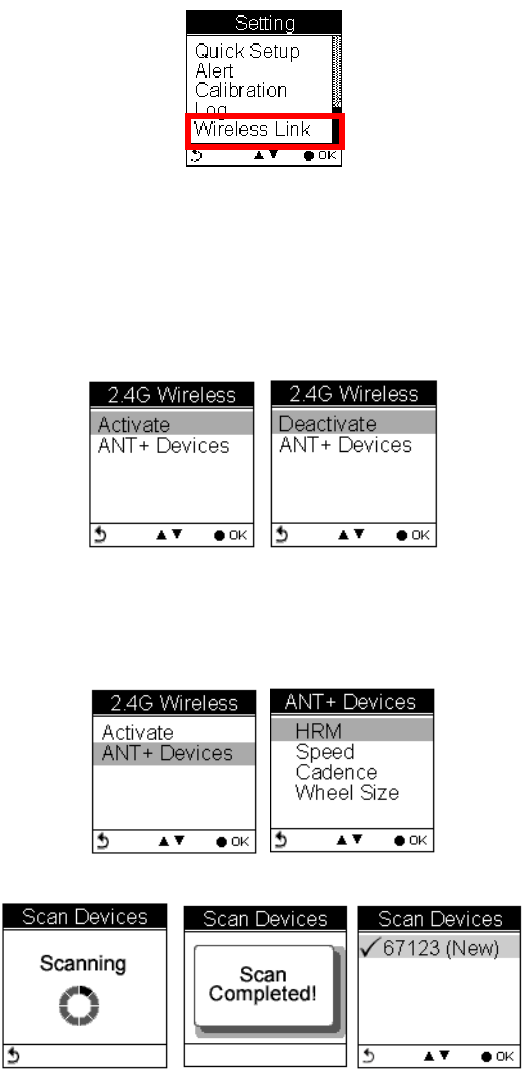
Activate Wireless Link
Users have to activate the GPSport 260 Pro wireless link before they connect the GPSport 260 Pro with
sport sensors. If the wireless link is not yet activated, the setting menu displays “Activate” for selection,
otherwise, “Deactivate” is displayed when the device is active.
Scan Sensor
Select ANT+ Devices to select the sport sensor to connect.
The device will start scanning devices nearby. When completed, scanned devices are listed.
Connect and Detect
Move the Up/Down arrow to select the sensor to connect.
A warning message prompts to remind users to make sure the selected sensor is properly installed, for
example, HRM should be well-strapped to your chest so that the GPSport 260 Pro can detect without
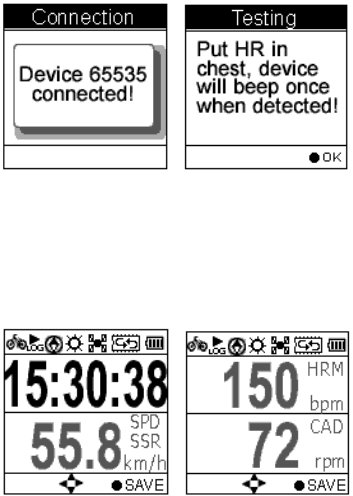
11
failure.
The GPSport 260 Pro can connect up to 3 sensors of different kinds at a time, namely, one HRM, one
Speed sensor, and one Cadence sensor can be connected concurrently. If a sport device is detected, a
screen appears as shown.
12
"FEDERAL COMMUNICATIONS COMMISSION INTERFERENCE STATEMENT
This equipment has been tested and found to comply with the limits for a Class B digital
device, pursuant to Part 15 of the FCC Rules. These limits are designed to provide reasonable
protection against harmful interference in a residential installation. This equipment generates,
uses and can radiate radio frequency energy and, if not installed and used in accordance with the
instructions, may cause harmful interference to radio communications. However, there is no
guarantee that interference will not occur in a particular installation. If this equipment does cause
harmful interference to radio or television reception, which can be determined by turning the
equipment off and on, the user is encouraged to try to correct the interference by one or more of
the following measures:
--Reorient or relocate the receiving antenna.
--Increase the separation between the equipment and receiver.
--Connect the equipment into an outlet on a circuit different from that to which the receiver is
connected.
--Consult the dealer or an experienced radio/TV technician for help."
"RF exposure warning
·This equipment must be installed and operated in accordance with provided instructions and the
antenna(s) used for this transmitter must be installed to provide a separation distance of at least
20 cm from all persons and must not be co-located or operating in conjunction with any other
antenna or transmitter. End-users and installers must be provide with antenna installation
instructions and transmitter operating conditions for satisfying RF exposure compliance. "
"CAUTION:
Any changes or modifications not expressly approved by the grantee of this device could void
the user's authority to operate the equipment."
This device complies with Part 15 of the FCC Rules. Operation is subject to the following two
conditions: (1) this device may not cause harmful interference and (2) this device must accept any
interference received, including interference that may cause undesired operation.