HOLUX Technology DF100 Hypo-Vigilance / Fatigue Detector /VigilanceSense / BodySensing User Manual DFD100 UM EN 111129
HOLUX Technology, Inc Hypo-Vigilance / Fatigue Detector /VigilanceSense / BodySensing DFD100 UM EN 111129
UserManual.wiki
>
HOLUX Technology
>
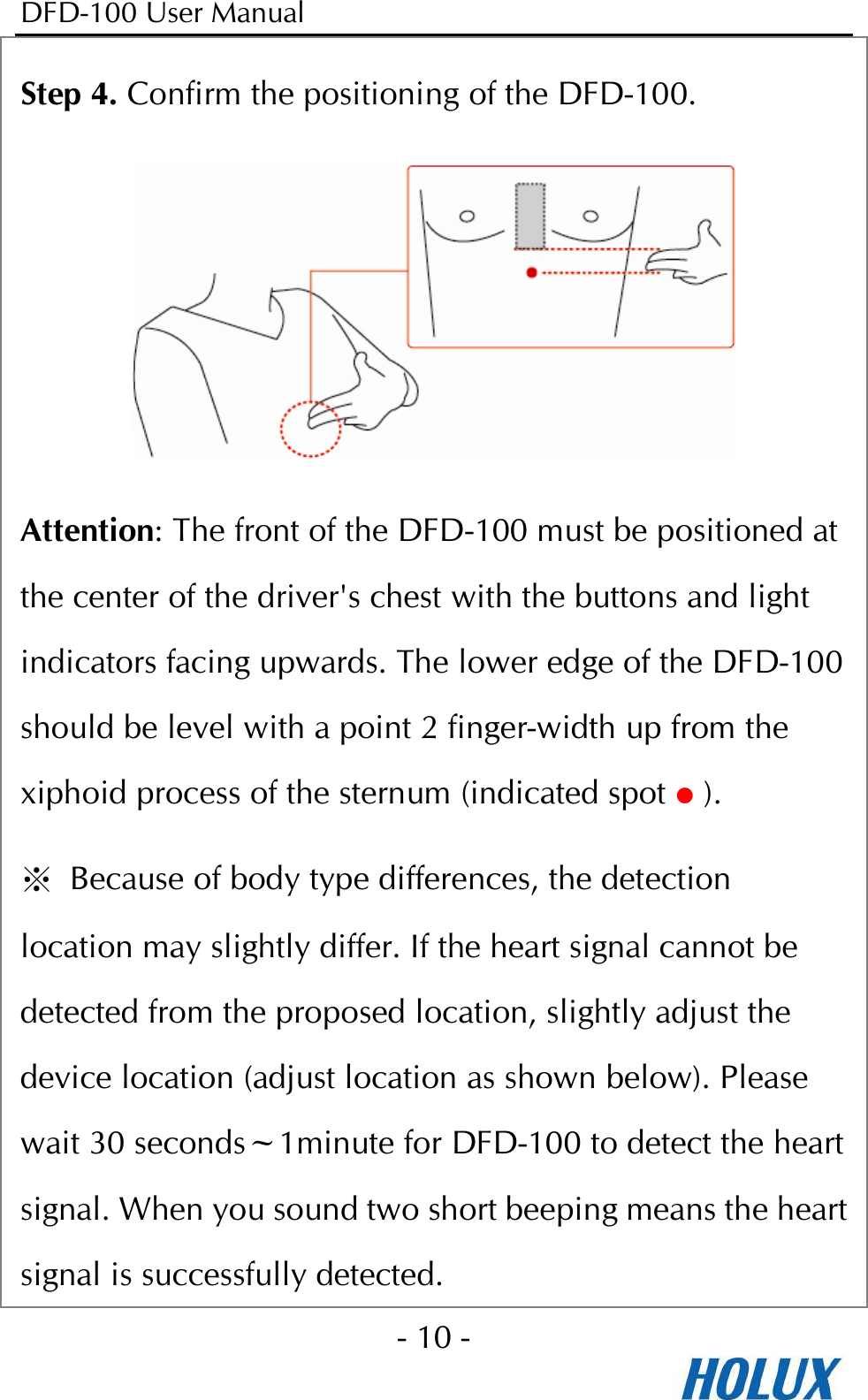
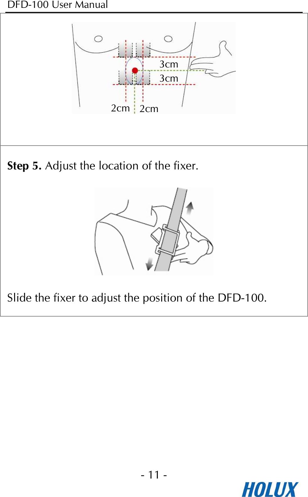
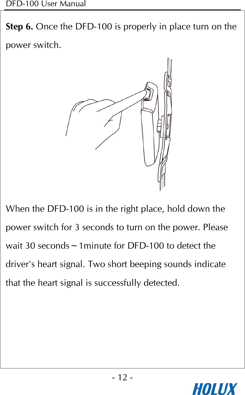
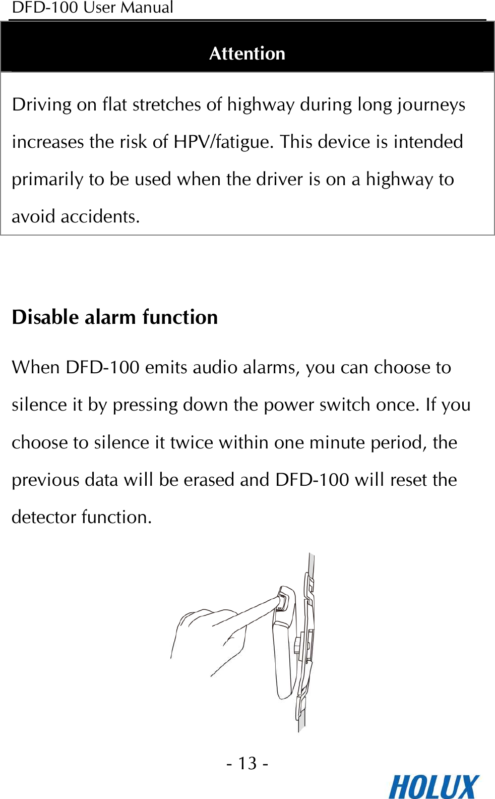
DF100 User Manual
user manual
Navigation menu
Upload a User Manual
Namespaces
Wiki Guide
HTML
PDF
Info
Views
User Manual
Discussion / Help
Navigation