HOLUX Technology TRACKER005 Multi-Function Wrist Worn GPS Tracking Device User Manual GR530XX User Manual Rev2
HOLUX Technology, Inc Multi-Function Wrist Worn GPS Tracking Device GR530XX User Manual Rev2
UserManual.wiki
>
HOLUX Technology
>
TRACKER005 User Manual
Users Manual Revision 3
Navigation menu
Upload a User Manual
Namespaces
Wiki Guide
HTML
PDF
Info
Views
User Manual
Discussion / Help
Navigation
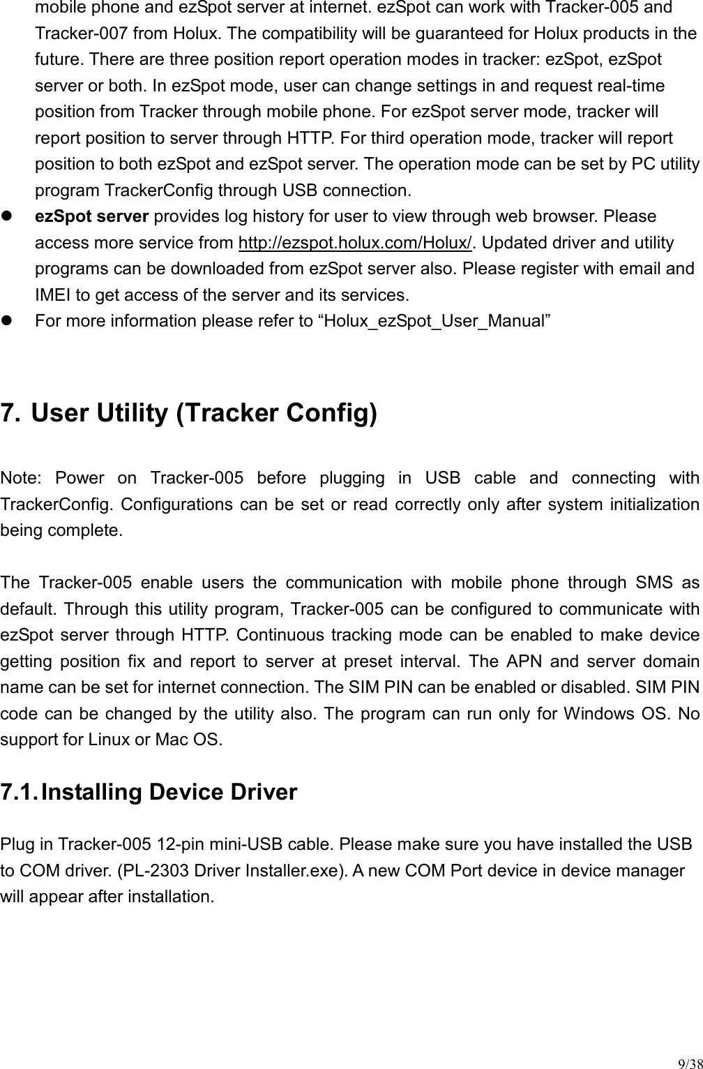
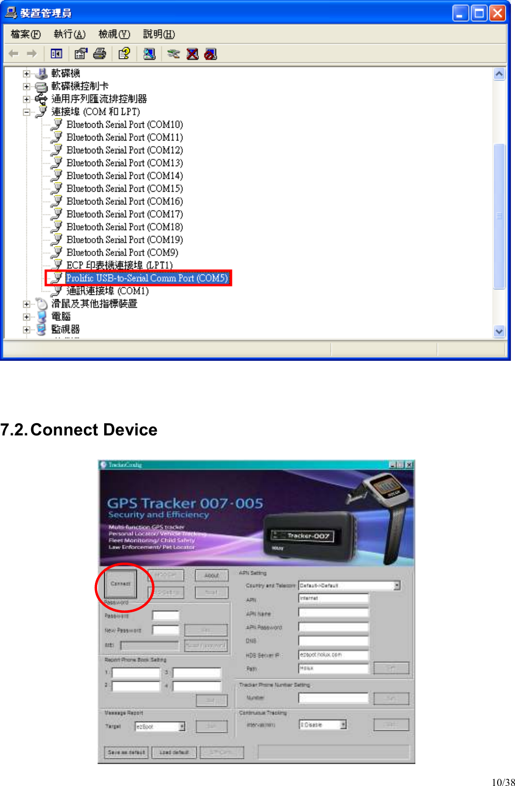
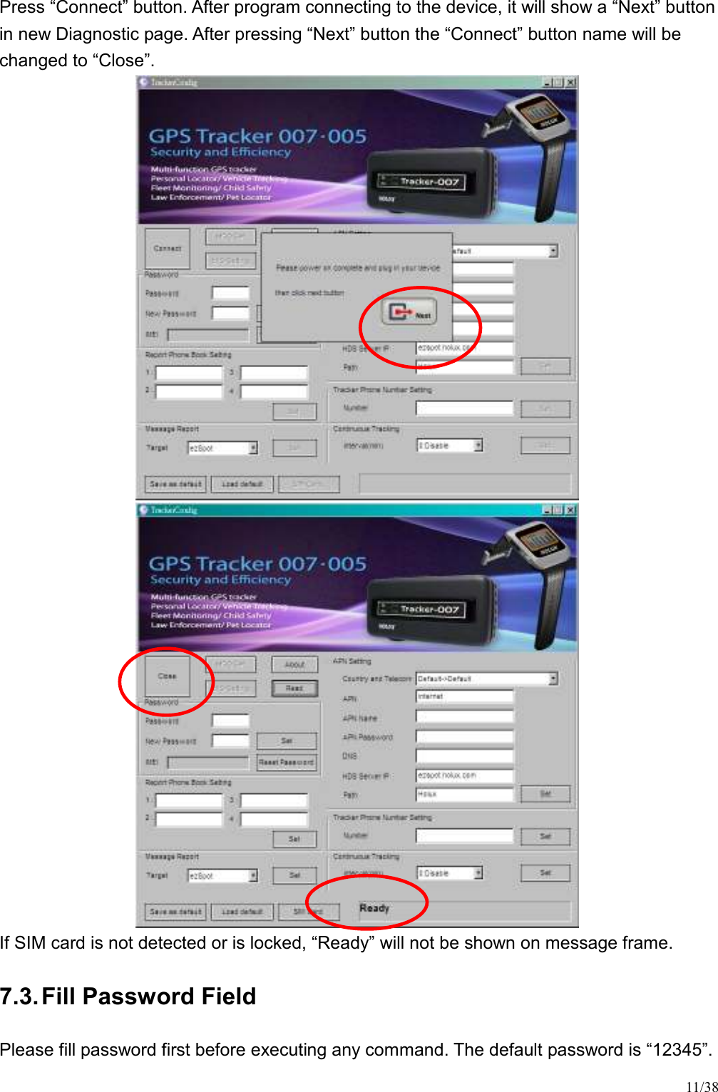
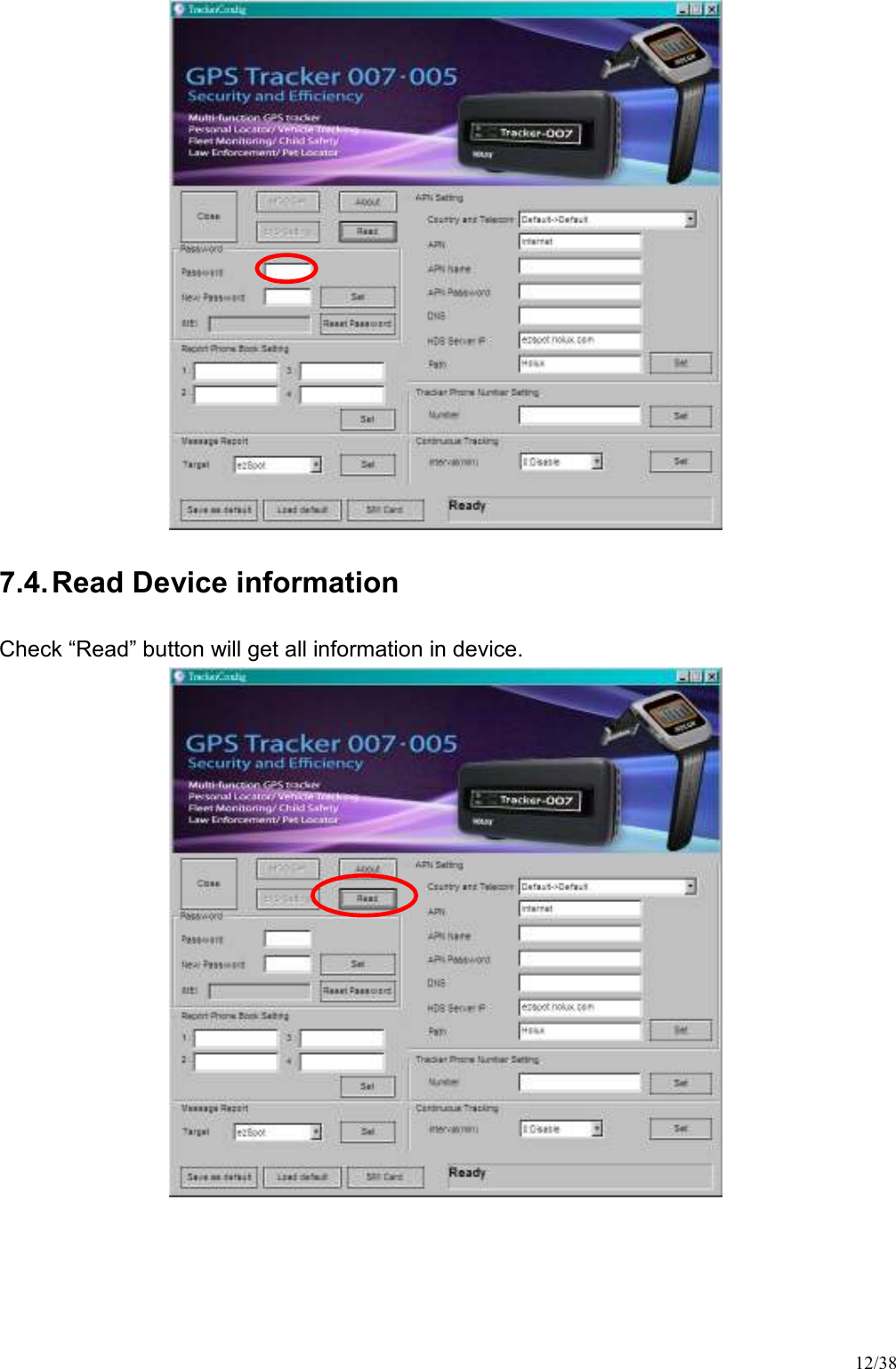
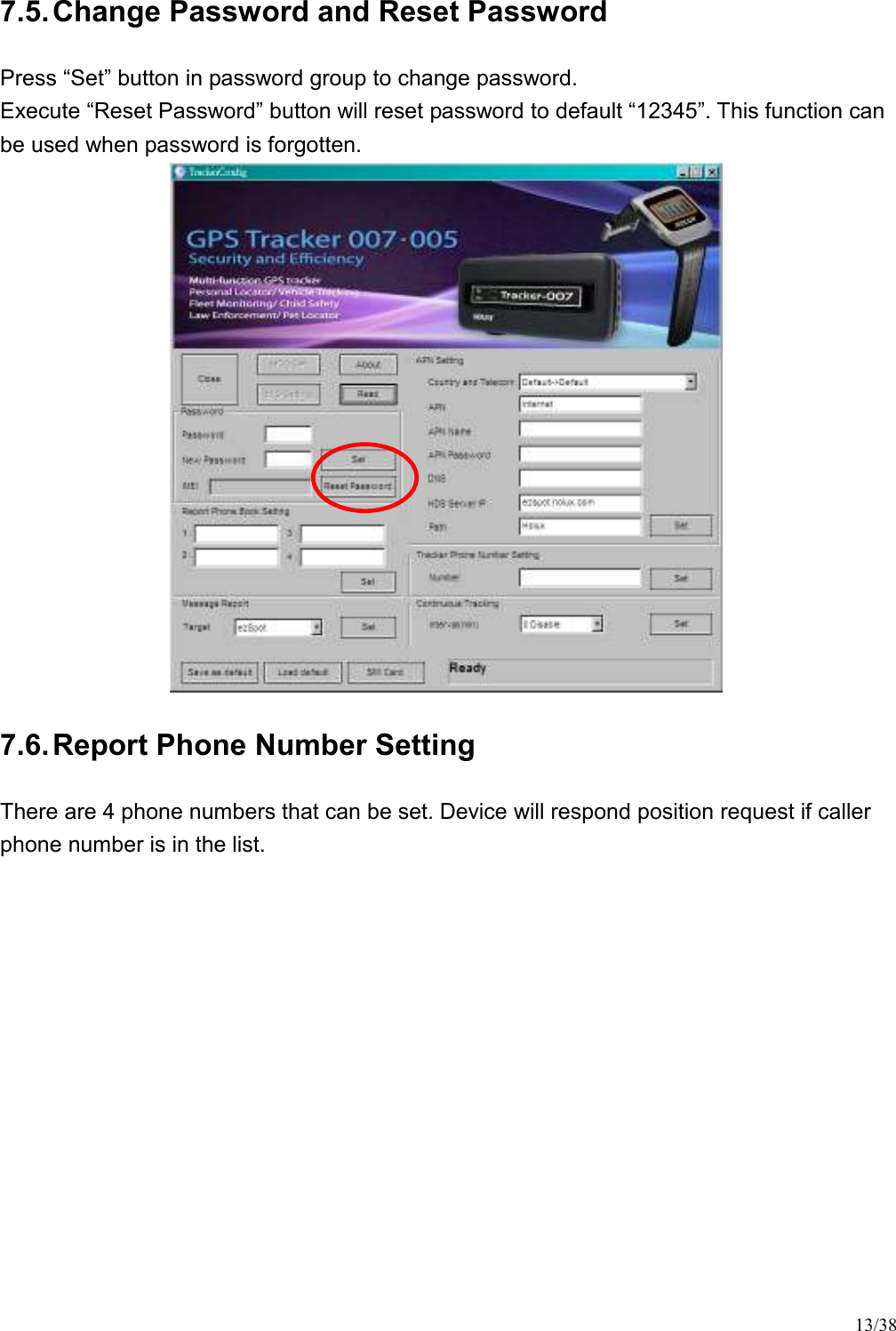
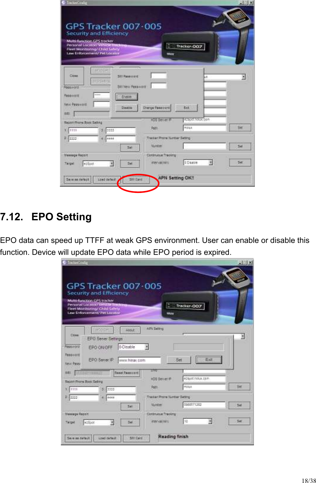
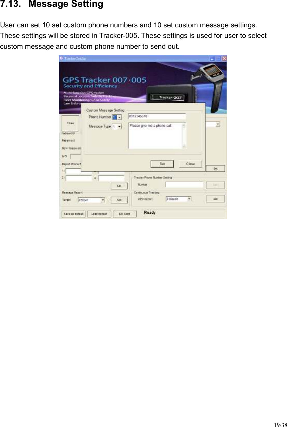
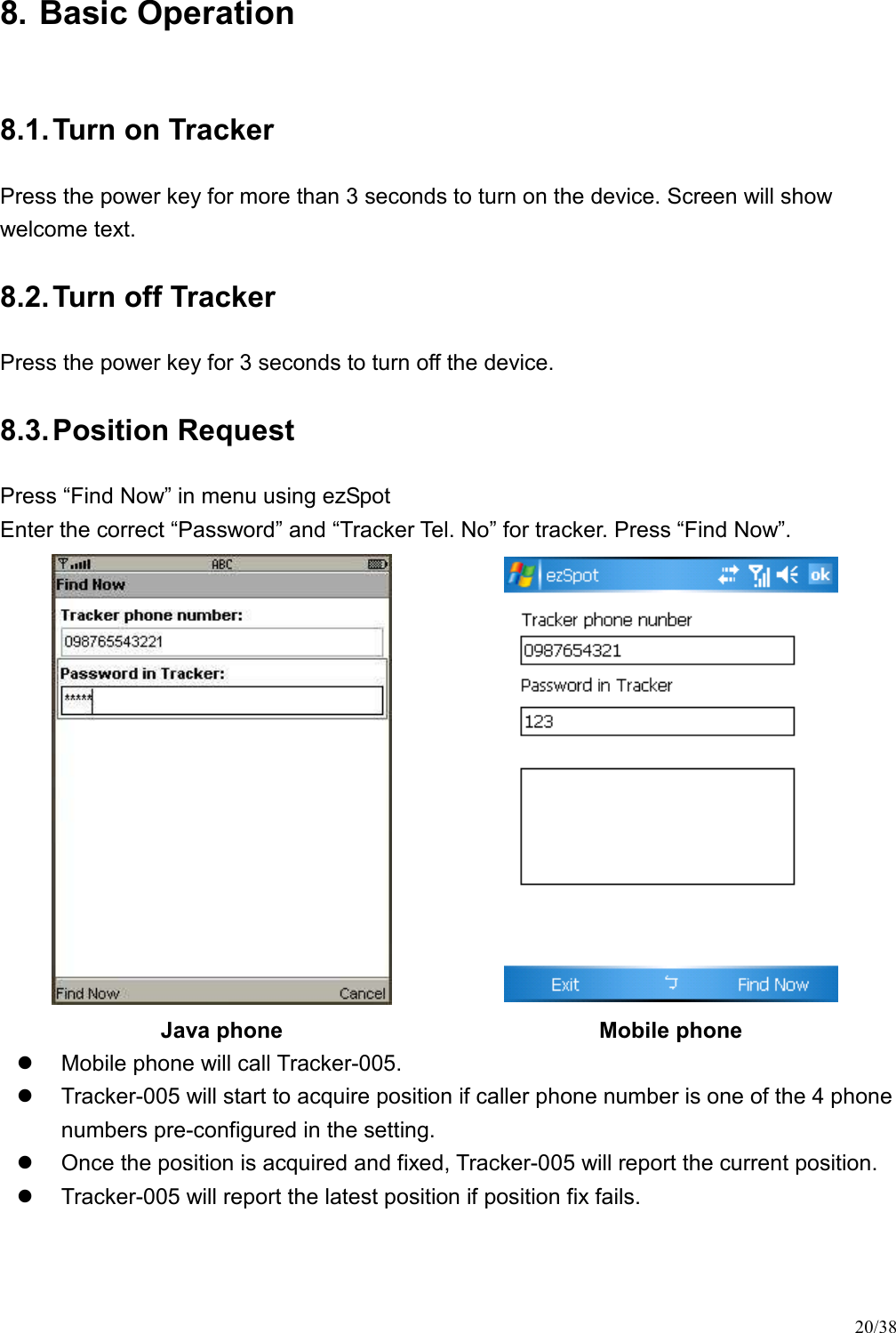
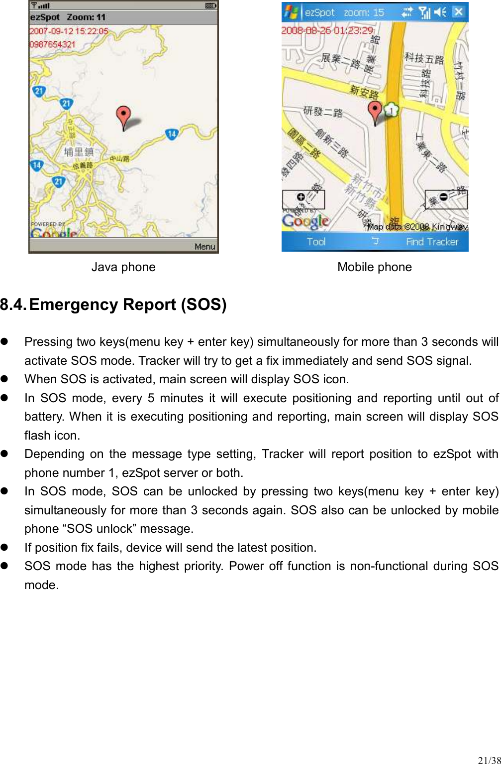
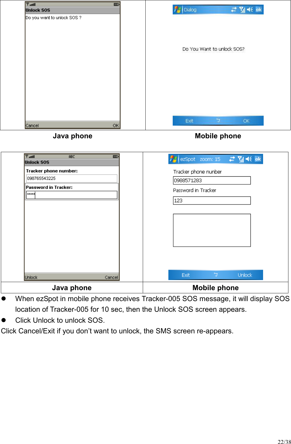
![14/38 7.7. Message Report Target The function can be used to set parameter for report target. Tracker-005 can report position to ezSpot in mobile phone or ezSpot server [ezSpot]: Tracker-005 will send position to ezSpot through SMS. [ezSpot Server]: Tracker-005 will send position to ezSpot server (or MDS) through HTTP. [both]: Tracker-005 will send position to ezSpot through SMS and ezSpot server through HTTP. There are two type of “Message Report Target” : (1) Set“Report Target” to “ezSpot”: On SOS mode: Tracker-005 sends its position back to Phone Number via short message every 5 minutes. On RING mode: if the phone number of the caller is one of the preset phone numbers, then Tracker-005 will send its position back to the caller via short message, otherwise it will not return any message to the caller. (2) Set“Report Target” to “ezSpot Server”: On SOSmode: Tracker-005 sends its position back to ezSpot Server via HTTP every 5 minutes. On RING mode: if the phone number of the caller is one of the preset phone numbers, then, Tracker-005 will send its position back to the ezSpot server via HTTP. Otherwise it will not return any information to the ezSpot server. (3) Set “Report Target” to “both”: On SOS mode: Tracker-005 sends its position back to Phone Number via short message](https://usermanual.wiki/HOLUX-Technology/TRACKER005/User-Guide-1035046-Page-14.png)
![15/38 and its position back to ezSpot Server via HTTP every 5 minutes. On RING mode: if the phone number of the caller is one of the preset phone number, then Tracker-005 will send its position back to the caller via short message, and send its position back to the ezSpot server via HTTP, otherwise it will not return any message to the caller. 7.8. APN Setting This item is to get and set MDS server setting. [APN]: This indicates Access Point Name [APN User Name]: This indicates the user name for APN. [APN Password]: This indicates the user password for APN. [APN DNS]: This indicates the APN domain name server. [MDS Server IP]: MDS (or ezSpot server) IP or domain name. Default is “ezspot.holux.com”. The parameters will be set automatically by selecting Country and Telecom. Default will be “internet”. Manual input changes are allowable if necessary. 1 2 3.](https://usermanual.wiki/HOLUX-Technology/TRACKER005/User-Guide-1035046-Page-15.png)
![16/38 7.9. Phone Number Setting [Number]: Number (MSISDN) is the phone number of SIM card in Tracker-005. 1 2. 1 2](https://usermanual.wiki/HOLUX-Technology/TRACKER005/User-Guide-1035046-Page-16.png)
![17/38 7.10. Continuous Tracking [Continuous tracking setting] In continuous tracking mode, Tracker-005 will report position to ezSpot server at the preset interval. [Interval (min)]: This is the duration, in minutes, for which continuous tracking needs to be done. The range is from 3 ~ 1440 minutes. If 0 is passed to the continuous tracking, it will disable continuous tracking. User can use combo box to select the interval (See red area #1), and use the “set” button to set the setting to device. (See red area #2) 7.11. SIM PIN SIM PIN can be locked or unlocked through “SIM Card” function. SIM PIN code can also be changed. It is recommended to set SIM PIN in unlock mode to prevent SIM card from entering locked state. 1 2](https://usermanual.wiki/HOLUX-Technology/TRACKER005/User-Guide-1035046-Page-17.png)
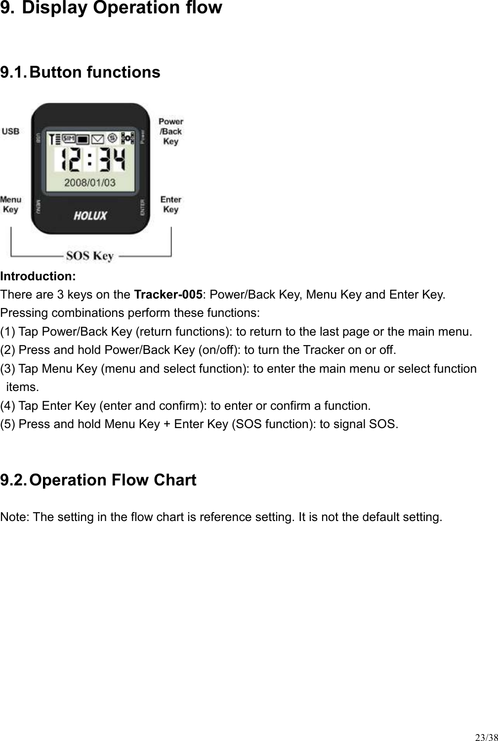
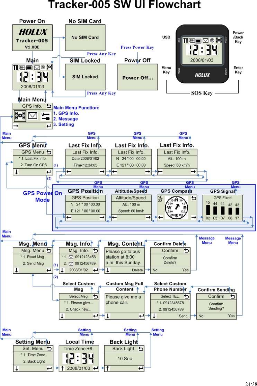
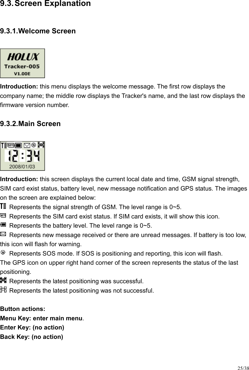
![27/38 (when there is fixed data on this device) Introduction: this screen displays the date and time of the last successful positioning. Button actions: Menu Key: Go back to the previous screen: [Last Fixed Information – Altitude/Speed]. Enter Key: Go to the next screen: [Last Fixed Information - Position]. Back Key: Go back to the GPS menu. 9.3.6. GPS - Last Fixed Information - Position (when there is no fixed data on this device) (when there is fixed data on this device) Introduction: this screen displays the position of the last successful positioning. Button actions: Menu Key: Go back to the previous screen: [Last Fixed Information – Date/Time]. Enter Key: Go to the next screen: [Last Fixed Information – Altitude/Speed]. Back Key: Go back to the GPS menu. 9.3.7. GPS - Last Fixed Information – Altitude/Speed (when there is no fixed data on this device) (when there is fixed data on this device) Introduction: this screen displays the altitude and speed of the last successful positioning. Button actions: Menu Key: Go back to the previous screen: [Last Fixed Information – Position]. Enter Key: Go to the next screen: [Last Fixed Information – Date/Time].](https://usermanual.wiki/HOLUX-Technology/TRACKER005/User-Guide-1035046-Page-27.png)
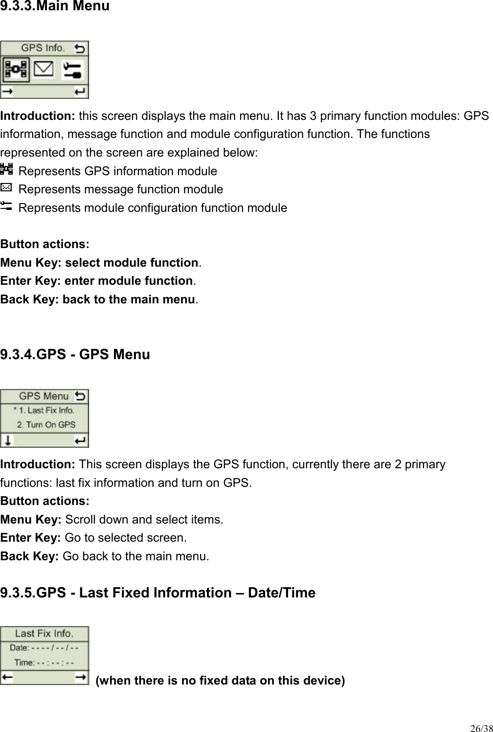
![28/38 Back Key: Go back to the GPS menu. 9.3.8. GPS - GPS Position (GPS not fixed) (GPS fixed) Introduction: this screen displays the current GPS location information. The first row displays latitude and the second row displays longitude. Button actions: Menu Key: Go back to the previous screen: [Latest GPS positioning date and time]. Enter Key: Go to the next screen: [GPS location information]. Back Key: Go to the GPS menu. 9.3.9. GPS - Altitude/Speed (GPS not fixed) (GPS fixed) Introduction: this screen displays the current GPS altitude and speed. "Altitude" represents altitude information, with meter as its unit. "Speed" represents speed information, with km/hr as its unit. Button actions: Menu Key: Go back to the previous screen: [GPS location information]. Enter Key: Go to the next screen: [direction of GPS compass]. Back Key: Go back to the GPS menu.](https://usermanual.wiki/HOLUX-Technology/TRACKER005/User-Guide-1035046-Page-28.png)
![29/38 9.3.10. GPS - Compass (GPS not fixed) (GPS fixed) Introduction: this screen displays the easy compass that displays the current forward direction. The number on the left displays the actual angle and the range of the angle is 0 ~ 359. Note: the direction information is only valid when the device is on moving condition. Button actions: Menu Key: Go back to the previous screen: [altitude and speed information for GPS]. Enter Key: Go to the next screen: [satellite signal strength for GPS]. Back Key: Go back to the GPS menu. 9.3.11. GPS - GPS Signal Strength (no GPS signal) (GPS not fixed, and not used) (GPS not fixed, but used) (GPS fixed and used)](https://usermanual.wiki/HOLUX-Technology/TRACKER005/User-Guide-1035046-Page-29.png)
![30/38 Introduction: this screen displays the current GPS satellite signal strength C/N value information, currently it displays the satellite ID numbers and values for 5 satellites with the 5 strongest C/N values. The numbers in the bottom row represent the satellite ID numbers for satellites, the bars in the middle row represent the strength of satellite signals and the higher the bar, the stronger the signal. A hollow bar represents unused satellite, a half-hollow bar shows a satellite is used but the positioning isn't successfully fixed yet and a solid bar means the satellite is being used and the current positioning is successfully fixed. The numbers on the upper row represent the C/N value of the satellite signal strength. Button actions: Menu Key: Go back to the previous screen: [GPS compass direction]. Enter Key: Go to the next screen: [the latest positioning information]. Back Key: Go back to the main menu. 9.3.12. Message – Message Menu Introduction: This screen displays messaging function, currently there are 2 primary functions: reading message and sending message. Button actions: Menu Key: Scroll down and select items. Enter Key: Go to selected screen. Back Key: Go back to the main menu. 9.3.13. Message - Message Information Introduction: this screen displays the message information including icons for read or not read and the number and date for message sender. The explanation for icons is below: : The message has not been read. : The message has been read.](https://usermanual.wiki/HOLUX-Technology/TRACKER005/User-Guide-1035046-Page-30.png)
![31/38 Button actions: Menu Key: Scroll down and select items. Enter Key: Go to the next screen: [message content]. Back Key: Go back to the previous screen: [message main menu]. 9.3.14. Message - Message Content Introduction: this screen displays the message content. Button actions: Menu Key: Scroll down and see the rest of the message content. Enter Key: Delete this message. Back Key: Go back to the previous screen: [message information]. 9.3.15. Message - Confirm Delete Introduction: This screen is used to confirm the message is deleted. Button actions: Menu Key: Select [No] to give up deleting and Go back to the previous screen: [message content]. Enter Key: Select [Yes] to confirm delete. Back Key: Go back to the previous screen: [message content]. 9.3.16. Message - Select Custom Message Introduction: Select the message content to be sent on this screen.](https://usermanual.wiki/HOLUX-Technology/TRACKER005/User-Guide-1035046-Page-31.png)
![32/38 Button actions: Menu Key: Scroll down and select items. Enter Key: Go to the next screen: [select the entire content of the default message]. Back Key: Go back to the previous screen: [main message menu]. 9.3.17. Message - Custom Message Full Content Introduction: This screen displays the entire content of the message being sent. Button actions: Menu Key: Scroll down and see the rest of the message content. Enter Key: Go to the next screen: [select default number]. Back Key: Go back to the previous screen: [select default message content]. 9.3.18. Message - Select Custom Phone Number Introduction: Select the default phone number on this screen. Button actions: Menu Key: Scroll down and select items. Enter Key: Go to the next screen: [confirm sending message]. Back Key: Go back to the previous screen: [select the entire content of the default message content]. 9.3.19. Message - Confirm Sending Introduction: This screen is used to confirm message is sent.](https://usermanual.wiki/HOLUX-Technology/TRACKER005/User-Guide-1035046-Page-32.png)
![33/38 Button actions: Menu Key: Select [No] giving up sending message and Go back to the previous screen: [select default phone number]. Enter Key: Select [Yes] to confirm message is sent. Back Key: Go back to the previous screen: [select default phone number]. 9.3.20. Setting - Setting Menu Introduction: This screen displays the setting function, currently there are 2 primary functions: time zone and back light. Button actions: Menu Key: Scroll down and select items. Enter Key: Go to selected screen. Back Key: Go back to the main menu. 9.3.21. Setting - Set Local Time Introduction: This screen is used to set local time. Button actions: Menu Key: Change time zone information (the range of time zone is: -12 ~ +13). Enter Key: Save time zone information and go to the next screen [Set Back Light Timer]. Back Key: Go back to the setting menu. Note: Default time zone is +0. 9.3.22. Setting - Set Back Light Timer](https://usermanual.wiki/HOLUX-Technology/TRACKER005/User-Guide-1035046-Page-33.png)
![34/38 Introduction: This screen is used to configure the time for the backlight to be on. Button actions: Menu Key: Change the time for the backlight to be on <provides these choices 5 seconds, 10 seconds, 15 seconds, 30 seconds and 60 seconds>. Enter Key: Save the configuration for the length of time for the backlight and go to next screen [Set Local Time]. Back Key: Go back to the setting menu. Note: Default back light is 10 sec. 9.3.23. Power Off Introduction: power off process. 10. Terminology EPO Extended Prediction Orbit, predicted ephemeris data specific for MTK chip solution.. MDS Main Data Server, device will send position information to server through HTTP message MTK Mediatek Inc. SMS Short Message Service TTFF Time to First Fix ezSpot Service ezSpot Service is a multi-functional Holux tracker system which includes ezSpot in mobile phone and ezSpot server at internet. ezSpot ezSpot is the tracking service program running in Java and Windows Mobiles phones. ezSpot server ezSpot server is demo tracking service web site at Holux. Domain name http://ezspot.holux.com/Holux](https://usermanual.wiki/HOLUX-Technology/TRACKER005/User-Guide-1035046-Page-34.png)