HON HAI PRECISION IND CSE300APK9 Cisco Edge 300 User Manual OL 24909
HON HAI Precision Ind. Co., Ltd. Cisco Edge 300 OL 24909
manual

Americas Headquarters:
Cisco Systems, Inc., 170 West Tasman Drive, San Jose, CA 95134-1706 USA
Cisco Edge 300 Series Switch Installation Guide
•About this Guide, page 1
•Box Contents, page 2
•Overview, page 3
•Installing the Switch, page 6
•Powering on the Switch, page 15
•Restoring the Factory Settings, page 15
•Technical Specifications, page 15
•Obtaining Documentation and Submitting a Service Request, page 16
About this Guide
This guide describes how to install the Cisco Edge 300 series switch on a wall or desktop and describes
the LEDs and ports.
For configuration information, see the Cisco Edge 300 series switch documentation on Cisco.com. For
system requirements, important notes, limitations, open and resolved bugs, and documentation updates,
see the release notes on Cisco.com.
2
Cisco Edge 300 Series Switch Installation Guide
OL-24909-01
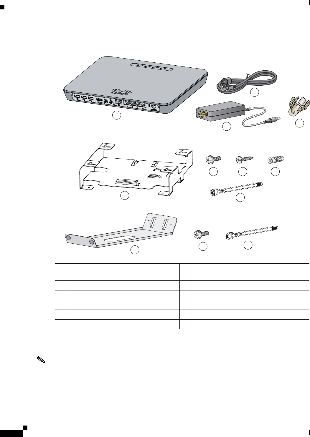
Box Contents
Box Contents
Note Verify that you have received these items. If any item is missing or damaged, contact your Cisco
representative or reseller.
1Cisco Edge 300 series switch 7Four M3.5 x 16-mm Phillips head tapping
screws1
2Power adapter 8Four plastic drywall anchors1
3Power cord 9Cable tie1, 2
4Power cord retainer1, 2
1. These parts are included in the wall-mount kit (ACC-E300-WALL).
2. These parts are included in the desktop kit (ACC-E300-DESK).
10 Desktop bracket2
5Wall-mount bracket111 Two M3.0 x 6-mm Phillips pan head screws2
6Four M3.0 x 6-mm Phillips pan head screws1
1
2
3
4
5
6 7 8
9
10 11 9
3
Cisco Edge 300 Series Switch Installation Guide
OL-24909-01
Overview
Overview
Figure 1 Cisco Edge 300 Series Switch — Front
Figure 2 Cisco Edge 300 Series Switch — Left
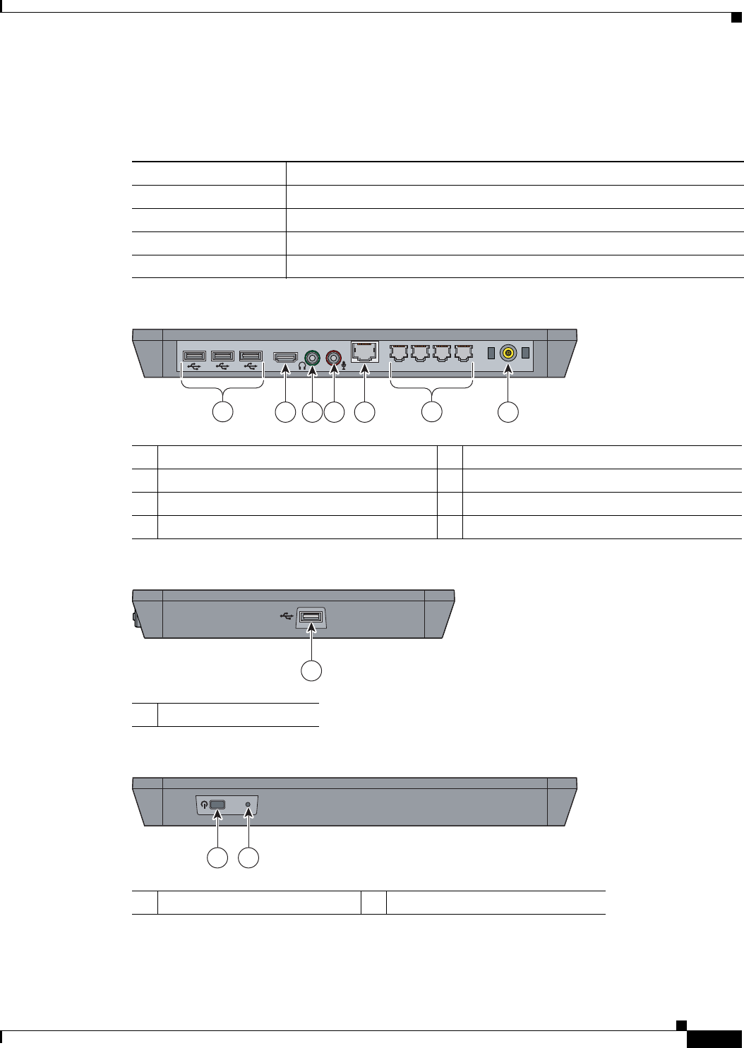
Figure 3 Cisco Edge 300 Series Switch — Rear
Table 1 Cisco Edge 300 Series Models
Model Description
CS-E300-AP-K9 Cisco Edge 300 series switch with WiFi and Bluetooth
CS-E300-K9 Cisco Edge 300 series switch
HS-E300-AP-K9 HSJC/Cisco Edge 300 series switch with WiFi and Bluetooth
HS-E300-K9 HSJC/Cisco Edge 300 series switch
1USB ports 5Gigabit Ethernet (uplink) port
2HDMI port 6Ethernet (downlink) ports
3Audio out port 7Power
4Audio in port
POWER
1234
GE
HDMI
255417
2
134 5 7
6
1USB port
255418
1
1Power button 2Reset button
255419
RESET
1 2

4
Cisco Edge 300 Series Switch Installation Guide
OL-24909-01
Overview
Port Descriptions
USB
There are four USB 2.0 Type-A ports. Each USB port can provide up to 5 W of power to a connected
device.
You can connect a wired USB keyboard and mouse, a wireless USB receiver for a keyboard and mouse,
a USB camera, or a USB thumb drive.
HDMI
The HDMI port supports high-definition video output at 720p or 1080p.
Audio In
You can connect a microphone that uses a 3.5 mm connector.
Audio Out
You can connect headphones or external speakers that use a 3.5 mm connector.
Gigabit Ethernet
The Gigabit Ethernet uplink port provides a 10/100/1000 Mb/s connection to a Catalyst 2000 or
Catalyst 3000 series switch.
Ethernet
The Fast Ethernet ports provide 10/100 Mb/s connections to computers or other devices.
Wireless Features
WiFi
Supports 802.11b/g/n wireless clients.
Bluetooth
Supports Human Interaction Design Protocol (HIDP) for remote control or input devices.
5
Cisco Edge 300 Series Switch Installation Guide
OL-24909-01
Overview
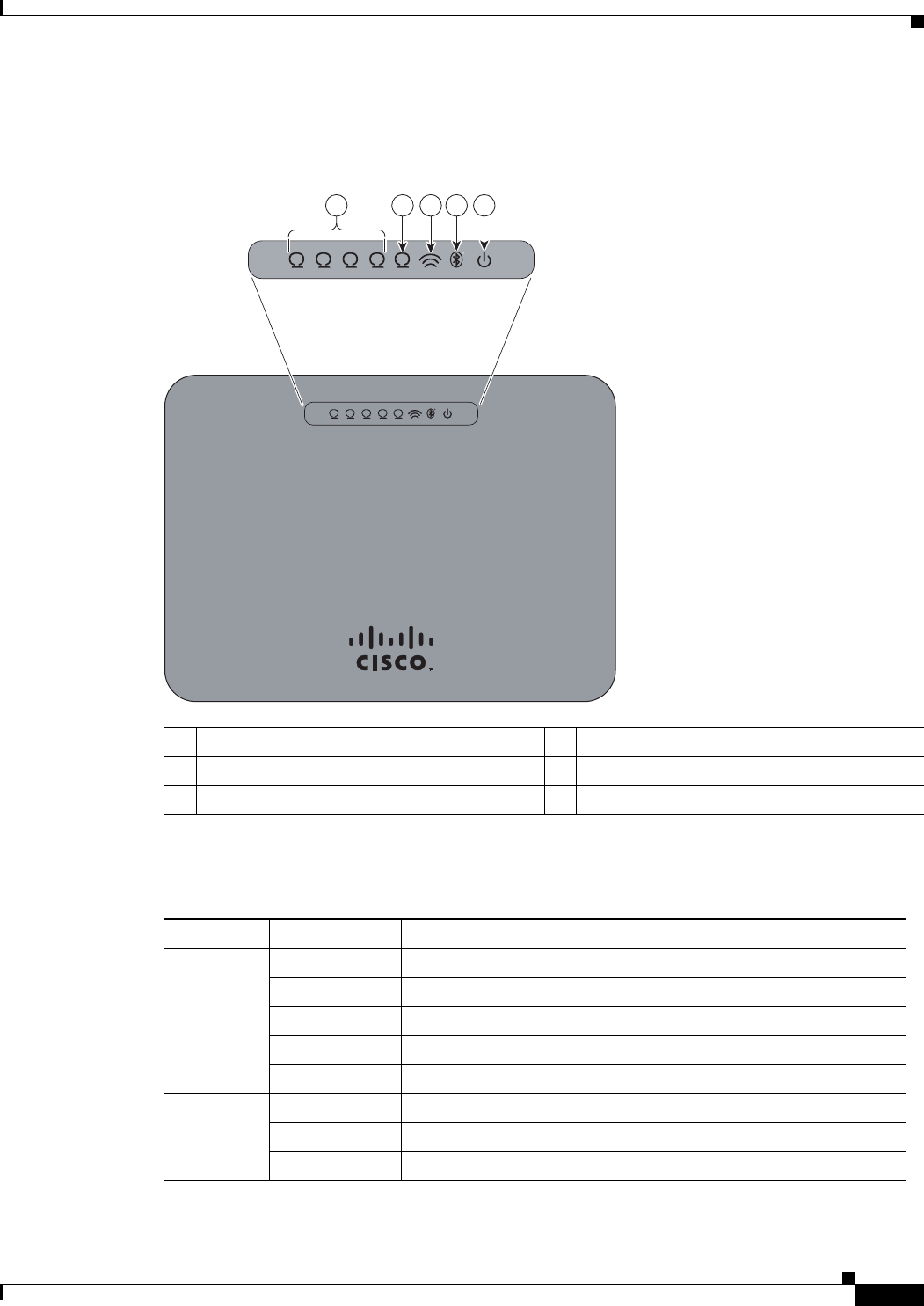
LEDs
Figure 4 Cisco Edge 300 Series Switch LEDs
1Ethernet downlink 4Bluetooth1
2Gigabit Ethernet uplink 5Power
3WiFi1
1. Only CS-E300-AP-K9 and HS-E300-AP-K9.
Ta b l e 2 L E D s
LED Color Meaning
Ethernet
downlink
Off No link.
Green Link present, no activity. Port is operating at 100 Mb/s.
Blinking green Activity. Port is sending or receiving data at 100 Mb/s.
Amber Link present, no activity. Port is operating at 10 Mb/s.
Blinking amber Activity. Port is sending or receiving data at 10 Mb/s.
Gigabit
Ethernet
Off No link.
Green Link up.
Blinking green Activity.
255420
R
1234
R
12 3 4
5
5
2
13 4 5

6
Cisco Edge 300 Series Switch Installation Guide
OL-24909-01
Installing the Switch
Installing the Switch
You can install the switch on a wall by using the wall-mount bracket or install the switch on a desk or
table by using the desktop bracket. You can also install the switch in a ventilated cabinet using the
wall-mount or desktop bracket.
Equipment That You Need
•Phillips screwdriver
•Scratch awl or other sharp pointed object (wall-mount)
•Electric drill with a 6-mm drill bit (wall-mount)
Before You Begin
Before installing the switch, verify that these guidelines are met:
•Front clearance so that the LEDs can be seen.
•AC power cord reaches from the AC power outlet to the rear-panel connector.
•Cabling is away from sources of electrical noise, such as radios, power lines, and fluorescent
lighting. Make sure that the cabling is safely away from other devices that might damage the cables.
•Airflow around the switch is unrestricted.
•Temperature around the unit does not exceed 104°F (40°C).
•Humidity around the switch does not exceed 85 percent.
•Altitude at the installation site is below 10,000 feet.
•For Ethernet ports, cables from the switch to connected devices are not longer than 328 feet
(100 meters).
WiFi Off WiFi is disabled.
Green WiFi is enabled and functioning.
Blinking green WiFi is transmitting data.
Bluetooth Off Bluetooth is disabled.
Green Bluetooth is enabled and functioning.
Power Off There is no power or the self test has failed.
Green System is operating normally.
Blinking green System software is being upgraded.
Blinking amber System software download has failed.
Table 2 LEDs (continued)
LED Color Meaning

7
Cisco Edge 300 Series Switch Installation Guide
OL-24909-01
Installing the Switch
Warning Statements
Statement 1005
Warning
This product relies on the building’s installation for short-circuit (overcurrent) protection. Ensure that
the protective device is rated not greater than:
20A
Statement 1005
Statement 1071
Statement 1019
Warning
The plug-socket combination must be accessible at all times, because it serves as the main
disconnecting device.
Statement 1019
Statement 1030
Warning
Only trained and qualified personnel should be allowed to install, replace, or service this equipment.
Statement 1030
Statement 1040
Warning
Ultimate disposal of this product should be handled according to all national laws and regulations.
Statement 1040
Statement 1044
Warning
For connections outside the building where the equipment is installed, the following ports must be
connected through an approved network termination unit with integral circuit protection:
10/100/1000 Ethernet
Statement 1044
Warning
IMPORTANT SAFETY INSTRUCTIONS
This warning symbol means danger. You are in a situation that could cause bodily injury. Before you
work on any equipment, be aware of the hazards involved with electrical circuitry and be familiar
with standard practices for preventing accidents. Use the statement number provided at the end of
each warning to locate its translation in the translated safety warnings that accompanied this
device.
Statement 1071
SAVE THESE INSTRUCTIONS

8
Cisco Edge 300 Series Switch Installation Guide
OL-24909-01
Installing the Switch
Statement 1047
Warning
To prevent the system from overheating, do not operate it in an area that exceeds the maximum
recommended ambient temperature of:
104°F (40°C)
Statement 1047
Statement 1074
Warning
Installation of the equipment must comply with local and national electrical codes.
Statement 1074
Statement 1076
Warning
To prevent airflow restriction, allow clearance around the ventilation openings to be at least:
3 inches (7.6 cm)
Statement 1076
Caution Be aware of the size and weight of the switch when mounting. Ensure that the mounting location has a
stable flat surface and can safely support the weight of the switch.
Installing the Switch on a Wall
Statement 378
Warning
Read the wall-mounting instructions carefully before beginning installation. Failure to use the
correct hardware or to follow the correct procedures could result in a hazardous situation to people
and damage to the system.
Statement 378
You can mount the switch horizontally or vertically on a wall.
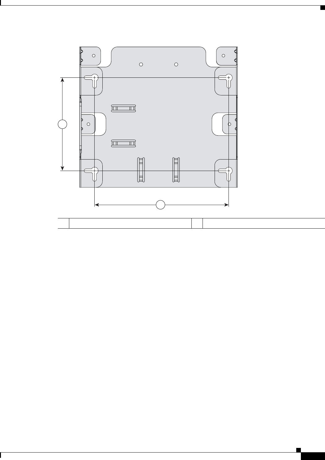
Note The wall-mount bracket has four slots (in two pairs) on its bottom panel (see Figure 5).
9
Cisco Edge 300 Series Switch Installation Guide
OL-24909-01
Installing the Switch
Figure 5 Bracket Slot Distances for Wall-Mounting
14.17 inches (106 mm) 26.02 inches (153 mm)
255421
1
2
10
Cisco Edge 300 Series Switch Installation Guide
OL-24909-01
Installing the Switch
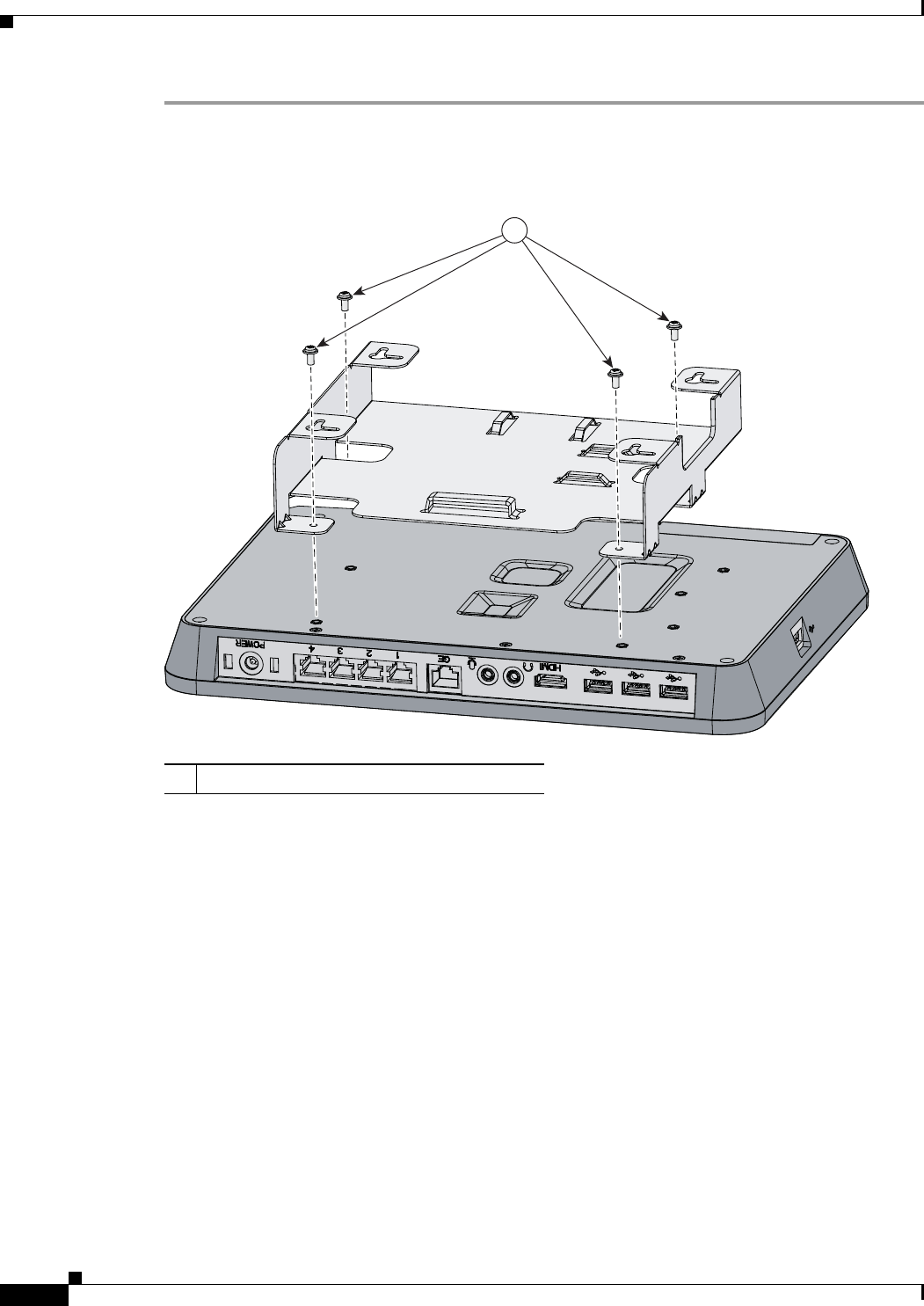
Step 1 Use the four M3.0 x 6-mm Phillips pan head screws to attach the wall-mount bracket to the bottom of
the switch (see Figure 6).
Figure 6 Attaching the Wall-Mount Bracket
Step 2 Connect all the cables that are necessary for your installation.
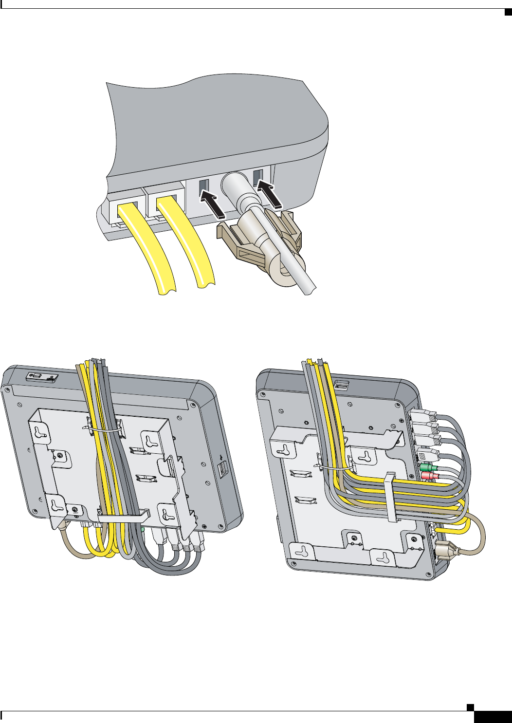
Step 3 Slide the power cord retainer along the power cord, and snap it into the chassis (see Figure 7).
1M3.0 x 6mm Phillips pan head screws
330223
1
11
Cisco Edge 300 Series Switch Installation Guide
OL-24909-01
Installing the Switch
Figure 7 Installing the Power Cord Retainer
Use the supplied cable tie and built-in cable clip to secure the cables to the bracket (see Figure 8).
Figure 8 Routing the Cables — Wall-Mount
Step 4 Determine where you want to mount the switch and its orientation. Make sure that the wall is smooth,
flat, dry, and sturdy. Make sure that the location is within reach of an electrical outlet.
Step 5 Mark the locations on the wall for the mounting screws. Make sure that the holes are the proper distance
apart, depending on the switch orientation.
255426
POWER
255427
12
Cisco Edge 300 Series Switch Installation Guide
OL-24909-01
Installing the Switch
Note If you are mounting the switch on a wooden wall (not drywall), you can screw the tapping screws
directly into the wall.
Step 6 Drill four 0.25-inch (6-mm) holes that are at least 1 inch (25 mm) deep.
Step 7 Insert the plastic drywall anchors into the holes.
Step 8 Insert a tapping screw into each anchor, and leave 0.06 inches (1.5 mm) of the screw head exposed.
Step 9 Place the bracket slots over the tapping screws, and slide the bracket down until the screws fit snugly
into the slots.
Install the Switch on a Desk or Table
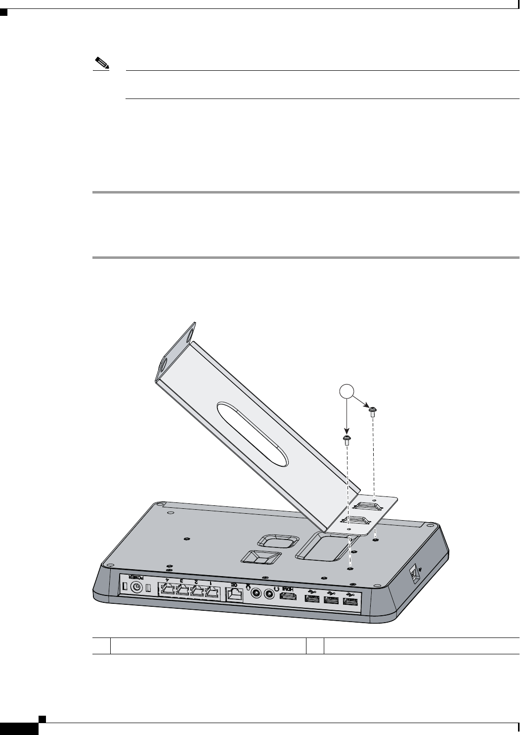
Step 1 Use the two M3.0 x 6-mm Phillips pan head screws to attach the desktop bracket to the bottom of the
switch (see Figure 9).
Figure 9 Attaching the Desktop Bracket
Step 2 Connect all the cables that are necessary for your installation.
1M3.0 x 6mm Phillips pan head screws
255424
1
13
Cisco Edge 300 Series Switch Installation Guide
OL-24909-01
Installing the Switch
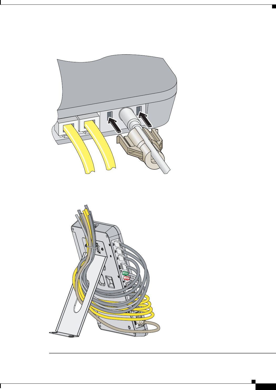
Step 3 Slide the power cord retainer along the power cord, and snap it into the chassis (see Figure 7).
Figure 10 Installing the Power Cord Retainer
Step 4 Use the supplied cable tie to secure the cables to the bracket (see Figure 11).
Figure 11 Routing the Cables — Desktop
Step 5 Place the switch on a desk or table.
255426
POWER
255428
14
Cisco Edge 300 Series Switch Installation Guide
OL-24909-01
Installing the Switch
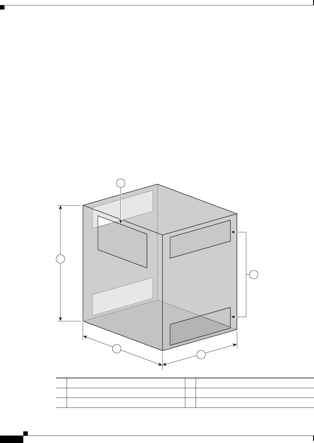
Installing the Switch in a Cabinet
You can install the switch in a ventilated cabinet. To ensure adequate ventilation, make sure that the
cabinet meets the following specifications:
•Minimum dimensions (H x W x D): 19.69 x 19.69 x 15.75 inches (50 x 50 x 40 cm)
•Ventilation openings:
–
The front panel must have one ventilation opening measuring at least 11.81 x 5.91 inches
(30 x 15 cm). The ratio of the ventilation openings should be greater than 30%.
–
Each side panel must have two ventilation openings (one along the top, and one along the
bottom) measuring at least 12.60 x 3.54 inches (32 x 9 cm). The ratio of the ventilation openings
should be greater than 30%.
•Switch placement:
–
For wall-mount placement, install the switch at the rear of the cabinet.
–
For desktop placement, place the switch at the center of the cabinet.
Figure 12 Cabinet Dimensions
111.81 x 5.91 inches (30 x 15 cm) 419.69 inches (50 cm)
212.60 x 3.54 inches (32 x 9 cm) 519.69 inches (50 cm)
315.75 inches (40 cm)
255799
1
2
3
4
5

15
Cisco Edge 300 Series Switch Installation Guide
OL-24909-01
Powering on the Switch
Powering on the Switch
Connect the power cord to an electrical outlet. Press the Power button to power on the switch.
See Table 2 on page 5 for a description of the LED colors and their meanings.
Restoring the Factory Settings
Caution Resetting the switch deletes the existing configuration.
Step 1 Press and hold the Reset button for more than 5 seconds.
Step 2 Press and hold the Power button until the switch shuts down.
Step 3 Press the Power button to restart the switch.
Technical Specifications
Table 3 Cisco Edge 300 Series Switch Environmental and Physical Specifications
Environmental Ranges
Operating temperature 23 to 104°F (–5 to 40°C)
Storage temperature –13 to 158°F (–25 to 70°C)
Relative humidity Operating and nonoperating: 10 to 90% (noncondensing)
Operating altitude Up to 10,000 ft (3000 m)
Storage altitude Up to 15,000 ft (4570 m)
Physical Specifications
Weight (without bracket) 2.43 lb (1.1 kg)
Dimensions (H x W x D) 8.27 x 11.42 x 1.22 in. (21 x 29 x 3.1 cm)
Table 4 Regulatory Standards Compliance for the Cisco Edge 300 Series Switch
Specification Description
Safety IEC 60950-1
GB4943
CCC (China compulsory certification)
EMC China EMC Certifications
Bluetooth BQB
WIFI 802.11b/g/n Mark
Wireless SRRC

16
Cisco Edge 300 Series Switch Installation Guide
OL-24909-01
Obtaining Documentation and Submitting a Service Request
Obtaining Documentation and Submitting a Service Request
For information on obtaining documentation, submitting a service request, and gathering additional
information, see the monthly What’s New in Cisco Product Documentation, which also lists all new and
revised Cisco technical documentation, at:
http://www.cisco.com/en/US/docs/general/whatsnew/whatsnew.html
Subscribe to the What’s New in Cisco Product Documentation as a Really Simple Syndication (RSS) feed
and set content to be delivered directly to your desktop using a reader application. The RSS feeds are a free
service and Cisco currently supports RSS Version 2.0.
For More Information
These documents provide complete information about the switch and are available from this
Cisco.com site:
www.cisco.com/web/CN/products/products_netsol/switches/products/e300/index.html
•Cisco Edge 300 Series Switch Software Configuration Guide
•Release Notes for the Cisco Edge 300 Series Switch
Note Before installing, configuring, or upgrading the switch, refer to the release notes for the
latest information.
Cisco and the Cisco Logo are trademarks of Cisco Systems, Inc. and/or its affiliates in the U.S. and other countries. A listing of Cisco's trademarks
can be found at www.cisco.com/go/trademarks. Third party trademarks mentioned are the property of their respective owners. The use of the word
partner does not imply a partnership relationship between Cisco and any other company. (1005R)
Any Internet Protocol (IP) addresses used in this document are not intended to be actual addresses. Any examples, command display output, and
figures included in the document are shown for illustrative purposes only. Any use of actual IP addresses in illustrative content is unintentional and
coincidental.
© 2011 Cisco Systems, Inc. All rights reserved.
FCC Statement
This equipment has been tested and found to comply with the limits for a Class A
digital device, pursuant to part 15 of the FCC Rules. These limits are designed to
pro-vide reasonable protection against harmful interference when the equipment is
operated in a commercial environment. This equip-ment generates, uses, and can
radiate radio frequency energy and, if not installed and used in accordance with the
instruction manual, may cause harmful interference to radio communications.
Operation of this equipment in a residential area is likely to cause harmful
interference in which case the user will be required to correct the inter-ference at his
own expense.
FCC Radiation Exposure Statement
This equipment complies with FCC RF radiation exposure limits set forth for an
uncontrolled environment. This transmitter must not be co-located or operating in
conjunction with any other antenna or transmitter. This equipment complies with Part
15 of the FCC Rules.Operation is subject to the following two conditions:
(1) This device may not cause harmful interference, and
(2) This device must accept any interference received, including interference that may
cause undesired operation.
Caution!
The manufacturer is not responsible for any radio or TV interference caused by
unauthorized modifications to this equipment. Such modifications could void the user
authority to operate the equipment.