HON HAI PRECISION IND DB6220 VDSL/GbE WiFi Data Router User Manual 110120 PDG A4001N User Manual Cover
HON HAI Precision Ind. Co., Ltd. VDSL/GbE WiFi Data Router 110120 PDG A4001N User Manual Cover
User Manual.pdf

DB 6520
Installation
User Manual
Copyright © 2014ADB Broadband S.p.A. All rights reserved. This document contains ADB proprietary and confidential
information. No part of this document may be copied, reprinted or reproduced in any material form or electronically,
whether wholly or in part, and no information contained herein may be used or disclosed to third parties unless under a
previous written agreement with ADB Broadband S.p.A setting forth relevant terms and conditions.
Trademarks:
All terms used in this document that are known to be trademarks or service marks have been noted as such. ADB cannot
attest to the accuracy of this information. Other product and corporate names used in this document that may be trade-
marks or service marks of other companies are used only for explanation and to the owner’s benefit, without intent to in-
fringe. Use of a term in this document should not be regarded as affecting the validity of any trademark or service mark.
This publication is subject to change without notice. ADB reserves the right to make changes to equipment design and
system components as well as system documentation and literature as progress in engineering, manufacturing methods,
or other circumstances may warrant.
This publication is intended solely for informational and instructional purposes. Refer to the above as to its possible uses. It
constitutes neither a contract with the user hereof nor a warranty or guarantee with regard to any of the ADB products
described herein nor shall it be construed to grant a license or any other rights under any proprietary rights to information
or material included herein. ADB hereby expressly disclaims any warranty or guarantee, whether express or implied, with
regard to items described herein. Any contract, license, or warranty between ADB and the user hereof is created solely by
separate legal documents.

DB 6520
© (2014) ADB Broadband S.p.A. All Rights Reserved. Proprietary Use Pursuant to Cover Page Instructions.
i
CONTENTS
Welcome 1
About this Guide 1
Naming Convention 1
Conventions 1
Introduction 3
Introduction 3
Package Contents 3
Router Advantages 5
Minimum System and Component Requirements 5
Front Panel 6
Rear Panel 7
Router Installation 10
Introduction 10
Positioning the Router 10
Installing Micro Filters 11
Powering up the router 12
Connecting the Router 12
Technical Specifications 23
Glossary 25

© (2014) ADB Broadband S.p.A. All Rights Reserved. Proprietary Use Pursuant to Cover Page Instructions.
Welcome 1
Welcome
Welcome
ABOUT THIS GUIDE
This guide describes how to install and configure the DB 6520 product. This
guide is intended for use by those responsible for installing and setting up net-
work equipment; consequently, it assumes a basic working knowledge of LANs
(Local Area Networks) and Internet Routers. This guide can be used also for
variants derived from this DB 6520, which are named respectively DB 6220
(which do not provide dual-band radio) and DV 6220 (which do not provide
VDSL bonded functionality).
NAMING CONVENTION
Throughout this guide, the DB 652 is referred to as the “ADSL Wi-Fi Router” or
the “Router”. Category 5 Ethernet Cable is referred to as Ethernet Cable
throughout this guide.
CONVENTIONS
Table 1 and Table 2 list conventions that are used throughout this guide.
DB 6520
© (2014) ADB Broadband S.p.A. All Rights Reserved. Proprietary Use Pursuant to Cover Page Instructions.
2 Welcome
TABLE 1. Notice Icons
Icon
Notice Type
Description
Information note
Information that describes important features or instruc-
tions.
Caution
Information that alerts you to potential loss of data or
potential damage to an application, system, or device.
Warning
Information that alerts you to potential personal injury.
TABLE 2. Text Conventions
Convention
Description
The words “enter” and
“type”
When you see the word “enter” in this guide, you must type some-
thing, and then press Return or Enter. Do not press Return or En-
ter when an instruction simply says “type.”
Keyboard key names
If you must press two or more keys simultaneously, the key
names are linked with a plus sign (+). Example:
Press Ctrl+Alt+Del
Words in italics
Italics are used to:
Emphasize a point.
Denote a new term at the place where it is defined in the text.
Identify menu names, menu commands, and software button
names. Examples: “From the Help menu, select Contents.
Click OK.”

DB 6520
(C) (2014) Pirelli Broadband Solutions S.p.A. All Rights Reserved. Proprietary Use Pursuant to Cover Page Instructions.
Welcome 3

© (2014) ADB Broadband S.p.A. All Rights Reserved. Proprietary Use Pursuant to Cover Page Instructions.
Introduction 3
Introduction
Introduction
INTRODUCTION
The DB 6520 is designed to provide a bonded broadband Internet connection
and provide several wired and wireless LAN connection. The Router also pro-
vides protection in the form of an electronic “firewall” preventing anyone outside
of your network from seeing your files or damaging your computers.
The DB 6520 is a VDSL/2/2+ Bonded router, targeted to residential environ-
ments and SOHO customers, that provides routed broadband services from a
single and modular access point.
The DB 6520 is the ideal solution for:
1. Connecting multiple PCs and Video game consoles;
2. Sharing broadband internet connections with all home computers;
3. Sharing printers and peripherals.
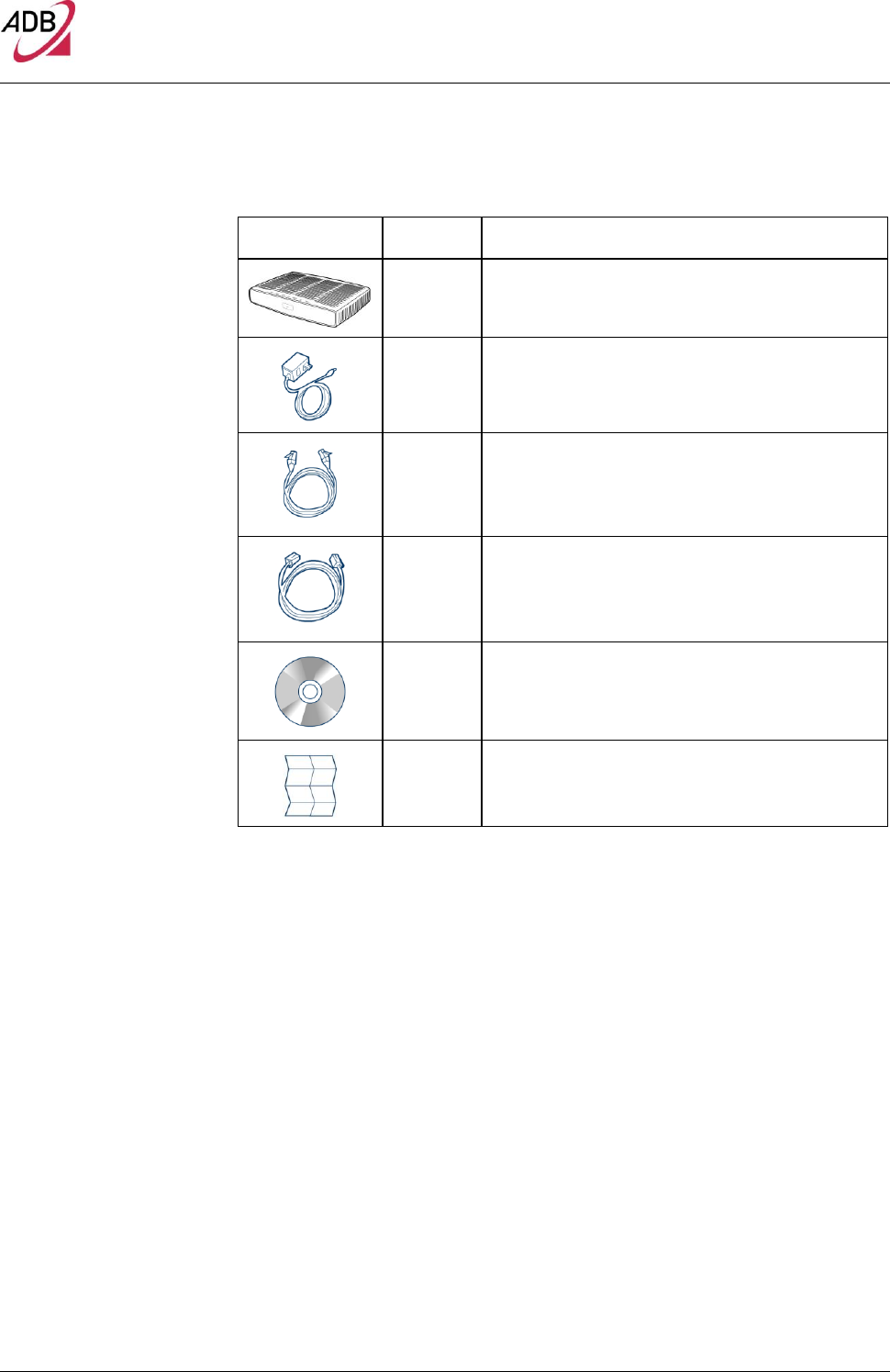
PACKAGE CONTENTS Your new DB 6520 Wireless Router kit contains the related hardware and soft-
ware. You will find into packaging:
1. One DB 6520 unit
2. One Power Supply adapter
3. One Phone cable RJ-11 plug (xDSL) (Gray)
4. One Ethernet CAT5 cable RJ-45 plug (Yellow)
5. A CD-ROM
6. A Safety Leaflet
DB 6520
© (2014) ADB Broadband S.p.A. All Rights Reserved. Proprietary Use Pursuant to Cover Page Instructions.
4 Introduction
TABLE 1. Kit Material
Quantity
DESCRIPTION
1
DB 6520
1
Power Supplier Adapter
1
Ethernet CAT5 cable RJ-45 plug (Yellow)
1
Phone cable RJ-11 plug (DSL) (Gray)
1
CD-ROM
1
Safety leaflet
If any of the items included in the package is damaged, please contact your
Service Provider.
DB 6520 implements an “always-on” Very high asymmetric Digital Subscriber
Line (VDSL) connection to the telephone line on the WAN side, as well as sev-
eral local connectivity technologies on the LAN side:
Five switched 10/100/1000 Base-TX Ethernet ports
One HomePNA over Coax interface
Two USB 2.0 Host port for external USB peripherals
One IEEE 802.11b/g/n Wireless LAN access point 2x2 high power @2,4GHz
One IEEE 802.11b/g/n Wireless LAN access point 3x3 high power @5GHz
Two VDSL WAN interface with RJ-11 port
DB 6520
© (2014) ADB Broadband S.p.A. All Rights Reserved. Proprietary Use Pursuant to Cover Page Instructions.
Introduction 5
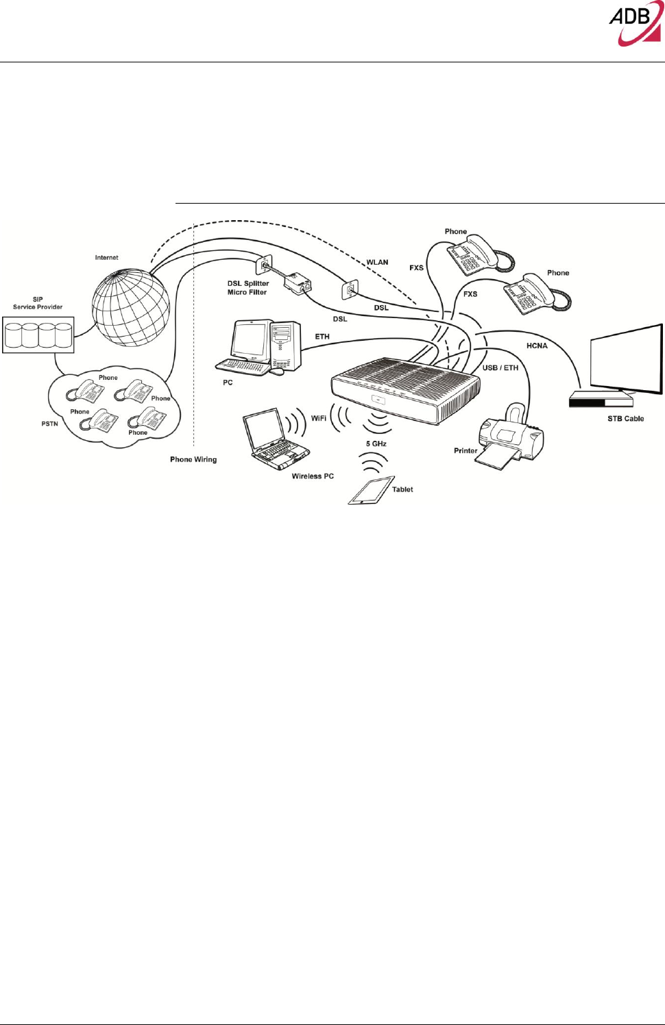
Figure 1 shows a sample network. Your Router becomes your connection to the
Internet.
FIGURE 1. Sample Home Network
ROUTER ADVANTAGES The advantages of the Router include:
Shared Internet connection for both wired and wireless computers
High speed 802.11b/g/n wireless networking with dual radio access
No need for a dedicated, “always on” computer serving as your Internet con-
nection
Cross-platform operation for compatibility with Microsoft® Windows and Ap-
ple® MAC computers (see Technical description for supported platforms).
Easy-to-use, Web-based setup and configuration
Centralization of all network address settings (DHCP)
a Virtual server to enable remote access to Web, FTP and other services on
your network
a Security - Firewall protection - against Internet hacker attacks and encryp-
tion to protect wireless network traffic
A multi-language GUI.
MINIMUM SYSTEM AND
COMPONENT
REQUIREMENTS Your Router requires the computer(s) and components in your network to be
configured with at least the following:
DB 6520
© (2014) ADB Broadband S.p.A. All Rights Reserved. Proprietary Use Pursuant to Cover Page Instructions.
6 Introduction
A computer with the Operating Systems that support TCP/IP networking pro-
tocols: Microsoft® Windows 98SE, Windows ME, Windows 2000, Windows
XP 32bit, Windows Vista, Windows 7, or Apple® MAC 10.x
An Ethernet 10Mbps or 10/100 Mbps NIC for each computer to be connect-
ed to one of the four Ethernet ports on the rear of the Router
As optional, an 802.11b/g wireless NIC
Supported Browsers: Internet Explorer, Netscape, Firefox, Chrome, Safari
and Opera.
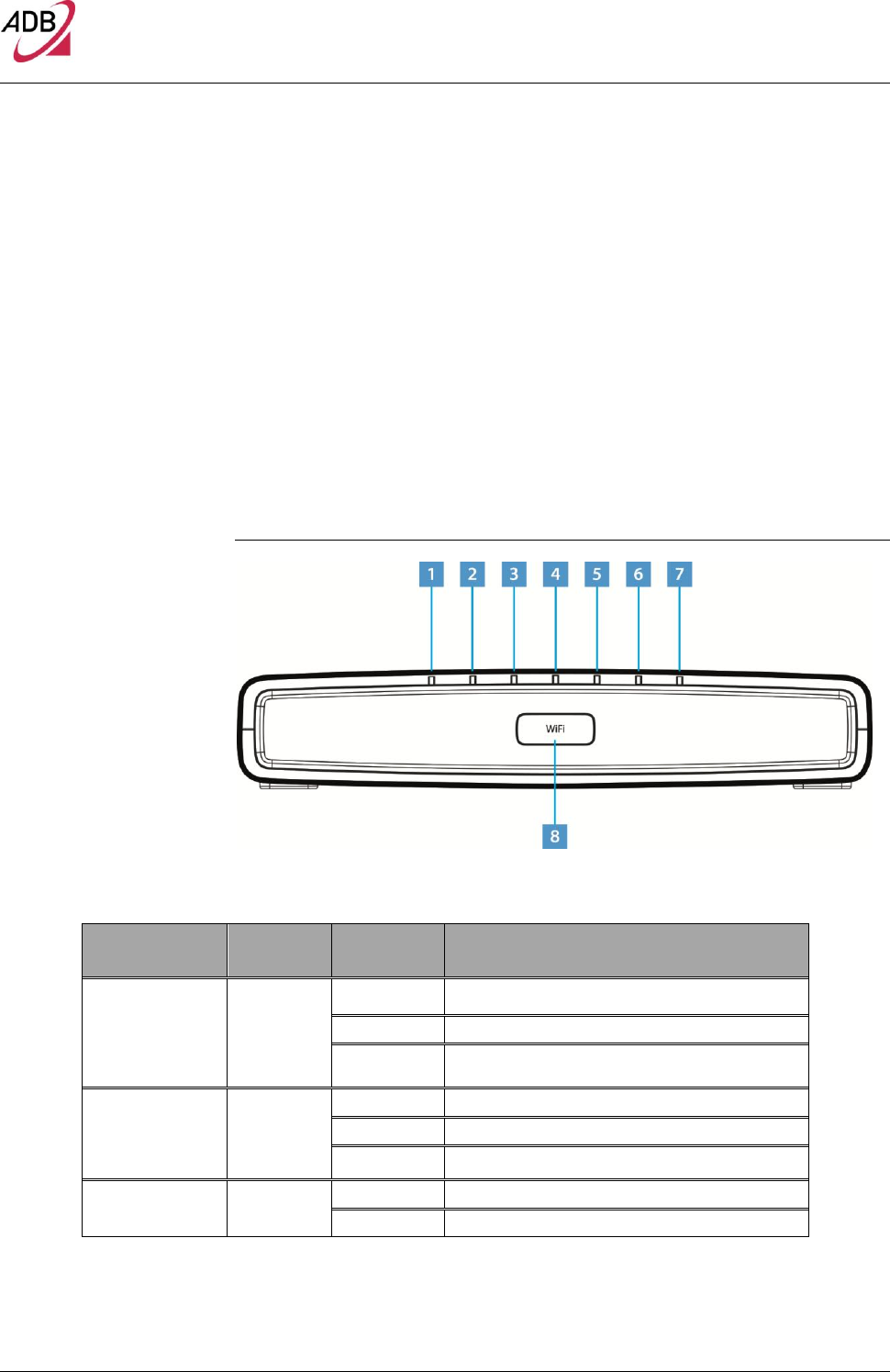
FRONT PANEL The front panel of the Router contains indicator lights (LEDs) that help to de-
scribe the state of networking and connection operations.
FIGURE 2. Front Panel LEDs
TABLE 2. Front Panel LEDs explanation
LED Position
Color
Status
Description
Power
Green/Red
Solid Green
Power on
Light off
Power off
Solid red
Power on self-test /Device Malfunction (not bootable)
and device malfunction
HCNA
Green
Solid Light
Device connected to LAN port
Blinking
LAN Activity present
Light off
No Activity
USB
Green
Solid Green
USB Link established
Blinking Green
USB activity present (traffic in either direction)
DB 6520
© (2014) ADB Broadband S.p.A. All Rights Reserved. Proprietary Use Pursuant to Cover Page Instructions.
Introduction 7
Light off
No USB Link established
Wi-Fi / WPS
(button/LED)
Green /
Red
Solid Green
Wi-Fi
Wireless is activated on modem. OR
WPS
Successful PC synchronization: after the
blinking phase it turns solid and keep this state for 10
sec.
Solid Red
WPS
WPS failed
Blinking
Wi-Fi
Wireless activity is present
WPS
Attempting PC synchronization
Light off
Wi-Fi
Wireless off or no device attached
WPS
WPS not started
WAN Eth
Green
Solid Light
IP connected and no traffic detected
Blinking
IP connected and Internet traffic detected
Light off
Modem power off, modem in bridged mode or DSL
connection not present
DSL
Green
Solid Light
DSL good sync.
Blinking
DSL attempting sync.
Light off
No carrier signal
Internet
Green/Red
Solid Green
IP connected and no traffic detected
Solid Red
Authentication failed
Blinking Green
IP connected and Internet traffic detected
ETH1-4
Green
Solid Light
Device connected to LAN port
Blinking
LAN Activity present
Light off
No Activity
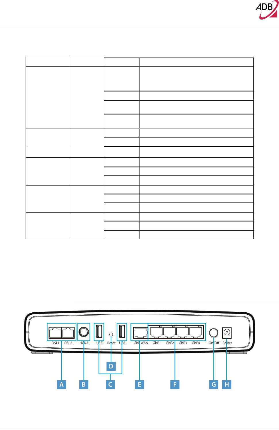
REAR PANEL The rear panel of the Router contains a reset button, a power adapter socket,
five LAN ports, one HCNA port, two VDSL port, and two USB Host ports.
FIGURE 3. Rear Panel Ports

DB 6520
© (2014) ADB Broadband S.p.A. All Rights Reserved. Proprietary Use Pursuant to Cover Page Instructions.
8 Introduction
TABLE 3. Port Description
PORT
DESCRIPTION
A
2x Phone DSL connector (VDSL)
B
HCNA port
C
Two USB Host ports
D
Reset to factory
E
One Ethernet WAN port 10/100/1000 Mbps
F
Four Ethernet LAN ports 10/100/1000 Mbps
G
Power On/Off button
H
Power socket

© (2014) ADB Broadband S.p.A. All Rights Reserved. Proprietary Use Pursuant to Cover Page Instructions.
Router Installation 10
Router Installation
Router
Installation
INTRODUCTION This chapter will guide you through a basic installation of the Router including:
1. Positioning the DB 6520
2. Installing Micro Filters
3. Connecting the Router to your network
4. Setting up your computer for networking with the Router
Please read carefully the Safety Information in Appendix “A”
POSITIONING THE ROUTER You should place the Router in such a location to ensure that:
It is located near an electrical outlet and a phone wall socket
Water or moisture cannot enter the case of the unit
It is out of direct sunlight and away from sources of heat
The cabling is away from power lines, fluorescent lighting fixtures, and
sources of electrical noise such as radios, transmitters and broadband am-
plifiers.
It is centrally located with respect to the wireless devices that will be con-
nected to the Router. A suitable location might be on top of a high shelf to
ensure the maximum coverage for all connected devices.
DB 6520
© (2014) ADB Broadband S.p.A. All Rights Reserved. Proprietary Use Pursuant to Cover Page Instructions.
Router Installation 11
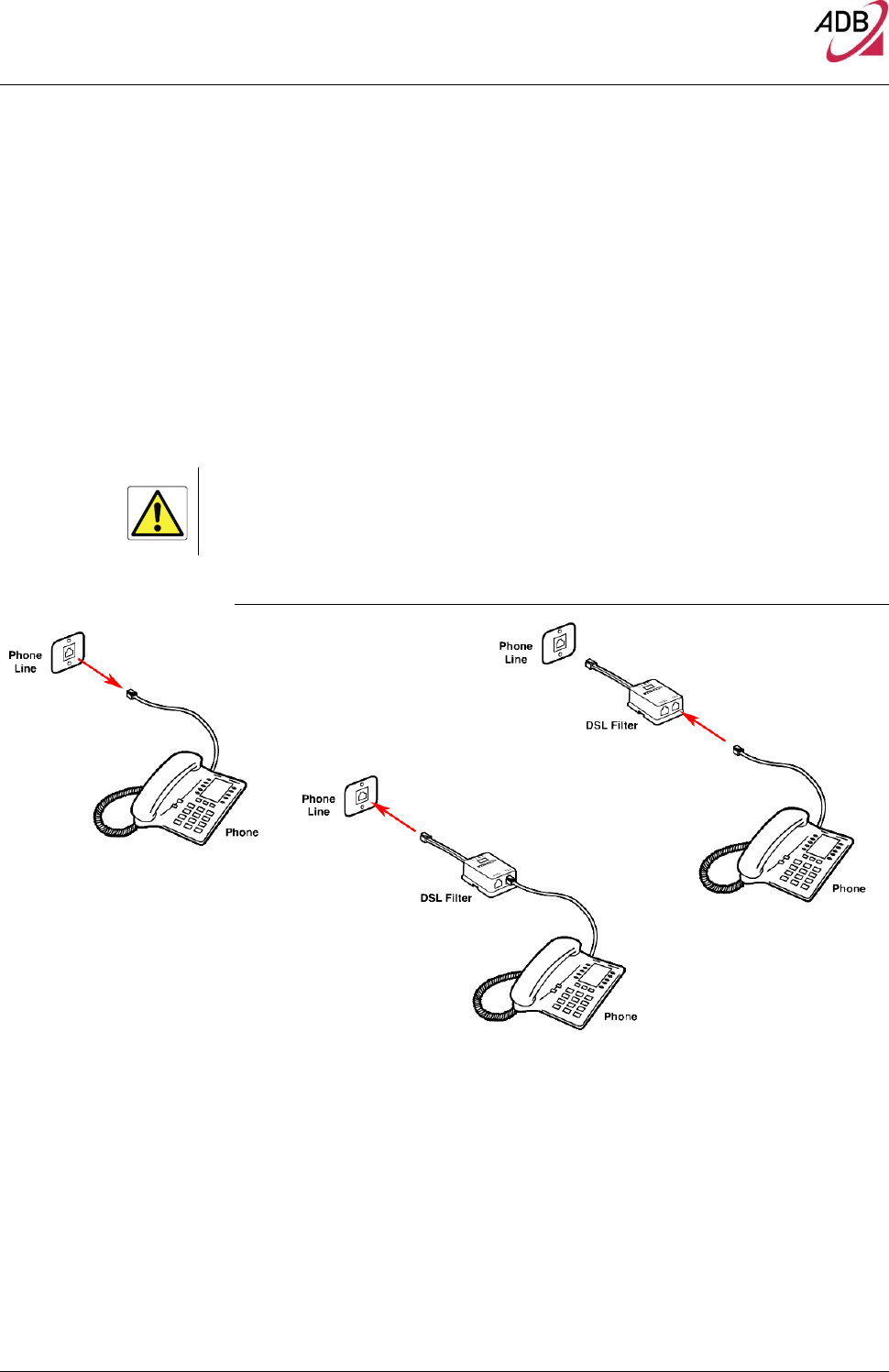
INSTALLING MICRO
FILTERS Before beginning installation you must locate devices in your house requiring a
DSL filter such as phones, fax machines, answering machines, dial-up mo-
dems, Satellite TV dialers or monitored security systems and attach a DSL filter
to any one of them sharing the same phone line as your DSL modem.
To install DSL filters please follow these steps:
1. Disconnect the phone cable from the telephone wall socket
2. Insert the phone cable into the DSL filter port identified with a phone symbol
3. Insert the DSL filter cable into the telephone wall socket
You do not need to attach a DSL filter to unused wall sockets.
FIGURE 1. Micro Filter Installation
1
3
2
DB 6520
© (2014) ADB Broadband S.p.A. All Rights Reserved. Proprietary Use Pursuant to Cover Page Instructions.
12 Router Installation
POWERING UP THE
ROUTER To power up the Router:
1. Plug the power adapter into the power adapter port located on the rear of
the Router
2. Plug the power adapter into a standard electrical wall socket
3. Press the Power button located on the rear panel of the Router
4. Wait for the power LED to turn steady green
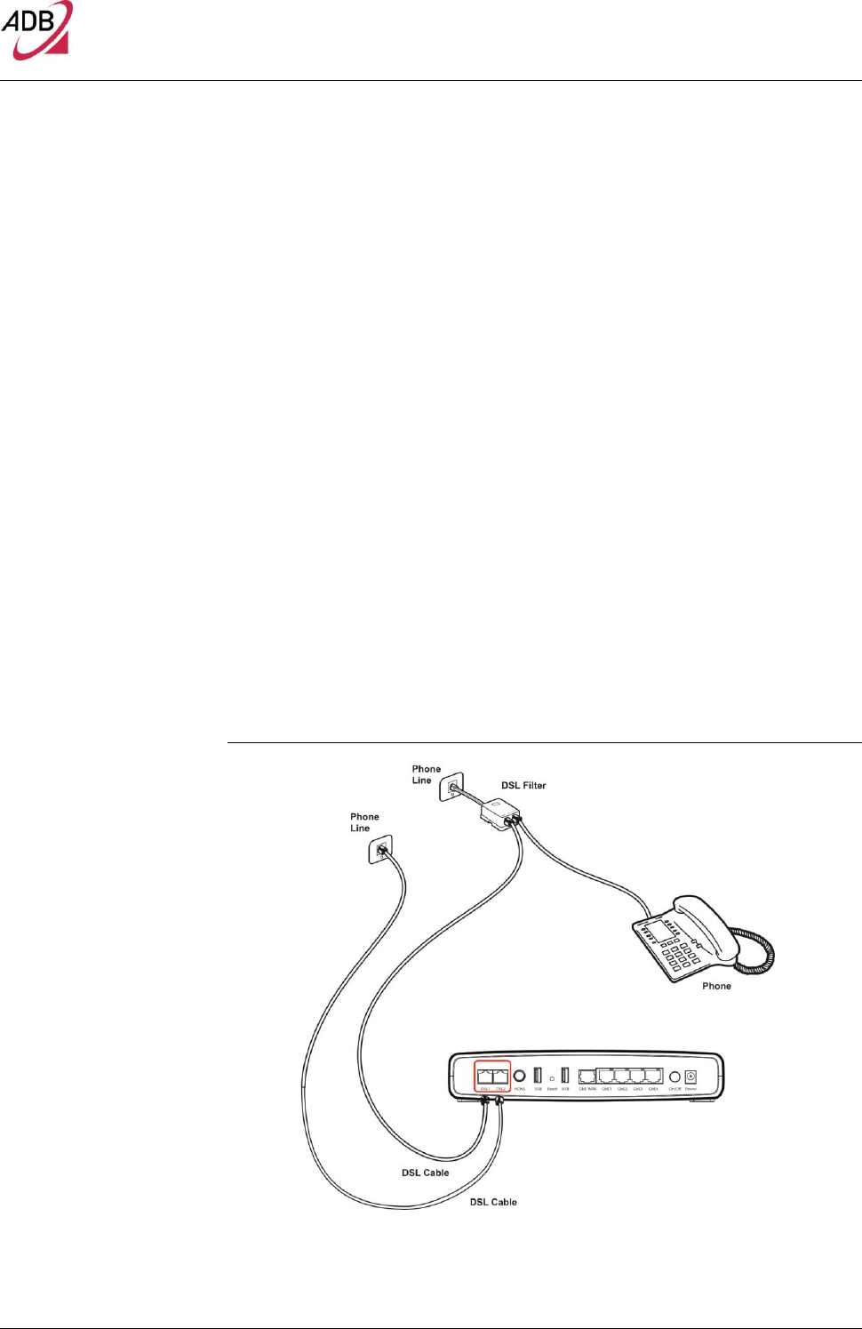
CONNECTING THE
ROUTER The first step to install the router is to physically connect it to the telephone
socket and then connect it to a computer by means of an Ethernet connection.
To connect the phone cables (valid only for bonding models):
1. Connect one end of the first phone cable into the DSL filter port; the other
end of the phone cable shall be inserted into the first DSL port on the rear of
the Router.
2. Connect one end of the second phone cable into second phone line con-
nector available on the wall; the other end of the cable shall be connected to
the second DSL port on the rear panel of the router. (this is valid only for
bonded models)
FIGURE 2. Phone Cables Connection
DB 6520
© (2014) ADB Broadband S.p.A. All Rights Reserved. Proprietary Use Pursuant to Cover Page Instructions.
Router Installation 13
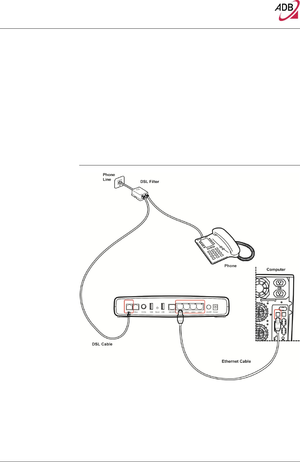
To connect the Ethernet cable:
1. Connect one end of the Ethernet cable into one of the four Ethernet ports on
the rear of the Router
2. Connect the other end of the Ethernet cable into the Ethernet Network card
of your computer
3. Verify if the Ethernet Network card is configured as DHCP client, otherwise
configure it to remain in the same local network of the router interface (see
chapter “Setting Up Your Computer”)
FIGURE 3. Ethernet Cable Connection
ETHERNET CONNECTION You have to verify the existence of a TCP/IP protocol stack and, then, according
to your Operating System, to establish an Ethernet connection to the Data
Gateway. This connection will require you to enable your computer to receive

DB 6520
© (2014) ADB Broadband S.p.A. All Rights Reserved. Proprietary Use Pursuant to Cover Page Instructions.
14 Router Installation
from the Data Gateway its own IP Address automatically: in such a case, the
Data Gateway acts like the DHCP server in your local network.
TCP/IP CONFIGURATION To access the Internet through the Data Gateway, you must configure the net-
work settings of the computers on your LAN to use the same IP subnet as Data
Gateway. The default IP settings for the Data Gateway are:
IP ADDRESS: 192.168.1.1
SUBNET MASK: 255.255.255.0
These settings can be changed to fit your network requirements, but you must
first configure at least one computer to access the Data Gateway's web configu-
ration interface in order to make the required changes.
ETHERNET CONNECTION
>> TCP/IP PROTOCOL
INSTALLATION This procedure requires the TCP/IP protocol installed on your computer. Refer
to the following paragraphs and to your Windows and MacOS operating sys-
tems manuals.
Microsoft Windows Vista / Windows 7
TCP/IP stack is considered a core component of the operating system, so it
cannot be installed or uninstalled. You must check in this case that Internet Pro-
tocol (TCP/IP) is enabled. To do so, follow these steps:
1. Starting from Start -> Control Panel -> Network & Internet -> Network Con-
nections depending on the configuration of your computer.
2. Select the Network Adapter icon and from the contextual menu, do select the
Properties item.
3. In the General TAB panel, verify that Internet Protocol v4 (TCP/IPv4) item is
checked; if not, do check it and click on the OK button.
Microsoft Windows XP
TCP/IP stack is considered a core component of the operating system, so it
cannot be installed or uninstalled. You must check in this case that Internet Pro-
tocol (TCP/IP) is enabled. To do so, follow these steps:
1. Starting from Start -> Settings -> Control Panel or Start -> Control Panel de-
pending on the configuration of your computer.
2. Make a double click on the Network Connections icon.
3. Select the Network Adapter icon and from the contextual menu, do select the
Properties item.
4. In the General TAB panel, verify that Internet Protocol (TCP/IP) item is
checked; if not, do check it and click on the OK button.

DB 6520
© (2014) ADB Broadband S.p.A. All Rights Reserved. Proprietary Use Pursuant to Cover Page Instructions.
Router Installation 15
Microsoft Windows 98SE, ME, 2000
1. Insert your Windows installation CD-ROM into the CD-ROM drive.
2. Starting from Start -> Settings -> Control Panel or Start -> Control Panel de-
pending on the configuration of your computer.
3. Make a double click on the Network and Dial-up Connections icon.
4. Select the interested Network Adapter icon and from the contextual menu, do
select the Properties item.
5. If the Internet Protocol (TCP/IP) component is not checked you must enable
it by checking the Internet Protocol (TCP/IP) item; otherwise, if it is not listed,
you must install it by selecting the Install... button.
6. Choose the Protocol Network component and click on the add button.
7. In the Select Network Protocol panel, do choose Internet Protocol (TCP/IP)
and the OK button.
8. After rebooting, you're ready to configure the TCP/IP setting, as described in
the following paragraphs.
Apple MacOS 10.x
TCP/IP is installed on a MacOS system as part of Open Transport.
ETHERNET CONNECTION
>> MS WINDOWS VISTA /
WINDOWS 7 To configure TCP/IP on MS Windows Vista / Windows 7 Operating Systems fol-
low these steps:
1. Select Start -> Control Panel -> Network & Internet and make a double click
on the Network Connections icon.
2. Select the adapter card interested by TCP/IP configuration.
3. Select the Properties item from the contextual Adapter Card menu.
4. Select in the General TAB panel, the Internet Protocol (TCP/IPv4) item and
then click on Properties button.
5. In the General TAB panel, check the Obtain an IP address automatically radio
button and the Obtain DNS server address automatically radio button. Click
on OK button.
ETHERNET CONNECTION
>> MS WINDOWS XP
To configure TCP/IP on MS Windows XP Operating System follow these steps:
1. Select Start -> Settings -> Control Panel and make a double click on the Net-
work Connections icon.
2. Select the adapter card interested by TCP/IP configuration.
3. Select the Properties item from the contextual Adapter Card menu.
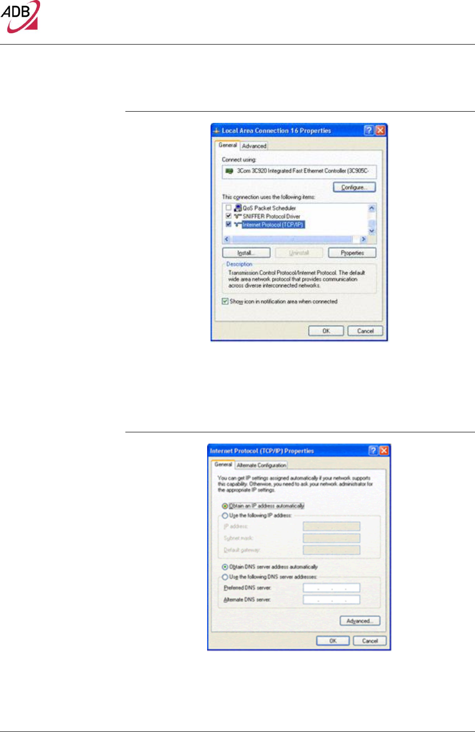
4. Select in the General TAB panel, the Internet Protocol (TCP/IP) item and then
click on Properties button.
DB 6520
© (2014) ADB Broadband S.p.A. All Rights Reserved. Proprietary Use Pursuant to Cover Page Instructions.
16 Router Installation
FIGURE 4. Local Area Connection Properties
5. In the General TAB panel, check the Obtain an IP address automatically radio
button and the Obtain DNS server address automatically radio button. Click
on OK button.
FIGURE 5. Internet Protocol (TCP/IP) Properties
DB 6520
© (2014) ADB Broadband S.p.A. All Rights Reserved. Proprietary Use Pursuant to Cover Page Instructions.
Router Installation 17
ETHERNET CONNECTION
>> MS WINDOWS 98SE, ME,
2000 To configure TCP/IP on these Operating Systems follow these steps:
1. Select Start -> Settings -> Control Panel and make a double click on the Net-
work and Dial-up Connection icon.
2. Select the adapter card interested by TCP/IP configuration and then select
the Properties item from its contextual menu.
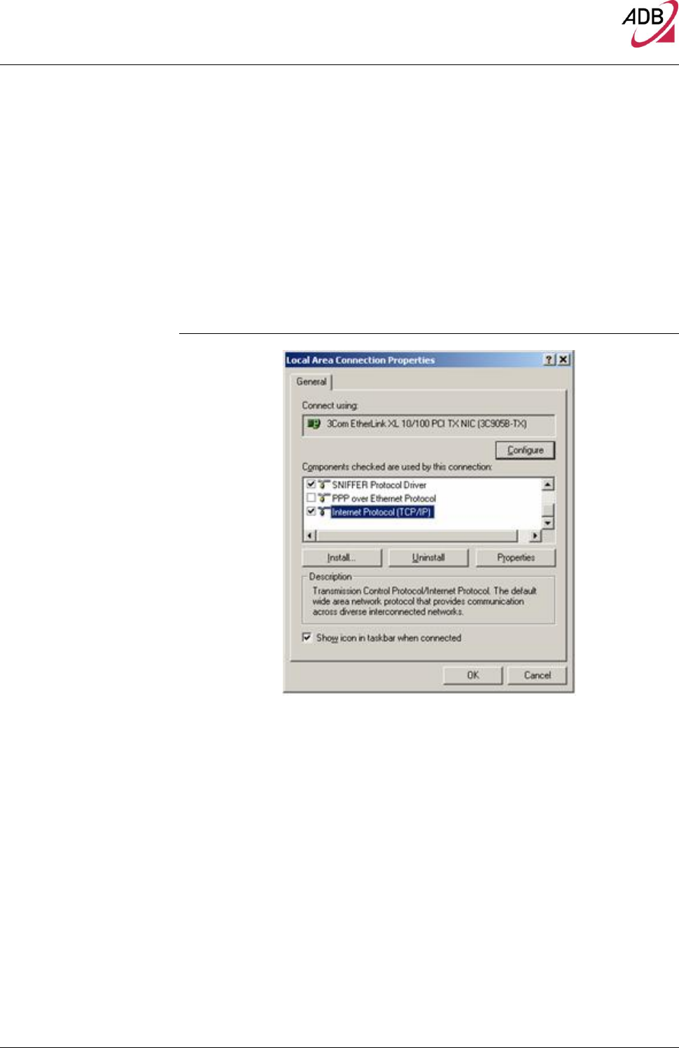
3. Select Internet Protocol (TCP/IP) item then click on Properties button.
FIGURE 6. Local Area Connection Properties
1. Select the General TAB panel, then check the Obtain an IP address auto-
matically and Obtain DNS server address automatically radio buttons. Click
on OK button.
DB 6520
© (2014) ADB Broadband S.p.A. All Rights Reserved. Proprietary Use Pursuant to Cover Page Instructions.
18 Router Installation
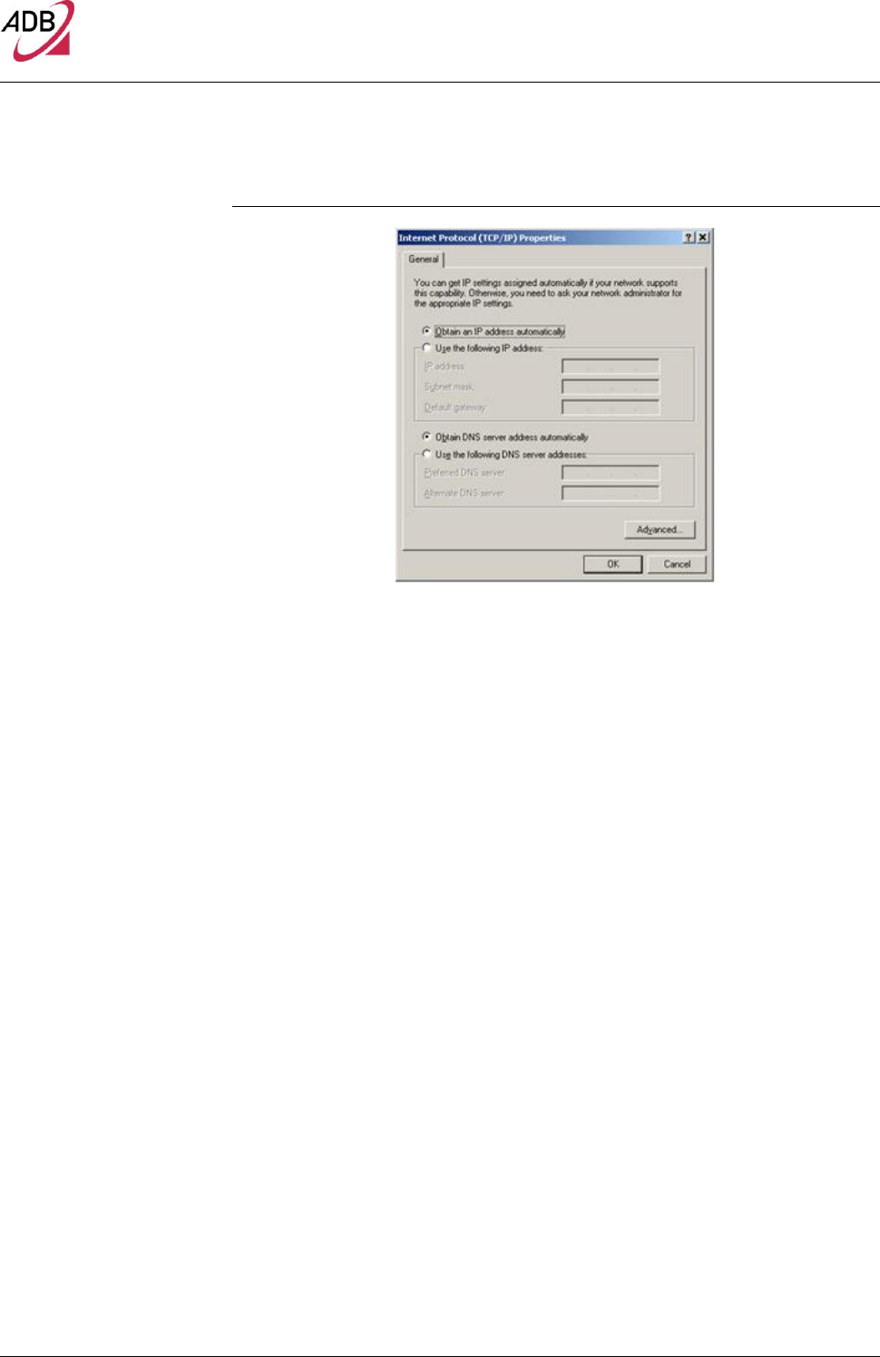
FIGURE 7. Internet Protocol (TCP/IP) Properties
5. A system reboot will be required to make the changes real.
DISABLE HTTP PROXY
You need to verify that the “HTTP proxy” feature of your web browser is disa-
bled. This is required in order that your browser can view the Gateway’s HTML
configuration pages.
OBTAIN IP SETTINGS FROM YOUR DATA
GATEWAY >> MS WINDOWS XP / VISTA / 7
Now that you’ve configured your computer to connect to your Data Gateway, it
needs to obtain new network settings. By releasing old DHCP IP settings and
renewing them with settings from your Data Gateway, you can verify that you’ve
configured your computer correctly.
2. On the Windows desktop, click Start > Programs > Accessories > Com-
mand Prompt menu item
3. In the Command prompt window, type “ipconfig/release” and press the
ENTER key
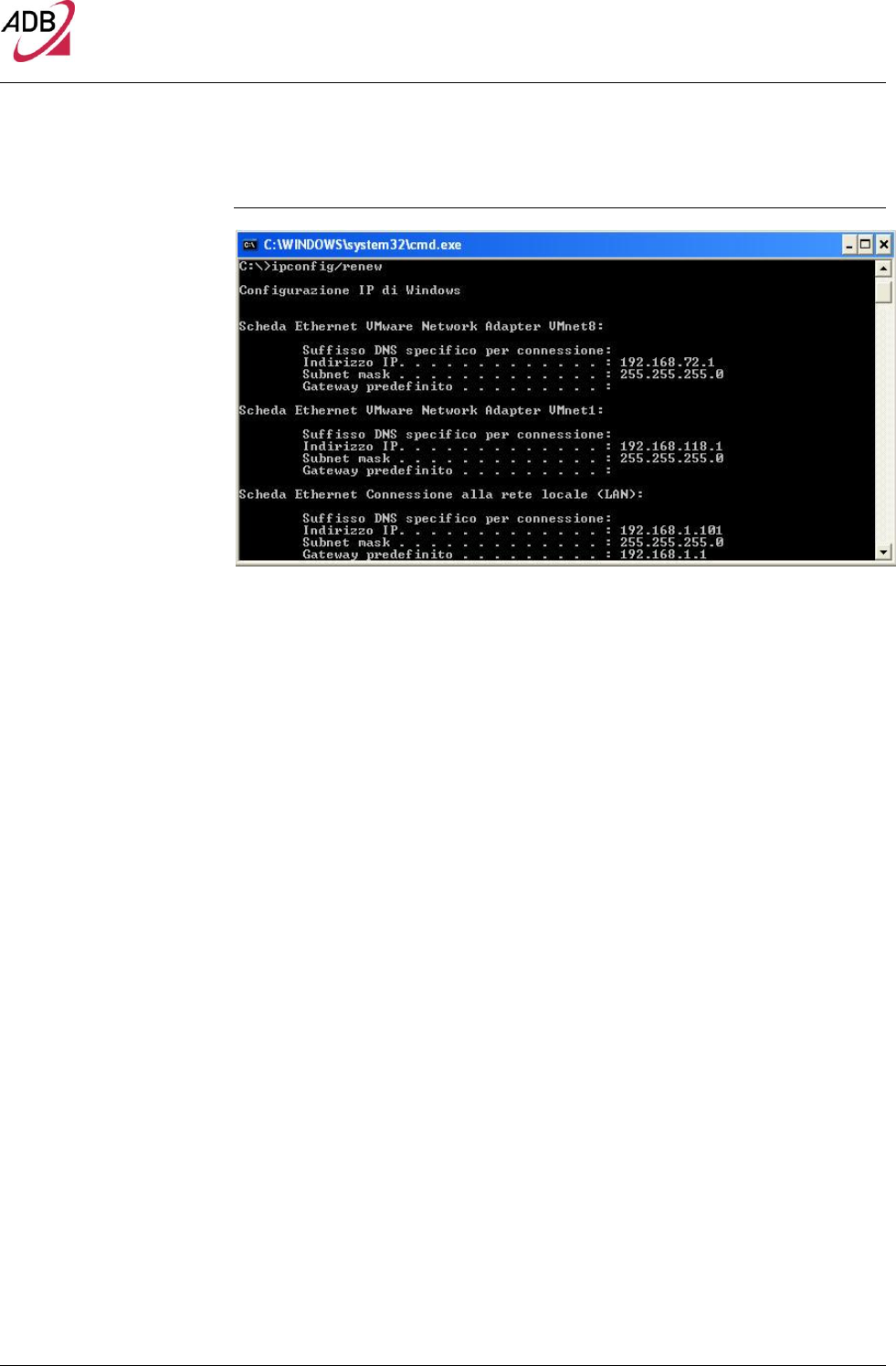
4. Type “ipconfig/renew” and press the ENTER key. Verify that your IP Ad-
dress is now 192.168.1.xxx, your Subnet Mask is 255.255.255.0 and your
Default Gateway is 192.168.1.1. These values confirm that your xDSL Data
Gateway is functioning
5. Close the Command Prompt window
DB 6520
© (2014) ADB Broadband S.p.A. All Rights Reserved. Proprietary Use Pursuant to Cover Page Instructions.
Router Installation 19
OBTAIN IP SETTINGS
FROM YOUR DATA
GATEWAY
>> MS WINDOWS 98SE, ME,
2000
Now that you’ve configured your computer to connect to your Data Gateway, it
needs to obtain new network settings. By releasing old DHCP IP settings and
renewing them with settings from your Data Gateway, you can verify that you’ve
configured your computer correctly.
6. On the Windows desktop, select the Start > Programs > Accessories >
Command Prompt menu item
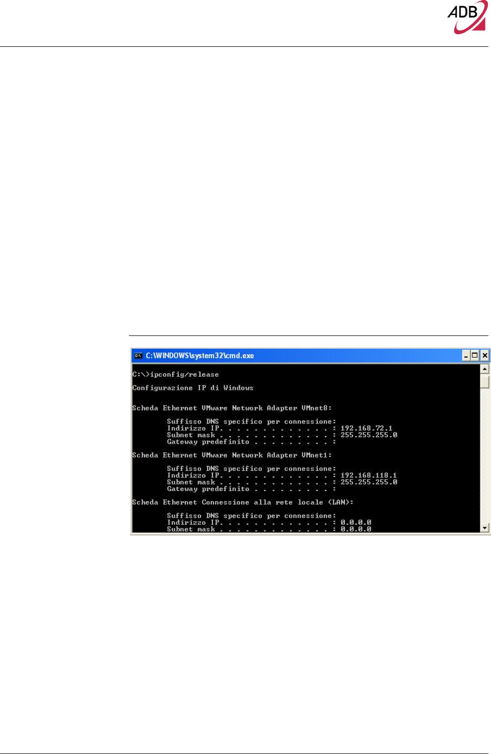
7. In the Command prompt window, type “ipconfig/release” and press the
ENTER key
FIGURE 8. Command Prompt (IPCONFIG command)
8. Type “ipconfig/renew” and press the ENTER key. Verify that your IP Ad-
dress is now 192.168.1.xxx, your Subnet Mask is 255.255.255.0 and your
Default Gateway is 192.168.1.1. These values confirm that your xDSL Data
Gateway is functioning.
DB 6520
© (2014) ADB Broadband S.p.A. All Rights Reserved. Proprietary Use Pursuant to Cover Page Instructions.
20 Router Installation
FIGURE 9. Command Prompt (IPCONFIG command)
9. Close the Command Prompt window
ETHERNET CONNECTION
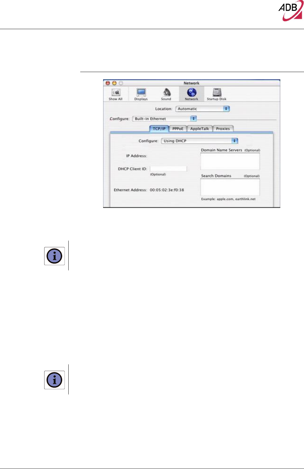
>> MAC OS 10.X To configure TCP/IP on MAC OS 10.x follow these steps:
10. Open the Apple Menu > System Preferences and select Network.
11. From the Show drop down list, according to the type of connection used,
select Built-in Ethernet.
12. Select the TCP/IP tab.
13. Select DHCP from the Configure pop-up menu to have a dynamic IP ad-
dress. Click Apply Now.
14. Click on the Register button to save the changes in the Control Panel.
15. Enter http://192.168.1.1/ in the address bar of your browser to open the DB
6520 Home Page.
DB 6520
© (2014) ADB Broadband S.p.A. All Rights Reserved. Proprietary Use Pursuant to Cover Page Instructions.
Router Installation 21
FIGURE 10. Network panel on MAC OS 10.x
WI-FI CONNECTION
It requires a computer with 802.11b/g/n (Wi-Fi Certified) wireless adapter installed.
1. Install your wireless adapter according to the manufacturer’s instructions
and verify that your computer is set to obtain an IP address automatically
(DHCP mode).
2. Upon wireless adapter installation and driver setup, please check in the
Network Connections panel – accessible through your OS Control Panel –
that the Wireless Network Connection is enabled. If not, enable it by right
clicking on the Wireless Network Connection item and by selecting “Enable”.
3. In case of an hardware wireless switch, please check that it is set to ON.
Usually a steady lighted or flashing led will notify you the wireless connection
up. Please consult your PC or notebook manual to get information on proper
hardware switching and related led behavior.
You will need to properly configure your adapter to communicate with the DB 6520 according to the
configuration rules.
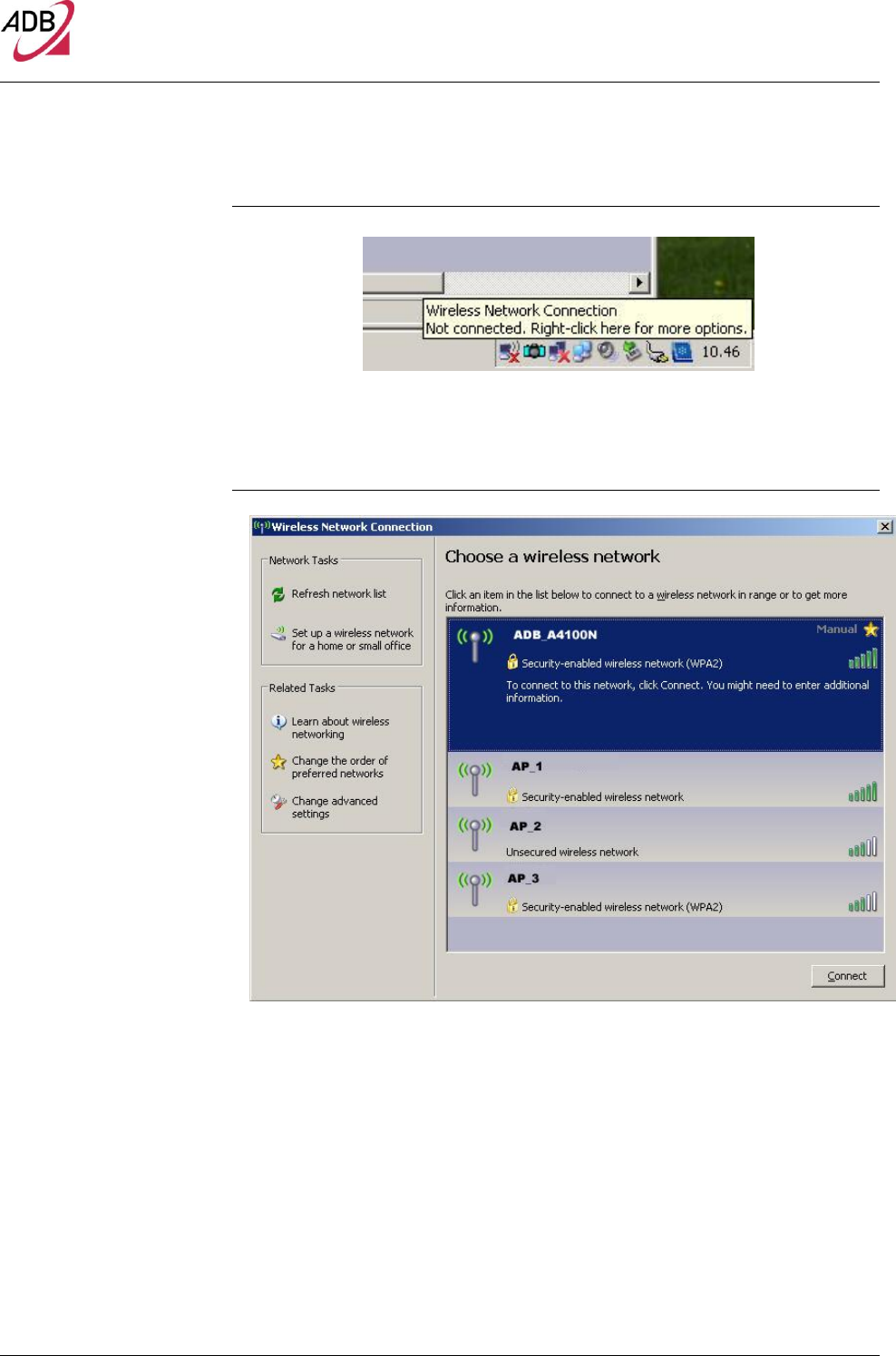
4. An icon will be shown in the quick tray icon bar at the bottom of your screen
to notify you the current wireless connection state (see Figure 12)
DB 6520
© (2014) ADB Broadband S.p.A. All Rights Reserved. Proprietary Use Pursuant to Cover Page Instructions.
22 Router Installation
FIGURE 11. Wireless connection icon (Windows XP)
5. By double clicking on the wireless icon, a panel will appear showing you all
available wireless network
FIGURE 12. Wireless network connection panel (Windows XP)
6. Double click on the SSID of the DB 6520 in the Access Points list
7. A panel will appear asking you to insert the wireless key as defined in Chap-
ter 7 (“Wireless Section”).

23
A
Technical Specifications
This section lists the technical specifications for the DB 6520.
Interfaces/Standard
WAN Interface
(*) Nr.2 Line port (RJ-11 plug) supporting the following standards:
- ADSL (G.992.1, G992.2, T1.413, G994.1, G.997.1)
- ADSL2 (G.992.3)
- ADSL2+ (G992.5)
- VDSL2 (G993.2)
- (*) For model DV 6220 there is N.1 Line port
Nr.1 Gigabit WAN Ethernet 10/100/1000 BASE-T/TX (RJ-45 plug), compliant IEEE 802.3, with
auto MDIX and auto-negotiation
LAN Interface
- Nr. 4 10/100/1000 BASE-T/TX Ethernet ports (RJ-45 plug), compliant IEEE 802.3, with
auto MDIX and auto-negotiation
- Nr. 1 HomePNA over Coax v.3.1
- Nr. 2 USB Host v. 2.0
Wireless Interface
Wi-Fi access point solution is compliant with:
- IEEE 802.11b/g/n @2.4 GHz High Power
- (*) IEEE 802.11 b/g/n@5GHz High power
- WPA/WPA2 (IEEE 802.11i)
- WMM (IEEE 802.11e)
- Internal antennas
- (*) For models DB 6220 and DV 6220 the Wi-Fi is Single radio only.
DSL (ATM)
Features
- AAL5 (ITU-T I.363.5)
- UBR, VBR-nrt, VBR-rt, CBR traffic classes
- ATM support for ADSL
- Multiple VC/PPP connections
- Multi-protocol encapsulation over AAL5, RFCs 2684
- Up to 8 PVC
- Pre-emptive SAR
- Possibility of multiple physical queues (up to 8) per traffic class, with priority-based
scheduling support
- OAM (ITU-T I.610)
- F4, F5
- Loop-back
- Encapsulation modes in ATM stack: LLC SNAP and VC-Mux

24
WAN Protocol
Encapsulation
- Bridged/Routed Ethernet over ATM (RFC 2684 / RFC 1483)
- PPP over Ethernet (RFC 2516)
- PPP over ATM (RFC 2364)
- IP over ATM (RFC 1577)
Routing / Bridging
- IPv4/IPv6
- NAT/NAPT, RFCs 3022, Static NAT/NAPT
- DHCP Server/Client/Relay
- DNS relay
- VPN pass-through
- Application Level Gateway (ALGs) modules
- Spanning tree protocol
- IP Multicasting – IGMP v1, v2, v3
- Transparent Bridging (IEEE802.1d)
QoS
- IP QoS
- Traffic shaping (ATM layer)
- Priority-based scheduling (up to 8* queues, max 4 per PVC )
- Diffserv (RFC2474, RFC2475) marking and queuing according to connection type,
network interface, MAC, IP
- Port based QoS
File sharing and
Printer Server
- File Sharing
- Printer Server with SMB protocol
Security
- Programmable firewall, Stateful Packet Inspection (SPI) Firewall
- IP protocol filtering
Management
- Broadband Forum TR-069 CPE Management Protocol:
- Auto- configuration and dynamic service provisioning
- Software/firmware image management
- Status and performance monitoring
- Diagnostics and LOGs
- Telnet with CLI
- WEB server with Admin/User configuration Pages
Environmental
Specifications
Temperature (ETS 300-019-1-3):
- Operating: +5° to 40° C
- Non Operating: -20° to 70°C
Relative Humidity (ETS 300-019-1-3):
- Operating: 10% to 90% non-condensing
- Non Operating: 5% to 95% non-condensing
Power Adapter
- INPUT: 100/240Vac 50/60 Hz
- OUTPUT: 12Vdc 3A (For models DB 6220 and DV 6220 it is 12Vdc 2.5A)

25
B
Glossary
802.11b
The IEEE specification for wireless Ethernet which allows speeds of up to 11 Mbps. The standard provides
for 1, 2, 5.5 and 11 Mbps data rates. The rates will switch automatically depending on range and environ-
ment.
802.11g
The IEEE specification for wireless Ethernet which allows speeds of up to 54 Mbps. The standard provides
for 6, 9, 12, 18, 24, 36, 48 and 54 Mbps data rates. The rates will switch automatically depending on range
and environment.
802.11n
The IEEE specification for wireless Ethernet which allows speeds of up to 300 Mbps. The standard provides
for 7,2 up to 300 Mbps data rates. The rates will switch automatically depending on range and environment.
10BASE-T
The IEEE specification for 10 Mbps Ethernet over Category 3, 4 or 5 twisted pair cable.
100BASE-TX
The IEEE specification for 100 Mbps Fast Ethernet over Category 5 twisted-pair cable.
1000BASE-TX
The IEEE specification for 1 Gbps Gigabit Ethernet over Category 5 twisted-pair cable.
Access Point
An Access Point is a device through which wireless clients connect to other wireless clients and which acts
as a bridge between wireless clients and a wired network, such as Ethernet. Wireless clients can be moved
anywhere within the coverage area of the access point and still connect with each other. If connected to an
Ethernet network, the access point monitors Ethernet traffic and forwards appropriate Ethernet messages to
the wireless network, while also monitoring wireless client radio traffic and forwarding wireless client mes-
sages to the Ethernet LAN.

26
Ad Hoc mode
Ad Hoc mode is a configuration supported by most wireless clients. It is used to connect a peer to peer net-
work together without the use of an access point. It offers lower performance than infrastructure mode, which
is the mode the router uses. (see also Infrastructure mode.
Auto-negotiation
Some devices in the range support auto-negotiation. Auto-negotiation is where two devices sharing a link,
automatically configure to use the best common speed. The order of preference (best first) is: 100BASE-TX
full duplex, 100BASE-TX half duplex, 10BASE-T full duplex, and 10BASE-T half duplex. Auto-negotiation is
defined in the IEEE 802.3 standard for Ethernet and is an operation that takes place in a few milliseconds.
Bandwidth
The information capacity, measured in bits per second, that a channel can transmit. The bandwidth of Ether-
net is 10 Mbps, the bandwidth of Fast Ethernet is 100 Mbps. The bandwidth for 802.11b wireless is 11Mbps.
Category 5 Cables
One of five grades of Twisted Pair (TP) cabling defined by the EIA/TIA-586 standard. Category 5 can be
used in Ethernet (10BASE-T) and Fast Ethernet networks (100BASE-TX) and can transmit data up to
speeds of 100 Mbps. Category 5 cabling is better to use for network cabling than Category 3, because it
supports both Ethernet (10 Mbps) and Fast Ethernet (100 Mbps) speeds.
Channel
Similar to any radio device, the Wireless Cable/DSL router allows you to choose different radio channels in
the wireless spectrum. A channel is a particular frequency within the 2.4GHz spectrum within which the
Router operates.
Client
The term used to described the desktop PC that is connected to your network.
DHCP
Dynamic Host Configuration Protocol. This protocol automatically assigns an IP address for every computer
on your network. Windows 95, Windows 98 and Windows NT 4.0 contain software that assigns IP addresses
to workstations on a network. These assignments are made by the DHCP server software that runs on Win-
dows NT Server, and Windows 95 and Windows 98 will call the server to obtain the address. Windows 98
will allocate itself an address if no DHCP server can be found.
DMZ
DMZ (Demilitarized Zone) is an area outside the firewall, to let remote users to have access to items on your
network (Web site, FTP download and upload area, etc.).

27
DNS Server Address
DNS stands for Domain Name System, which allows Internet host computers to have a domain name (such
as pirelli.com) and one or more IP addresses (such as 192.168.10.8). A DNS server keeps a database of
host computers and their respective domain names and IP addresses, so that when a domain name is re-
quested (as in typing “pirelli.com” into your Internet browser), the user is sent to the proper IP address. The
DNS server address used by the computers on your home network is the location of the DNS server your
ISP has assigned.
DSL
Short for digital subscriber line, but is commonly used in reference to the asymmetric version of this technol-
ogy (ADSL) that allows data to be sent over existing copper telephone lines at data rates of from 1.5 to 9
Mbps when receiving data (known as the downstream rate) and from 16 to 640 Kbps when sending data
(known as the upstream rate). ADSL requires a special ADSL modem. ADSL is growing in popularity as
more areas around the world gain access.
DSL modem
DSL stands for digital subscriber line. A DSL modem uses your existing phone lines to send and receive da-
ta at high speeds.
Encryption
A method for providing a level of security to wireless data transmissions. The Router uses two levels of en-
cryption; 40/64 bit and 128 bit. 128 bit is a more powerful level of encryption than 40/64 bit.
Ethernet
A LAN specification developed jointly by Xerox, Intel and Digital Equipment Corporation. Ethernet networks
use CSMA/CD to transmit packets at a rate of 10 Mbps over a variety of cables.
Ethernet Address
See MAC address.
Fast Ethernet
An Ethernet system that is designed to operate at 100 Mbps.
Firewall
Electronic protection that prevents anyone outside of your network from seeing your files or damaging your
computers.
Full Duplex
A system that allows packets to be transmitted and received at the same time and, in effect, doubles the po-
tential throughput of a link.

28
IEEE
Institute of Electrical and Electronics Engineers. This American organization was founded in 1963 and sets
standards for computers and communications.
IETF
Internet Engineering Task Force. An organization responsible for providing engineering solutions for TCP/IP
networks. In the network management area, this group is responsible for the development of the SNMP pro-
tocol.
IGMP
The Internet Group Management Protocol (IGMP) is an Internet protocol that provides a way for an Internet
computer to report its multicast group membership to adjacent routers. Multicasting allows one computer on
the Internet to send content to multiple other computers that have identified themselves as interested in re-
ceiving the originating computer's content. Multicasting can be used for such applications as updating the
address books of mobile computer users in the field, sending out company newsletters to a distribution list,
and
"broadcasting" high-bandwidth programs of streaming media to an audience that has "tuned in" by setting up
a multicast group membership.
Infrastructure mode
Infrastructure mode is the wireless configuration supported by the Router. You will need to ensure all of your
clients are set up to use infrastructure mode in order for them to communicate with the Access Point built into
your Router. (see also Ad Hoc mode)
IP
Internet Protocol. IP is a layer 3 network protocol that is the standard for sending data through a network. IP
is part of the TCP/IP set of protocols that describe the routing of packets to addressed devices. An IP ad-
dress consists of 32 bits divided into two or three fields: a network number and a host number or a network
number, a subnet number, and a host number.
IP Address
Internet Protocol Address. A unique identifier for a device attached to a network using TCP/IP. The address
is written as four octets separated with periods (full-stops), and is made up of a network section, an optional
subnet section and a host section.
ISP
Internet Service Provider. An ISP is a business that provides connectivity to the Internet for individuals and
other businesses or organizations.
LAN
Local Area Network. A network of end stations (such as PCs, printers, servers) and network devices (hubs
and switches) that cover a relatively small geographic area (usually not larger than a floor or building). LANs
are characterized by high transmission speeds over short distances (up to 1000 metres).

29
MAC
Media Access Control. A protocol specified by the IEEE for determining which devices have access to a
network at any one time.
MAC Address
Media Access Control Address. Also called the hardware or physical address. A layer 2 address associated
with a particular network device. Most devices that connect to a LAN have a MAC address assigned to them
as they are used to identify other devices in a network. MAC addresses are 6 bytes long.
Mbps
Megabits per second.
MDI/MDIX
In cable wiring, the concept of transmit and receive are from the perspective of the PC, which is wired as a
Media Dependant Interface (MDI). In MDI wiring, a PC transmits on pins 1 and 2. At the hub, switch, router,
or access point, the perspective is reversed, and the hub receives on pins 1 and 2. This wiring is referred to
as Media Dependant Interface - Crossover (MDI-X).
NAT
Network Address Translation. NAT enables all the computers on your network to share one IP address. The
NAT capability of the Router allows you to access the Internet from any computer on your home network
without having to purchase more IP addresses from your ISP.
Network
A Network is a collection of computers and other computer equipment that are connected for the purpose of
exchanging information or sharing resources. Networks vary in size, some are within a single room, others
span continents.
Network Interface Card (NIC)
A circuit board installed into a piece of computing equipment, for example, a computer, that enables you to
connect it to the network. A NIC is also known as an adapter or adapter card.
Protocol
A set of rules for communication between devices on a network. The rules dictate format, timing, sequencing
and error control.
PSTN
Public Switched Telephone Network.

30
PPPoA
Point-to-Point Protocol over ATM. PPP over ATM is a protocol for connecting remote hosts to the Internet
over an always-on connection by simulating a dial-up connection.
PPPoE
Point-to-Point Protocol over Ethernet. Point-to-Point Protocol is a method of data transmission originally cre-
ated for dial-up connections; PPPoE is for Ethernet connections.
RJ-45
A standard connector used to connect Ethernet networks. The “RJ” stands for “registered jack”.
Router
A device that acts as a central hub by connecting to each computer's network interface card and managing
the data traffic between the local network and the Internet.
Server
A computer in a network that is shared by multiple end stations. Servers provide end stations with access to
shared network services such as computer files and printer queues.
SSID
Service Set Identifier. Some vendors of wireless products use SSID interchangeably with ESSID.
Subnet Address
An extension of the IP addressing scheme that allows a site to use a single IP network address for multiple
physical networks.
Subnet mask
A subnet mask, which may be a part of the TCP/IP information provided by your ISP, is a set of four numbers
configured like an IP address. It is used to create IP address numbers used only within a particular network
(as opposed to valid IP address numbers recognized by the Internet, which must assigned by InterNIC).
Subnets
A network that is a component of a larger network.
Switch
A device that interconnects several LANs to form a single logical LAN that comprises of several LAN seg-
ments. Switches are similar to bridges, in that they connect LANs of a different type; however they connect
more LANs than a bridge and are generally more sophisticated.

31
TCP/IP
Transmission Control Protocol/Internet Protocol. This is the name for two of the most well-known protocols
developed for the interconnection of networks. Originally a UNIX standard, TCP/IP is now supported on al-
most all platforms, and is the protocol of the Internet.
TCP
It relates to the content of the data travelling through a network — ensuring that the information sent arrives
in one piece when it reaches its destination. IP relates to the address of the end station to which data is be-
ing sent, as well as the address of the destination network.
Traffic
The movement of data packets on a network.
Universal plug and play
Universal plug and play is a system which allows compatible applications to read some of their settings from
the Router. This allows them to automatically configure some, or all, of their settings and need less user con-
figuration.
URL Filter
A URL Filter is a feature of a firewall that allows it to stop its clients form browsing inappropriate Web sites.
USB
Universal Serial Bus is a specification to establish communication between devices and a host controller
(usually personal computers).
UTP
Unshielded twisted pair is the cable used by 10BASE-T and 100BASE-Tx Ethernet networks.
VCI
VCI - Virtual Channel Identifier. The identifier in the ATM (Asynchronous Transfer Mode) cell header that
identifies to which virtual channel the cell belongs.
VPI
VPI - Virtual Path Identifier. The field in the ATM (Asynchronous Transfer Mode) cell header that identifies to
which VP (Virtual Path) the cell belongs.
WAN
Wide Area Network. A network that connects computers located in geographically separate areas (for exam-
ple, different buildings, cities, or countries). The Internet is an example of a wide area network.

32
WEP
Wired Equivalent Privacy. A shared key encryption mechanism for wireless networking. Encryption strength
is 40/64 bit or 128 bit.
Wi-Fi
Wireless Fidelity. This is the certification granted by WECA to products that meet their inter operability crite-
ria. (see also 802.11b, WECA)
Wi-Fi Alliance
The Wi-Fi Alliance is a trade group, owning the trademark to Wi-Fi, aiming at performing the testing, certify-
ing interoperability of products and promoting the technology.
Wireless Client
The term used to describe a desktop or mobile PC that is wirelessly connected to your wireless network
Wireless LAN Service Area
Another term for ESSID (Extended Service Set Identifier)
Wizard
A Windows application that automates a procedure such as installation or configuration.
WLAN
Wireless Local Area Network. A WLAN is a group of computers and devices connected together by wireless
in a relatively small area (such as a house or office).
WPA
Wi-Fi Protected Access. A dynamically changing encryption mechanism for wireless networking. Encryption
strength is 256 bit.

ADB Broadband S.p.A
Viale Sarca 222
20126 Milano
http://broadband.adbglobal.com
DOC 256710 rev 0.1 4 1
If trouble is experienced with this VDSL/GbE WiFi Data Router for repair or warranty
information, please contact:
Company Name: COSTAR
Address: 518 VALLEY WAY MILPITAS CA 95035 USA
Tel. No: 408-946-9339
If the equipment is causing harm to the telephone network, the telephone company may
request that you disconnect the equipment until the problem is resolved.
Connection to party line service is subject to state tariffs. Contact the state public utility
commission, public service commission or corporation commission for information.
If your home has specially wired alarm equipment connected to the telephone line, ensure
the installation of this equipment does not disable your alarm equipment. If you have
questions about what will disable alarm equipment, consult your telephone company or a
qualified installer.
WHEN PROGRAMMING EMERGENCY NUMBERS AND(OR) MAKING TEST CALLS TO
EMERGENCY NUMBERS:
1) Remain on the line and briefly explain to the dispatcher the reason for the call.
2) Perform such activities in the off-peak hours, such as early morning or late evenings.
End of life disposal
The crossed-out wheeled bin symbol on the Product or on its packaging indicates
that this Product must not be disposed of with your other household waste.
Instead, it is your responsibility to dispose of your waste equipment by handing it
over to a designated collection point for the recycling of waste electrical and
electronic equipment, or to return it to the dealer when purchasing a new
appliance.
The separate collection and recycling of your waste equipment at the time of
disposal will help to conserve natural resources and ensure that it is recycled in a
manner that protects human health and the environment and supports the reuse
and/or recycling of materials the equipment is made of.
For more information about where you can drop off your waste equipment for
recycling, please contact your local city office or your household waste disposal
service.
The unlawful disposal of the product by the user may entail a fine.
Waste packaging should be separated and delivered at the collection points in
accordance with the local waste collection rules.
FINAL REMARKS
This Product must be installed and used in strict accordance with the manufacturer’s
instructions as described in the enclosed user documentation.
In some cases the use of wireless devices could be limited by the proprietary or
representative of the building. In case of doubts about the disposals and rules regarding the
use of wireless devices in specific environment (ex. airports and hospitals), it is
recommended to ask the authorization before using the Product.
ADB Broadband S.p.A. is not responsible for any radio or television interference caused by
unauthorized modification of this device, or the substitution or attachment of connecting
cables and equipment other than specified by ADB Broadband S.p.A. The correction of
interference caused by such unauthorized modification, substitution or attachment will be the
responsibility of the user. ADB Broadband S.p.A. and its authorized resellers or distributors
are not liable for any damage or violation of government regulations that may arise from the
user failing to comply with these guidelines.
Manufactured by ADB Broadband S.p.A.
P.IVA: 04566350965
Viale Sarca, 222 – 20126 Milano
For further information http://adbglobal.com
REGULATORY COMPLIANCE AND SAFETY INFORMATION
Before any operation is performed, please read the operation instructions and
precautions carefully in order to minimize the possibility of accidents.
When you use this Product you shall always respect basic safety measures in order to
reduce risk of fire, electric shock or injury, following below instructions.
Environmental conditions for Product installation and use
The Product shall be installed and configured in accordance with the user guide.
The Product shall be used and installed indoor with a maximum ambient
temperature of 45 °C and a minimu temperature of -5 °C.
The Product shall be installed in a place with a grade 2 of environmental pollution
(a place without conducting polluting agents).
The Product shall not be placed near any source of heat or direct sunlight.
The Product shall be placed in a well-ventilated area in order to prevent
overheating. Do not cover or block the air vents on the Product. These are
necessary for proper ventilation.
Do not use this Product near water or in close proximity to bath tub, wash bowl,
kitchen sink, or laundry basin, in a wet basement, or near a swimming pool.
The Product Shall not get in contact with water and moisture. Moving the Product
from a cold environment to a hot one may cause moisture on some internal parts
of the device. Wait until the Product is totally dry before turning it on. In case of
fire, do not use water for fire-extinguishing.
The Product shall not be used during a lightning storm. There is a remote risk of
electric shock from lightning.
Interface classification
The external interfaces of the Product are classified as:
xDSL: TNV-3 circuit subject to overvoltages.
xDSL port is classified as TNV-3 circuit. This means that although the cables to be
used for the normal connection in accordance with the installation procedures are
subject to overvoltages, the safety standard are respected.
The other telecommunication ports (Ethernet, HCNA and USB Host) and the low
voltage power supply port: SELV circuit.
External xDSL cables must be connected only to xDSL port. Where these cables
were connected to other ports of the Product does not comply with safety
standards, there may be overvoltages problems.
Ethernet ports must be connected only to devices that support the same kind of
interface, and the cable used must not leave the building where the Product is
installed.
Wireless LAN
The Product is provided with a Wi-Fi interface based on DSSS (Direct Sequence
Spread Spectrum) and OFDM (Orthogonal Frequency Division Modulation) radio
technologies. The Product complies with the IEEE 802.11b/g/n standard and is
Wi-Fi Certified
TM
according to Wi-Fi Alliance.
USB
The equipment has to be connected to a standard USB device compliant with
limited current circuit (as per UL 60950-1/CSA C22.2 No. 60950-1).
2 3
xDSL line cord
To reduce the risk of fire, use only NO. 26 AWG or larger(e.g.. 24 AWG) UL
Listed or CSA certified Telecommunication Line cord.
Follow the guidelines to plug the cords to the device in the same order as
indicated in the user guide.
Do not plug in any case the telecommunication line cord to other ports of the
device (for example Ethernet ports).
Power source
Use only the Class II power adapter provided with the Product. The Product
should be operated only with power source of the same kind as indicated on the
power adapter rating plate.
It is a limited power source as per UL 60950-1/ CSA C22.2 No. 60950-1 and it is
compliant to national standards of the specific country where the Product is
installed. It is strictly forbidden to use different type of power source.
The plug-socket serves as the main disconnecting device. Be sure that the used
power outlet is easily accessible and located as close to the user as possible.
In order to reduce the risk of fire or electric shock, do not overload the electrical
outlet, power strip, or extension power cable.
Cleaning instructions
Unplug the Product from the power outlet (or socket) and any other
telecommunication interfaces before cleaning.
Use a damp cloth for cleaning. Do not use liquid or aerosol cleansers.
Maintenance
Do not open the case in order to avoid electric shock or exposition to
overvoltages.
Improper mounting can cause electric shock during further use of the Product.
There are no parts inside the Product that can be substituted by the user.
Damage requiring service/replacement
In case the Product requires service unplug the Product from the electrical outlet
and contact your service provider.
Typical conditions which may require service:
– Liquid has been spilled into the Product.
– The Product does not operate normally when you follow the operating
instructions.
– The Product has been dropped or damaged.
– There are noticeable signs of overheating.
– The power cord, extension cord, or plug is damaged.
– A burning smell or smoke is perceived from the device.
FCC Statement
This device complies with Part 15 of the FCC Rules. Operation is subject to the following two
conditions:
(1) This device may not cause harmful interference
(2) This device must accept any interference received, including interference that may cause
undesired operation.
This Product has been tested and found to comply with the limits for a Class B digital device,
pursuant to Part 15 of the FCC Rules. These limits are designed to provide reasonable
protection against harmful interference in a residential installation. This equipment generates,
uses and can radiate radio frequency energy and, if not installed and used in accordance
with the instructions, may cause harmful interference to radio communications. However,
there is no guarantee that interference will not occur in a particular installation. If this
equipment does cause harmful interference to radio or television reception, which can be
determined by turning the equipment off and on, the user is encouraged to try to correct the
interference by one or more of the following measures:
– Reorient or relocate the receiving antenna
– Increase the separation between the equipment or devices
– Connect the equipment to an outlet other than the receiver’s one
– Consult a dealer or an experienced radio/TV technician for assistance.
FCC Caution
Any changes or modifications not expressly approved by the party responsible for
compliance could void the user's authority to operate this equipment. In that
event, user’s right to use the equipment may be limited by FCC regulations, and
he may be required to correct any interference to radio or television
communications at his own expense.
This transmitter must not be co-located or operating in conjunction with any other
antenna or transmitter.
FCC Radiation Exposure Caution
This Product complies with FCC radiation exposure limits set forth for an
uncontrolled environment.
This equipment should be installed and operated with minimum distance 20cm (8
inches) between the radiator and your body.
FCC Part 68 Statement
This Product complies with Part 68 of the FCC rules and the requirements adopted by the
ACTA. On the bottom is a label that contains, among other information, a product identifier in
the format US:6CTDL01BDB6520. If requested, this number must be provided to the
telephone company. Applicable connector jack Universal Service Order Codes (“USOC”) for
the Equipment is RJ11C.
A plug and jack used to connect this equipment to the premises wiring and telephone
network must comply with the applicable FCC Part 68 rules and requirements adopted by the
ACTA. A compliant telephone cord and modular plug is provided with this Product. It is
designed to be connected to a compatible modular jack that is also compliant. See
installation instructions for details.
The REN is used to determine the number of devices that may be connected to a telephone
line. Excessive RENs on a telephone line may result in the devices not ringing in response to
an incoming call. In most but not all areas, the sum of RENs should not exceed five (5.0). To
be certain of the number of devices that may be connected to a line, as determined by the
total RENs, contact the local telephone company. For products approved after July 23, 2001,
the REN for this product is part of the product identifier that has the format
US:6CTDL01BDB6520. The digits represented by 01 are the REN without a decimal point
(e.g., 01 is a REN of 0.1).
If this VDSL/GbE WiFi Data Router causes harm to the telephone network, the telephone
company will notify you in advance that temporary discontinuance of service may be required.
But if advance notice isn't practical, the telephone company will notify the customer as soon
as possible. Also, you will be advised of your right to file a complaint with the FCC if you
believe it is necessary. The telephone company may make changes in its facilities,
equipment, operations or procedures that could affect the operation of the equipment. If this
happens the telephone company will provide advance notice in order for you to make
necessary modifications to maintain uninterrupted service.