HON HAI PRECISION IND J07H06903 802.11a/b/g WLAN Mini PCI Module User Manual Hardware Guide
HON HAI Precision Ind. Co., Ltd. 802.11a/b/g WLAN Mini PCI Module Hardware Guide
Contents
Revised users manual
Hardware Guide 1–1
1
External Components
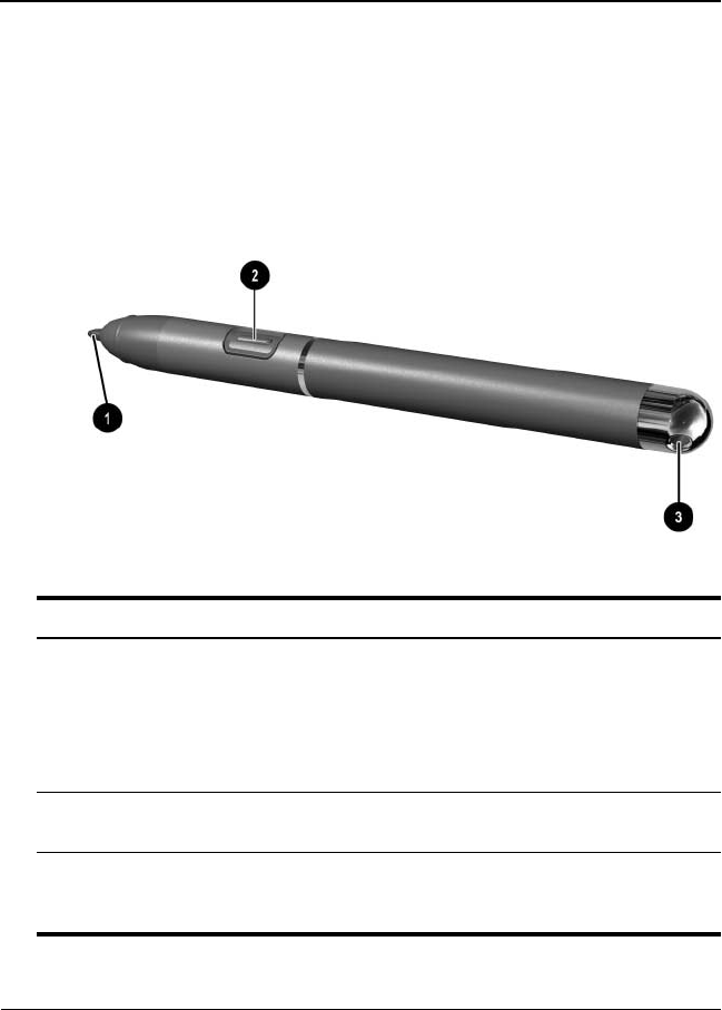
Pen Components
Component Description
1Pen tip Interacts with the tablet PC whenever
the tip is touching the screen or within
1.27 cm (0.5 inch) of the screen.
When tapped on or held over a
pen-activated button, activates the
button.
2Pen button Functions like the right button on an
external mouse.
3Pen tether eyelet Used with the tether eyelet on the
tablet PC, enables you to tether the
pen to the tablet PC.
331734-001.book Page 1 Monday, July 14, 2003 3:47 PM
1–2 Hardware Guide
External Components
Tablet PC Components
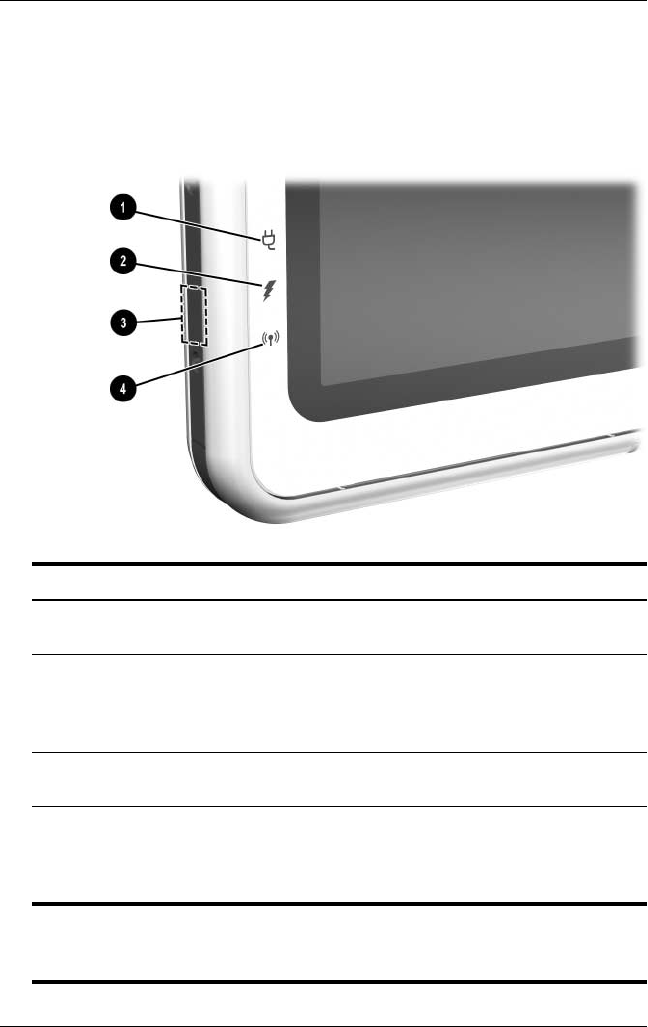
Front: Lights and Bluetooth
Component Description
1AC adapter light On: AC power is being supplied
through the AC adapter.
2Battery light On: A battery pack is charging.
Flashing: A battery pack that is the
only available power source has
reached a low-battery condition.
3Bluetooth antenna Sends and receives Bluetooth*
Integrated Wireless signals.†
4Wireless activity light On: The wireless mini PCI and/or
Bluetooth are on.
Off: The wireless mini PCI and/ or
Bluetooth are off.
*Bluetooth is not available on all models
†For optimal performance when using Bluetooth, keep the area around the
antenna free from obstructions.
331734-001.book Page 2 Monday, July 14, 2003 3:47 PM
External Components
Hardware Guide 1–3
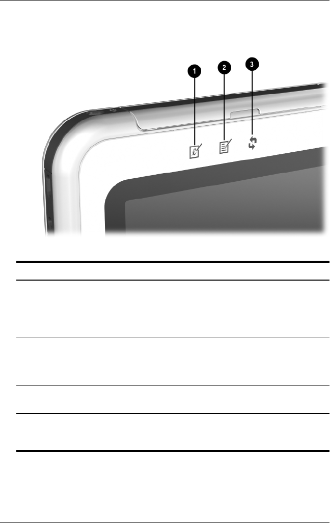
Front: Pen-Activated Buttons
Component Description
1Tablet PC Input Panel launch
button*
When Windows is running, opens the
Microsoft Tablet PC Input Panel
application, which includes a
handwriting pad and an on-screen
keyboard.
2Journal launch button* When Windows is running, opens and
closes the Microsoft Journal
application, which supports
handwriting.
3Rotate button* Switches the image between
landscape and portrait orientation.
*This table describes default settings. For information about changing the
functions of the Tablet PC Input Panel launch, Journal launch, and rotate
buttons, see Chapter 2, “Pen, Command Controls and Keyboards.”
331734-001.book Page 3 Monday, July 14, 2003 3:47 PM
1–4 Hardware Guide
External Components
Right Side: Power Switch and
Power/Standby Light
Component Description
1Power switch* When the tablet PC is:
■Off: Turns on the tablet PC.
■On: Initiates Standby.*
■In Standby: Resumes tablet PC
from Standby.
■In Hibernation: Resumes
tablet PC from Hibernation.*
If the system has stopped responding
and Windows shut down procedures
cannot be used, slide and hold for
4 seconds to turn off the tablet PC.
2Power/standby light On: Tablet PC is on.
Flashing: Tablet PC is in Standby.
Off: Tablet PC is off or in Hibernation.
*This table describes default settings. For information about changing the
functions of the power switch and about using Standby and Hibernation,
refer on this CD to the
Software Guide,
“Power” chapter.
331734-001.book Page 4 Monday, July 14, 2003 3:47 PM
External Components
Hardware Guide 1–5
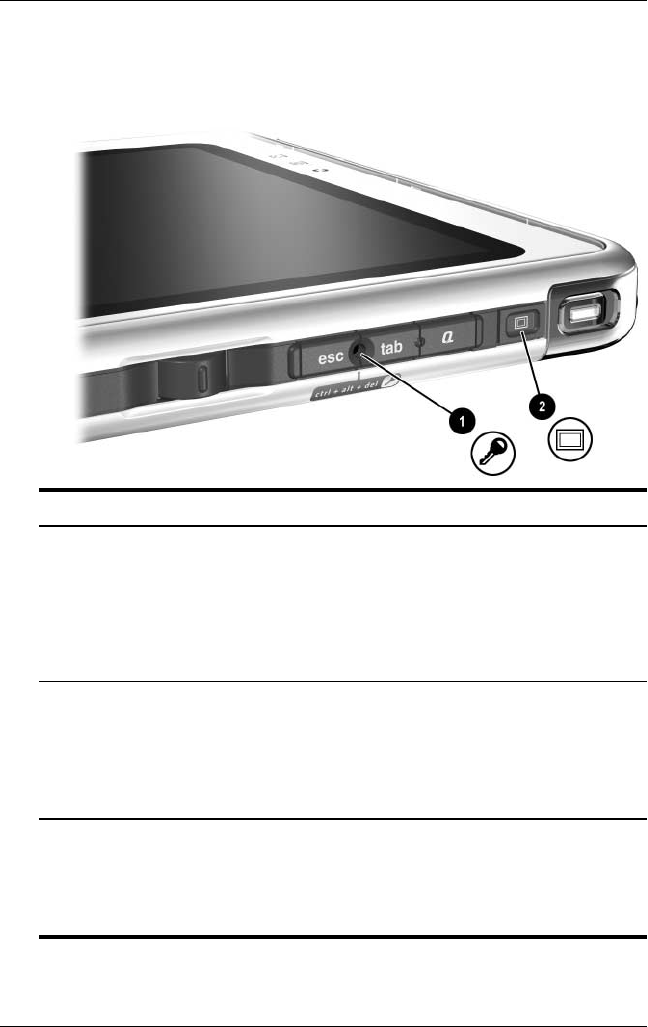
Right Side: Windows Security and
Display Toggle Buttons
Component Description
1Windows Security
button*
When pressed with the pen tip or a small
object like the end of a paper clip while:
■Windows is open, enters the ctrl+alt+delete
command.†
■The Setup utility is open, enters the reset
command.
2Display Toggle
button
When Windows is running, toggles the external
monitor display settings:
■Internal only
■Internal and External
■Extended Desktop
*This table describes default settings. For information about changing the
functions of the Windows Security button, see Chapter 2, “Pen, Command
Controls and Keyboards.”
†To protect your work and the system, the ctrl+alt+delete command cannot
be entered using the Ctrl, Alt, and Del keys on the on-screen keyboard.
331734-001.book Page 5 Monday, July 14, 2003 3:47 PM
1–6 Hardware Guide
External Components
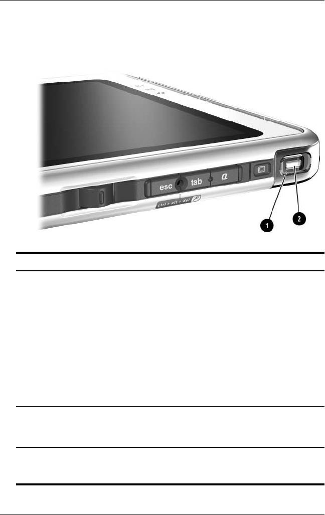
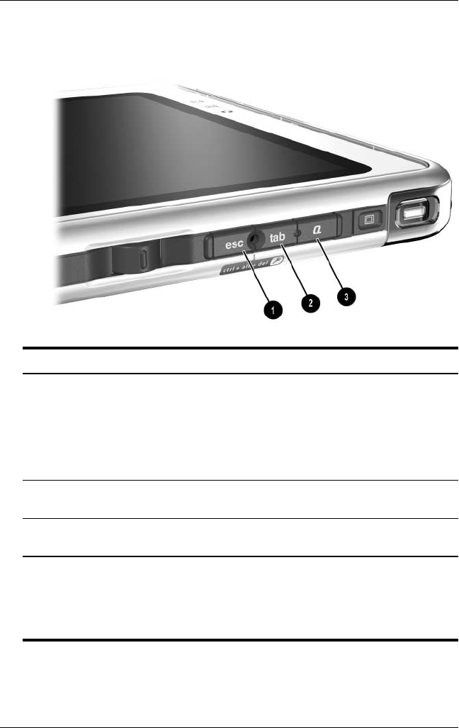
Right Side: Esc, Tab and Q Menu Buttons
Component Description
1Esc button* While the tablet PC is:
■Starting up and a flashing pointer
is displayed on the screen, opens
the Setup utility.
■In Windows, functions like esc on
a standard keyboard.
2Tab button* When Windows is running, functions
like tab on a standard keyboard.†
3Q menu button* When Windows is running, opens or
closes the Q Menu.
*This table describes default settings. For information about changing the
functions of the esc, tab, and Q menu buttons, see Chapter 2, “Pen,
Command Controls and Keyboards.”
†The tab button can also be used, instead of an F12 command, to respond
to a Network Service Boot prompt during startup.
331734-001.book Page 6 Monday, July 14, 2003 3:47 PM
External Components
Hardware Guide 1–7
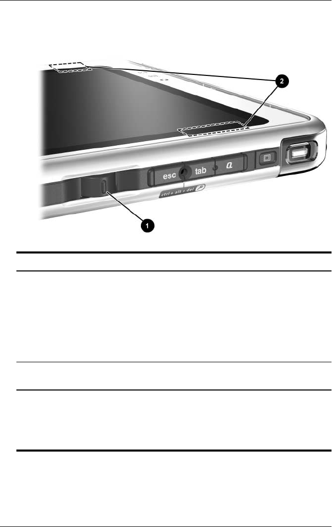
Right Side: Jog Dial and Antenna
Component Description
1Jog dial* Functions like enter and the up and
down arrow keys on a standard
keyboard.
■Press inward to enter a command.
■Rotate upward to scroll upward.
■Rotate downward to scroll
downward.
2Antennas, not visible from
the outside of the tablet PC
Sends and receives internal wireless
LAN signals.†
*This table describes default settings. For information about changing the
rotation functions of the jog dial, see Chapter 2, “Pen, Command Controls
and Keyboards.”
†For optimal performance, keep the antennas free from obstructions while
you are using an internal wireless LAN.
331734-001.book Page 7 Monday, July 14, 2003 3:47 PM
1–8 Hardware Guide
External Components
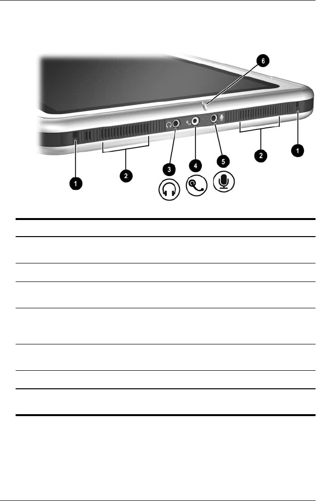
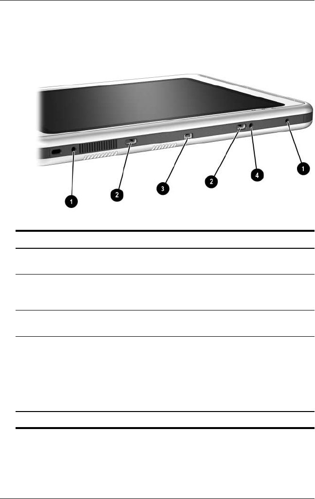
Lower Side
Component Description
1Docking alignment slots (2) Secure the tablet PC to an optional
Tablet PC Docking Station.
2Speakers (2) Produce stereo sound.
3Audio-out jack Connects optional stereo headphones
or powered stereo speakers.
4Headset jack Connects an optional headset, such as
a mobile telephone headset with a
microphone and a monaural ear piece.
5Microphone jack Connects an optional monaural or
stereo microphone.
6Microphone Inputs monaural sound.*
*If you are using speech recognition or other software that requires optimal
sound quality, you must use an optional external microphone or a headset.
331734-001.book Page 8 Monday, July 14, 2003 3:47 PM
External Components
Hardware Guide 1–9
Left Side: Attachment Slots and
Keyboard Connector
Component Description
1Screen protector slots (2) Secure the screen protector* when it is
attached to the tablet PC.
2Universal attachment
slots (2)
Secure the portfolio, a screen
protector*, or an attachment, such as a
tablet PC keyboard, to the tablet PC.
3Keyboard connector Connects the tablet PC keyboard to
the tablet PC.
4Alignment key slot Accepts an alignment key to safeguard
attachment procedures. For example,
matching the alignment key on the
tablet PC keyboard to the alignment
key slot helps you correctly orient the
tablet PC to the keyboard as you
attach the tablet PC to the keyboard.
*A screen protector is included with an optional Tablet PC Docking Station.
331734-001.book Page 9 Monday, July 14, 2003 3:47 PM
1–10 Hardware Guide
External Components
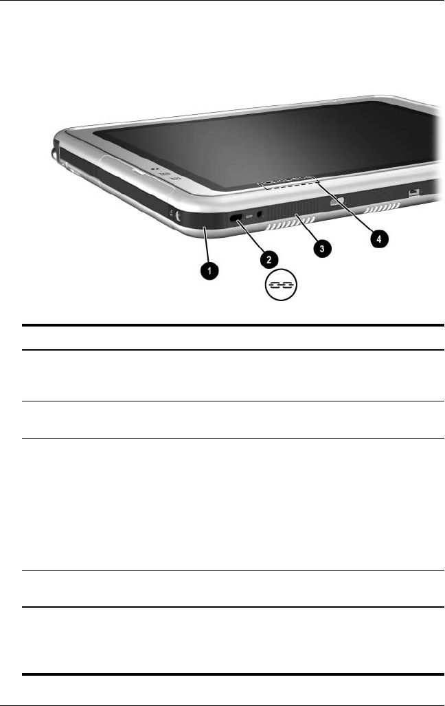
Left Side: Security Cable Slot, Vent and
Antenna
Component Description
1IrDA Fast Infrared Port Transmits and receives infrared
transmissions between the tablet PC
and other infrared devices.
2Security cable slot Attaches an optional security cable to
the tablet PC.
3Vent Allows airflow to cool internal
components.
ÄTo prevent overheating, do
not obstruct the vent. Do not
allow a hard surface, such as
an adjoining optional printer,
or fabric, such as bedding or
clothing, to block airflow.
4Antenna*, not visible from the
outside of the tablet PC
Receives internal wireless LAN
signals.†
*The tablet PC has 2 antennas. The other antenna is found on the right side
of the tablet PC.
†For optimal performance, keep the antennas free from obstructions while
you are using an internal wireless LAN.
331734-001.book Page 10 Monday, July 14, 2003 3:47 PM
External Components
Hardware Guide 1–11
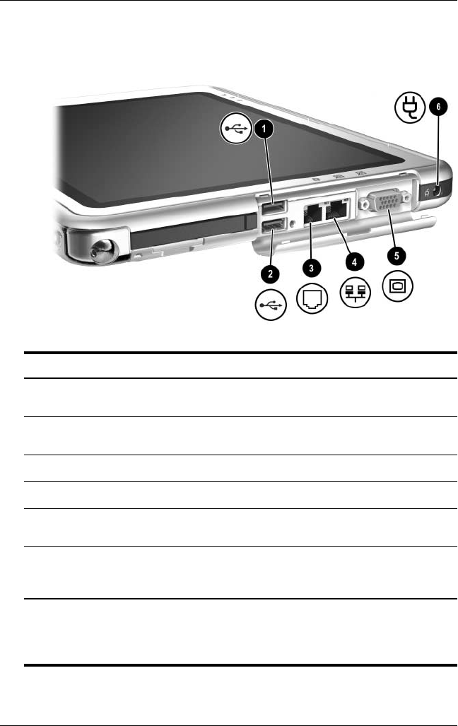
Top: Connectors and Jacks
Component Description
1USB connector Connects an optional USB 2.0- or
1.1-compliant device.*
2External MultiBay
connector
Connects an optional USB 2.0- or
1.1-compliant device.*
3RJ-11 telephone jack Connects a modem cable.
4RJ-45 network jack Connects an Ethernet network cable.
5External monitor
connector
Connects an optional VGA external monitor
or projector.
6AC power connector Connects an AC adapter or an optional
DC cable, Auto/Air Cable, or Automobile
Power Adapter/Charger.
*If an optional External MultiBay is connected to the USB connector, the
External MultiBay must also be connected to external power. If an External
MultiBay is connected to the External MultiBay connector, it is not
necessary to connect the External MultiBay to external power.
331734-001.book Page 11 Monday, July 14, 2003 3:47 PM
1–12 Hardware Guide
External Components
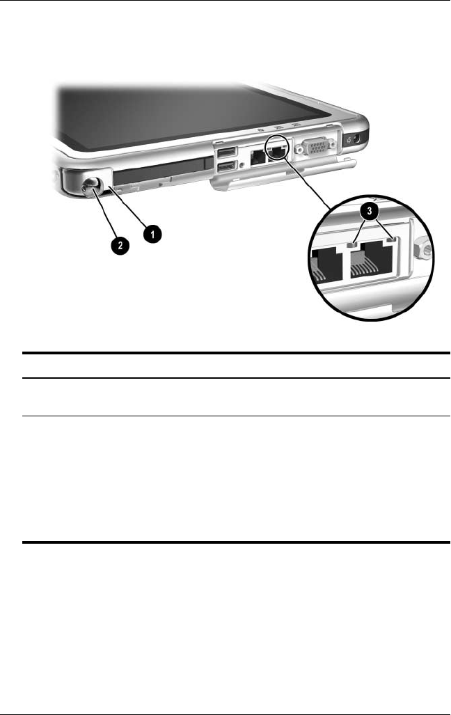
Top: Pen Holder and LAN Connection Lights
Component Description
1Pen holder (shown with
pen 2 inserted)
Secures the pen to the tablet PC.
3LAN connection lights (2) Both lights off: The tablet PC is not
connected to a LAN.
Both lights on: The tablet PC is
connected to a LAN with a
100 Mbps link.
Green light on and yellow light off: The
tablet PC is connected to a LAN with a
10 Mbps link.
331734-001.book Page 12 Monday, July 14, 2003 3:47 PM
External Components
Hardware Guide 1–13
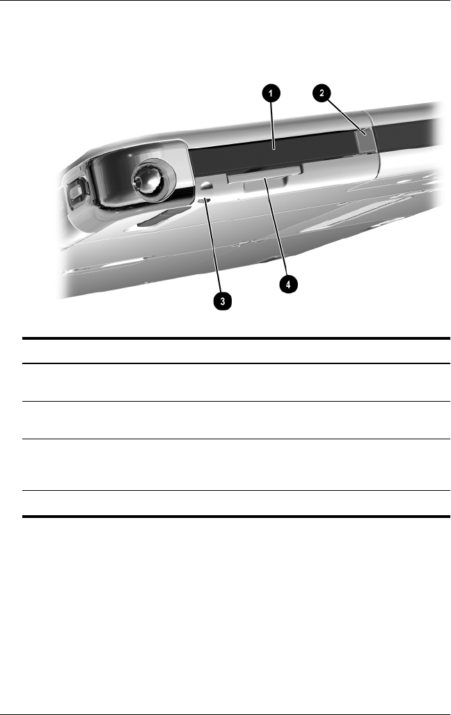
Top: Card Slots, Buttons and Tether Eyelet
Component Description
1PC Card slot Supports an optional Type I or Type II
32-bit (CardBus) or 16-bit PC Card.
2PC Card eject button Ejects an optional PC Card from the
PC Card slot.
3Tablet PC tether eyelet Used with the tether eyelet on the pen,
enables you to tether the pen to the
tablet PC.
4SD (Secure Digital) Card slot Supports an optional SD Card.
331734-001.book Page 13 Monday, July 14, 2003 3:47 PM
1–14 Hardware Guide
External Components
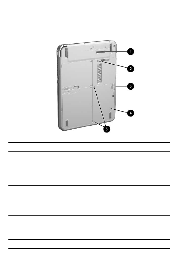
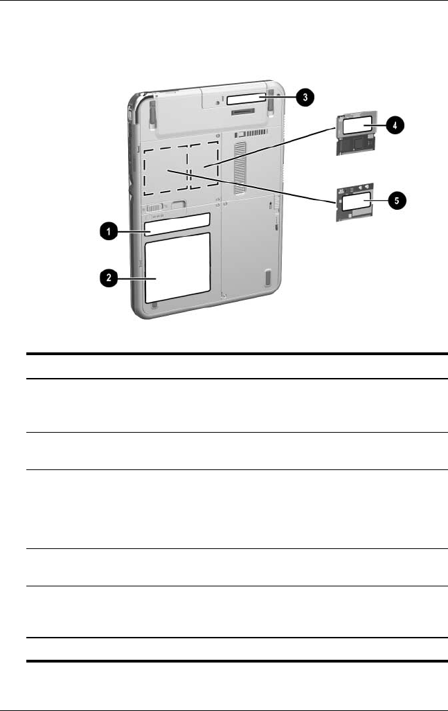
Back: Attachment Features and Hard
Drive Bay
Component Description
1Docking connector Connects the tablet PC to an optional
Docking Station.
2Docking restraint latch
recess
Accepts the docking restraint latch on
an optional Docking Station to secure
the tablet PC to the Docking Station.
3Attachment release switch Releases an attachment, such as the
portfolio, a screen protector*, or an
optional tablet PC keyboard, from
the universal attachment slots on the
tablet PC.
4Hard drive bay Holds the system hard drive.
5Hard drive bay retaining
screws (2)
Secure the hard drive bay cover to the
tablet PC.
*A screen protector is included with an optional Tablet PC Docking Station.
331734-001.book Page 14 Monday, July 14, 2003 3:47 PM
External Components
Hardware Guide 1–15
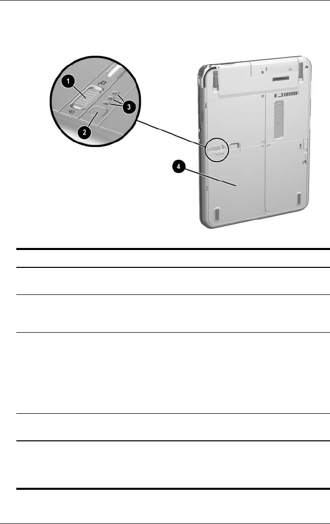
Back: Battery Bay
Component Description
1Battery pack release latch Releases the battery pack from the
battery bay.
2Battery quick check button on
battery pack*
Activates the battery quick check lights
(see below) which display how much
charge remains in the battery pack.
3Battery quick check lights (3)
on battery pack*
On: Each light represents a percent of
a full charge. For example, when all
3 lights are on, the battery pack is fully
charged.
Flashing: When one light is flashing,
less than 5 percent of a full charge
remains in the battery pack.
4Battery bay Holds the battery pack. Also, contains
one battery pack security screw.*
*This illustration shows the battery pack inserted in the battery bay. The
battery pack is included with the tablet PC, but is not inserted. For insertion
instructions and information about using a battery pack security screw for
protection against theft, see Chapter 3, “Battery Packs.”
331734-001.book Page 15 Monday, July 14, 2003 3:47 PM
1–16 Hardware Guide
External Components
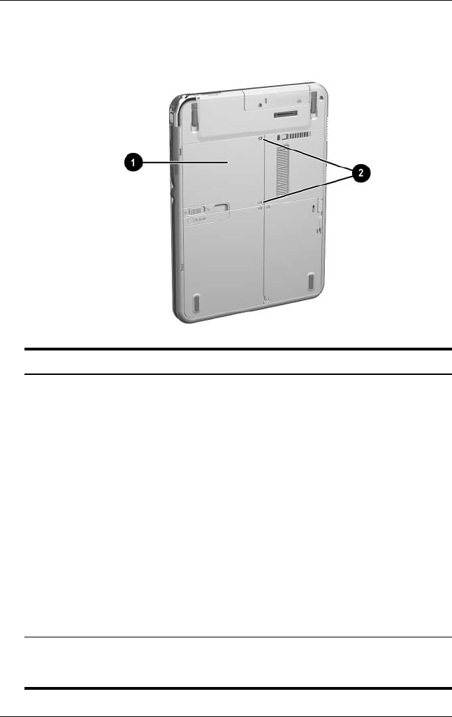
Back: Memory and Mini PCI Compartment
Component Description
1Memory and mini PCI
(Peripheral Component
Interconnect)
compartment, not visible
from the outside of the
tablet PC
Contains one memory slot for a
PC133-compliant memory module.
Also, holds an optional mini PCI board
such as a wireless board. (A mini PCI
board is included with some tablet PC
models.)
ÄThe FCC does not allow unauthorized
mini PCI devices to be used in the
tablet PC. Installing an unsupported
mini PCI device can prevent your
tablet PC from operating properly and
may result in a warning message. To
resume proper operation, remove the
unauthorized device. Contact your
HP Customer Care Center if a
warning message about your
mini PCI device displays in error.
2Memory and mini PCI
compartment retaining
screws (2)
Secure the memory and mini PCI
compartment cover to the tablet PC.
331734-001.book Page 16 Monday, July 14, 2003 3:47 PM
External Components
Hardware Guide 1–17
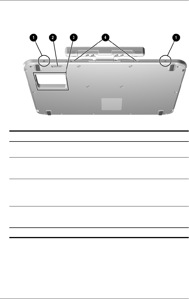
Back: Labels
Component Description
1Microsoft Certificate of
Authenticity label (inside
the battery bay)
Contains the Product Key number.
You may need this number to update or
troubleshoot the operating system.
2System label Provides regulatory information about
the tablet PC.
3Product identification label Contains the serial number of the
tablet PC and a code describing the
original configuration of the tablet PC.
You will need the serial number if you
call HP Customer Care.
4Modem approvals label Lists the countries in which the modem
has been approved for use.*
5Wireless certification label
(on mini PCI wireless
device)
Lists the countries in which the wireless
device has been approved for use.*
*You may need this information when traveling.
331734-001.book Page 17 Monday, July 14, 2003 3:47 PM
1–18 Hardware Guide
External Components
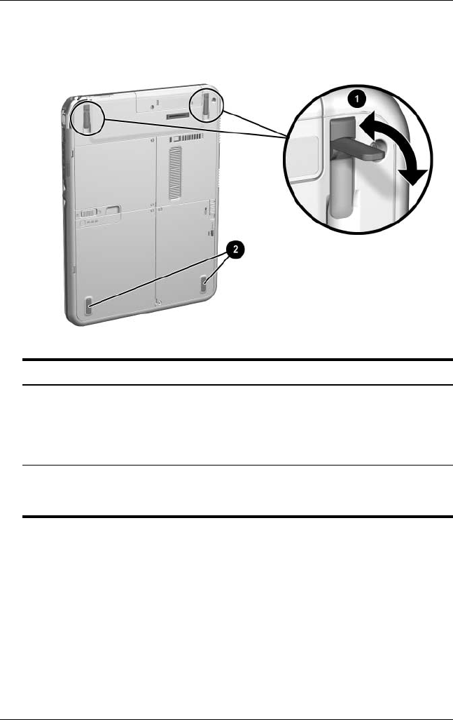
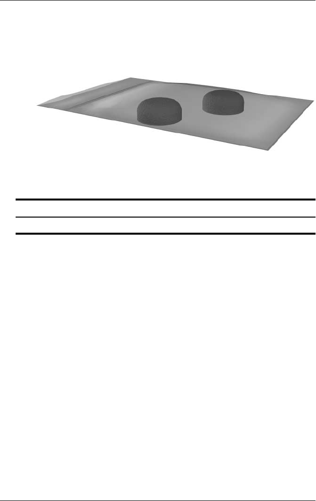
Back: Tilt Feet and Pad Feet
Component Description
1Tilt feet (2) While the tablet PC is being used in
portrait orientation as a free-standing
tablet, can elevate the top of the
tablet PC to provide a comfortable
writing and viewing angle.
2Pad feet (2) Stabilize the tablet PC when the
tablet PC is placed as a free-standing
tablet on a flat surface.
331734-001.book Page 18 Monday, July 14, 2003 3:47 PM

External Components
Hardware Guide 1–19
Additional Tablet PC Standard
Components
The components included with the tablet PC vary by geographical
region and the tablet PC hardware ordered. The following
illustrations and tables identify the standard external components
included with most tablet PC models.
These illustrations do not include supplementary documentation,
supplementary CDs, the portfolio that shipped attached to the
tablet PC or an optional keyboard, or optional devices such as
PC Cards or drives. The system hard drive ships inside the hard
drive bay.
331734-001.book Page 19 Monday, July 14, 2003 3:47 PM

1–20 Hardware Guide
External Components
Documentation CDs
Among the CDs included are:
■Documentation Library CD, which includes product-specific
documentation for the tablet PC, along with modem,
networking, safety, and regulatory information.
For information about using the Documentation Library CD,
refer to the printed Startup Guide included with the tablet PC.
■Documentation Library Wireless LAN CD, which includes
documentation on the wireless devices available for the
tablet PC.
■Documentation Library Bluetooth CD, which includes the
guides and software for Bluetooth wireless connection.
✎Wireless information may vary depending upon the exact
configuration of your tablet PC.
331734-001.book Page 20 Monday, July 14, 2003 3:47 PM
External Components
Hardware Guide 1–21
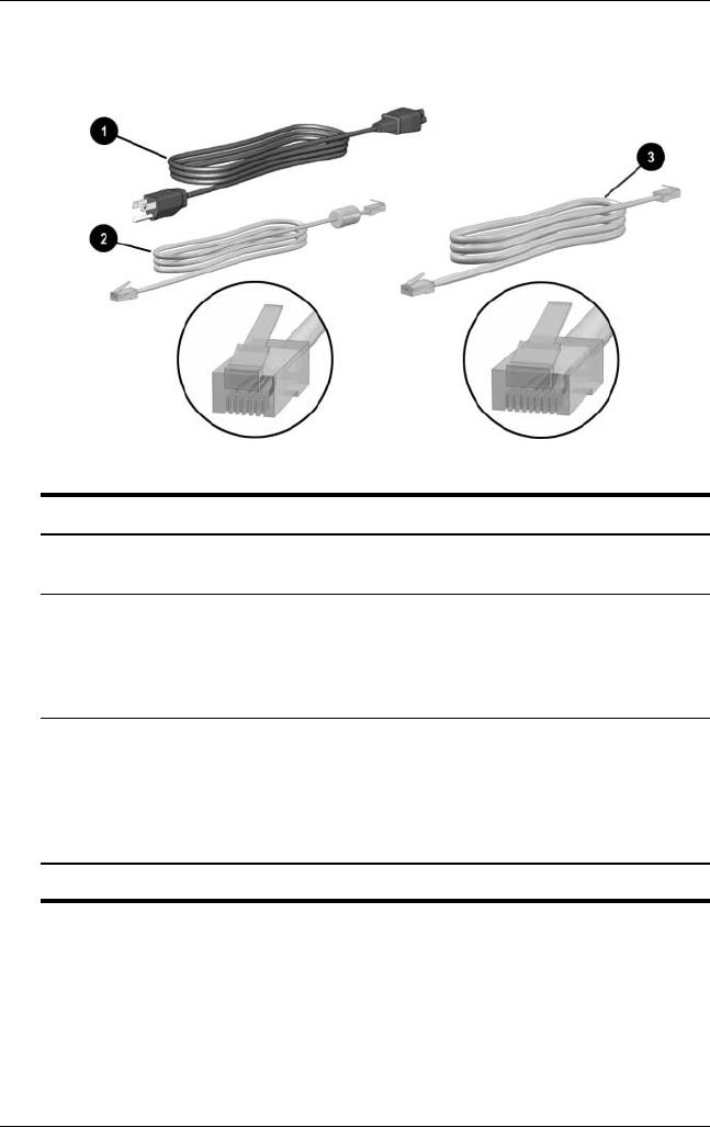
Cords and Cables
Component Description
1Power cord* Connects the AC adapter to an AC electrical
outlet.
2Modem cable Connects the modem to an RJ-11 telephone
jack or to a country-specific modem adapter.
✎The modem cable has a
6-pin
RJ-11
telephone connector at each end.
3Network cable Connects the tablet PC to an RJ-45 (Ethernet
network) jack. (A network cable is included
with network models only.)
✎The network cable has an
8-pin
RJ-45
network connector at each end.
*Power cords vary in appearance by region.
331734-001.book Page 21 Monday, July 14, 2003 3:47 PM
1–22 Hardware Guide
External Components
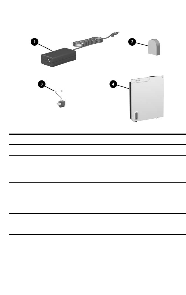
Adapters and Accessories
Component Description
1AC adapter* Converts AC power to DC power.
2Country-specific modem
adapter (included by region
as required with modem
models only)
Adapts the modem cable to a
non-RJ-11 telephone jack.
3Japan-specific outlet adapter
(Japan only)
Connects the AC adapter to a 2-prong
electrical outlet.
4Battery pack Runs the tablet PC when the tablet PC
is not connected to external power.
*AC adapters vary in appearance by region. The only AC adapter that
should be used with the tablet PC is the AC adapter included with the
tablet PC or a replacement AC adapter provided by HP.
331734-001.book Page 22 Monday, July 14, 2003 3:47 PM
External Components
Hardware Guide 1–23
Tablet PC Keyboard Components
This section identifies the hardware components of an optional
tablet PC keyboard.
■For information about detaching, attaching, and adjusting the
keyboard, see Chapter 8, “External Device Connections.”
■For information about using the keyboard, see Chapter 2,
“Pen, Command Controls and Keyboards.”
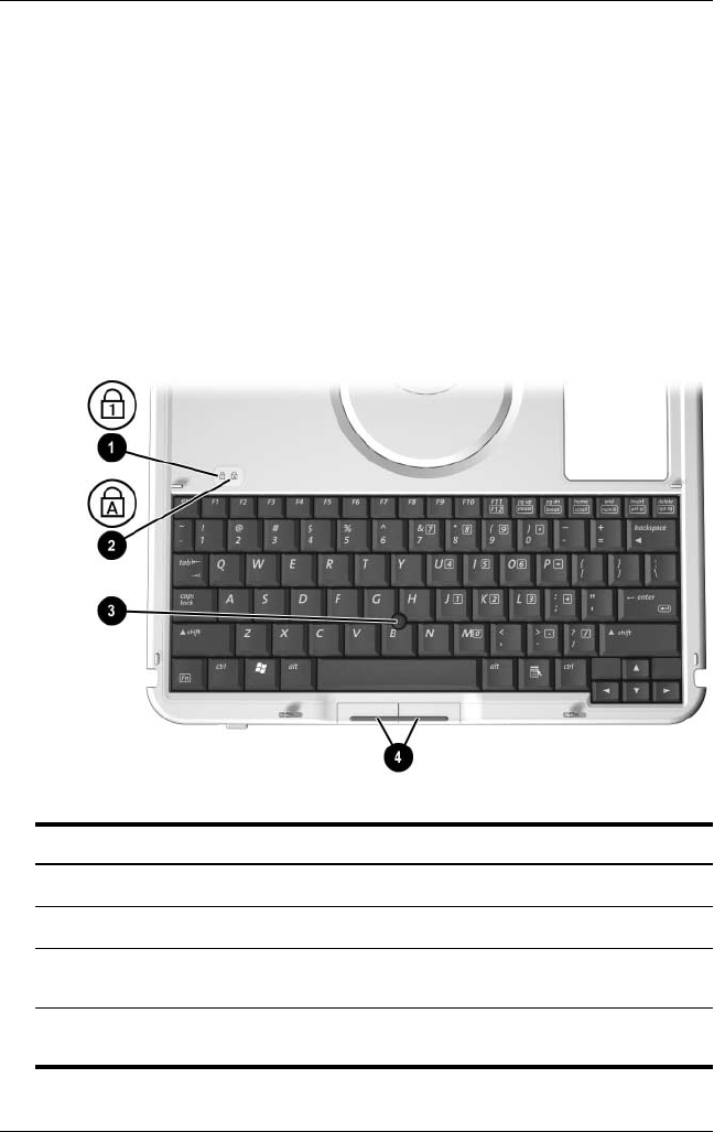
Front: Lights and Pointing Device
Component Description
1Num lock light On: The keypad is on.
2Caps lock light On: Caps lock is on.
3Pointing stick Moves the pointer and selects and
activates items on the screen.
4Left and right pointing stick
buttons
Function like the left and right buttons
on an external mouse.
331734-001.book Page 23 Monday, July 14, 2003 3:47 PM
1–24 Hardware Guide
External Components
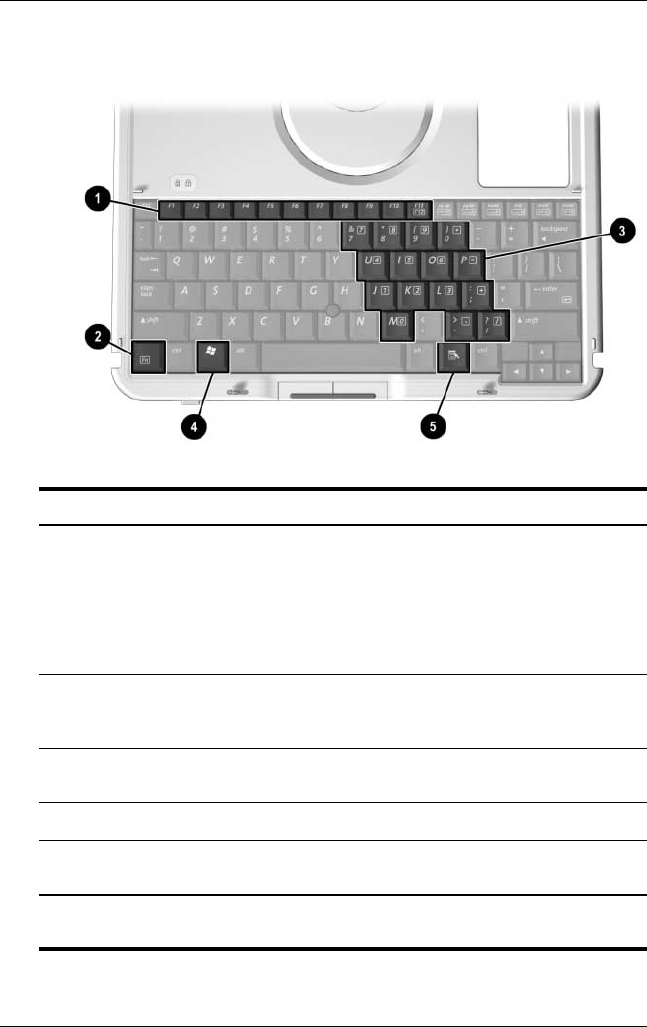
Front: Keys
Component Description
1Function keys (11) Perform system and application tasks. For
example, in Windows and many applications,
pressing F1 opens a Help file.
■To enter an F11 function, press F11/F12.
■To enter an F12 function, press
Fn+F11/F12.
2Fn Combines with other keys to perform system
tasks. For example, pressing Fn+num lk turns
on the keypad.
3Keypad keys (15)* Can be used like the keys on an external
numeric keypad.
4Microsoft logo key Displays the Windows Start menu.
5Applications key Displays a shortcut menu for an item beneath
the pointer.
*For more information about using keypad keys, see Chapter 2, “Pen,
Command Controls and Keyboards.”
331734-001.book Page 24 Monday, July 14, 2003 3:47 PM
External Components
Hardware Guide 1–25
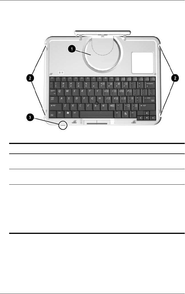
Front: Positioning and Security Features
Component Description
1Rotation disk Rotates the tablet PC while it is
attached to the keyboard.
2Docking alignment
notches (4)
Help guide the tablet PC and keyboard
into an optional Docking Station.
3Keyboard latch When the tablet PC and keyboard are
closed, locks the tablet PC to the
keyboard:
■Slide to the right to lock the
tablet PC to the keyboard.
■Slide to the left to unlock the
tablet PC from the keyboard.
331734-001.book Page 25 Monday, July 14, 2003 3:47 PM
1–26 Hardware Guide
External Components
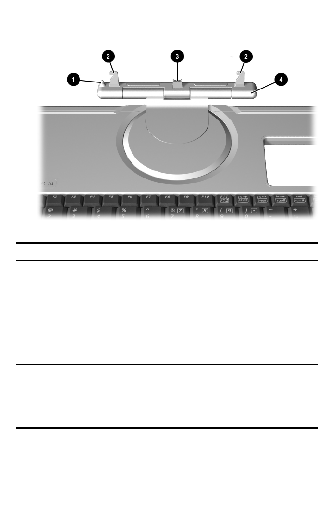
Top
Component Description
1Alignment key Inserts into the alignment key slot on
the tablet PC to safeguard attachment
procedures. For example, matching
the alignment key to the alignment key
slot on the tablet PC helps you
correctly orient the tablet PC to the
keyboard as you attach the tablet PC
to the keyboard.
2Keyboard hooks (2) Secure the tablet PC to the keyboard.
3Keyboard connector Connects the tablet PC to the
keyboard.
4Tilt adjustment Tilts the tablet PC upward or
downward while it is connected to the
keyboard.
331734-001.book Page 26 Monday, July 14, 2003 3:47 PM
External Components
Hardware Guide 1–27
Back
Component Description
1Screen protector slots (2) Secure a screen protector* to the
keyboard.
2Attachment release switch Releases attachments, such as the
portfolio, a screen protector*, or
the tablet PC, from the keyboard.
3Docking connector
pass-through
Allows the tablet PC to be connected
to an optional Docking Station while
the tablet PC is attached to the
keyboard.
4Universal attachment
slots (2)
Secure the portfolio, a screen
protector*, or the tablet PC to the
keyboard.
*A screen protector is included with an optional Tablet PC Docking Station.
331734-001.book Page 27 Monday, July 14, 2003 3:47 PM
1–28 Hardware Guide
External Components
Additional Keyboard Standard Component
Component Description
Spare pointing stick caps (2) Replace a worn pointing stick cap.
331734-001.book Page 28 Monday, July 14, 2003 3:47 PM