HON HAI PRECISION IND J07M067 IBM Intergrated Bluetooth IV with 56K Modem User Manual manual new
HON HAI Precision Ind. Co., Ltd. IBM Intergrated Bluetooth IV with 56K Modem manual new
Users Manual

INSTALLATION MANUAL
J07M067
IBM Integrated Bluetooth IV with 56K Modem

Contents
SECTION ONE: INTRODUCTION............................................................................................1
1.1 FEATURES .............................................................................................................................. 1
1.1.1 BLUETOOTH FUNCTION ............................................................................................................... 1
1.1.2 MODEM FUNCTION ...................................................................................................................... 1
1.2 HARDWARE REQUIREMENTS .......................................................................................................... 2
SECTION TWO: BLUETOOTH INSTALLATION.......................................................................... 3
2.1 BLUETOOTH INSTALLATION ................................................................................................... 3
SECTION THREE: MODEM INSTALLATION...............................................................................7
3.1 DRIVER INSTALLATION .......................................................................................................... 7
3.2 AT COMMANDS ................................................................................................................... 10
SECTION FOUR: FCC NOTICE.................................................................................................15
4.1 FCC COMPLIANCE ............................................................................................................... 15
4.2 FCC CLASS B STATEMENT ................................................................錯誤! 尚未定義書籤。
The information contained in this manual has been verified at the time of this manual printing. The
manufacturer reserves the right to make any changes and improvements in the product described in this
manual at any time and without notice.
All registered trademarks are the property of their respective owners.

Section One: Introduction
The Bluetooth Modem Combo Module is a cost-effective wireless access. The Bluetooth circuit of this
module is compliant to Bluetooth 1.2 standard. With V.92 technology, the modem part can achieve
internet connection rates up to 56 kbits/s with backward compatibility. The V.92 Feature include PCM
Upstream, Modem On Hold, Quick Connection and V.44 Data compression. The Audio CODEC will be
placed on the notebook and contact with Modem Codec by AC-Link Interface. The combo card complies with
MDC Domestic form factor.
1.1 Features
1.1.1 Bluetooth Function
o Bluetooth radio firmware is upgradeable for bug fixes, initial version compatible with Bluetooth
specification version 1.2.
o Fully compliant to Bluetooth SIG (BQB) compatibility testing.
o USB Pin assignment is to use MDC reserve pin to communicate with Host.interface
o Bluetooth Profile Support
- General Access Profile
- Service Discovery Application Profile
- Serial Port Profile
- Dial-up Networking Profile
- LAN Access Profile
- Generic Object Exchange Profile
- File Transfer Profile
- Object Push Profile
- Synchronization Profile
o Drivers support Windows 98, 98SE, ME, 2000, XP.
o Supports Power Management ACPI 1.94 (or later)
o Bluetooth performance must exceed 500 kbps, using OBEX.
1.1.2 Modem Function
o AC’97/MC’97 2.2 compliant
o Support Modem Digital Line Guard: The product shall incorporate circuitry to sense whenever the
current on the line exceeds approximately 130mA, and should immediately go back on hook.
o The call progress signal shall be scaled digitally according to the speaker level setting (ATL1, L2,
L3)
o ITU-T V.92 PCM Upstream and V.90 data rates with auto-fallback to V.34, V.32terbo, V.32bis and
fallbacks

o TIA/EIA 602 standard for AT Command set
o Supports V.42 error correction and V.44, V.42bis/MNP5 data compression
o FAX capabilities: ITU-T V.17, V.29, V.27ter, V.21 Ch2 and TIA/EIA 578 Class1 FAX
o Support Wake up on Ring and meet WHQL test requirement..
1.2 Hardware Requirements
Supply Voltage 3.3V & 1.8V
Frequency Range 2.400-2.4835 GHz
Antenna Load 50 Ohm
Receive Sensitivity –80 dBm@0.1% BER
Maximum Receiver Signal -20 dBm
TX Power 4 dBm maximum (class 2)
RF Power Control Step Size 2 dB
Range 10 meters at 0 dBm TX power (class 2)
Radio Compliant with Bluetooth standard version 1.1
Pico Net 1 master to 7 slaves
Operating Channels 79 channels of 1 MHz BW
Security Full support of Bluetooth security provisions including
hardware support for full length 128 bit encryption keys.
Host Interface (USB) USB specification 1.1 compliant and using MDC reserve pin to
communicate with Host
Software Requirements Windows 98SE, ME, 2000, XP.
Mechanical Requirements 28.5mm x 47mm x 4.6mm(1.3/0.8/2.5mm)
Section Two: Bluetooth Installation
The following steps provide instructions for installing Bluetooth.
1. Make sure your MDC BT/Modem Combo card already insert into your notebook.
2. Make sure your notebook operating system support Windows 98SE or ME or 2000 or XP.
2.1 Bluetooth Installation
Proceed to the following section.
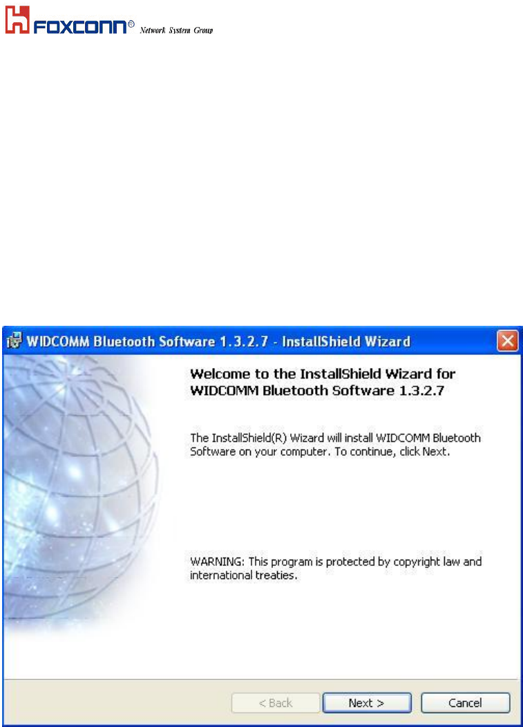
1. Execute the program ‘Setup.exe’ in the CD. Windows displays the dialog as below. Click ‘Next’ to begin the
process.
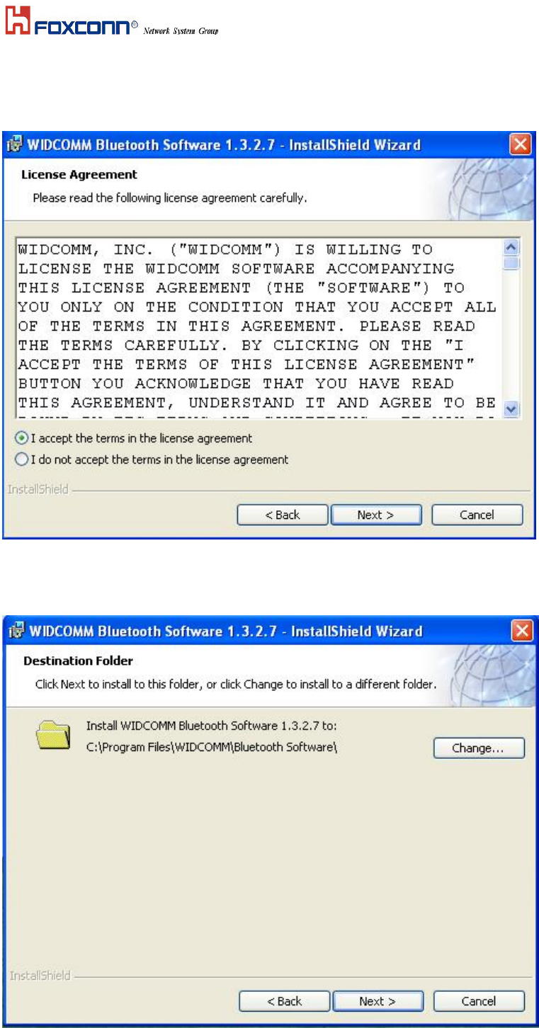
2.The “License Agreement” windows will pop up, please read it carefully. If you agree it, and choose ‘I agree
the terms in the license agreement’ and click on ‘Next’.
3. “Destination Folder” appears, specify the location of the driver and software to be installed then press ‘Next’
bottom.
4. When all the above process are done, it will show ‘Ready to Install the Program” window. Make
sure the driver software is ready to be installed, click ‘Install’.
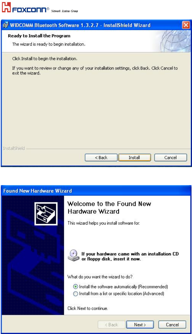
5.Choose ‘Install the software automatically [Recommened]’, then Click ‘Next’ to continue.
6. Congratulations! Bluetooth has been installed successfully.
Please click ‘Finish’ to confirm the completion of installation.
Broadcom USB Bluetooth Device
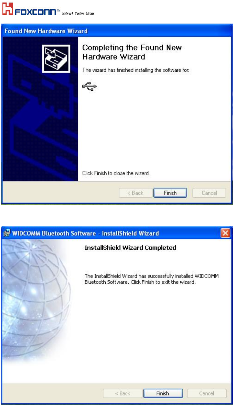
7. Then click ‘Finish’ to exit the InstallShield Wizard.
Broadcom USB Bluetooth Device

Section Three: Modem Installation
The following steps provide instructions for installing your 56K Internal modem.
1. Check the BT/modem Module already inserted into the slot.
2. Insert the connector of RJ-11 cable into the female connector of modem. The connector is keyed and will
no allow incorrect insertion. Plug the other end of the RJ-11 cable into an available phone jack.
3.1 Driver Installation
Your modem is using the Plug and Play (PnP) capabilities of you computer. PnP is a set of specifications that
define the ability for the computer hardware and operating system to automatically configure all compliant
devices that are installed, relieving the user of the need to determine which addresses and interrupts to user for
each device.
Proceed to the following section.
1. Start Windows 98, an “PCI Card” dialog with drive selected will appear. Click “Next”
2. Search for the best driver for Modem card and click Next to continue.
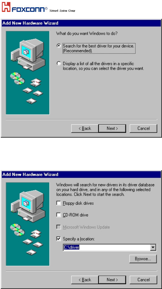
3 Please release your driver to “c:\driver” or any specific location you want.
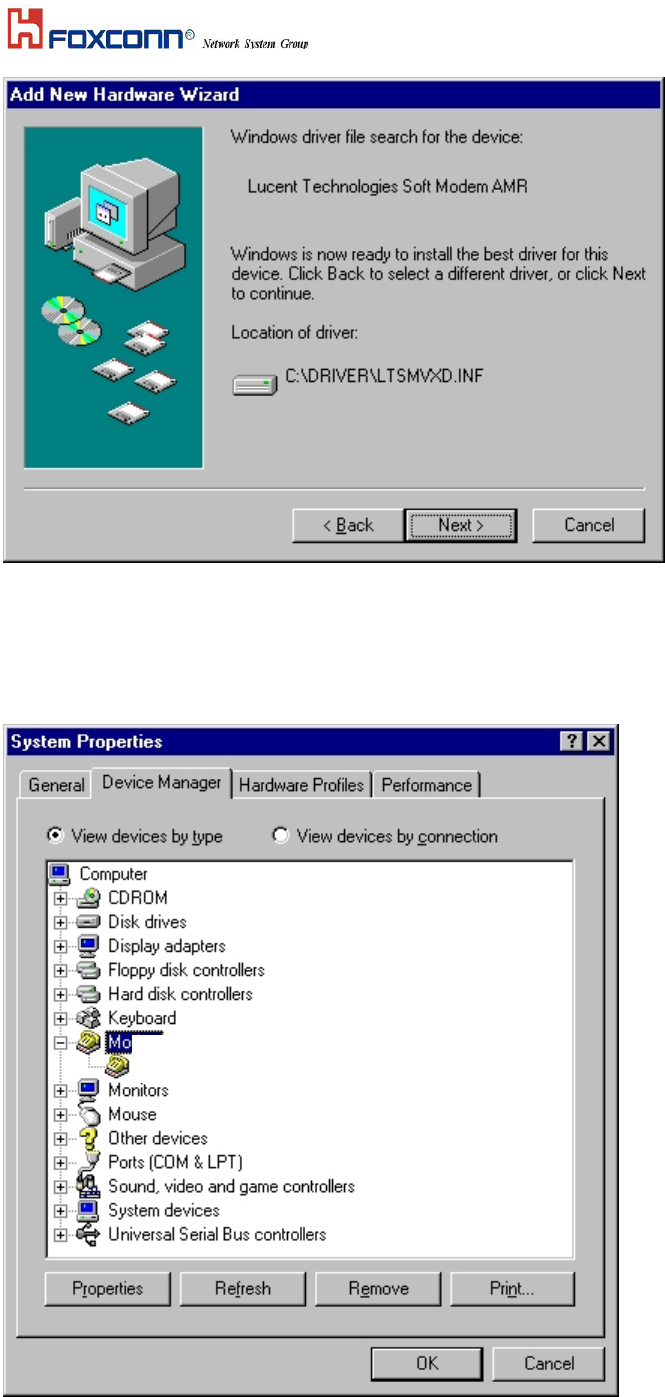
4. After Windows finishes loading, select My Computer\Control Panel\System\Device Manager. If
you can see the modem device on this Device Manager, then you already complete the Modem Driver
installation.
IBM Integrated 56K modem

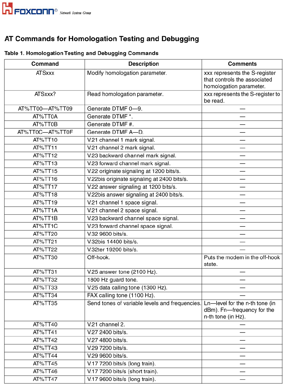
3.2 AT Commands
Basic AT Commands
A summary of the commands implemented by the modem are shown in Table1. Commands may be executed
when the modem is in COMMAND mode. COMMAND mode is entered upon one of the following conditions:
After power up.
At the termination of a connection.
After the execution of a command other than dial or answer commands (ATO or AT&T).
Upon the receipt of the ESCAPE SEQUENCE (three consecutive characters matching the contents of S register
2) while online mode.
Upon the on-to-off transition of DTR if D1, &D2, or &D3 has been set.
AT Commands
Basic AT Commands
Command Function Command Function
A/ Re-execute command A Go off-hook and attempt to answer a call
B0 Select V.22 connect @1200 bps B1 Select Bell 212A connect @1200 bps
C1 Return OK message Dn Dial modifier
E0 Turn off command echo E1 Turn on command echo
H0 Initiate a hang-up sequence H1 If on-hook, go off-hook and enter
I0 Report product code command mode
I1 Report pre-computed checksum I2 Report “OK” if the calculated checksum
I3 Report firmware revision, model, equals the prestored checksum or if the
and interface type prestored checksum value is FFh
I4 Report response programmed by OEM I5 Report the country code parameter
I6 Report modem data pump model I7 Report the DAA code
and code revision L0 Set low speaker volume
L1 Set low speaker volume L2 Set medium speaker volume
L3 Set high speaker volume M0 Turn speaker off
M1 Turn speaker on during handshaking M2 Turn speaker on during handshaking and
and turn speaker off while receiving while receiving carrier
carrier M3 Turn speaker off during dialing and
N0 Turn off auto mode detection receiving carrier and turn speaker on
N1 Turn on auto mode detection during answering
P Force pulse dialing Q0 Allow result codes to DTE
Q1 Inhibit result codes to DTE Sn Select S-Register n as default
Sn? Return the value of S-Register n Sn=v Set default S-Register n to value v
T Force DTMF dialing
V0 Report short form result codes V1 Report long form result codes
W0 Report DTE speed only W1 Report line speed, EC protocol and DTE
W2 Report DCE speed only speed
X0 Report basic call progress result codes, X1 Report basic call progress result codes
i.e., Ok, Connect, Ring, No Carrier and connections speeds (Ok, Connect,
(also, for busy, if enabled, and dial tone Ring, No Carrier (also, for busy, if
not detected), No Answer and Error enabled, and dial tone not detected), No
X2 Report basic call progress result codes Answer, Connect XXXX, and Error
and connections speeds, i.e., Ok, X3 Report basic call progress result codes
Connect, Ring, No Carrier (also, for and connections rate, i.e., Ok, Connect,
busy, if enabled, and dial tone not Ring, No Carrier, No Answer, Connect
detected), No Answer, Connect XXXX, XXXX, Busy, and Error
and Error Y0 Disable long space disconnect before on-
X4 Report all call progress result codes hook
and connections rate, i.e., Ok, Connect,
Ring, No Carrier, No Answer, Connect
XXXX, Busy, No Dial Tone and Error Z0 Restore stored profile 0 after warm reset
Z1 Soft reset and restore stored profile 1 &C0 Soft reset and force RLSD active
after warm reset regardless of the carrier state
&C1 Allow RLSD to follow the carrier state
&D0 Interpret DTR On-to-OFF transition &D1 Interpret DTR On-to-OFF transition

per &Qn per &Qn
&Q0, &Q5, &Q6 The modem ignores DTR &Q0, &Q1, &Q4, &Q5, &Q6 Asynchronous escape
&Q1, &Q4 The modem hangs up &Q2, &Q3 The modem hangs up
&Q2, &Q3 The modem hangs up
&D2 Interpret DTR On-to-OFF transition &D1 Interpret DTR On-to-OFF transition
per &Qn per &Qn
&Q0 through &Q6 The modem hangs up &Q0, &Q1, &Q4, &Q5, &Q6 Soft reset
&Q2, &Q3 The modem hangs up
&F0 Restore factory configuration 0
&G0 Disable guard tone &G1 Disable guard tone
&G2 Enable 1800 Hz guard tone &J0 Set S-Register response only for com-
patibility
&K0 Disable DTE/DCE flow control
&K3 Enable RTS/CTS DTE/DCE flow &K4 Enable XON/XOFF DTE/DCE flow
control control
&K6 Enable both RTS/CTS and XON/XOFF&M0 Select direct asynchronous mode
flow control
&P0 Set 10 pps pulse dial with 39%/61%
make/break
&P1 Set 10 pps pulse dial with 33%/67% &P2 Set 20 pps pulse dial with 39%/61%
make/break make/break
&Q0 Select direct asynchronous mode
&Q5 Modem negotiates an error corrected &Q6 Select asynchronous operation in normal
link mode
&R0 CTS tracks RTS (sync) or CTS is &R1 CTS is always active (sync) or CTS is
normally ON and will turn OFF normally ON and will turn OFF
only if required by flow control (async) only if required by flow control (async)
&S0 DSR is always active &S1 DSR will become active after answer
&T0 Terminate any test in progress tone has been detected and inactive after
&T1 Initiate local analog loop back the carrier has been lost
&T2 Returns ERROR result code &T3 Initiate local digital loop back
&V Display current configuration and &W0 Store the current configuration as
stored profiles profile 0
&Y0 Recall stored profile 0 upon power up
&Zn=x Store dial string x (up to 34 digits) %E0 Disable line quality monitor and auto
to location n (0 to 3) retrain
%E1 Enable line quality monitor and auto %E2 Enable line quality monitor and fallback/
retrain fall forward
When modem receives a break from the DTE:
\K0,2,4 Enter on-line command mode, no \K1 Clear buffers and send break to remote
break sent to the remote modem modem
\K3 Send break to remote modem \K5 Send break to remote modem in sequence
immediately with transmitted data
When modem receives \B in on-line command state:
\K0,1 Clear buffers and send break to remote \K2,3 Send break to remote modem immediately
modem
\K4,5 Send break to remote modem in sequence with transmitted data
When modem receives break from the remote modem:
\K0,1 Clear data buffers and send break to \K2,3 Send a break immediately to DTE
DTE \K4,5 Send a break with received data to the
DTE
\N0 Select normal speed buffered mode \N1 Select direct mode
\N2 Select reliable link mode \N3 Select auto reliable mode
\N4 Force LAPM mode \N5 Force MNP mode
\V0 Connect messages are controlled \V1 Connect messages are displayed in the
by the command settings X, W, and S95 single line format
+MS Select modulation +H0 Disable Rockwell Protocol Interface (RPI)
+H1 Enable RPI and set DTE speed to /Video ready mode
19200 bps +H2 Enable RPI and set DTE speed to 38400 bps
+H3 Enable RPI and set DTE speed to +H11 Enable RPI+ mode
57600 bps +H16 Enable Video Ready mode

**0 Download to flash memory at last **1 Download to flash memory at 38.4 kbps
sensed speed **2 Download to flash memory at 57.6 kbps
-SDR=0 Disable distinctive ring -SDR=1 Enable distinctive ring type 1
-SDR=2 Enable distinctive ring type 2 -SDR=3 Enable distinctive ring type 1 and 2
-SDR=4 Enable distinctive ring type 3 -SDR=5 Enable distinctive ring type 1 and 3
-SDR=6 Enable distinctive ring type 2 and 3 -SDR=7 Enable distinctive ring type 1, 2 and 3
ECC Commands
%C0 Disable data compression %C1 Enable MNP 5 data compression
\A0 Set maximum block size in MNP to 64 \A1 Set maximum block size in MNP to 128
\A2 Set maximum block size in MNP to 192 \A3 Set maximum block size in MNP to 256
\Bn Send break of n x 100 ms
MNP 10 Commands
-K0 Disable MNP 10 extended services -K1 Enable MNP 10 extended services
-K2 Disable MNP 10 extended services -SEC=0 Disable MNP 10-EC
detection only
-SEC=1, [<tx level>] Enable MNP 10-EC and set transmit level<tx level> 0 to 30 (0 dBm to -30 dBm)
FAX Class 1
+Fclass=1 Service class +FAE=0 Disable data/fax auto answer
+FAE=1 Enable data/fax auto answer +FRH=n Receive data with HDLC framing
+FRM=n Receive data +FRS=n Receive silence, nx10 ms
+FTH=n Transmit data with HDLC framing +FTM=n Transmit data
+FTS=n Stop transmission and wait, nx10 ms
V.92 Command set
1.AT%TT61 V.92 generate V.92 PCM upstream signal for PTT testing.
2.AT+PQC=255 to clear all stored fast connect profiles.
S-Registers
Register Function Range/units Default

S0 Rings to auto-answer 0-255/rings 0
S1 Ring counter 0-255/rings 0
S2 Escape character 0-255/ASCII 43
S3 Carriage return character 0-127/ASCII 13
S4 Line feed character 0-127/ASCII 10
S5 Backspace character 0-255/ASCII 8
S6 Wait time for dial tone 2-255/s 2
S7 Wait time for carrier 1-255/s 50
S8 Pause time for dial delay modifier 0-255/s 2
S9 Carrier detect response time 1-255/.1 s 0
S10 Carrier loss disconnect time 1-255/.1 s 20
S11 DTMF tone duration 50-255/.001 s 95
S12 Escape prompt delay 0-255/.02 s 50
S14 General bit mapped options status 8 (8h)
S16 Test mode bit mapped options status (&T) 7
S18 Test timer 0-255/s 0
S19 Auto Sync options 0
S20 Auto Sync HDLC address or BSC 0-255 0
Sync character
S21 V.24/general bit mapped options status 48 (30h)
S22 Speaker/results bit mapped options status 112 (70h)
S23 General bit mapped options status 0
S24 Sleep inactivity timer 0-255/s 10
S25 Delay to DTR off 0-255/s or .01s 0
S26 RTS-to-CTS delay 0-255/.01 s 0
S27 General bit mapped options status 0
S28 General bit mapped options status 0
S29 Flash dial modifier time 0-255/10 ms 0
S30 Disconnect inactivity timer 0-255/10 s 0
S31 General bit mapped options status 0
S32 XON character 0-255/ASCII 10 (Ah)
S33 XOFF character 0-255/ASCII 0
S36 LAPM failure control 7
S37 Line connection speed 0
S38 Delay before forced hang-up 0-255/s 0
S39 Flow control bit mapped options status 0
S40 General bit mapped options status 0
S41 General bit mapped options status 0
S46 Data compression control 0
S48 V.42 negotiation control 7
S82 LAPM break control 0
S86 Call failure reason code 0-255 0
S91 PSTN transmit attenuation level 0-15/dBm 10 (country dependent)
S92 Fax transmit attenuation level 0-15/dBm 10 (country dependent)
S95 Result code messages control 150

Result Code Summary
OK 0 CONNECT 1
RING 2 NO CARRIER 3
ERROR 4 CONNECT 1200 5
NO DIAL TONE 6 BUSY 7
NO ANSWER 8 CONNECT 0600 9
CONNECT 2400 10 CONNECT 4800 11
CONNECT 9600 12 CONNECT 7200 13
CONNECT 12000 14 CONNECT 14400 15
CONNECT 19200 16 CONNECT 38400 17
CONNECT 57600 18 CONNECT 115200 19
CONNECT 230400 20 CONNECT 75TX/1200RX 22
CONNECT 1200TX/75RX 23 DELAYED 24
BLACKLISTED 32 FAX 33
DATA 35 CARRIER 300 40
CARRIER 1200/75 44 CARRIER 75/1200 45
CARRIER 1200 46 CARRIER 2400 47
CARRIER 4800 48 CARRIER 7200 49
CARRIER 9600 50 CARRIER 12000 51
CARRIER 14400 52 CARRIER 16800 53
CARRIER 19200 54 CARRIER 21600 55
CARRIER 24000 56 CARRIER 26400 57
CARRIER 28800 58 CONNECT 16800 59
CONNECT 21600 61 CONNECT 24000 62
CONNECT 26400 63 CONNECT 28800 64
COMPRESSION: CLASS 5 66 COMPRESSION: V.42 bis 67
COMPRESSION: NONE 69 PROTOCOL: NONE 70
PROTOCOL: LAPM 77 CARRIER 31200 78
CARRIER 33600 79 CONNECT 33600 84
CONNECT 31200 91 CARRIER 32000 150
CARRIER 34000 151 CARRIER 36000 152
CARRIER 38000 153 CARRIER 40000 154
CARRIER 42000 155 CARRIER 44000 156
CARRIER 46000 157 CARRIER 48000 158
CARRIER 50000 159 CARRIER 52000 160
CARRIER 54000 161 CARRIER 56000 162
CONNECT 32000 165 CONNECT 34000 166
CONNECT 36000 167 CONNECT 38000 168
CONNECT 40000 169 CONNECT 42000 170
CONNECT 44000 171 CONNECT 46000 172
CONNECT 48000 173 CONNECT 50000 174
CONNECT 52000 175 CONNECT 54000 176
CONNECT 56000 177 +FCERROR +F4
Section Four: FCC Notice
4.1 Federal Communication Commission Interference Statement
This equipment has been tested and found to comply with the limits for a Class B digital device, pursuant to Part
15 of the FCC Rules. These limits are designed to provide reasonable protection against harmful interference
in a residential installation. This equipment generates, uses and can radiate radio frequency energy and, if not
installed and used in accordance with the instructions, may cause harmful interference to radio

communications. However, there is no guarantee that interference will not occur in a particular installation. If
this equipment does cause harmful interference to radio or television reception, which can be determined by
turning the equipment off and on, the user is encouraged to try to correct the interference by one of the following
measures:
-Reorient or relocate the receiving antenna.
-Increase the separation between the equipment and receiver.
-Connect the equipment into an outlet on a circuit different from that to which the receiver is connected.
-Consult the dealer or an experienced radio/TV technician for help.
This device complies with Part 15 of the FCC Rules. Operation is subject to the following two conditions: (1)
This device may not cause harmful interference, and (2) this device must accept any interference received,
including interference that may cause undesired operation.
FCC Caution: Any changes or modifications not expressly approved by the party responsible for compliance
could void the user's authority to operate this equipment.
IMPORTANT NOTE:
FCC Radiation Exposure Statement:
This equipment complies with FCC radiation exposure limits set forth for an uncontrolled environment. This
equipment should be installed and operated with minimum distance 20cm between the radiator & your body.
This transmitter must not be co-located or operating in conjunction with any other antenna or transmitter.
FOXCONN declared that J07M067 is limited in CH1~11 from 2412 to 2462 MHz by specified firmware
controlled in USA.
This device is intended only for OEM integrators under the following conditions:
The antenna must be installed such that 20 cm is maintained between the antenna and users, and
The transmitter module may not be co-located with any other transmitter or antenna.
As long as 2 conditions above are met, further transmitter test will not be required. However, the OEM integrator
is still responsible for testing their end-product for any additional compliance requirements required with this
module installed (for example, digital device emissions, PC peripheral requirements, etc.).
IMPORTANT NOTE: In the event that these conditions can not be met (for example certain laptop
configurations or co-location with another transmitter), then the FCC authorization is no longer considered valid
and the FCC ID can not be used on the final product. In these circumstances, the OEM integrator will be
responsible for re-evaluating the end product (including the transmitter) and obtaining a separate FCC
authorization.
End Product Labeling
This transmitter module is authorized only for use in device where the antenna may be installed such that 20 cm
may be maintained between the antenna and users (for example : Notebook). The final end product must be
labeled in a visible area with the following: “Contains TX FCC ID: MCLJ07M067”.
Manual Information That Must be Included
The OEM integrator has to be aware not to provide information to the end user regarding how to install or
remove this RF module in the users manual of the end product which integrate this module.
The users manual for OEM integrators must include the following information in a prominent location “ IMPORTANT
NOTE: To comply with FCC RF exposure compliance requirements, the antenna used for this transmitter must be installed
to provide a separation distance of at least 20 cm from all persons and must not be co-located or operating in conjunction
with any other antenna or transmitter.
Appendix