HON HAI PRECISION IND J20H018 802.11b/g WLAN Module User Manual
HON HAI Precision Ind. Co., Ltd. 802.11b/g WLAN Module
User Manual
J20H018 Foxconn
WLAN Client Module
IEEE 802.11g/b
802.11b/g WLAN Module
Doc. No. MV-S800245-00, Rev. C
May 26, 2005
CoverF
Document Conventions
Note
Provides related information or information of special importance.
Caution
Indicates potential damage to hardware or software, or loss of data.
Warning
Indicates a risk of personal injury.
Document Status
Doc Status: 2.00 Technical Publication: 0.x
Disclaimer
No part of this document may be reproduced or transmitted in any form or by any means, electronic or mechanical, including photocopying and recording, for any purpose,
without the express written permission of Marvell. Marvell retains the right to make changes to this document at any time, without notice. Marvell makes no warranty of any
kind, expressed or implied, with regard to any information contained in this document, including, but not limited to, the implied warranties of merchantability or fitness for
any particular purpose. Further, Marvell does not warrant the accuracy or completeness of the information, text, graphics, or other items contained within this document.
Marvell products are not designed for use in life-support equipment or applications that would cause a life-threatening situation if any such products failed. Do not use
Marvell products in these types of equipment or applications.
With respect to the products described herein, the user or recipient, in the absence of appropriate U.S. government authorization, agrees:
1) Not to re-export or release any such information consisting of technology, software or source code controlled for national security reasons by the U.S. Export Control
Regulations ("EAR"), to a national of EAR Country Groups D:1 or E:2;
2) Not to export the direct product of such technology or such software, to EAR Country Groups D:1 or E:2, if such technology or software and direct products thereof are
controlled for national security reasons by the EAR; and,
3) In the case of technology controlled for national security reasons under the EAR where the direct product of the technology is a complete plant or component of a plant,
not to export to EAR Country Groups D:1 or E:2 the direct product of the plant or major component thereof, if such direct product is controlled for national security reasons
by the EAR, or is subject to controls under the U.S. Munitions List ("USML").
At all times hereunder, the recipient of any such information agrees that they shall be deemed to have manually signed this document in connection with their receipt of
any such information.
Copyright © 2005. Marvell International Ltd. All rights reserved. Marvell, the Marvell logo, Moving Forward Faster, Alaska, Fastwriter, GalNet, Libertas, Link Street, NetGX,
PHYAdvantage, Prestera, Virtual Cable Tester, and Yukon are registered trademarks of Marvell. AnyVoltage, Discovery, DSP Switcher, Feroceon, GalTis, Horizon,
RADLAN, Raising The Technology Bar, The Technology Within, UniMAC, and VCT are trademarks of Marvell. All other trademarks are the property of their respective
owners.
J20H018
802.11b/g WLAN Module
Doc. No. MV-S800245-00 Rev. C CONFIDENTIAL Copyright © 2005 Foxconn
Page 2 Document Classification: Proprietary May 26, 2005, 2.00

Table of Contents
Copyright © 2005 Foxconn CONFIDENTIAL Doc. No. MV-S800245-00 Rev. C
May 26, 2005, 2.00 Document Classification: Proprietary Page 3
Table of Contents
Section 1. Introduction........................................................................................................ 9
1.1 Wireless Networks.......................................................................................................................9
1.1.1 Ad-Hoc Mode ....................................................................................................................................9
1.1.2 Infrastructure Mode ...........................................................................................................................9
Section 2. Configuration Utility Overview ....................................................................... 11
2.1 Overview....................................................................................................................................11
2.2 Windows XP Users....................................................................................................................11
2.2.1 Zero Configuration Utility.................................................................................................................12
2.2.1.1 Configuration Utility Tabs ...................................................................................................................... 13
2.2.2 Marvell Configuration Utility.............................................................................................................14
2.2.2.1 Tray Status Icons .................................................................................................................................. 14
2.3 Security......................................................................................................................................15
2.3.1 Security Configurations ...................................................................................................................15
2.4 AutoLink.....................................................................................................................................16
2.4.1 Configure an AutoLink AP ...............................................................................................................16
2.4.2 Create Connection with AutoLink AP ..............................................................................................18
Section 3. Configuration Utility User Interface............................................................... 19
3.1 Network Status Tab ...................................................................................................................20
3.1.1 Select Profile ...................................................................................................................................20
3.1.2 Link Information...............................................................................................................................21
3.1.3 Signal Strength/Wireless Mode Indicator ........................................................................................22
3.1.4 Internet Protocol (TCP/IP) ...............................................................................................................23
3.1.5 Actual Throughput Performance .....................................................................................................24
3.1.6 Radio On/Off Box ............................................................................................................................24
3.2 Profile Manager Tab ..................................................................................................................25
3.2.1 Profile Setting—Network Info Tab ...................................................................................................26
3.2.2 Profile Setting—Security Tab ..........................................................................................................28
3.2.2.1 Non-WPA Authentication Modes........................................................................................................... 28
3.2.2.2 WPA Authentication Modes .................................................................................................................. 28
3.2.2.3 Encryption Methods .............................................................................................................................. 36
3.2.2.4 WEP Key Settings................................................................................................................................. 36
3.2.2.5 TKIP/AES Settings ................................................................................................................................ 37
3.2.3 Profile Setting—Protocol .................................................................................................................38
3.3 Site Survey Tab .........................................................................................................................39
3.3.1 Site Survey—Access Point Filter.....................................................................................................40
3.3.2 Site Survey—List Window ...............................................................................................................40
3.3.3 Site Survey—Filter Button ...............................................................................................................41
3.3.3.1 Network SSID........................................................................................................................................ 41
3.3.3.2 Network BSSID ..................................................................................................................................... 41

J20H018
802.11b/g WLAN Module
Doc. No. MV-S800245-00 Rev. C CONFIDENTIAL Copyright © 2005 Foxconn
Page 4 Document Classification: Proprietary May 26, 2005, 2.00
3.3.3.3 Select Channel...................................................................................................................................... 41
3.3.4 Site Survey—Refresh Button.......................................................................................................... 41
3.3.5 Site Survey—Associate Button....................................................................................................... 41
3.4 Statistics Tab............................................................................................................................. 42
3.4.1 Signal Strength ............................................................................................................................... 42
3.4.2 Transmit Window............................................................................................................................ 43
3.4.3 Receive Window............................................................................................................................. 44
3.5 Advanced Tab ........................................................................................................................... 45
3.5.1 Advanced Tab—Marvell Wireless Card.......................................................................................... 45
3.5.2 Advanced Tab—Protocol................................................................................................................ 46
3.5.3 Advanced Tab—Miscellaneous ...................................................................................................... 48
3.6 Admin Tab................................................................................................................................. 49
3.6.1 Admin Tab—Import Profiles ........................................................................................................... 49
3.6.2 Admin Tab—Export Profiles ........................................................................................................... 49
3.7 About Tab.................................................................................................................................. 50
Appendix A.Acronyms and Abbreviations ....................................................................... 51
Appendix B.Revision History............................................................................................. 55

List of Figures
Copyright © 2005 Foxconn CONFIDENTIAL Doc. No. MV-S800245-00 Rev. C
May 26, 2005, 2.00 Document Classification: Proprietary Page 5
List of Figures
Section 1. Introduction........................................................................................................ 9
Section 2. Configuration Utility Overview ....................................................................... 11
Figure 1: Zero Configuration Utility Window .................................................................................................... 12
Figure 2: Marvell Configuration Utility in Active Mode ..................................................................................... 13
Figure 3: Zero Configuration Disabled Window ............................................................................................... 13
Figure 4: Icon Window...................................................................................................................................... 14
Figure 5: Tray Status Icons Window................................................................................................................. 14
Figure 6: AutoLink AP Configuration ................................................................................................................ 16
Figure 7: AutoLink AP Configuration—Radio Off ............................................................................................. 17
Figure 8: AutoLink AP Configuration—Security Pin ......................................................................................... 17
Figure 9: AutoLink AP Connection ................................................................................................................... 18
Figure 10: AutoLink AP Connection—Security Pin............................................................................................. 18
Section 3. Configuration Utility User Interface............................................................... 19
Figure 11: Network Status Window ................................................................................................................... 20
Figure 12: Select Profile Window ...................................................................................................................... 20
Figure 13: Link Information Section .................................................................................................................. 21
Figure 14: Signal Strength Bar Window ............................................................................................................. 22
Figure 15: TCP/IP Window ................................................................................................................................ 23
Figure 16: Actual Throughput Performance Window ......................................................................................... 24
Figure 17: Radio On/Off Window ....................................................................................................................... 24
Figure 18: Radio Off Window ............................................................................................................................ 24
Figure 19: Profile Manager Window .................................................................................................................. 25
Figure 20: Network Info Tab—Infrastructure Network ....................................................................................... 26
Figure 21: Network Info Tab—Ad-Hoc Network ................................................................................................ 26
Figure 22: Authentication Modes ....................................................................................................................... 28
Figure 23: WPA-PSK/WPA2-PSK Authentication .............................................................................................. 29
Figure 24: WPA-PSK/WPA2-PSK with TKIP ..................................................................................................... 29
Figure 25: 802.1x/WPA/WPA2 EAP-TLS Authentication ................................................................................... 30
Figure 26: 802.1x/WPA/WPA2 EAP-TLS Radius Configuration......................................................................... 30
Figure 27: Select Certificate Window ................................................................................................................ 31
Figure 28: WPA Radius Configuration with Certificate....................................................................................... 31
Figure 29: 802.1x/WPA/WPA2 PEAP Authentication......................................................................................... 32
Figure 30: 802.1x/WPA/WPA2 PEAP Radius Configuration.............................................................................. 32
Figure 31: WPA/WPA2 EAP/LEAP Authentication............................................................................................. 34
Figure 32: WPA/WPA2 EAP/LEAP Radius Configuration ................................................................................. 34
Figure 33: CCX EAP/LEAP Authentication......................................................................................................... 35
Figure 34: CCX EAP/LEAP Radius Configuration ............................................................................................. 35

J20H018
802.11b/g WLAN Module
Doc. No. MV-S800245-00 Rev. C CONFIDENTIAL Copyright © 2005 Foxconn
Page 6 Document Classification: Proprietary May 26, 2005, 2.00
Figure 35: WEP Key Settings ............................................................................................................................ 36
Figure 36: WEP Key Configuration .................................................................................................................... 36
Figure 37: TKIP/AES Settings ........................................................................................................................... 37
Figure 38: Profile Setting—Protocol Window...................................................................................................... 38
Figure 39: Site Survey Tab ................................................................................................................................ 39
Figure 40: Site Survey List Window ................................................................................................................... 40
Figure 41: Site Survey Filter Button Window ..................................................................................................... 41
Figure 42: Statistics Window ............................................................................................................................. 42
Figure 43: Transmit Window .............................................................................................................................. 43
Figure 44: Receive Window ............................................................................................................................... 44
Figure 45: Advanced Tab .................................................................................................................................. 45
Figure 46: Protocol Window ............................................................................................................................... 46
Figure 47: Miscellaneous Window ...................................................................................................................... 48
Figure 48: Configuration Utility Window with Admin Tab ................................................................................... 49
Figure 49: About Tab Window ............................................................................................................................ 50

List of Tables
Copyright © 2005 Foxconn CONFIDENTIAL Doc. No. MV-S800245-00 Rev. C
May 26, 2005, 2.00 Document Classification: Proprietary Page 7
List of Tables
Section 1. Introduction........................................................................................................ 9
Section 2. Configuration Utility Overview ....................................................................... 11
Section 3. Configuration Utility User Interface............................................................... 19
Table 1: Link Information Window Description.................................................................................................21
Table 2: TCP/IP Window Description...............................................................................................................23
Table 3: Profile List Window Description..........................................................................................................25
Table 4: Network Info Description ....................................................................................................................27
Table 5: 802.1x/WPA/WPA2 EAP-TLS Radius Configuration..........................................................................31
Table 6: WPA PEAP Radius Configuration......................................................................................................33
Table 7: CCX EAP/LEAP Radius Configuration...............................................................................................35
Table 8: WEP Key Configuration......................................................................................................................37
Table 9: Protocol Window Description .............................................................................................................38
Table 10: Site Survey List Window Description..................................................................................................40
Table 11: Transmit Window Description.............................................................................................................43
Table 12: Receive Window Description..............................................................................................................44
Table 13: Advanced Tab Protocol Window Description .....................................................................................46
Table 14: Advanced Tab Miscellaneous Window...............................................................................................48
Table 15: Acronyms and Terms .........................................................................................................................51
Table 16: FCC Caution/IC Caution ....................................................................................................................54

J20H018
802.11b/g WLAN Module
Doc. No. MV-S800245-00 Rev. C CONFIDENTIAL Copyright © 2005 Foxconn
Page 8 Document Classification: Proprietary May 26, 2005, 2.00
THIS PAGE INTENTIONALLY LEFT BLANK

Introduction
Wireless Networks
Copyright © 2005 Foxconn CONFIDENT Doc. No. MV-S800245-00 Rev. C
May 26, 2005, 2.00 Document Classification: Proprietary Page 9
Section 1. Introduction
This document describes the functions of the Foxconn WLAN Module Configuration Utility for the following:
•
Foxconn J20H018 802.11b/g WLAN Module
Notes
• In this document, the Foxconn WLAN Module Configuration Utility may also be referred to as the
Configuration Utility or just the Utility.
• See the J20H018 Installation Guide for information on installing the Configuration Utility, the
Client Card Module, and the Foxconn Windows
®
driver.
• See Appendix A. "Acronyms and Abbreviations" on page 51 for a list of acronyms used throughout
this document.
1.1 Wireless Networks
Foxconn WLAN Module operate similar to Ethernet cards except that a radio replaces the wires between
communication devices. All existing applications that operate over Ethernet operates over a Foxconn wireless
network without any modification or need for special wireless networking software. The adapter supports the
following network technologies:
•
Ad-Hoc (peer-to-peer group) mode
•
Access Point (AP) Infrastructure mode
1.1.1 Ad-Hoc Mode
In Ad-Hoc mode (also referred to as peer-to-peer mode), wireless clients send and receive information to other
wireless clients without using an AP. In comparison to infrastructure mode, this type of WLAN connection only
contains wireless clients. Ad-Hoc mode is useful for establishing a network where wireless infrastructure does not
exist or where services are not required. Two or more computers can establish an Ad-Hoc network when within
range of one another. Each computer dynamically connects to one another without additional configuration. Ad-Hoc
mode is used to network computers at home or in small offices. It is also used to set up a temporary wireless
network for meetings.
1.1.2 Infrastructure Mode
In infrastructure mode, wireless devices communicate with other wireless devices or devices on the LAN side
wired network through Access Points. When communicating through wired networks, client cards send and receive
information through APs. The AP receives the information and redirects it for clients to receive the information.
Access Points are typically strategically located within an area to provide optimal coverage for wireless clients. A
large WLAN uses multiple APs to provide coverage over a wide area. APs connect to a LAN through a wired
Ethernet connection. APs send and receive information from the LAN through this wired connection. Most
corporate WLANs operate in infrastructure mode because they require access to the wired LAN in order to use
services such as file servers or printers.

J20H018
802.11b/g WLAN Module User Guide
Doc. No. MV-S800245-00 Rev. C CONFIDENTIAL Copyright © 2005 Foxconn
Page 10 Document Classification: Proprietary May 26, 2005, 2.00
THIS PAGE INTENTIONALLY LEFT BLANK

Configuration Utility Overview
Overview
Copyright © 2005 Foxconn CONFIDENTIAL Doc. No. MV-S800245-00 Rev. C
May 26, 2005, 2.00 Document Classification: Proprietary Page 11
Section 2. Configuration Utility Overview
2.1 Overview
The Foxconn Wireless Module Configuration Utility is a Microsoft
®
Windows
®
application that allows configuration
and management of Foxconn J20H018 client cards. The Configuration Utility sets up profiles and performs
wireless network management tasks.
See the J20H018 Installation Guide for information on installing the Configuration Utility.
2.2 Windows XP Users
For Windows XP, use either the Zero Configuration Utility or the Foxconn Configuration Utility to configure the
cards. Both utilities cannot be used at the same time. Selection is made during installation of the card or can be
switched during normal operation.
Notes
• Zero Configuration can be disabled when running the setup program for the Foxconn Client
Configuration Utility. See the Installation Guide for more information on selections made during
installation of the Utility.
• When using the Marvell Configuration Utility on Windows XP, Foxconn recommends turning off the
Windows wireless configuration feature. For information on how to disable this feature, refer to
Windows documentation.
J20H018
802.11b/g WLAN Module User Guide
Doc. No. MV-S800245-00 Rev. C CONFIDENTIAL Copyright © 2005 Foxconn
Page 12 Document Classification: Proprietary May 26, 2005, 2.00
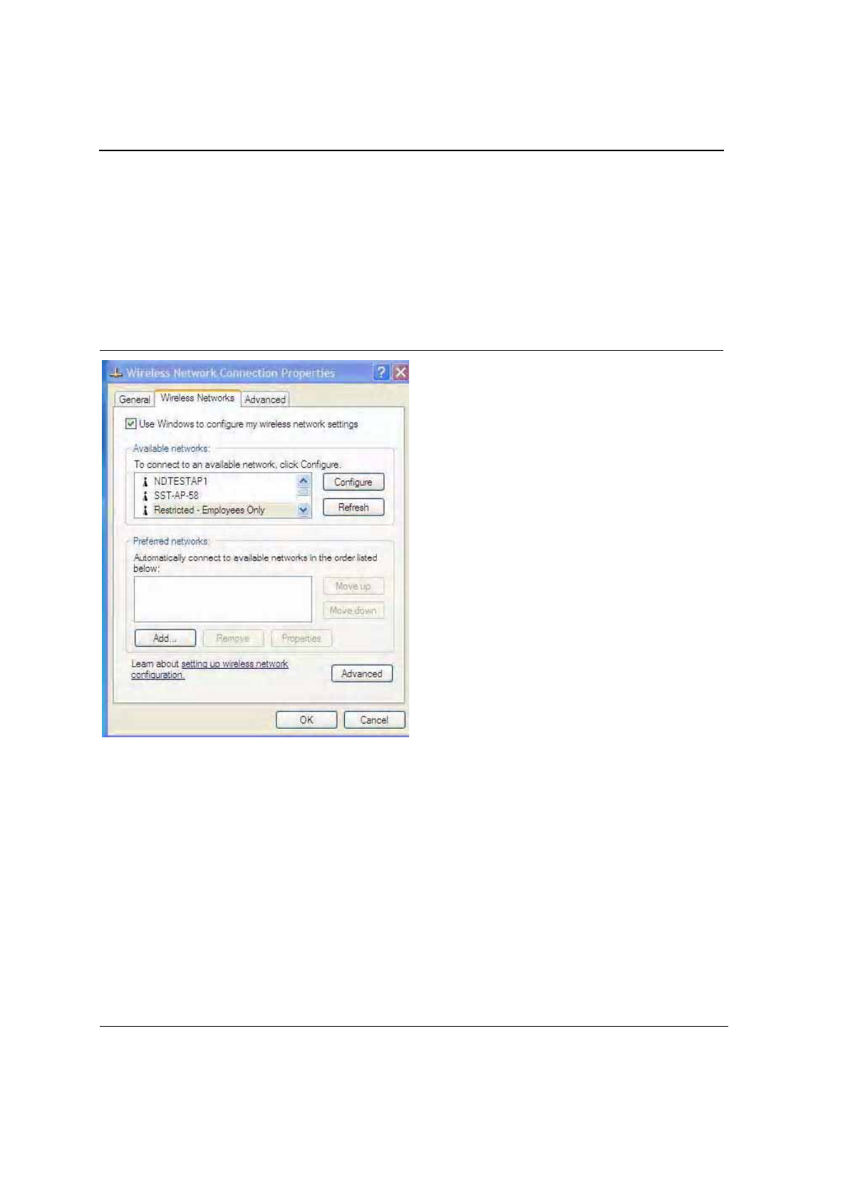
2.2.1 Zero Configuration Utility
To use the Zero Configuration Utility:
1. Open the Control Panel and click on Network Connections.
2. Right click on the icon for the Foxconn client card and select Properties.
3. Click on the Wireless Networks tab.
4. Check the Use Windows to configure my wireless settings checkbox to enable Zero Configuration.
Figure 1: Zero Configuration Utility Window
Configuration Utility Overview
Windows XP Users
Copyright © 2005 Foxconn CONFIDENTIAL Doc. No. MV-S800245-00 Rev. C
May 26, 2005, 2.00 Document Classification: Proprietary Page 13
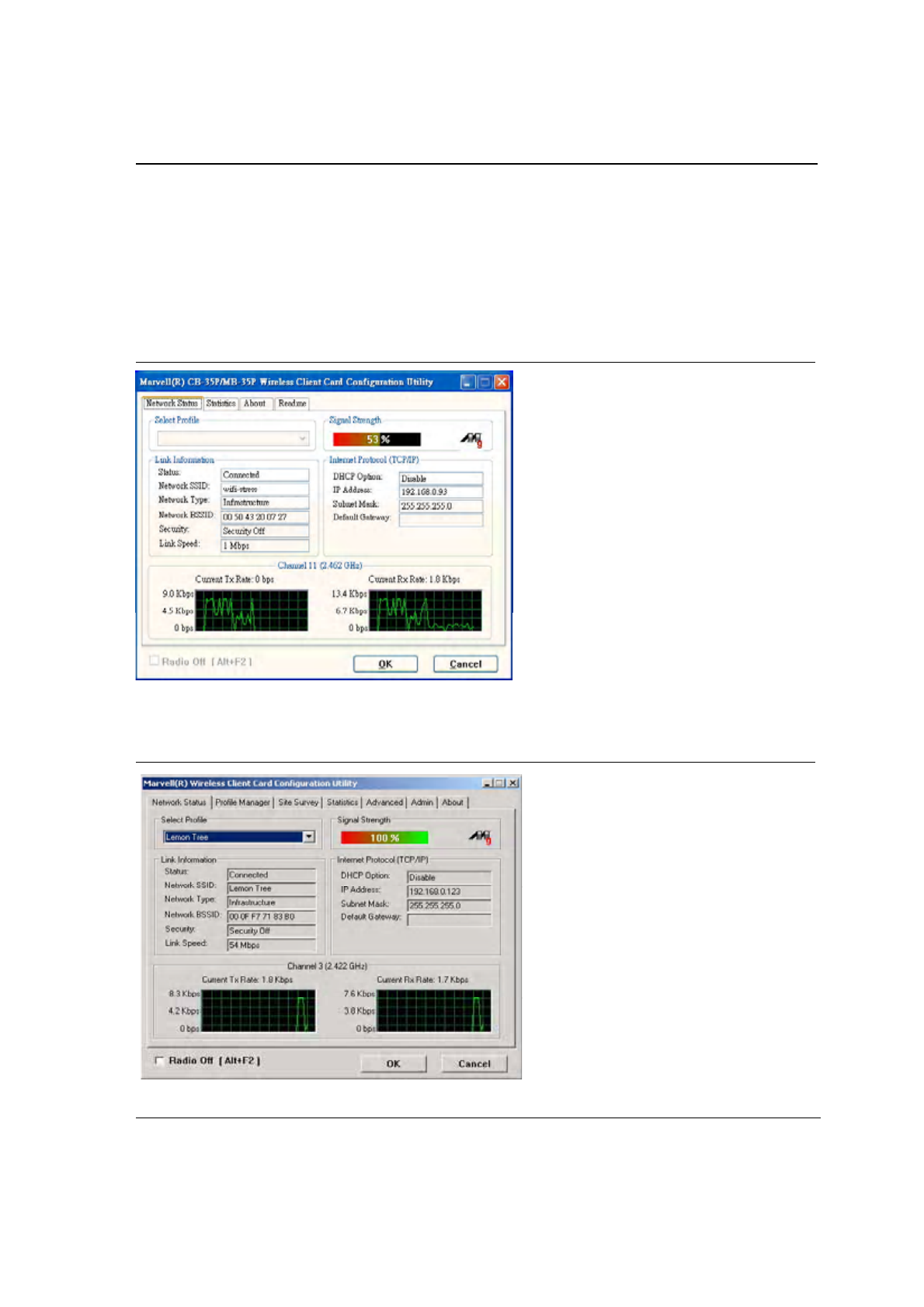
2.2.1.1 Configuration Utility Tabs
When Zero Configuration is enabled, the Foxconn Configuration Utility enters Monitor mode. When in Monitor
mode, the Foxconn Configuration Utility has the following properties:
•
Limited tab display (Network Status,Statistics,About, and Readme tabs)
•
Information reporting only (the Utility cannot be used to configure the card)
Figure 2: Foxconn Configuration Utility in Active Mode
When Zero Configuration is disabled, all tabs available through the Foxconn Configuration Utility are active, as
shown in Figure 2.
Figure 3: Zero Configuration Disabled Window
J20H018
802.11b/g WLAN Module User Guide
Doc. No. MV-S800245-00 Rev. C CONFIDENTIAL Copyright © 2005 Foxconn
Page 14 Document Classification: Proprietary May 26, 2005, 2.00
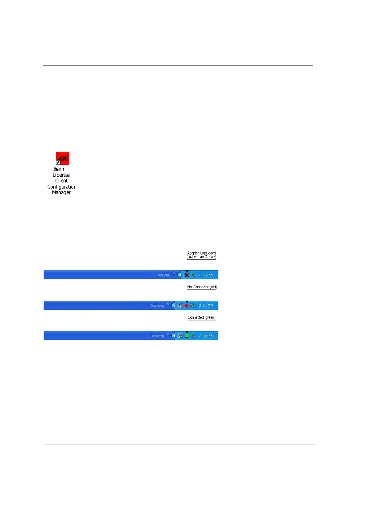
2.2.2 Foxconn Configuration Utility
Once installed, the Foxconn Configuration Utility is accessed from the Start menu or the Desktop:
•
Start > Foxconn Libertas Client Configuration Manager
•
Start > Programs >Foxconn Libertas® 802.11g Client > Foxconn Libertas Client Configuration Manager
•
Desktop—Double click on the Configuration Utility icon
Figure 4: Icon Window
2.2.2.1 Tray Status Icons
Different icons in the system tray indicate the status of the wireless connection:
Figure 5: Tray Status Icons Window

Configuration Utility Overview
Security
Copyright © 2005 Foxconn CONFIDENTIAL Doc. No. MV-S800245-00 Rev. C
May 26, 2005, 2.00 Document Classification: Proprietary Page 15
2.3 Security
Implementing a security infrastructure to monitor physical access to WLAN networks is more difficult than
monitoring access on wired networks. Unlike wired networks where a physical connection is required, anyone
within range of a wireless Access Point can send and receive frames, as well as listen for frames being sent.
IEEE 802.11 defines a set of standards and protocols for use in minimizing the security risks on wireless networks.
Two of these security standards are as follows:
•
802.1x—802.1x authentication provides authenticated access to 802.11 wireless networks and to wired
Ethernet networks. 802.1x minimizes wireless network security risks by providing user and computer
identification, centralized authentication, and encryption services based on the WEP algorithm. 802.1x
supports Extensible Authentication Protocol (EAP). EAP allows the use of different authentication methods,
such as smart cards and certificates.
•
Wi-Fi Protected Access (WPA)—WPA is an implementation based on a subset of the 802.11i standard.
WPA provides enhanced security for wireless networks when used with the TKIP and the Message Integrity
Check (MIC) algorithms.
•
Wi-Fi Protected Access (WPA2)—The next generation of Wi-Fi security, based on the final 802.11i
standard. WPA2 offers the strongest available security in the form of AES-level encryption (Advanced
Encryption Standard), plus faster roaming between access points.
2.3.1 Security Configurations
The configuration utility supports the following security protocols:
•
Authentication Modes
–
Open System
–
Shared Key
–
Auto Switch
–
802.1x
–
WPA-PSK
–
WPA2-PSK
–
WPA
–
WPA2
–
CCX
•
Encryption Methods
–
Security Off
–
WEP
–
TKIP
–
AES
•
802.1x Authentication Protocol
–
EAP/TLS
–
EAP/PEAP
–
EAP/LEAP
•
WEP Key Size
–
64 bits WEP (40-bit key (5 bytes))
–
128 bits WEP (104-bit key (13 bytes))
J20H018
802.11b/g WLAN Module User Guide
Doc. No. MV-S800245-00 Rev. C CONFIDENTIAL Copyright © 2005 Foxconn
Page 16 Document Classification: Proprietary May 26, 2005, 2.00
2.4 AutoLink
AutoLink is a feature integrated in Foxconn wireless client cards that offers users a simple way to configure a new
Foxconn AP in conjunction with the Configuration Utility. The AutoLink dialog box pops up automatically when a
non-configured Foxconn AP or an AutoLink configured Foxconn AP appears in the area of a client card that is not
connected to an AP or Ad-Hoc network.
AutoLink operations include:
•
Configure an AutoLink AP—first time use, AutoLink AP, or renew an AP Configuration
•
Create connection with AutoLink AP—new Foxconn client card connecting to an AutoLink AP
2.4.1 Configure an AutoLink AP
Equipment needed to configure an AutoLink AP:
•
Foxconn AutoLink AP (i.e., AP-32)
•
Foxconn Wireless Client Card (J20H018) and software package (in CD or storage device)
•
Laptop PC or Desktop PC with a Microsoft Windows XP, 2000, ME or 98SE operating system
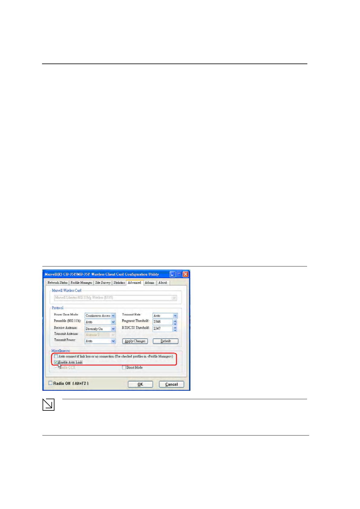
To start or renew an AutoLink AP, configure an AP and create a connection profile for the client card in a secure
wireless network:
1. Install Foxconn Wireless Client Card (J20H018) on PC.
2. Launch Configuration Utility.
3. Click "Advanced" tab.
4. Uncheck "Auto connect …"
5. Check "Enable Auto Link". Click OK button.
Figure 6: AutoLink AP Configuration
Note
Refer to the AP User Guide for the instructions to reset AP configuration to default.
Configuration Utility Overview
AutoLink
Copyright © 2005 Foxconn CONFIDENTIAL Doc. No. MV-S800245-00 Rev. C
May 26, 2005, 2.00 Document Classification: Proprietary Page 17
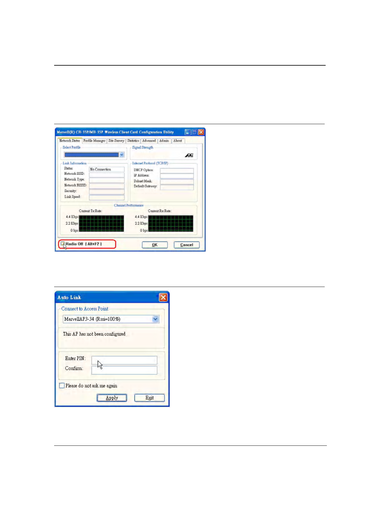
6. Relaunch Configuration Utility.
7. Click “Advanced” tab.
8. Check "Radio Off" below the Miscellaneous box in the utility.
Figure 7: AutoLink AP Configuration—Radio Off
9. Move the Foxconn AP close to the PC and turn the AP power on.
10. An AutoLink dialog box opens immediatetly. If not, click the AP power off and on again.
Figure 8: AutoLink AP Configuration—Security Pin
11. Enter the security PIN number. Click Apply. It takes a few seconds for the AutoLink AP configuration. After
configuration completed, the AutoLink AP restarts automatically.
J20H018
802.11b/g WLAN Module User Guide
Doc. No. MV-S800245-00 Rev. C CONFIDENTIAL Copyright © 2005 Foxconn
Page 18 Document Classification: Proprietary May 26, 2005, 2.00
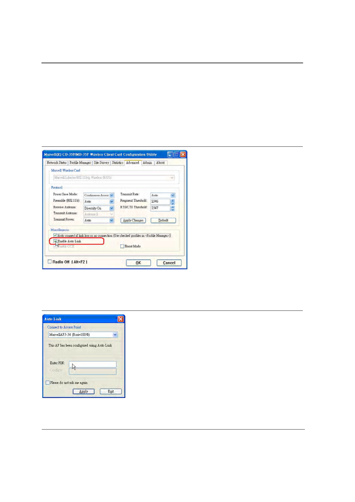
2.4.2 Create Connection with AutoLink AP
To set up a Foxconn wireless client card connection to an existing Foxconn AutoLink AP:
1. Install Foxconn Wireless Adapter (j20H018) on PC. Open device driver and Configuration Utility installation.
2. Launch Configuration Utility.
3. Click "Advanced" tab.
4. Check "Enable Auto Link" and click OK button.
Figure 9: AutoLink AP Connection
5. An AutoLink dialog box opens immediatetly. If not, make sure the "Radio Off" button below the Miscellaneous
box in the utility is unchecked.
6. Select the AP in which to connect, and enter the PIN number used in this AutoLink AP. Click Apply.
Figure 10: AutoLink AP Connection—Security Pin

Configuration Utility User Interface
Copyright © 2005 Foxconn CONFIDENTIAL Doc. No. MV-S800245-00 Rev. C
May 26, 2005, 2.00 Document Classification: Proprietary Page 19
Section 3. Configuration Utility User Interface
The Configuration Utility allows configuration of Foxconn client cards through the following tabs:
•
Network Status Tab—displays the status of the network to which the user is connected. The Configuration
Utility initializes on this page
•
Profile Manager Tab—displays the current profiles and allows the user to set attributes for network type,
security options, and protocols, as well as create/modify/delete profiles
•
Site Survey Tab—displays site survey information
•
Statistics Tab—displays the statistics of the current session
•
Advanced Tab—used to set protocol parameters
•
Admin Tab—used to import and export profiles
•
About Tab—provides the information for the driver version number, firmware version number, Config Utility
version number, and MAC address of the client card etc.
J20H018
802.11b/g WLAN Module User Guide
Doc. No. MV-S800245-00 Rev. C CONFIDENTIAL Copyright © 2005 Foxconn
Page 20 Document Classification: Proprietary May 26, 2005, 2.00
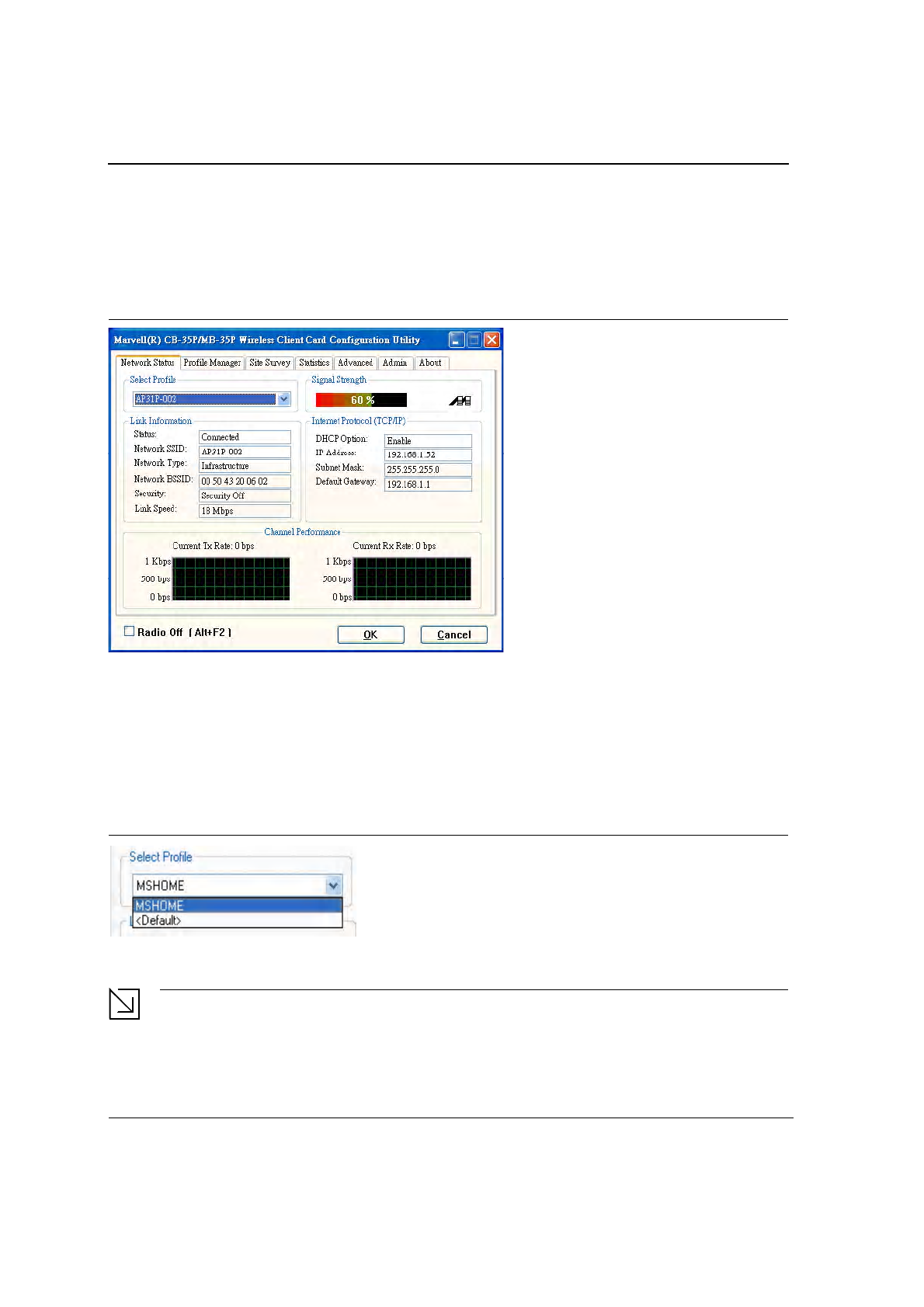
3.1 Network Status Tab
The Network Status tab displays the status of the network. When the Wireless Client Card Configuration
Utility initializes, it displays the Network Status tab:
Figure 11: Network Status Window
3.1.1 Select Profile
The Select Profile window displays the name of the profile in use. Additional information about the profile is
provided in the Profile Manager.
Select one of the profiles previously defined by clicking the down arrow and highlighting a profile from the
pulldown list.
Figure 12: Select Profile Window
Profiles are created, modified, and deleted through the Profile Manager.
Note
This feature is disabled when Zero Configuration is enabled.
Configuration Utility User Interface
Network Status Tab
Copyright © 2005 Foxconn CONFIDENTIAL Doc. No. MV-S800245-00 Rev. C
May 26, 2005, 2.00 Document Classification: Proprietary Page 21
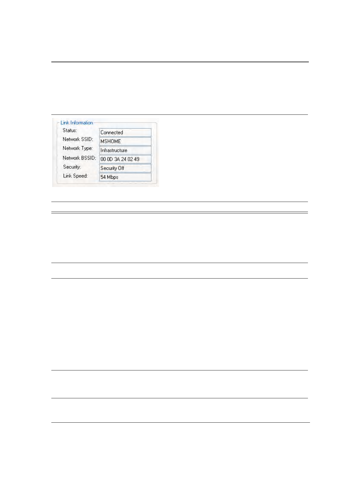
3.1.2 Link Information
The Link Information section contains the current information about the wireless connection:
Figure 13: Link Information Section
Table 1: Link Information Window Description
Fields Description
Status Status of the wireless network connection:
•
Card Unplugged—adapter is not plugged in, or adapter is plugged in but
not recognized.
•
Connected—card plugged in and connected to a wireless network
•
Not connected—card plugged in, but no wireless connection.
•
No Radio—card plugged in, but the radio is turned off. Uncheck the
Radio Off box to turn the radio on.
Network SSID Network SSID label (i.e., Network Name). The Network Name is a text string
of up to 32 characters.
Network Type Type of environment connected to:
•
Infrastructure Mode—wireless clients send and receive information
through the APs. When a wireless client communicates with another, it
transmits to the AP. First the AP receives the information and
rebroadcasts it, then other devices receive the information. The APs are
strategically located within an area to provide optimal coverage for
wireless clients. A large WLAN uses multiple APs to provide coverage
over a wide area. APs can connect to a LAN through a wired Ethernet
connection. APs send and receive information from the LAN through the
wired connection.
•
Ad-Hoc Mode—wireless clients send and receive information to other
wireless clients without using an AP. This type of WLAN only contains
wireless clients. Use Ad-Hoc mode to network computers at home or in
small office, or to set up a temporary wireless network for a meeting.
Network BSSID Network Basic Service Set Identifier. The BSSID is a 48-bit identity used to
identify a particular BSS within an area. In Infrastructure BSS networks, the
BSSID is the MAC address of the AP. In independent BSS or Ad-Hoc
networks, the BSSID is generated randomly.
J20H018
802.11b/g WLAN Module User Guide
Doc. No. MV-S800245-00 Rev. C CONFIDENTIAL Copyright © 2005 Foxconn
Page 22 Document Classification: Proprietary May 26, 2005, 2.00
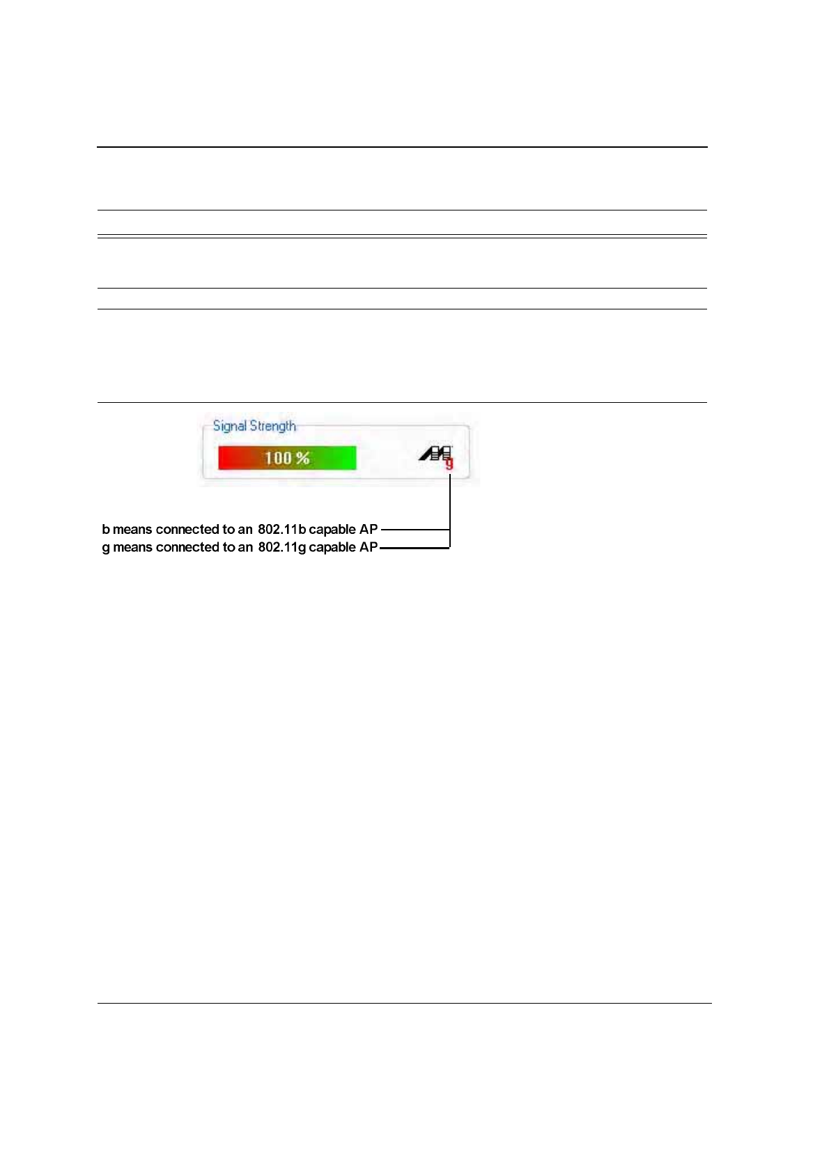
3.1.3 Signal Strength/Wireless Mode Indicator
The color-coded Signal Strength bar displays the signal strength of the last packet received by the adapter:
Figure 14: Signal Strength Bar Window
Signal strength is reported as a percentage. A signal in the red indicates a bad connection. A signal in the green
indicates a good connection.
The Wireless Mode indicator shows the data rates the client card operates. There are two modes:
•
802.11b
•
802.11g (backward compatible to 802.11b)
Security Reports the type and level of security set. The security level is set through the
Profile Setting of the Profile Manager tab. Configure security settings also
through the Site Survey tab when connecting to a network.
Link Speed Connection speed, (i.e., 54 Mbps, 48 Mbps, etc.)
Table 1: Link Information Window Description
Fields Description
Configuration Utility User Interface
Network Status Tab
Copyright © 2005 Foxconn CONFIDENTIAL Doc. No. MV-S800245-00 Rev. C
May 26, 2005, 2.00 Document Classification: Proprietary Page 23
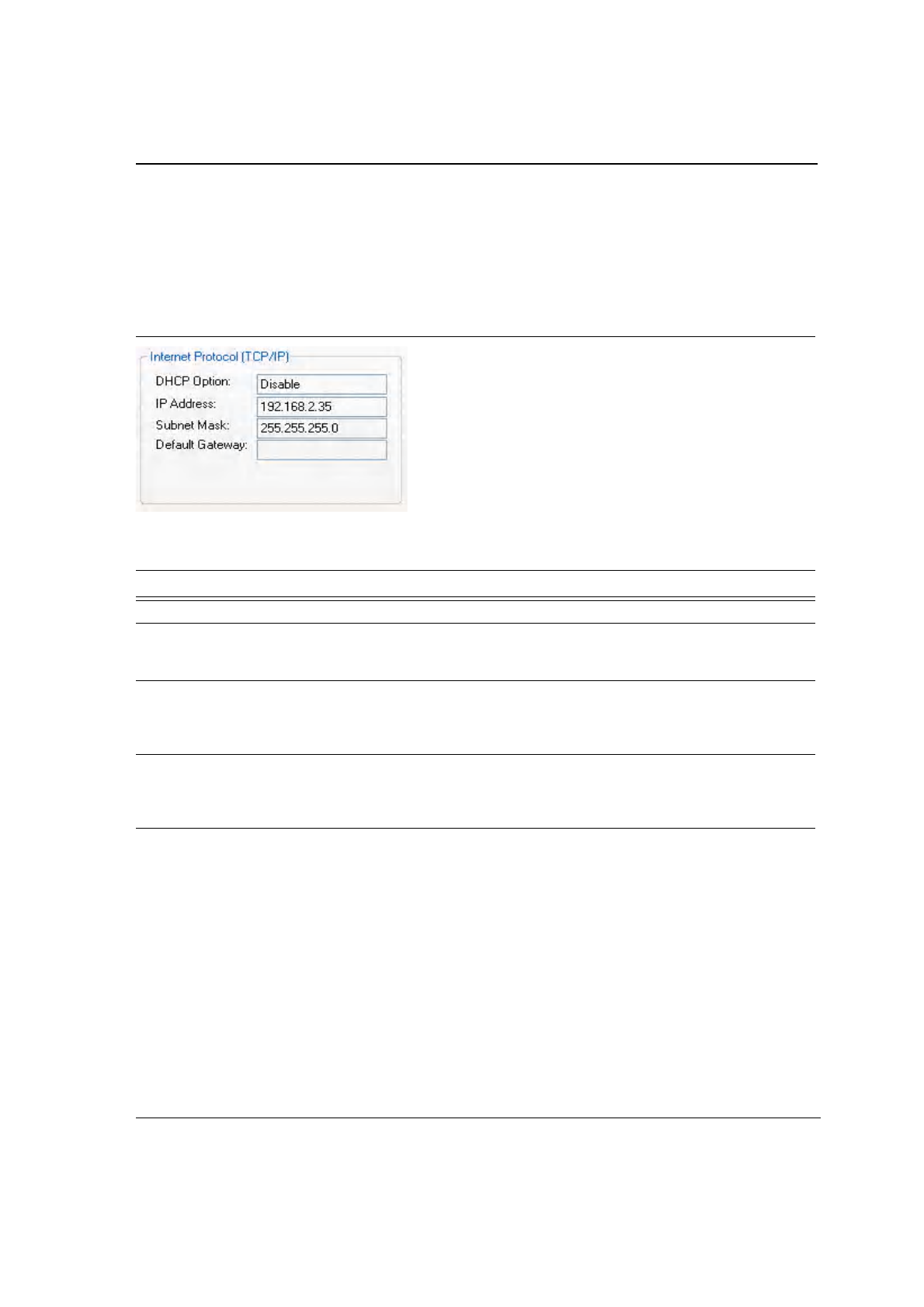
3.1.4 Internet Protocol (TCP/IP)
The Internet Protocol specifies the format of packets, also called datagrams, and the addressing scheme. Most
networks combine IP with a higher-level protocol called TCP, which establishes a virtual connection between a
destination and a source.
Figure 15: TCP/IP Window
The parameters of the Internet Protocol are:
Table 2: TCP/IP Window Description
Field Description
DHCP Option Dynamic Host Configuration Protocol. Either enabled or disabled
IP Address An identifier for a computer or device on a TCP/IP network. The format of an
IP address is a 32-bit numeric address written as four numbers separated by
periods. Each number can be 0 to 255.
Subnet Mask A mask used to determine what subnet an IP address belongs to. An IP
address has two components, the network address and the host address. The
first two numbers represent the Class B network address, and the second two
numbers identify a particular host on this network.
Default Gateway The default node on a network that serves as an entrance to another network.
In enterprises, the gateway is the computer that routes the traffic from a
workstation to the outside network that is serving the Web pages. In homes,
the gateway is the ISP that connects the user to the internet.
J20H018
802.11b/g WLAN Module User Guide
Doc. No. MV-S800245-00 Rev. C CONFIDENTIAL Copyright © 2005 Foxconn
Page 24 Document Classification: Proprietary May 26, 2005, 2.00
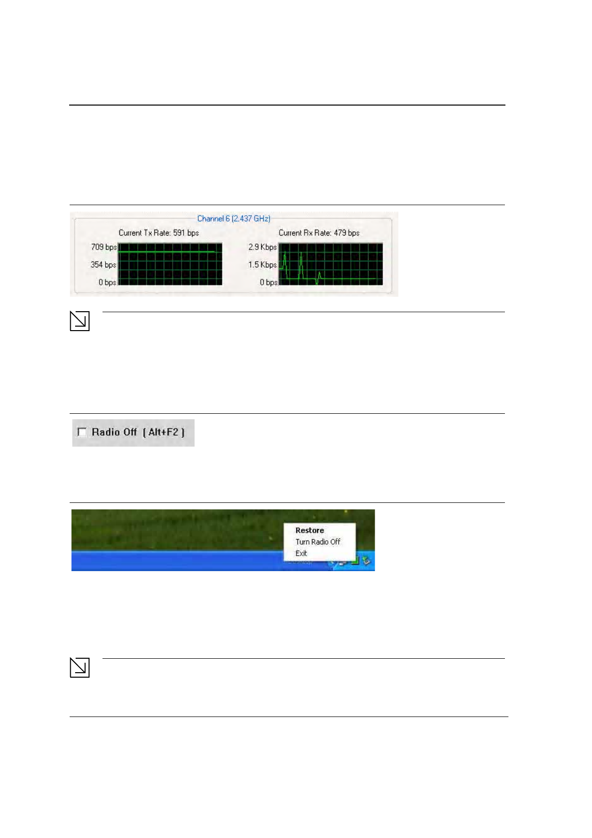
3.1.5 Actual Throughput Performance
This section of the Network Status tab displays the Current Tx Rate and the Current Rx Rate of the channel
being monitored.
Figure 16: Actual Throughput Performance Window
Note
These are actual throughput diagrams (without the WLAN overhead delivered by the client card).
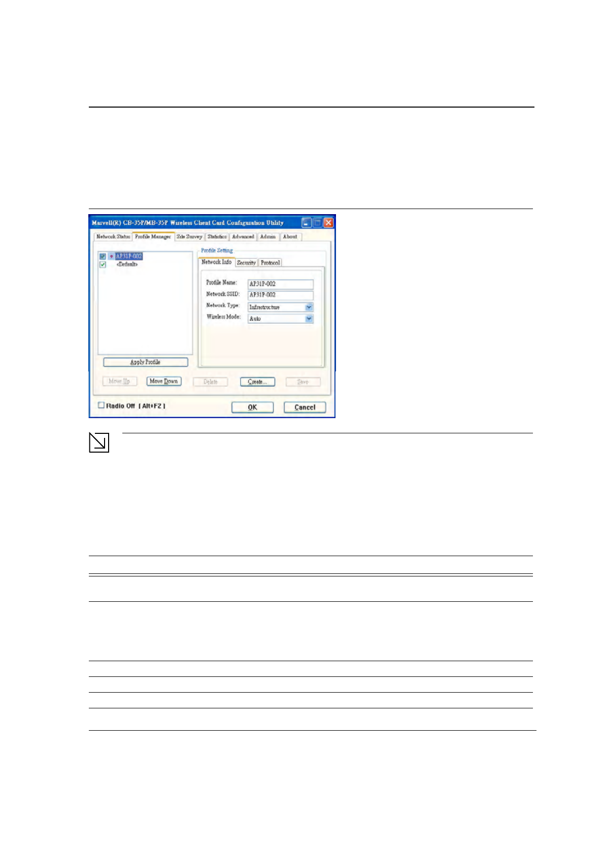
3.1.6 Radio On/Off Box
Clicking the Radio Off check box turns off the radio. Unchecking the box turns on the radio.
Figure 17: Radio On/Off Window
Another way to turn the radio on or off is to right-click the Configuration Utility icon in the System Tray and click
Turn Radio Off to turn the radio off. When the radio is off, click Turn Radio On to turn the radio back on.
Figure 18: Radio Off Window
The system hot key (Alt+F2) is also used to turn the radio on/off.
When the radio is off, there is no radio activity, and the following property pages are disabled:
•
Site Survey
•
Statistics
•
Advanced
Note
This feature is disabled when Zero Configuration is enabled.
Configuration Utility User Interface
Profile Manager Tab
Copyright © 2005 Foxconn CONFIDENTIAL Doc. No. MV-S800245-00 Rev. C
May 26, 2005, 2.00 Document Classification: Proprietary Page 25
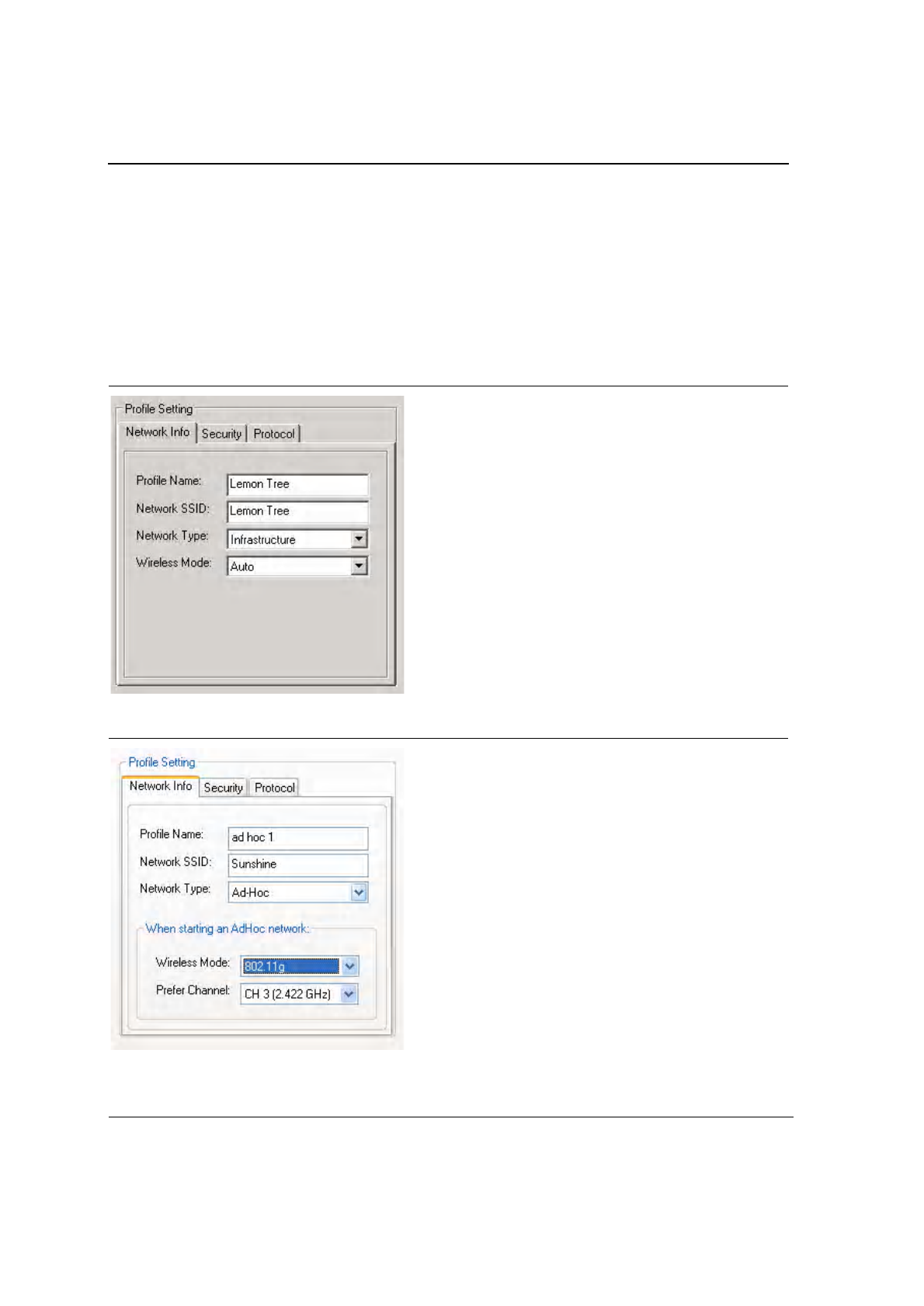
3.2 Profile Manager Tab
Clicking on the Profile Manager tab displays the Profile Manager dialog box. The Profile Manager displays the
profiles available and allows you to create, modify, and delete profiles:
Figure 19: Profile Manager Window
Note
The Profile Manager window is not accessible when Zero Configuration is enabled.
PROFILE MANAGER—PROFILE LIST WINDOW
The window on the left side of this tab lists all of the profiles available. Highlighting a profile selects it. If the Default
box next to the profile is checked, that profile is used in auto-configuration mode when the link is lost. If it is
unchecked, that profile is excluded in auto-configuration. The controls associated with this window are:
Table 3: Profile List Window Description
Fields Description
Apply Profile Applies the profile selected or user call
Apply the profile by double-clicking on the desired profile.
Move Up / Move Down Moves the profile up and down in the window
All profiles with the Network Type set to Infrastructure are displayed before the
profiles with the Network Type set to Ad-Hoc. In auto-configuration mode, the
checked priorities at the top of the list have higher priority than checked
profiles at the bottom of the list.
Delete Deletes a profile
Create Creates a profile
Save Saves changes made to a selected profile
J20H018
802.11b/g WLAN Module User Guide
Doc. No. MV-S800245-00 Rev. C CONFIDENTIAL Copyright © 2005 Foxconn
Page 26 Document Classification: Proprietary May 26, 2005, 2.00
PROFILE MANAGER—PROFILE SETTING
The Profile Settings are used to display information about the profile selected in the Profile List window. The
information is divided into three tabs: Network Info, Security, and Protocol.
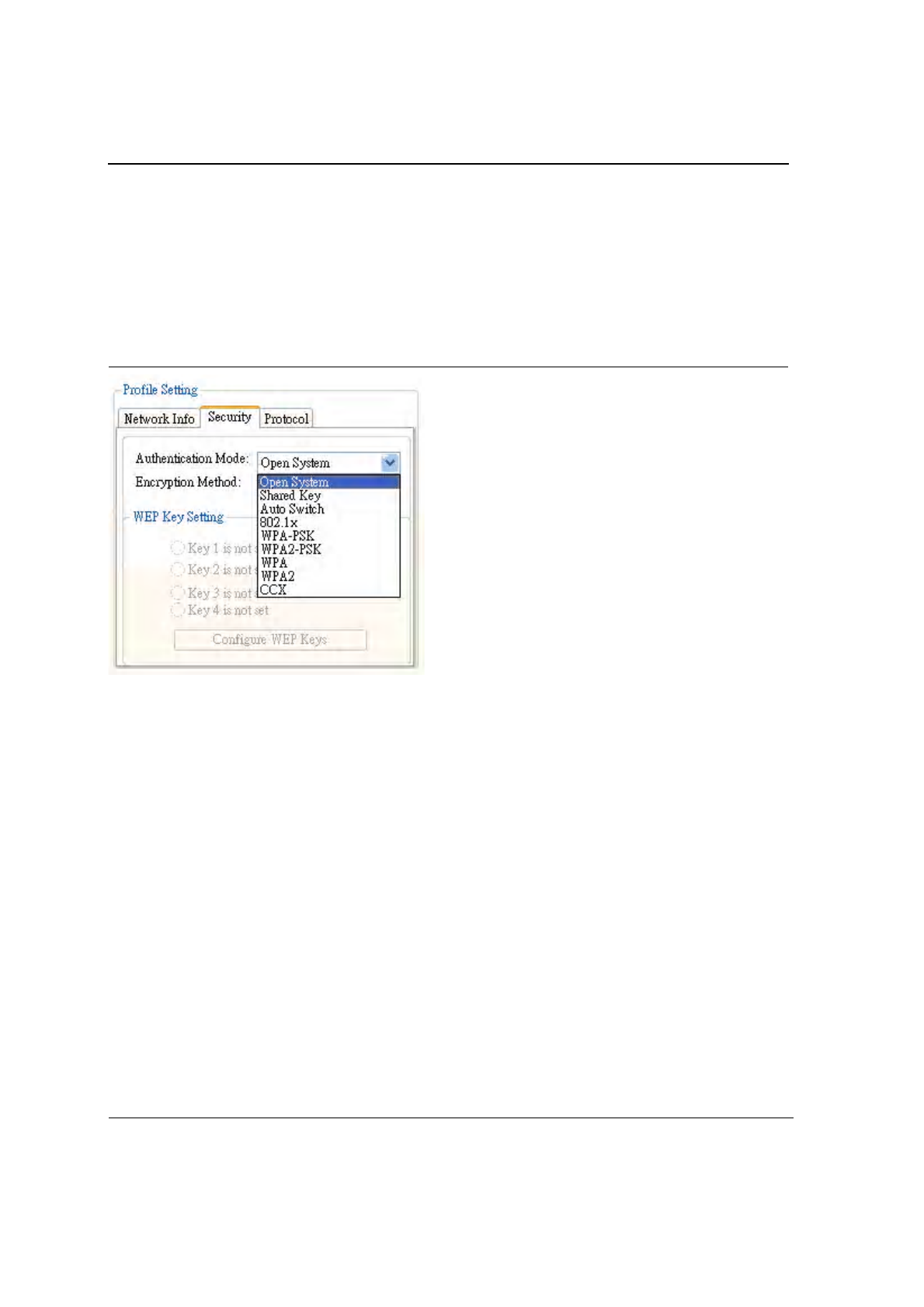
3.2.1 Profile Setting—Network Info Tab
The Profile Manager initially displays the Network Info tab. The Network Info tab displays the following fields:
Figure 20: Network Info Tab—Infrastructure Network
Figure 21: Network Info Tab—Ad-Hoc Network

Configuration Utility User Interface
Profile Manager Tab
Copyright © 2005 Foxconn CONFIDENTIAL Doc. No. MV-S800245-00 Rev. C
May 26, 2005, 2.00 Document Classification: Proprietary Page 27
Note
Prefer Channel and Wireless Mode are used only when an Ad-Hoc network is started by the client card.
These two attributes are ignored if the client card is connected to an existing Ad-Hoc network with the
same desired SSID.
Table 4: Network Info Description
Fields Description
Profile Name Profile name
Network SSID Network SSID label
Network Type Infrastructure: When an Infrastructure network is selected, the Profile Setting
displays the Wireless Mode field.
Ad-Hoc: When an Ad-Hoc network is selected, the Profile Setting displays an
additional Prefer Channel field.
Wireless Mode Auto: Connects to either 802.11g network or 802.11b network (Infrastructure
network only).
802.11g: Connects to either 802.11g or 802.11b network (Ad-Hoc network
only).
802.11b: Connects to 802.11b network only (Available in both Infrastructure
and Ad-Hoc networks).
Prefer Channel Channel being used (Ad-Hoc network only)
J20H018
802.11b/g WLAN Module User Guide
Doc. No. MV-S800245-00 Rev. C CONFIDENTIAL Copyright © 2005 Foxconn
Page 28 Document Classification: Proprietary May 26, 2005, 2.00
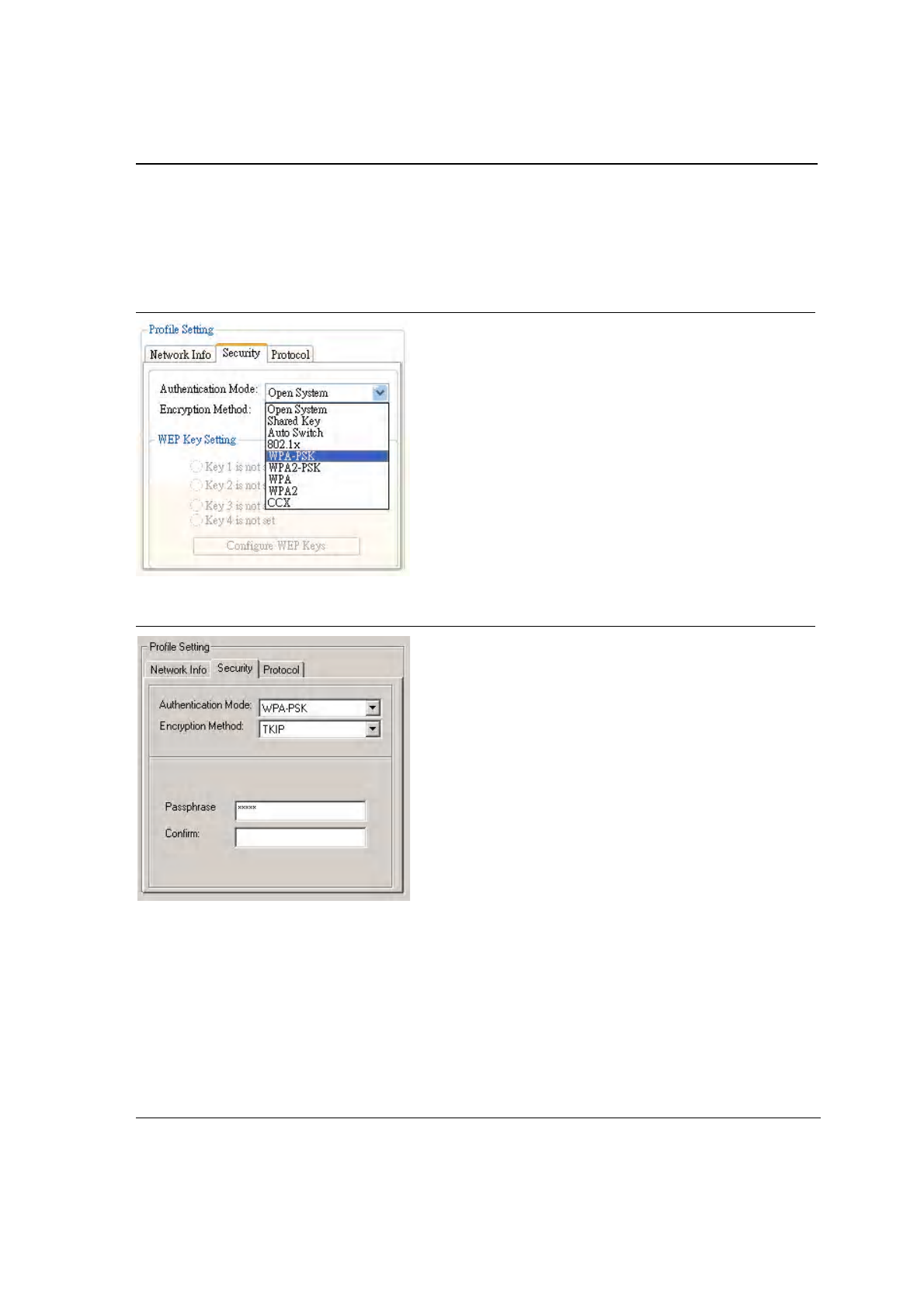
3.2.2 Profile Setting—Security Tab
Clicking on the Security tab displays the following security options:
•
Authentication Mode
•
Encryption Method (Security off, WEP, TKIP, and AES)
•
WEP Key Setting (Passphrase Key or Authentication Protocol)
Figure 22: Authentication Modes
3.2.2.1 Non-WPA Authentication Modes
The Foxconn Configuration Utility currently supports the following non-WPA authentication modes:
•
Open System—Open Authentication (no key or a pre-shared wired equivalent privacy (WEP) key is required)
•
Shared Key—Shared Authentication (a pre-shared wired equivalent privacy (WEP) key is required)
•
Auto Switch—Auto Select Authentication modes (Open System or Shared Key, WEP key required)
3.2.2.2 WPA Authentication Modes
The Foxconn Configuration Utility currently supports the following WPA Authentication Modes:
•
802.1x (TLS/PEAP)
•
WPA-PSK
•
WPA2-PSK
•
WPA (TLS/PEAP/LEAP)
•
WPA2 (TLS/PEAP/LEAP)
•
CCX (LEAP)
Configuration Utility User Interface
Profile Manager Tab
Copyright © 2005 Foxconn CONFIDENTIAL Doc. No. MV-S800245-00 Rev. C
May 26, 2005, 2.00 Document Classification: Proprietary Page 29
3.2.2.2.1 WPA-PSK/WPA2-PSK Support
In Infrastructure Mode, if WPA-PSK/WPA2-PSK is selected as the Authentication Mode, either TKIP or AES is
selected as the Encryption Method.
Figure 23: WPA-PSK/WPA2-PSK Authentication
Figure 24: WPA-PSK/WPA2-PSK with TKIP
•
Enter the network passphrase in the “Passphrase” and “Confirm” fields.
•
WPA-PSK/WPA2-PSK is not supported in Ad-Hoc network mode.
3.2.2.2.2 802.1x/WPA/WPA2 EAP-TLS Support
If 802.1x/WPA/WPA2 is selected, AES or TKIP encryption is available, and a certificate is required for the
authentication.
1. To connect to an AP through the Radius Server, select 802.1x/WPA/WPA2 as the Authentication Mode.
2. Select WEP, TKIP, or AES as the Encryption Method.
3. Select EAP/TLS (Use Certificate) as the 802.1x Authentication Protocol.
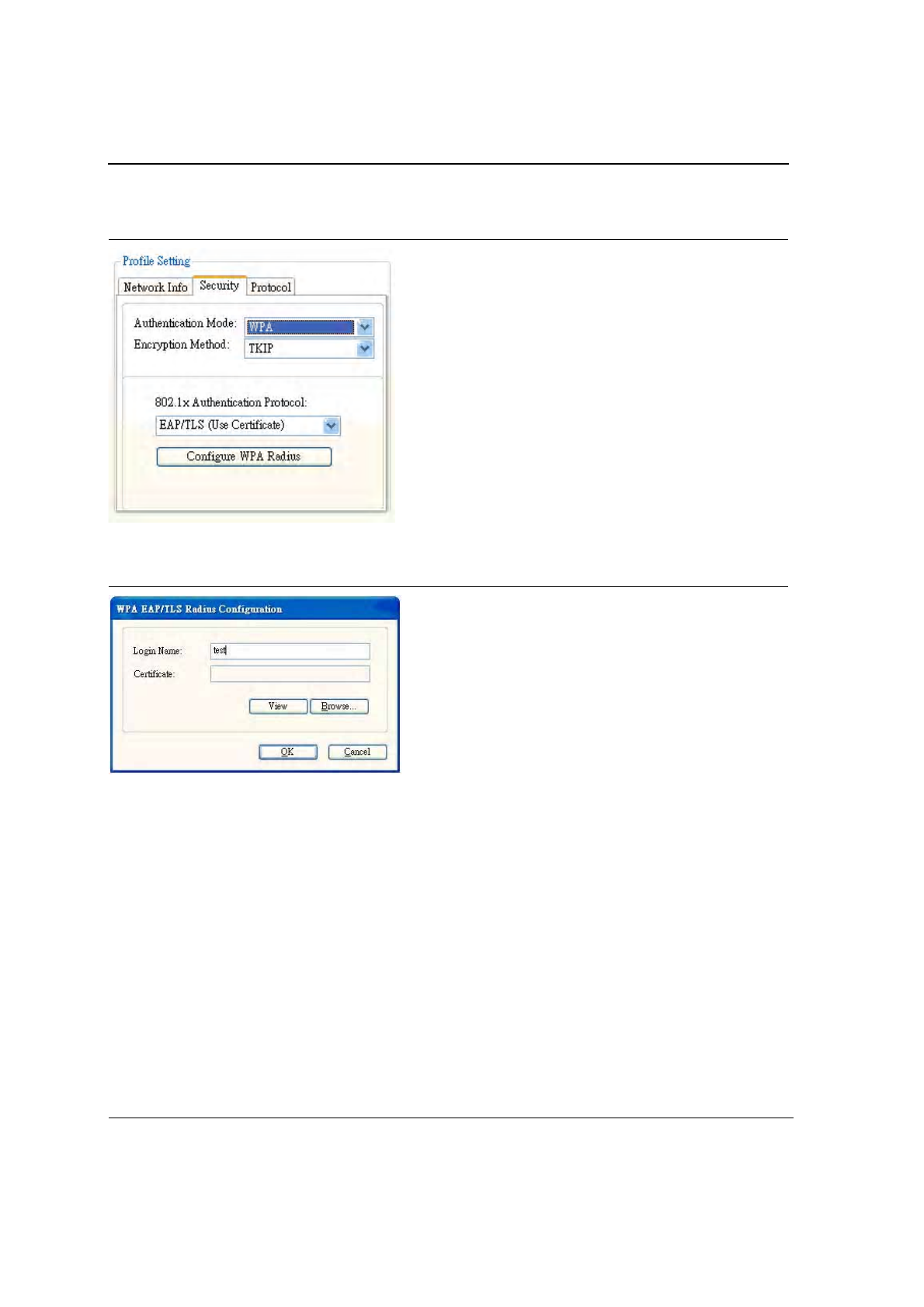
J20H018
802.11b/g WLAN Module User Guide
Doc. No. MV-S800245-00 Rev. C CONFIDENTIAL Copyright © 2005 Foxconn
Page 30 Document Classification: Proprietary May 26, 2005, 2.00
Figure 25: 802.1x/WPA/WPA2 EAP-TLS Authentication
4. Click the Configure WPA Radius button to configure security settings.
Figure 26: 802.1x/WPA/WPA2 EAP-TLS Radius Configuration
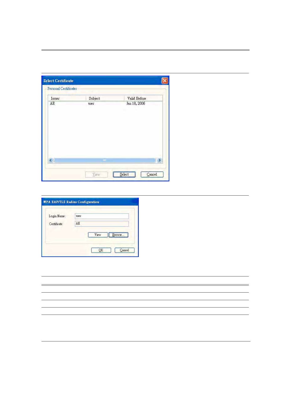
5. Click the Browse button to activate the dialog for selecting a certificate.
6. Before clicking the OK button to exit the dialog, make sure that the Login Name is entered.
Configuration Utility User Interface
Profile Manager Tab
Copyright © 2005 Foxconn CONFIDENTIAL Doc. No. MV-S800245-00 Rev. C
May 26, 2005, 2.00 Document Classification: Proprietary Page 31
Figure 27: Select Certificate Window
Figure 28: WPA Radius Configuration with Certificate
Table 5: 802.1x/WPA/WPA2 EAP-TLS Radius Configuration
Fields Description
Login Name Login name to the RADIUS server
Certificate Certificate selected for authentication
View View button to view the selected certificate
Browse Browse button to select the certificate
J20H018
802.11b/g WLAN Module User Guide
Doc. No. MV-S800245-00 Rev. C CONFIDENTIAL Copyright © 2005 Foxconn
Page 32 Document Classification: Proprietary May 26, 2005, 2.00
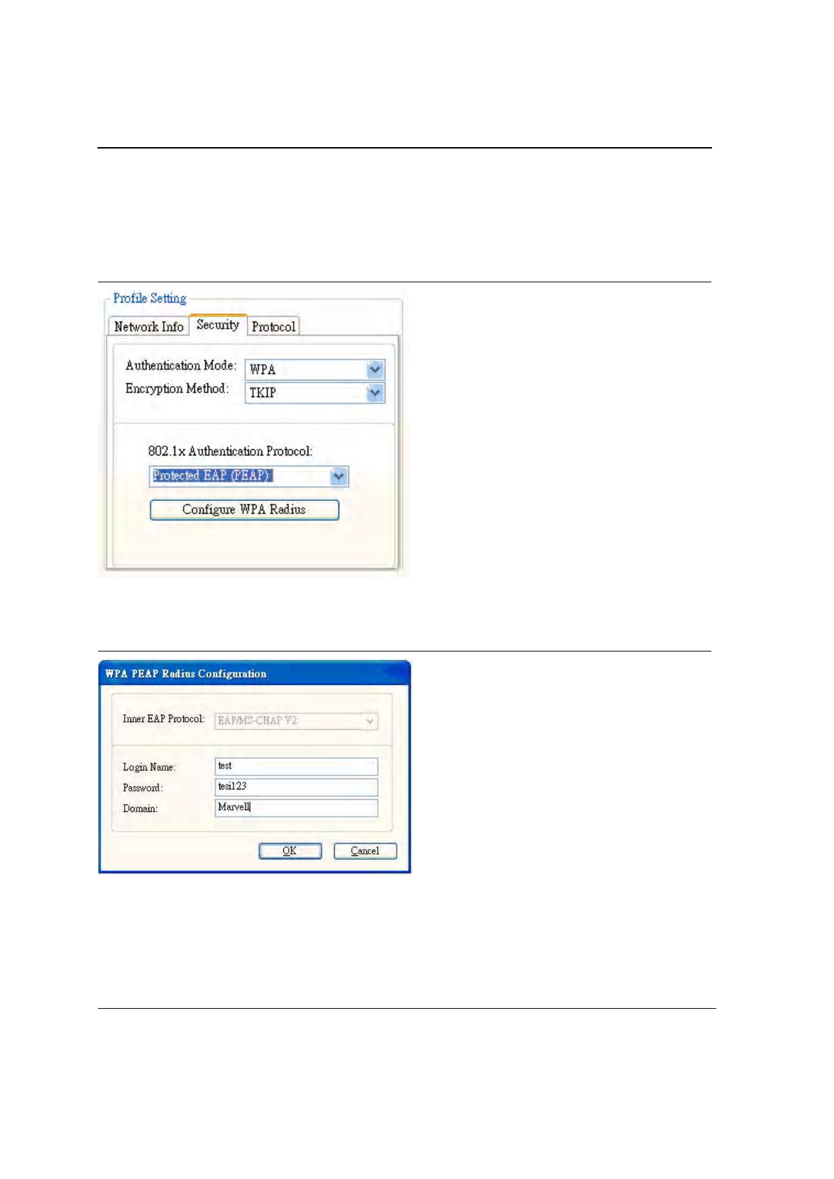
3.2.2.2.3 802.1x/WPA/WPA2 PEAP Support in Infrastructure Mode
To connect to an AP through the Radius Server, select 802.1x/WPA/WPA2 as the Authentication Mode, Protected
EAP (PEAP) as the Authentication Protocol, and AES or TKIP as the Encryption Method.
Figure 29: 802.1x/WPA/WPA2 PEAP Authentication
Clicking on the Configure WPA Radius button displays the WPA PEAP Radius Configuration window. Enter all of
the required information. Click OK button to set the configuration.
Figure 30: 802.1x/WPA/WPA2 PEAP Radius Configuration

Configuration Utility User Interface
Profile Manager Tab
Copyright © 2005 Foxconn CONFIDENTIAL Doc. No. MV-S800245-00 Rev. C
May 26, 2005, 2.00 Document Classification: Proprietary Page 33
Table 6: WPA PEAP Radius Configuration
Fields Description
Inner EAP Protocol Currently supports EAP/MS-CHAP V2 only
Login Name Login name to the RADIUS server
Password Password to login to the RADIUS server
Domain Domain name for login to the RADIUS server (optional)
J20H018
802.11b/g WLAN Module User Guide
Doc. No. MV-S800245-00 Rev. C CONFIDENTIAL Copyright © 2005 Foxconn
Page 34 Document Classification: Proprietary May 26, 2005, 2.00
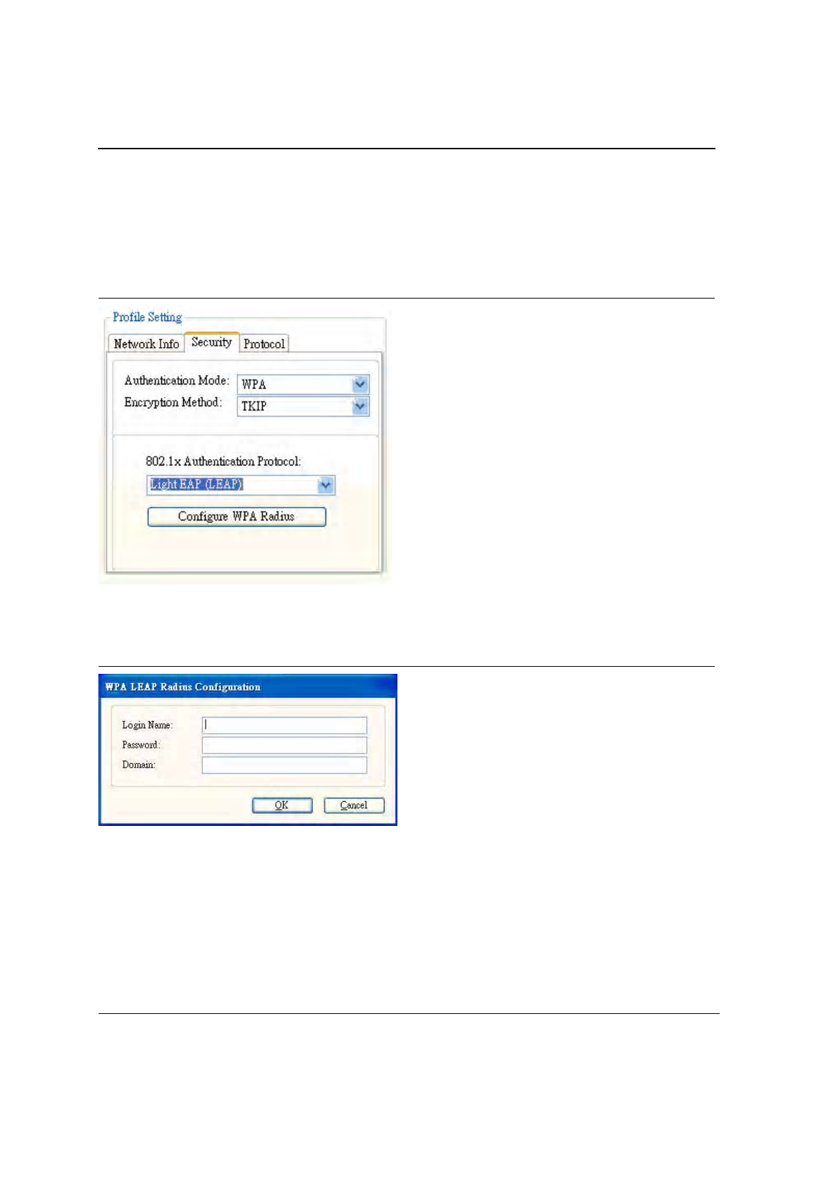
3.2.2.2.4 WPA/WPA2 EAP/LEAP
To connect to an AP through the Radius Server, select WPA/WPA2 as the Authentication Mode, Light EAP (LEAP)
as the 802.1x Authentication Protocol, and TKIP as the Encryption Method for WPA LEAP or AES as the
Encryption Method for WPA2 LEAP.
Figure 31: WPA/WPA2 EAP/LEAP Authentication
Clicking on the Configure WPA Radius button configures the security settings displays the WPA LEAP Radius
Configuration Window. Enter all the required information. Click OK button to set the configuration.
Figure 32: WPA/WPA2 EAP/LEAP Radius Configuration
Configuration Utility User Interface
Profile Manager Tab
Copyright © 2005 Foxconn CONFIDENTIAL Doc. No. MV-S800245-00 Rev. C
May 26, 2005, 2.00 Document Classification: Proprietary Page 35
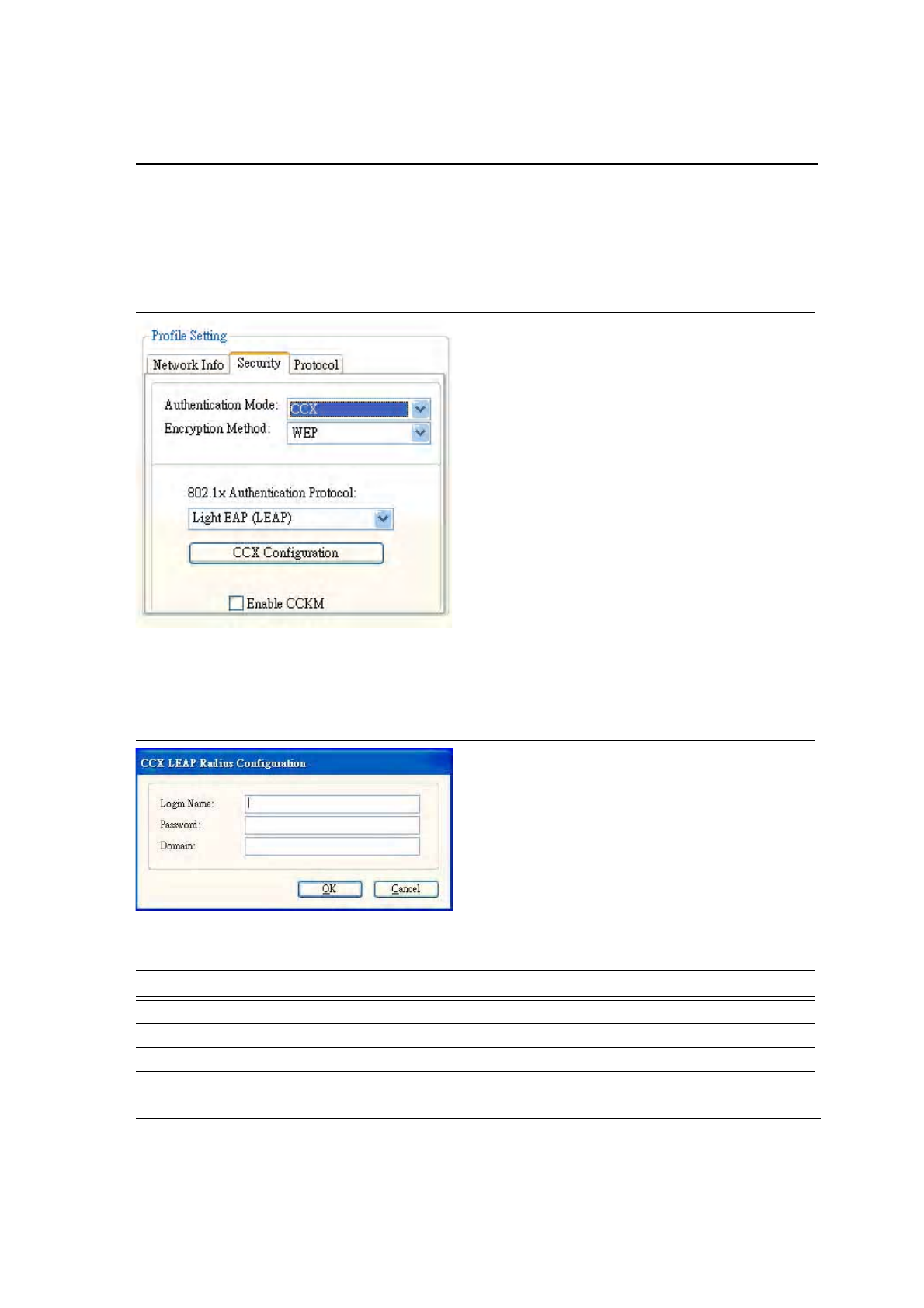
3.2.2.2.5 CCX EAP/LEAP
To connect to a Cisco
®
AP through the Radius Server, select CCX EAP/LEAP. WEP is the encryption method and
the key is generated automatically.
Figure 33: CCX EAP/LEAP Authentication
If Enable CCKM is checked, the Cisco Centrailized Key Management (CCKM) is enabled.
Clicking on the CCX Configuration button displays the CCX LEAP Radius Configuration window. Enter all the
required information in CCX configuration box. Click OK button to set CCX EAP/LEAP configuration.
Figure 34: CCX EAP/LEAP Radius Configuration
Table 7: CCX EAP/LEAP Radius Configuration
Fields Description
Login Name Login name to the RADIUS server.
Password Password to login to the RADIUS server.
Domain Domain name to login to the RADIUS server (optional).
J20H018
802.11b/g WLAN Module User Guide
Doc. No. MV-S800245-00 Rev. C CONFIDENTIAL Copyright © 2005 Foxconn
Page 36 Document Classification: Proprietary May 26, 2005, 2.00
3.2.2.3 Encryption Methods
The following encryption methods are available, depending on the Authentication Mode:
•
Security Off
•
WEP
•
TKIP
•
AES
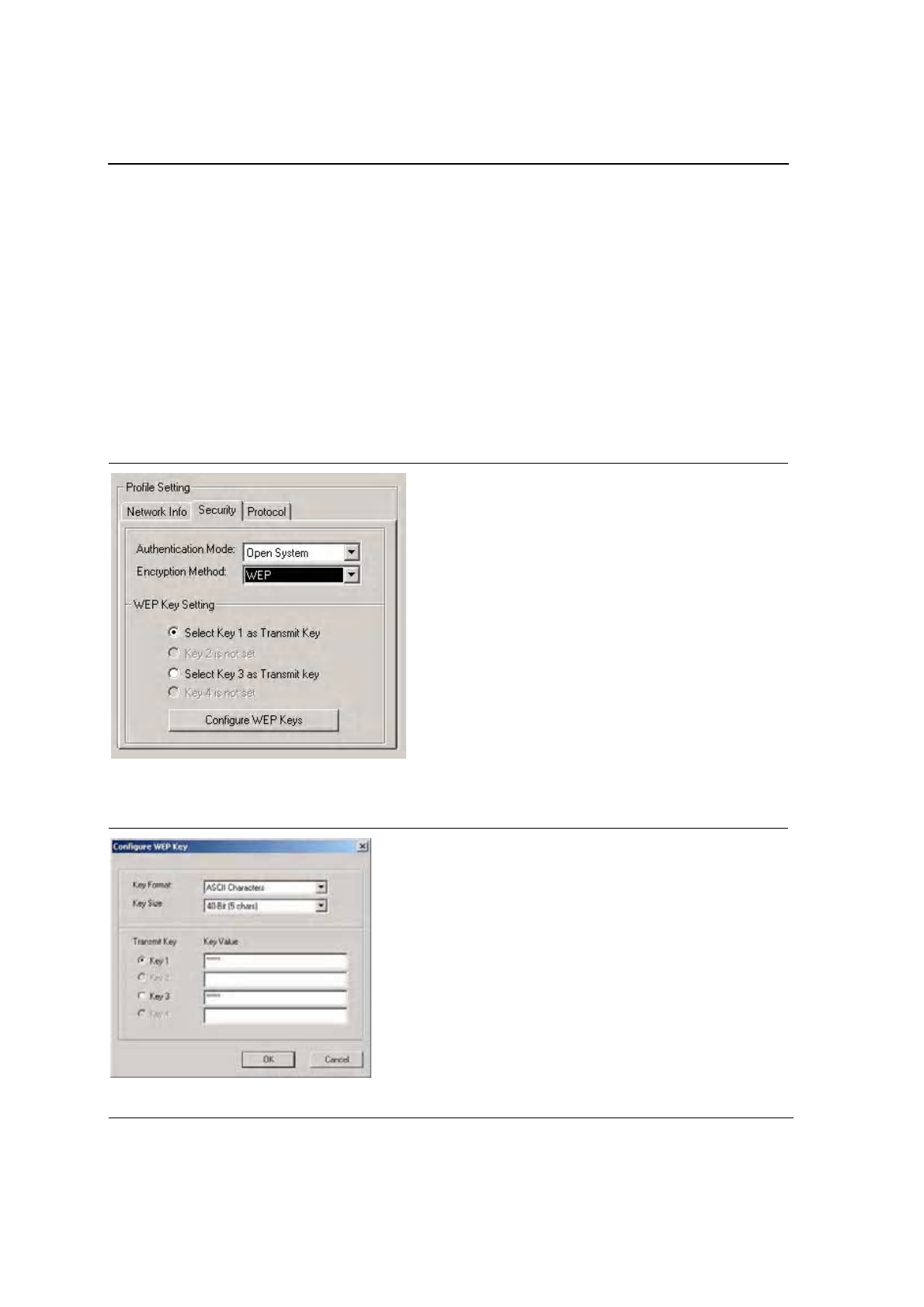
3.2.2.4 WEP Key Settings
If the WEP Encryption method is selected, the security tab displays the WEP Key Setting. To configure the WEP
keys, select any WEP Key Setting and press the Configure WEP Keys button.
Figure 35: WEP Key Settings
Clicking the Configure WEP Keys button displays the Configure WEP Key dialog box:
Figure 36: WEP Key Configuration
Configuration Utility User Interface
Profile Manager Tab
Copyright © 2005 Foxconn CONFIDENTIAL Doc. No. MV-S800245-00 Rev. C
May 26, 2005, 2.00 Document Classification: Proprietary Page 37
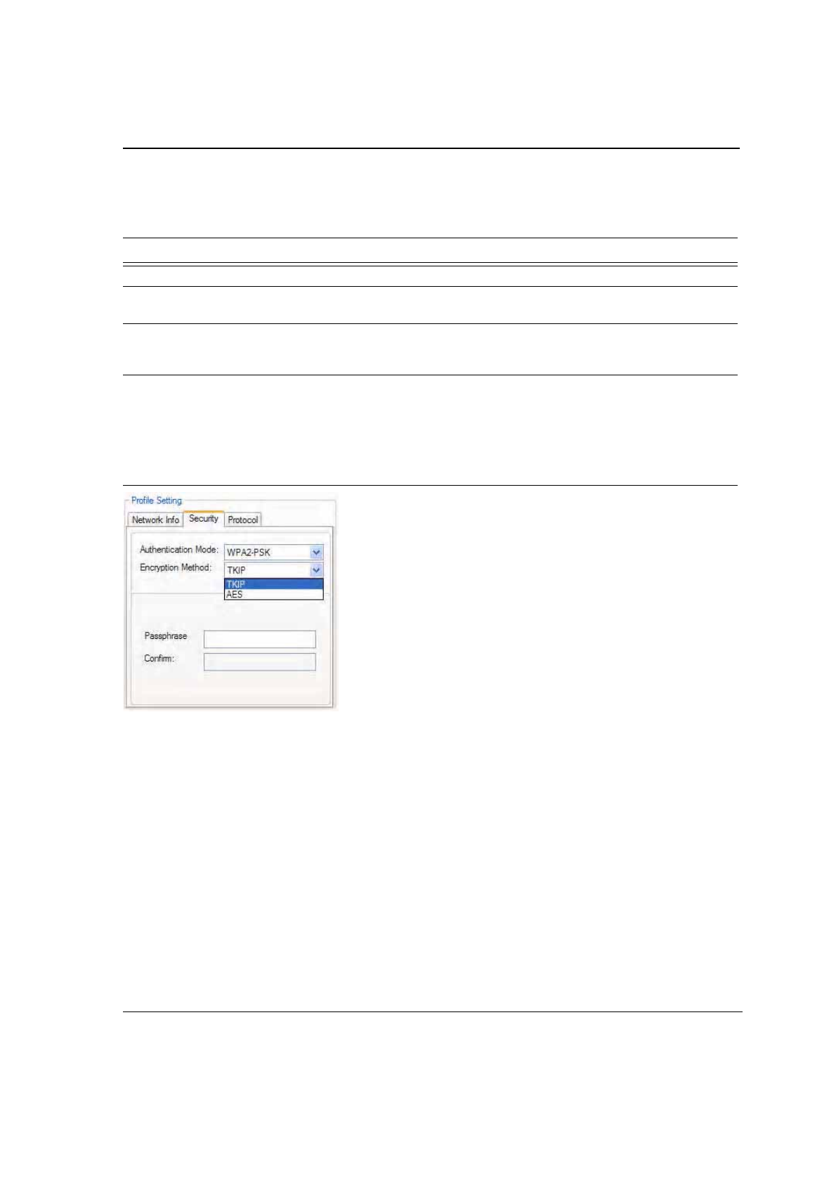
3.2.2.5 TKIP/AES Settings
If TKIP/AES is selected and the authentication mode is WPA-PSK or WPA2-PSK, the security tab displays the
TKIP/AES passphrase settings. Enter the passphrase into the Passphrase and Confirm boxes. Click OK.
Figure 37: TKIP/AES Settings
Table 8: WEP Key Configuration
Fields Description
Key Format Either ASCII characters or hexadecimal digits
Key Size 40-bit, 5 character ASCII key size (40-bit, 10 character hexadecimal)
104-bit, 13 character ASCII key size (104-bit, 26 character hexadecimal)
Transmit Keys There are four transmit keys. The key value is in ASCII or hexadecimal,
depending on the format selected. The WEP key size shown depends on the
key size selected.
J20H018
802.11b/g WLAN Module User Guide
Doc. No. MV-S800245-00 Rev. C CONFIDENTIAL Copyright © 2005 Foxconn
Page 38 Document Classification: Proprietary May 26, 2005, 2.00
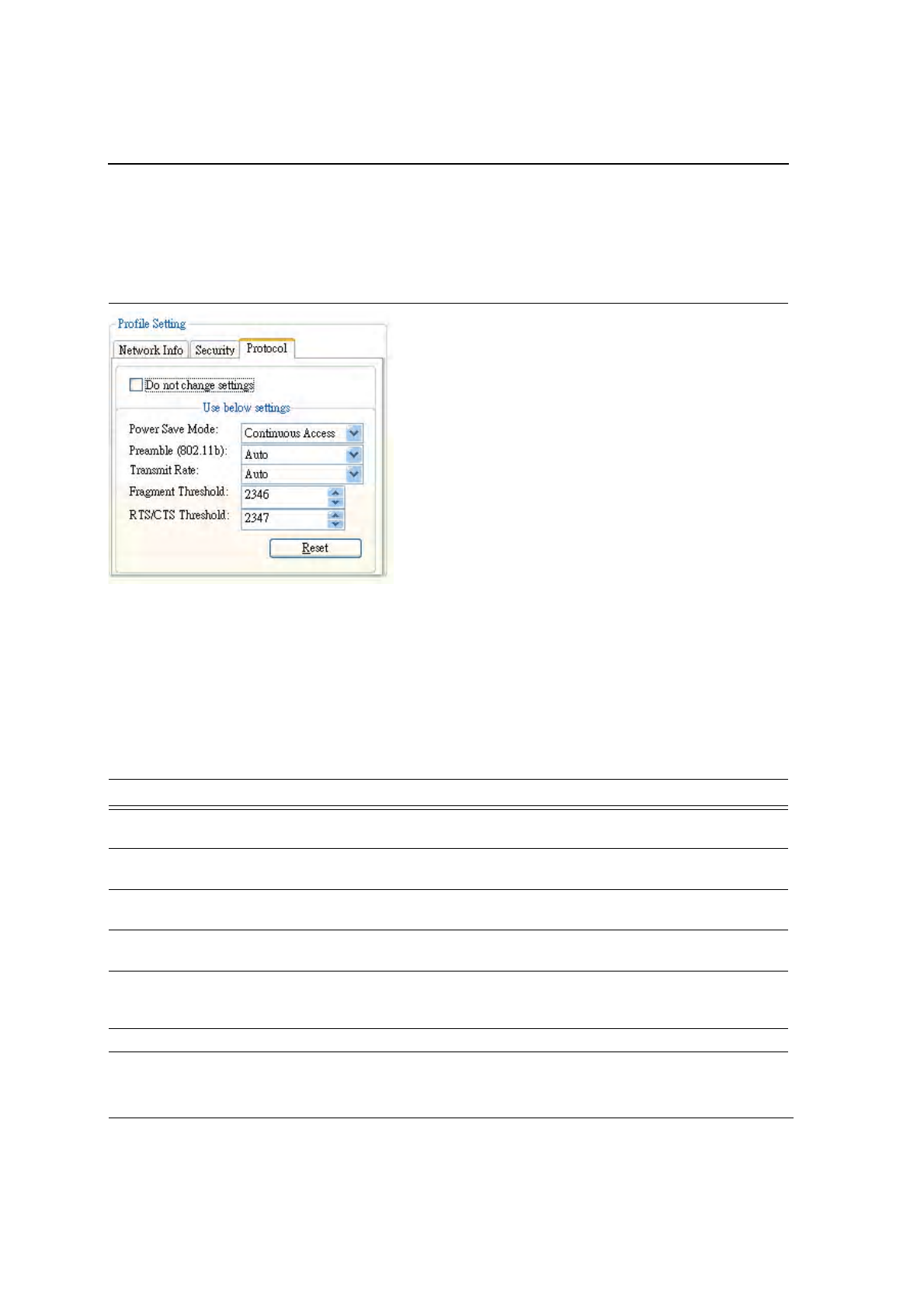
3.2.3 Profile Setting—Protocol
The protocol tab allows you to set or change the protocol information.
Figure 38: Profile Setting—Protocol Window
DO NOT CHANGE SETTINGS
If this box is checked, the protocol setting is not changed when the profile is applied.
USE BELOW SETTINGS
When the Do not change setting box is unchecked, the protocol settings include:
Table 9: Protocol Window Description
Fields Description
Power Save Mode Sets the power mode. Available options are Continuous Access or Max Power
Save. The default is Continuous Access.
Preamble (802.11b) Sets the Radio Preamble to Auto, short, or Long. This option takes effect only
when attaching to an 802.11b network.
Transmit Rate The range of the data rate depends on the type of AP that the client card is
connected to. The default setting is Auto Select.
Fragment Threshold Sets the fragmentation threshold (the size that packets are fragmented into for
transmission). The default setting is 2346.
RTS/CTS Threshold Sets the packet size at which the AP issues a Request-To-Send (RTS)
or Clear-to-Send (CTS) frame before sending the packet. The default setting
is 2347.
Reset button Resets the protocol settings to their default values.
Configuration Utility User Interface
Site Survey Tab
Copyright © 2005 Foxconn CONFIDENTIAL Doc. No. MV-S800245-00 Rev. C
May 26, 2005, 2.00 Document Classification: Proprietary Page 39
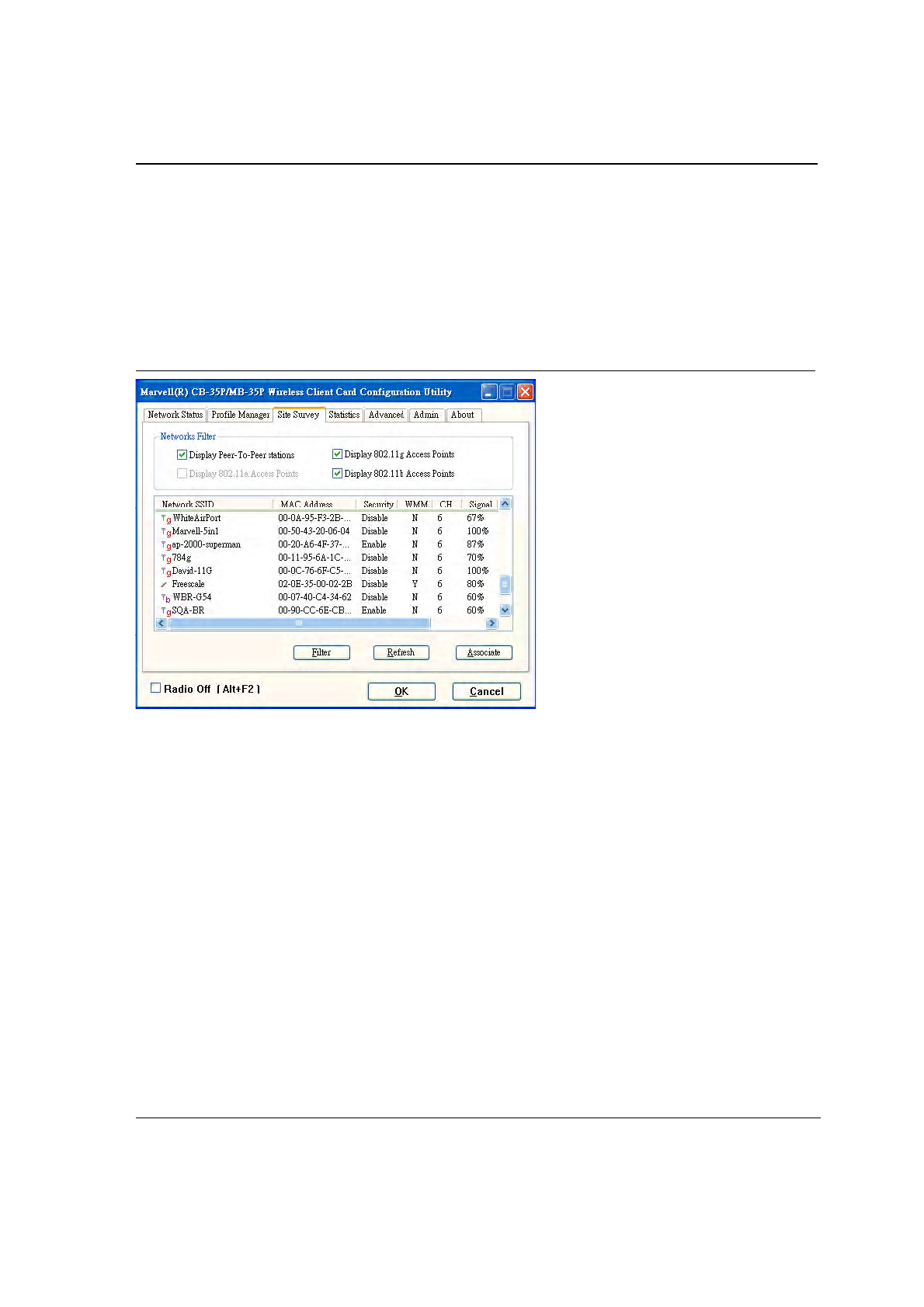
3.3 Site Survey Tab
Clicking on the Site Survey tab displays the Site Survey dialog box.
There are two ways to connect to a network through the Site Survey Window:
•
Double click on the network
•
Select network and click the Associate button
Figure 39: Site Survey Tab
This tab shows a list of all of the peer-to-peer and AP stations within range of the adapter.
CB-35P/MB-35P
Wireless Adapter User Guide
Doc. No. MV-S800245-00 Rev. C CONFIDENTIAL Copyright © 2005 Foxconn
Page 40 Document Classification: Proprietary May 26, 2005, 2.00
3.3.1 Site Survey—Access Point Filter
This section is used to customize which sites are displayed in the Site Survey list window:
•
Display Peer-To-Peer stations—checking this box displays all of the peer-to-peer stations within range.
•
Display 802.11a Access Points—disabled (not supported in CB-35P/MB-35P).
•
Display 802.11g Access Points—checking this box displays all of the 802.11g APs within range.
•
Display 802.11b Access Points—checking this box displays all of the 802.11b APs within range.
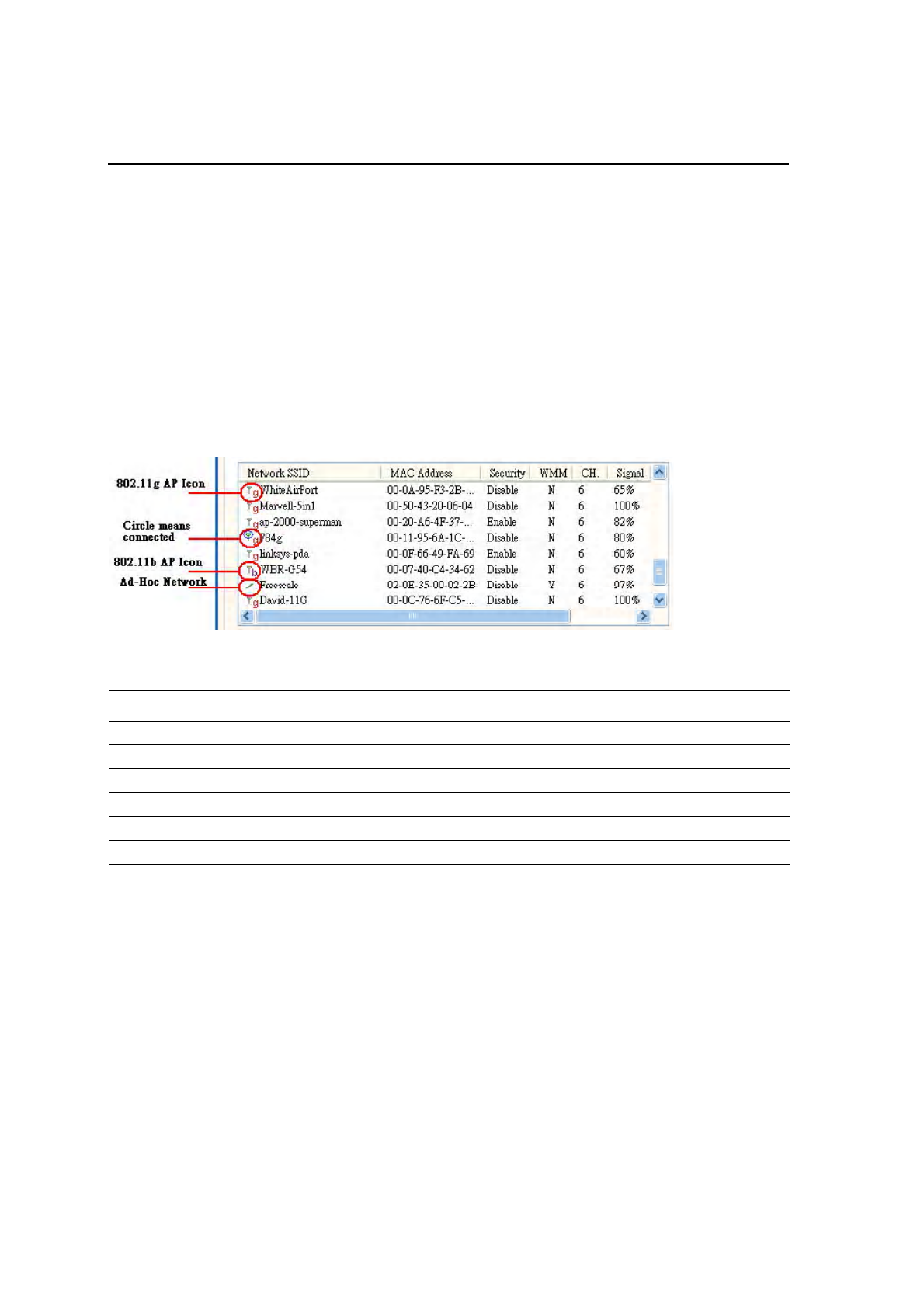
3.3.2 Site Survey—List Window
This window reports information on the Ad-Hoc or AP stations detected:
Figure 40: Site Survey List Window
Table 10: Site Survey List Window Description
Fields Description
Network SSID Network SSID label; i.e., the Network Name. The Network Name is a text string.
MAC Address MAC address, a hardware address that uniquely identifies each node of a network.
Security Security enabled or disabled
CH Channel used by the detected device
WMM Wireless Multimedia Enhancements (WMM) supported by the detected device.
Signal Signal strength of the detected device as a percentage
Icons The following icons may be displayed on the left side of the Network SSID column:
•
An antenna icon with a superscript b indicates an 802.11b AP.
•
An antenna icon with a superscript g indicates an 802.11g AP.
•
A circle around the icon means the adapter is connected to this network.
•
A slash icon indicate an Ad-Hoc network.
Configuration Utility User Interface
Site Survey Tab
Copyright © 2005 Foxconn CONFIDENTIAL Doc. No. MV-S800245-00 Rev. C
May 26, 2005, 2.00 Document Classification: Proprietary Page 41
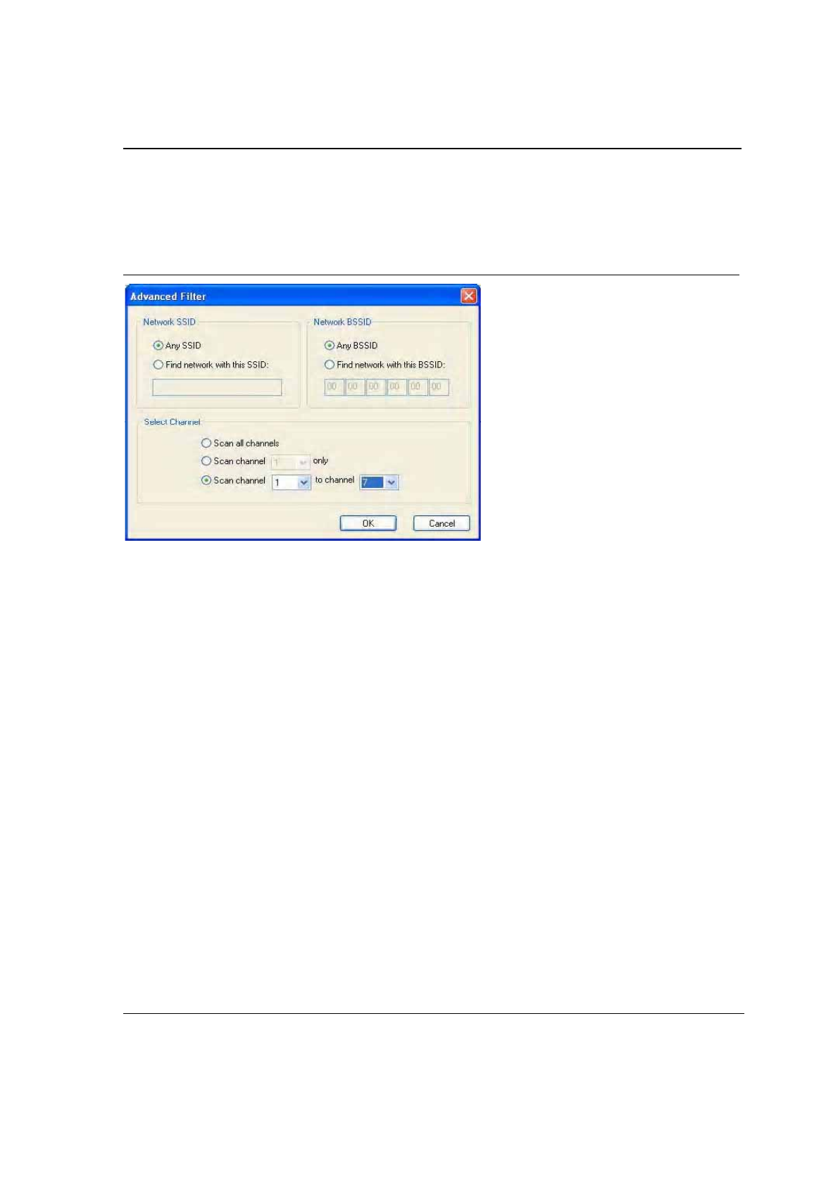
3.3.3 Site Survey—Filter Button
Clicking the Filter button displays the Advanced Filter dialog box:
Figure 41: Site Survey Filter Button Window
3.3.3.1 Network SSID
•
Any SSID—if selected, no specific SSID is used when scanning for available network in the area.
•
Find network with this SSID—if selected, the utility searches for the specified SSID.
3.3.3.2 Network BSSID
•
Any BSSID—if selected, no specific BSSID is used when scanning for available network in the area.
•
Find network with this BSSID—if selected, the utility searches for the specified BSSID.
3.3.3.3 Select Channel
•
Scan all channels—all channels are scanned when searching for the available networks in the area.
•
Scan channel Only—only specified channel is scanned when searching for the available networks in the
area.
•
Scan Channel to Channel—a range of channels are scanned when searching for the available networks in
the area.
3.3.4 Site Survey—Refresh Button
Clicking the Refresh button requests a survey of the wireless networks in the area.
3.3.5 Site Survey—Associate Button
Select an available network, and then click the Associate button requests to establish a connection.
J20H018
802.11b/g WLAN Module User Guide
Doc. No. MV-S800245-00 Rev. C CONFIDENTIAL Copyright © 2005 Foxconn
Page 42 Document Classification: Proprietary May 26, 2005, 2.00
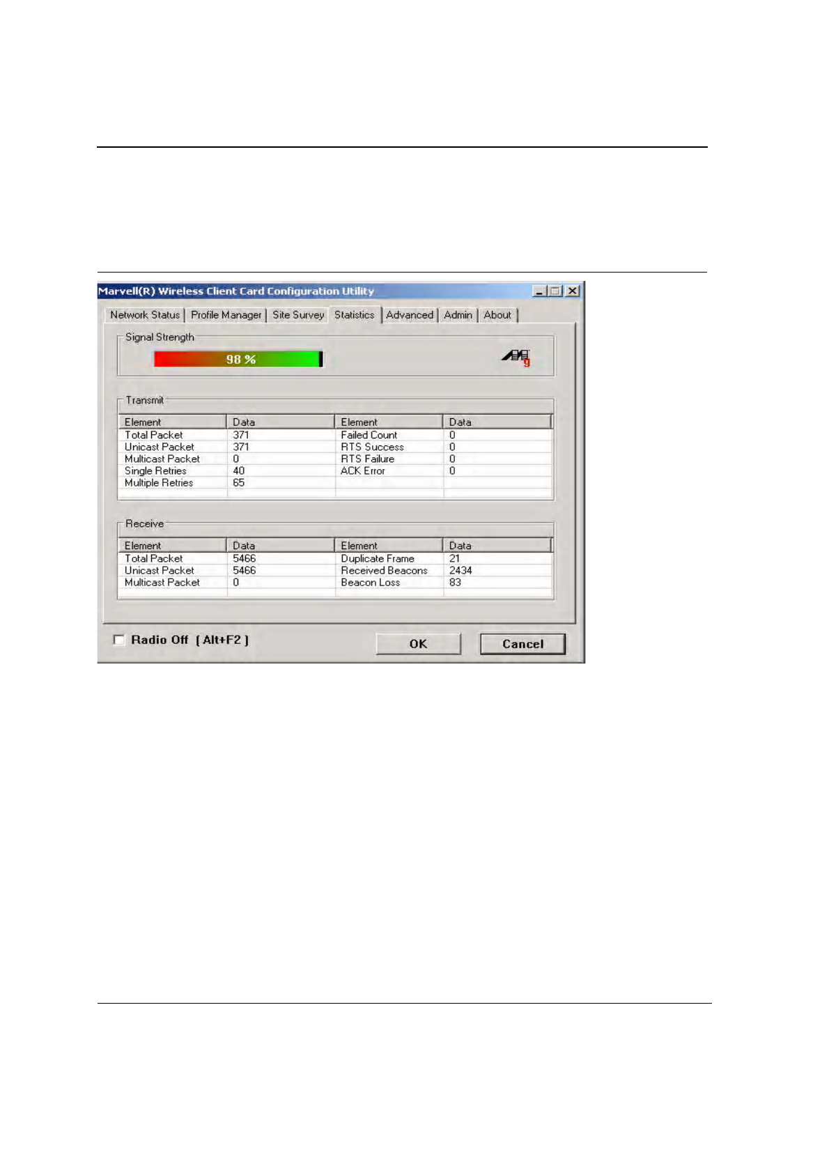
3.4 Statistics Tab
Clicking on the Statistics tab displays the statistics of the current connect session:
Figure 42: Statistics Window
3.4.1 Signal Strength
The color-coded Signal Strength bar displays the signal strength of the last packet received by the adapter. Signal
strength is reported as a percentage. A signal in the red indicates a bad connection. A signal in the green indicates
a good connection.
Configuration Utility User Interface
Statistics Tab
Copyright © 2005 Foxconn CONFIDENTIAL Doc. No. MV-S800245-00 Rev. C
May 26, 2005, 2.00 Document Classification: Proprietary Page 43
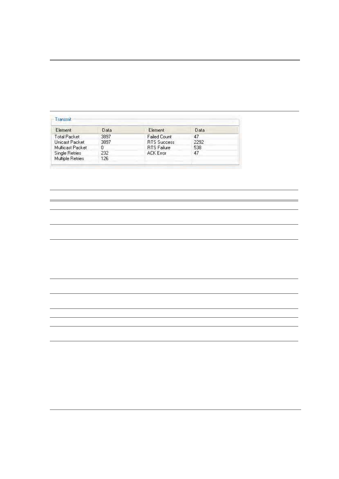
3.4.2 Transmit Window
The Transmit window displays the information on the packets sent:
Figure 43: Transmit Window
Table 11: Transmit Window Description
Fields Description
Total Packet Reports the total number of packets transmitted.
Unicast Packet Reports the number of packets transmitted by the adapter that were destine for a
single network node.
Multicast Packet Reports the number of packets transmitted by the adapter that were destine for more
than one network node.
Single Retries Reports the number of packets that require one retry before the adapter received an
acknowledgement.
NOTE:After the adapter sends a packet, it waits for an acknowledge from the
receiving radio to confirm that the packet was successfully received. If the
acknowledge is not received within a specified period of time, the adapter
retransmits the packet.
Multiple Retries Reports the number of packets that require more than one retry before the adapter
received an acknowledgement.
Failed Count Reports the number of packets that were not successfully transmitted because the
adapter did not receive an acknowledgement within the specified period of time.
RTS Success Reports the number of RTS attempts that were successful.
RTS Failure Reports the number of RTS attempts that were not successful.
ACK Error Reports the number of unicast transmit attempts for which no acknowledgement was
received.
J20H018
802.11b/g WLAN Module User Guide
Doc. No. MV-S800245-00 Rev. C CONFIDENTIAL Copyright © 2005 Foxconn
Page 44 Document Classification: Proprietary May 26, 2005, 2.00
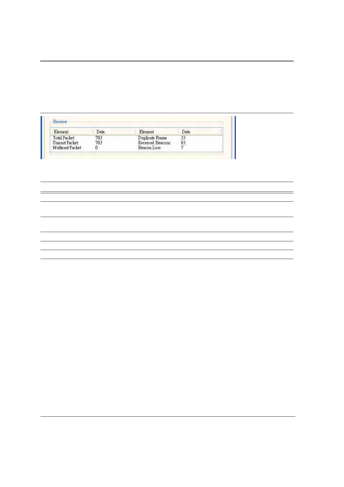
3.4.3 Receive Window
The Receive window displays the information on the packets received:
Figure 44: Receive Window
Table 12: Receive Window Description
Fields Description
Total Packet Reports the total number of packets received.
Unicast Packet Reports the number of packets received by the adapter that were destined for
a single network node.
Multicast Packet Reports the number of packets received by the adapter that were destined for
more than one network node.
Duplicate Frame Reports the number of duplicate frames received.
Received Beacons Reports the number of beacons received after association is established.
Beacon Loss Reports the number of missing beacons after association is established.
Configuration Utility User Interface
Advanced Tab
Copyright © 2005 Foxconn CONFIDENTIAL Doc. No. MV-S800245-00 Rev. C
May 26, 2005, 2.00 Document Classification: Proprietary Page 45
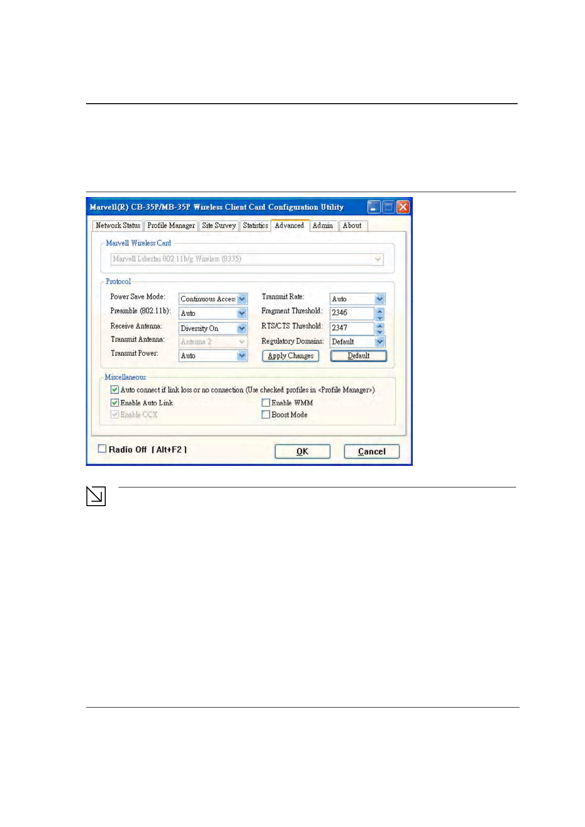
3.5 Advanced Tab
Clicking on the Advanced tab displays the Advanced dialog box.
Figure 45: Advanced Tab
Note
The Advanced Tab page is not accessible when Zero Configuration is enabled.
3.5.1 Advanced Tab—Foxconn Wireless Card
This window reports the type of Foxconn WLAN adapter installed.
J20H018
802.11b/g WLAN Module User Guide
Doc. No. MV-S800245-00 Rev. C CONFIDENTIAL Copyright © 2005 Foxconn
Page 46 Document Classification: Proprietary May 26, 2005, 2.00
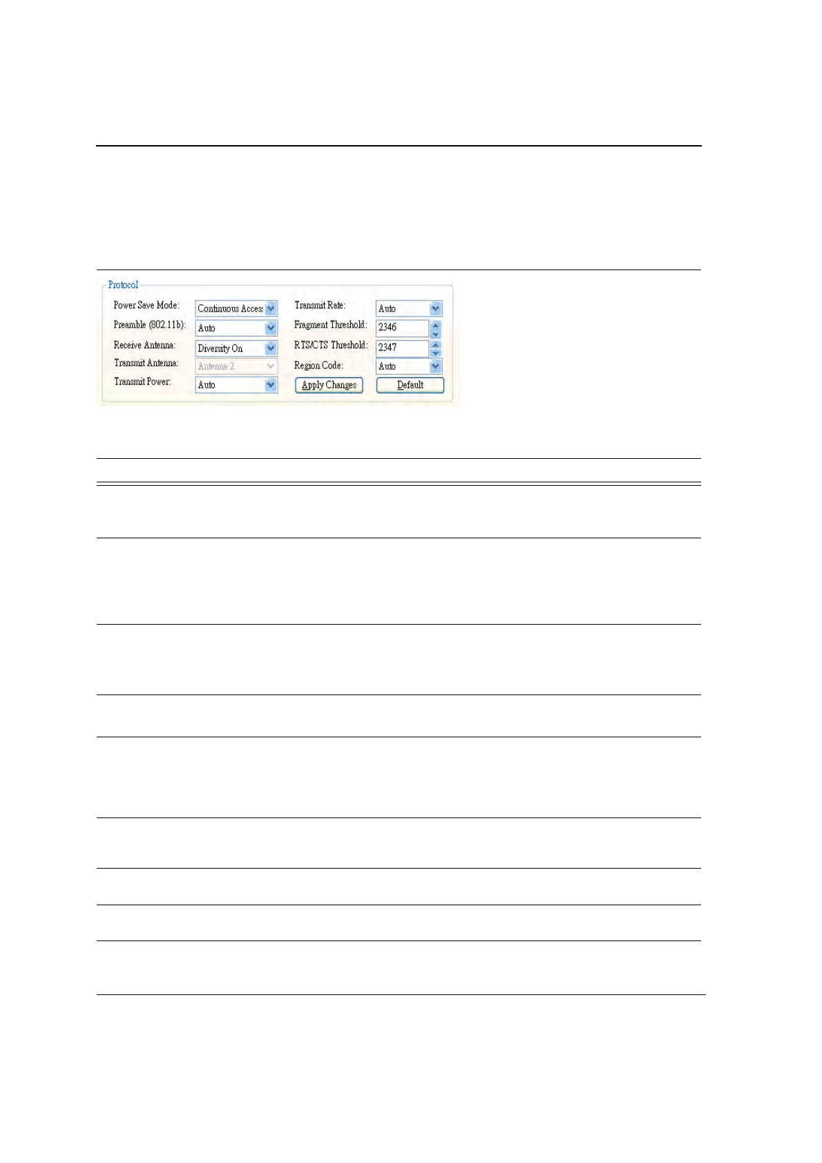
3.5.2 Advanced Tab—Protocol
This section of the Advanced tab sets the Protocol options:
Figure 46: Protocol Window
Table 13: Advanced Tab Protocol Window Description
Fields Description
Power Save Mode Sets the power mode:
•
Continuous Access
•
Max Power Save
Preamble (802.11b) Sets the radio preamble (takes effect only when attaching to 802.11b
networks):
•
Auto
•
Short
•
Long
Receive Antenna Sets the Receive Antenna mode, either:
•
Diversity On
•
Diversity Off
•
Transmit Antenna Fixed at Antenna 2
Transmit Power Sets the power mode:
•Auto
•High
•Medium
• Low
Transmit Rate Data transmit rate
The range of the data rate depends on the type of AP that the client card is
connected to. The default setting is Auto.
Fragment Threshold Sets the fragmentation threshold (i.e., the size that packets are fragmented
into for transmission). The default setting is 2346.
RTS/CTS Threshold Sets the packet size at which the AP issues a RTS (or CTS) frame before
sending the packet. The default setting is 2347.

Configuration Utility User Interface
Advanced Tab
Copyright © 2005 Foxconn CONFIDENTIAL Doc. No. MV-S800245-00 Rev. C
May 26, 2005, 2.00 Document Classification: Proprietary Page 47
Region Code Sets the regulatory domains:
• Default
• FCC/IC
•Spain
• France
•MKK
• MKK1
• Israel
•Other
NOTE: Set Default to select region as manufacture default. Set “Other” to
customize frequency channels.
Apply Changes or Default
buttons
Configures the options according to the changes entered or applies the
default values.
Table 13: Advanced Tab Protocol Window Description
Fields Description

J20H018
802.11b/g WLAN Module User Guide
Doc. No. MV-S800245-00 Rev. C CONFIDENTIAL Copyright © 2005 Foxconn
Page 48 Document Classification: Proprietary May 26, 2005, 2.00
3.5.3 Advanced Tab—Miscellaneous
Figure 47: Miscellaneous Window
Table 14: Advanced Tab Miscellaneous Window
Field Description
Auto Correct if link or no connection (Use
checked profiles in <Profile Manager>
Uncheck this box to disable the auto-configuration feature.
Whenever there is a link loss, auto-configuration tries to establish
a connection using the checked profiles in the Profile Manager
window.
Enable AutoLink Check this box to enable/disable the AutoLink feature (see
Section 2.4 "AutoLink" on page 16).
Enable CCX Fixed CCX enabled.
Enable WMM Check this box to enable/disable the Wireless Multimedia
Enhancements (WMM) feature.
Boost Mode Check this box for performance enhancement.
Configuration Utility User Interface
Admin Tab
Copyright © 2005 Foxconn CONFIDENTIAL Doc. No. MV-S800245-00 Rev. C
May 26, 2005, 2.00 Document Classification: Proprietary Page 49
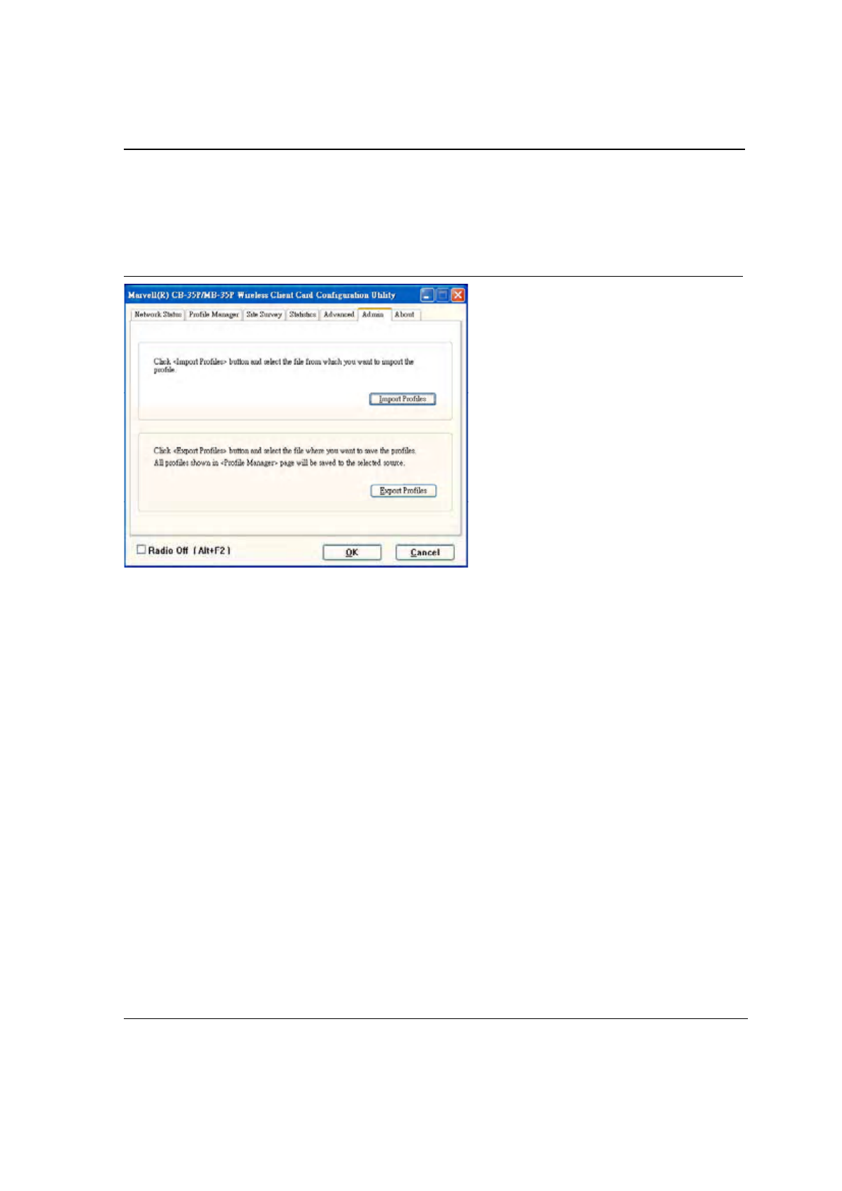
3.6 Admin Tab
Clicking the Admin tab displays the Admin dialog box. This tab allows you to import and export profiles.
Figure 48: Configuration Utility Window with Admin Tab
3.6.1 Admin Tab—Import Profiles
To import a profile:
1. Click the Import Profiles button.
2. Select the path and filename of the profile.
3. Click Open.
3.6.2 Admin Tab—Export Profiles
To export a profile:
1. Click the Export Profiles button.
2. Select or enter the path and filename of the profile.
3. Click Save.
J20H018
802.11b/g WLAN Module User Guide
Doc. No. MV-S800245-00 Rev. C CONFIDENTIAL Copyright © 2005 Foxconn
Page 50 Document Classification: Proprietary May 26, 2005, 2.00
THIS PAGE INTENTIONALLY LEFT BLANK
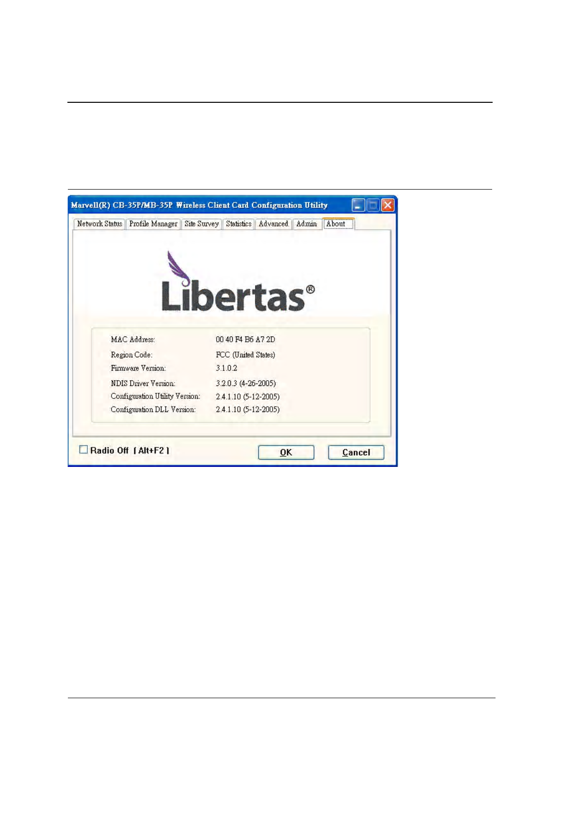
3.7 About Tab
Clicking on the About tab displays the About dialog box, as shown in the following example.
Figure 49: About Tab Window

Acronyms and Abbreviations
Copyright © 2005 Foxconn CONFIDENTIAL Doc. No. MV-S800245-00 Rev. C
May 26, 2005, 2.00 Document Classification: Proprietary Page 51
Appendix A. Acronyms and Abbreviations
Table 15: Acronyms and Terms
Term Definition
802.11 A family of specifications developed by the IEEE for WLAN technology.
802.11a An extension to 802.11 WLAN standard that provides up to 54 Mbps transmission in
the 5 GHz UNII radio band.
802.11b An extension to 802.11 WLAN standard that provides up to 11 Mbps transmission in
the 2.4 GHz ISM radio band. 802.11b uses DSSS modulation.
802.11g An extension to 802.11 WLAN standard that provides up to 54 Mbps transmission in
the 2.4 GHz ISM radio band. 802.11g uses OFDM modulation and is backwards
compatible with 802.11b.
AC Admission Control
Ad-Hoc A group of computers each with wireless adapters, connected as an independent
WLAN.
AES Advanced Encryption Standard
AP Access Point
ATIM Announced Traffic Indication Message
BBP Baseband Processor
BSS Basic Service Set
BSSID Basic Service Set ID
CardBus The 32-bit version of the PCMCIA PC Card standard. In addition to supporting a wider
bus (32 bits instead of 16 bits), CardBus also support bus mastering and operation
speeds up to 33 MHz.
CCMP Counter mode with Cipher Block Chaining Message protocol
CCX Cisco Compatible Extensions
CE European health and safety label
CF CompactFlash
CTS Clear to Send
DGT Directorate General of Telecommunications Taiwan
DHCP Dynamic Host Configuration Protocol
DMA Direct Memory Access
DRV Driver
DSL Digital Subscriber Line
DSR Delayed Service Routine

J20H018
802.11b/g WLAN Module User Guide
Doc. No. MV-S800245-00 Rev. C CONFIDENTIAL Copyright © 2005 Foxconn
Page 52 Document Classification: Proprietary May 26, 2005, 2.00
DSSS Direct Sequence Spread Spectrum. DSSS is one of two types of spread spectrum
radio. The other is frequency-hopping spread spectrum (FHSS).
DTIM Delivery Traffic Indication Message
EAP Extensible Authentication Protocol
EAPOL EAP Over LAN
EAP-TLS EAP Transport Layer Security (RFC2716)
ESSID Extended Service Set Identifier
G Protection Secures the 802.11g client’s traffic in an environment where both 80211g and 802.11b
clients are transmitting.
GUI Graphical User Interface
IAPP International Association of Privacy Professionals
IBSS Independent Basic Service Set (“Ad-Hoc”)
ICV Integrity Check Vector
IEEE Institute of Electrical and Electronics Engineers
LAN Local Area Network
MAC Medium Access Controller
MIC Message integrity check
MSDU MAC Service Data Unit
NAS Network Access Server
NDIS Network Driver Interface Specification
NIC Network Interface Card
OCB Offset Codebook Block mode
OFDM Orthogonal Frequency Division Multiplexing
OID Object Identifier
OS Operating System
PCI Peripheral Component Interconnect
PCMCIA Personal Computer Memory Card International Association
PEAP Protected EAP
PHY Physical Layers
PMK Pairwise Master Key
PSK Pre-Shared Keys
PWK Pair Wise Key
QoS Quality of Service
RADIUS Remote Authentication Dial In User Service
Table 15: Acronyms and Terms
Term Definition

Acronyms and Abbreviations
Copyright © 2005 Foxconn CONFIDENTIAL Doc. No. MV-S800245-00 Rev. C
May 26, 2005, 2.00 Document Classification: Proprietary Page 53
RF Radio Frequency
RSN Robust Secure Network
RSSI Received Signal Strength Indication
RTS Request to Send
SoC System-on-Chip
SPI Serial Peripheral Interface
SSID Service Set Identifier. A 32-character unique identifier attached to the header of
packets sent over a WL/AN that acts as a password when a mobile device tries to
connect to the BSS.
TCP/IP Transmission Control Protocol/Internet Protocol
TIM Traffic Information Map
TKIP Temporal Key Integrity Protocol
TLS Transport Layer Security
TSC Transmit Sequence Counter
UART Universal Asynchronous Receiver / Transmitter
USB Universal Serial Bus
WAN Wide Area Network
WDS Wireless Distribution System
WEP Wired Equivalent Privacy. A security protocol for WLANs defined in the IEEE 802.11
standard.
Wi-Fi Wireless Fidelity (IEEE 802.11)
WLAN Wireless Local Area Network
WMM Wi-Fi Multimedia Enhancements
WOW Wake on Wireless
WPA Wi-Fi Protected Access
WPA2 Wi-Fi Protected Access 2. The next generation of Wi-FI security, based on the final
802.11i standard.
WPA2-PSK Wi-Fi Protected Access 2-Pre-shared Keys
WPA-PSK Wi-Fi Protect Access-Pre-shared Keys
WZC Wireless Zero Configuration System
Table 15: Acronyms and Terms
Term Definition

Federal Communication Commission Interference Statement
This equipment has been tested and found to comply with the limits for
a Class B digital device, pursuant to Part 15 of the FCC Rules. These
limits are designed to provide reasonable protection against harmful
interference in a residential installation. This equipment generates,
uses and can radiate radio frequency energy and, if not installed and
used in accordance with the instructions, may cause harmful
interference to radio communications. However, there is no guarantee
that interference will not occur in a particular installation. If this
equipment does cause harmful interference to radio or television
reception, which can be determined by turning the equipment off and
on, the user is encouraged to try to correct the interference by one of
the following measures:
- Reorient or relocate the receiving antenna.
- Increase the separation between the equipment and receiver.
- Connect the equipment into an outlet on a circuit different from
that
to which the receiver is connected.
- Consult the dealer or an experienced radio/TV technician for
help.
This device is intended only for OEM integrators under the following
conditions:
1) The antenna must be installed such that 20 cm is maintained between the
antenna and users, and
2) The transmitter module may not be co-located with any other transmitter
or antenna.
As long as 2 conditions above are met, further transmitter test will not be
required. However, the OEM integrator is still responsible for testing their end-
product for any additional compliance requirements required with this module
installed (for example, digital device emissions, PC peripheral requirements,
etc.).
IMPORTANT NOTE: In the event that these conditions can not be met (for
example certain laptop configurations or co-location with another transmitter),
then the FCC authorization is no longer considered valid and the FCC ID can
not be used on the final product. In these circumstances, the OEM integrator
will be responsible for re-evaluating the end product (including the transmitter)
and obtaining a separate FCC authorization.
Labeling Rule for the End Product Which Integrate this Module
This transmitter module is authorized only for use in device where the
antenna may be installed such that 20 cm may be maintained between the
antenna and users The final end product must be labeled in a visible area
with the following statement: “Contains TX FCC ID: MCLJ20H018”.
Information Needed to be Included in the Users Manual of the End Product
The users manual for OEM integrators must include the following information
in a prominent location “ IMPORTANT NOTE: To comply with FCC RF
exposure compliance requirements, the antenna used for this transmitter
must be installed to provide a separation distance of at least 20 cm from all
persons and must not be co-located or operating in conjunction with any other
antenna or transmitter.”
IC statement
"This device has been designed to operate with an antenna having a maximum gain of [2] dB. Antenna
having a higher gain is strictly prohibited per regulations of Industry Canada. The required antenna
impedance is [ 50 ] ohms."
"To reduce potential radio interference to other users, the antenna type and its gain should be so chosen
that the equivalent isotropically radiated power (EIRP) is not more than that required for successful
communication".