HON HAI PRECISION IND J20H064 WiFi+ BT Module User Manual J20H064 00 user mannual
HON HAI Precision Ind. Co., Ltd. WiFi+ BT Module J20H064 00 user mannual
User Manual.pdf
1
Project Name WiFi+ BT Module
Approval Sheet Rev. 1.0
Foxconn Part No. J20H064
Prepared by Reviewed by Approved by
Shu-yu Li Xue-dong Jiang
HON HAI PRECISION IND. CO., LTD.
No.2, 2nd Dong Huan Road, 10th
YouSong lndustrial District, Longhua
Town, Baoan, ShenZhen
User Manual
WiFi+ BT Module

2
CONTENTS
1 PRODUCT INTRODUCTION .............................................................. 3
1.1 APPLICATION SCOPE ..................................................................... 3
2 MODULE HARDWARE OVERVIEW ........................................................ 4
2.1 BLOCK DIAGRAM ........................................................................ 4
2.2 FEATURES ............................................................................. 4
2.3 INTERFACE AND CONNECTOR .............................................................. 4
3 ELECTRICAL SPECIFICATION ............................................................ 6
3.1 ABSOLUTE MAXIMUM RATING ............................................................... 6
3.2 RECOMMENDED OPERATING RATING ......................................................... 6
3.3 DC CHARACTERISTICS ................................................................... 6
3.4 ESD INFORMATION ...................................................................... 6
3.5 ENVIRONMENT STORAGE CONDITION ........................................................ 6
4 RF SPECIFICATION ..................................................................... 7
4.1 IEEE802.11B .......................................................................... 7
4.2 IEEE802.11G .......................................................................... 8
4.3 802.11N HT20 ......................................................................... 9
4.4 BLUETOOTH STANDARD SPECIFICATIONS ..................................................... 9
5 MECHANICAL SPECIFICATIONS......................................................... 13
5.1 SHIELDING COVER DIMENSION ............................................................ 13
5.2 PCB ASSEMBLY DIMENSION .............................................................. 14

3
1 Product Introduction
The J20H064 802.11b/g/n+Bluetooth4.0 module provides wireless modem
functionality utilizing direct sequence spread spectrum and OFDM/CCK technology. This
module is based on Marvell 88W8766P solution which is integrated 2.4GHz IEEE802.11
b/g/n (MAC/baseband/radio), Bluetooth 4.0 + High speed and power amplifiers (PA).
1.1 Application scope
The wireless LAN is compliant to IEEE 802.11b and IEEE 802.11g and IEEE 802.11n
standard. The data rate of 802.11b is up to 11Mbps and fallback rates of 5.5, 2, 1Mbps.
The data rate of 802.11g is up to 54Mbps and fallback rates of 48,36,24,18,12,9, 6Mbps.
The data rate of 802.11n HT20 is up to 65Mbps and fallback rates of 58.5, 52, 39, 26, 19.5,
13, 6.5Mbps;
4
2 Module Hardware Overview
2.1 Block Diagram
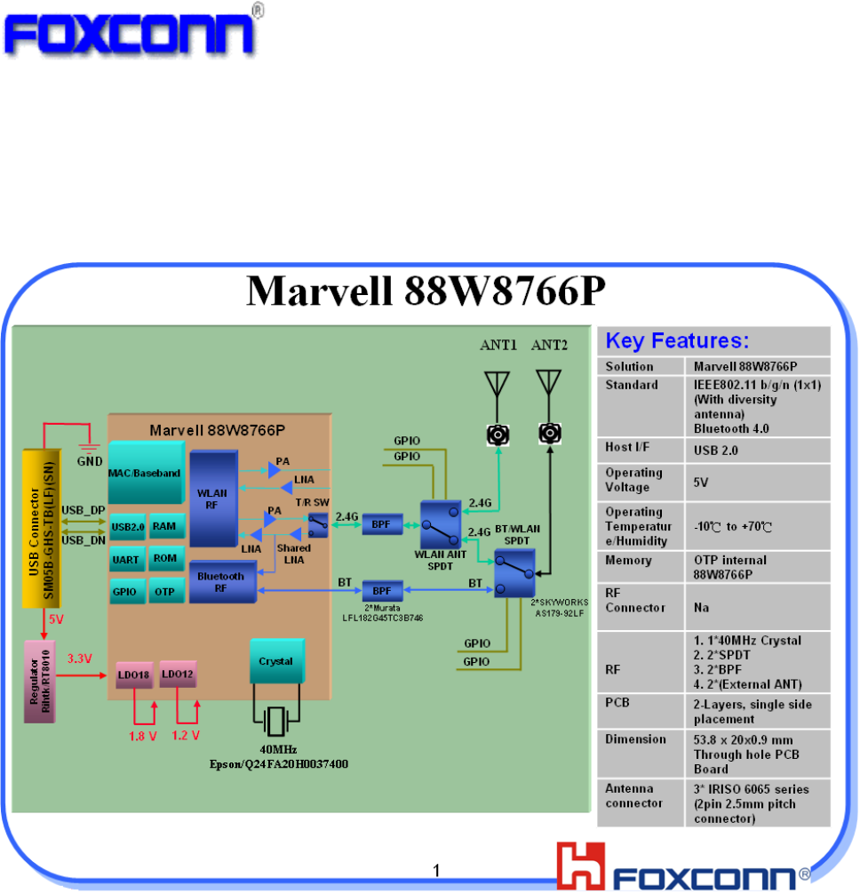
The general HW architecture is shown below Figure:
.
Module Block Diagram
2.2 Features
♦ IEEE802.11b/g/n (1X1) and Bluetooth 4.0 based on Marvell 88W8766P solution.
♦ USB 2.0 Interface, High and Full Speeds supported.
♦ Module is powered by the host with a 5.0V +/- 5% supply.
♦ External PCB printed antennas.
♦ Two SPDT switch for antenna diversity and Bluetooth function.
♦ 2 layers single side design, through hole PCB design with halogen free FR4
material
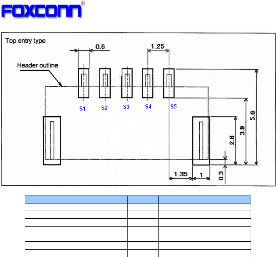
2.3 Interface and Connector
♦ Pin definition:
♦ Vendor: JST
♦ Vendor P/N: SM05B-GHS-TB(LF)(SN)
5
Pin Number Symbol Name Status Pin definition
1 GND Ground
2 DP I/O USB positive data
3 DM I/O USB negative data
4 UV+ P USB +5V power input
5 GND Ground
S1 GND Ground
S2 GND Ground
6
3 Electrical Specification
3.1 Absolute maximum rating
Element Symbol Min Typ Max Unit
DC supply voltage UV+ 5.0
6.5 (V)
3.2 Recommended operating rating
Element Symbol Min Typ Max Unit
DC supply voltage UV+ 4.5 5.0
5.5 (V)
3.3 DC Characteristics
Symbol Parameter Min Typ Max Unit
UV+
Supply voltage 4.5 5.0 5.5 (V)
Tx Current(1M/15dBm) 200 280 400 (mA)
Tx Current(11M/15dBm) 200 280 400 (mA)
Tx Current(6M/15dBm) 200 280 400 (mA)
Tx Current(54M/15dBm) 200 280 400 (mA)
Tx Current(MCS0/15Bm/HT20) 200 280 400 (mA)
Tx Current(MCS7/15dBm/HT20) 200 280 400 (mA)
Rx Current 90 (mA)
Bluetooth TX 110 (mA)
Bluetooth RX -- 110 (mA)
3.4 ESD Information
Mode Level Unit
HBM +/-1500 V
MM +/-200 V
3.5 Environment Storage Condition
Environment condition
Temperature Operating Temperature: -10 deg.C ~70 deg.C
Storage Temperature: -40 deg.C ~80 deg.C
Humidity Operating Humidity: 20% ~90%
Storage Humidity: 20% ~90%
7
4 RF Specification
4.1 IEEE802.11b
Items Contents
Specification IEEE802.11b
Mode DSSS / CCK
Channel CH1 to CH13
Data rate 1, 2, 5.5, 11Mbps
TX Characteristics Min. Typ. Max. Unit
1. Power Levels (Calibrated)
1) Target Power@1Mbps 13.5 15 16.5 dBm
2) Target Power@2Mbps
13.5 15 16.5 dBm
3) Target Power@5.5Mbps
13.5 15 16.5 dBm
4) Target Power@11Mbps
13.5 15 16.5 dBm
2. Spectrum Mask @16dBm
1) fc-33MHz < f < fc-22MHz - - -50 dBr
2) fc-22MHz < f < fc-11MHz - - -30 dBr
3) fc+11MHz < f < fc+22MHz - - -30 dBr
4) fc+22MHz < f < fc+33MHz - - -50 dBr
3. Frequency Error -15 - +5 ppm
4 Modulation Accuracy(EVM)@16dBm
1) 1Mbps - -10 dB
2) 2Mbps - -10 dB
3) 5.5Mbps - -10 dB
4) 11Mbps - -10 dB
RX Characteristics Min. Typ. Max. Unit
5 Minimum Input Level Sensitivity
1) 1Mbps (FER≦8%) - -95 -92 dBm
2) 2Mbps (FER≦8%) - -92 -89 dBm
3) 5.5Mbps (FER≦8%) - -90 -87 dBm
4) 11Mbps (FER≦8%) - -88 -85 dBm
6 Maximum Input Level (FER≦8%) -10 -5 - dBm

8
4.2 IEEE802.11g
Items Contents
Specification IEEE802.11g
Mode OFDM
Channel CH1 to CH13
Data rate 6, 9, 12, 18, 24, 36, 48, 54Mbps
TX Characteristics Min. Typ. Max. Unit
1. Power Levels (Calibrated)
1) Target Power@6Mbps
13.5 15 16.5 dBm
2) Target Power@9Mbps
13.5 15 16.5 dBm
3) Target Power@12Mbps
13.5 15 16.5 dBm
4) Target Power@18Mbps
13.5 15 16.5 dBm
5) Target Power@24Mbps
13.5 15 16.5 dBm
6) Target Power@36Mbps
13.5 15 16.5 dBm
7) Target Power@48Mbps
13.5 15 16.5 dBm
8) Target Power@54Mbps
13.5 15 16.5 dBm
2. Spectrum Mask @14dBm
1) at fc +/- 11MHz - - -20 dBr
2) at fc +/- 20MHz - - -28 dBr
3) at fc > +/-30MHz - - -40 dBr
3 Modulation Accuracy(EVM)@14dBm
1) 6Mbps - - -5 dB
2) 9Mbps - - -8 dB
3) 12Mbps - - -10 dB
4) 18Mbps - - -13 dB
5) 24Mbps - - -16 dB
6) 36Mbps - - -19 dB
7) 48Mbps - - -22 dB
8) 54Mbps - -28 -25 dB
4 Frequency Error -15 - +5 ppm
RX Characteristics Min. Typ. Max. Unit
5 Minimum Input Level Sensitivity
1) 6Mbps (PER <10%) - -89 -86 dBm
2) 9Mbps (PER < 10%) - -87 -84 dBm
3) 12Mbps (PER < 10%) - -85 -82 dBm
4) 18Mbps (PER < 10%) - -83 -80 dBm
5) 24Mbps (PER < 10%) - -80 -77 dBm
6) 36Mbps (PER < 10%) - -77 -74 dBm
7) 48Mbps (PER < 10%) - -73 -70 dBm
8) 54Mbps (PER < 10%) - -72 -69 dBm
6 Maximum Input Level (PER < 10%) -20 -11 - dBm

9
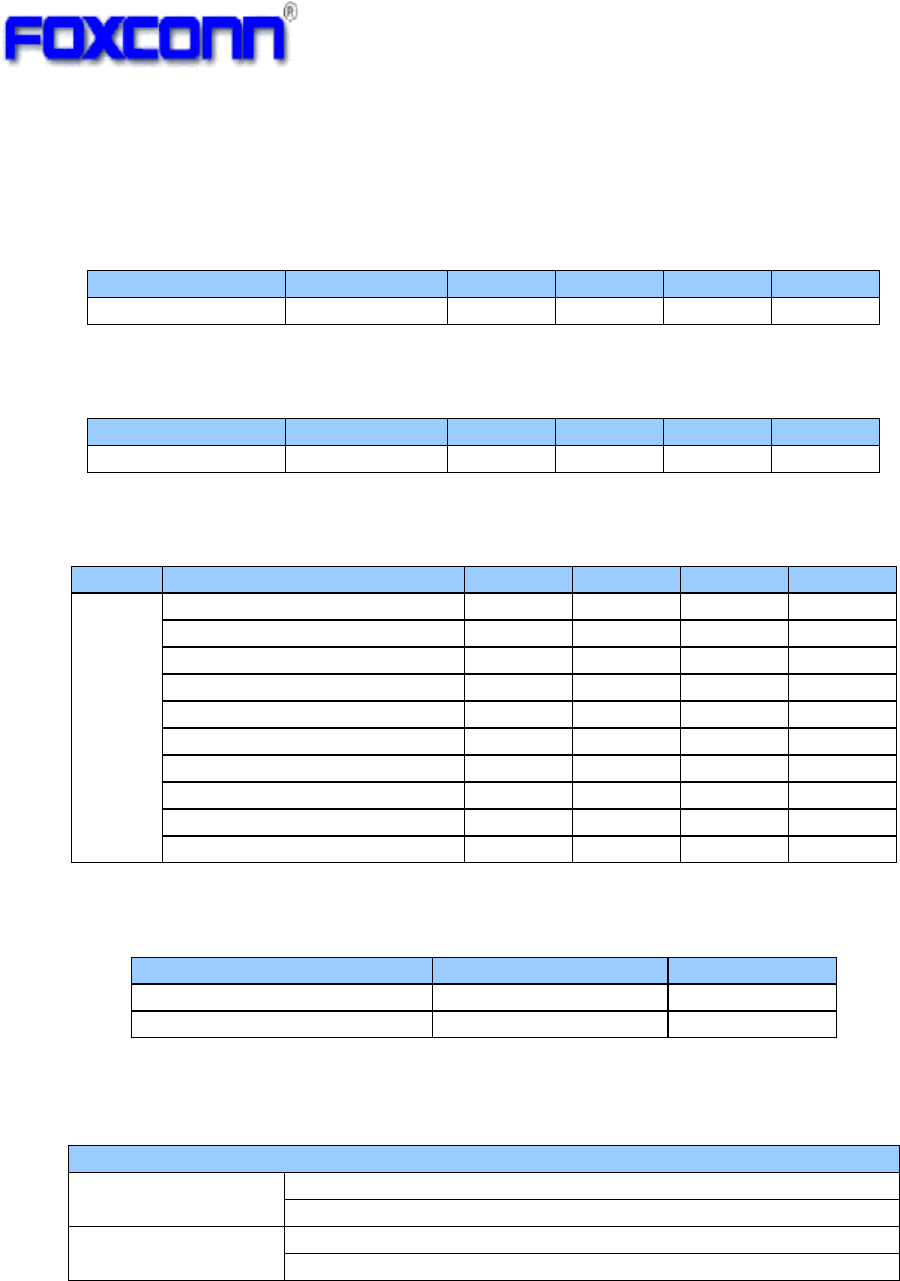
4.3 802.11n HT20
4.4 Bluetooth Standard Specifications
Bluetooth Core Specification version 4.0:
Support all Bluetooth 4.0+HS packet types.
Operating frequency range: 2400MHz ~2483.5MHz
Modulation type:
Basic rate 1Mbps: GFSK,
Enhanced data rate 2Mbps: DQPSK
Enhanced data rate 3Mbps: 8DPSK
Items Contents
Specification IEEE802.11n HT20
Mode OFDM
Channel CH1 to CH13
Data rate (MCS index) MCS0/1/2/3/4/5/6/7
TX Characteristics Min. Typ. Max. Unit
1. Power Levels (Calibrated)
1) Target Power@MCS0
13.5 15 16.5 dBm
2) Target Power@ MCS1
13.5 15 16.5 dBm
3) Target Power@ MCS2
13.5 15 16.5 dBm
4) Target Power@ MCS3
13.5 15 16.5 dBm
5) Target Power@ MCS4
13.5 15 16.5 dBm
6) Target Power@ MCS5
13.5 15 16.5 dBm
7) Target Power@ MCS6
13.5 15 16.5 dBm
8) Target Power@ MCS7
13.5 15 16.5 dBm
2. Spectrum Mask @14dBm
1) at fc +/- 11MHz - - -20 dBr
2) at fc +/- 20MHz - - -28 dBr
3) at fc > +/-30MHz - - -45 dBr
3. Modulation Accuracy(EVM)@14dBm
1) MCS0 - - -5 dB
2) MCS1 - - -10 dB
3) MCS2 - - -13 dB
4) MCS3 - - -16 dB
5) MCS4 - - -19 dB
6) MCS5 - - -22 dB
7) MCS6 - - -25 dB
8) MCS7 - - -28 dB
4. Frequency Error -15 - +5 ppm
RX Characteristics Min. Typ. Max. Unit
5. Minimum Input Level Sensitivity
1) MCS0 (PER < 10%) - -88 -85 dBm
2) MCS1 (PER < 10%) - -85 -82 dBm
3) MCS2 (PER < 10%) - -83 -80 dBm
4) MCS3 (PER < 10%) - -80 -77 dBm
5) MCS4 (PER < 10%) - -77 -74 dBm
6) MCS5 (PER < 10%) - -73 -69 dBm
7) MCS6 (PER < 10%) - -71 -68 dBm
8) MCS7 (PER < 10%) - -70 -67 dBm
6. Maximum Input Level (PER < 10%) -20 -10 - dBm

10
5 Operation SOP
1: Install normal driver under Linux PC
2: search WiFi AP and double click to make connection
3: If connection setup is ok, PC can communicate with network through wireless AP.

11
Items Contents
Specification BT4.0+EDR
Frequenc
y
ran
g
e 2.4GHz~2.4835GHz
Data rate 1Mbps, 2Mbps, 3Mbps
- TX Characteristics - Min. Typ. Max. Unit
1. Power Levels
BT Output Power -3 1 3 dBm
2. Initial Carrier Frequenc
y
Tolerance
Average Offset -75 2 75 kHz
3. Carrier Drift
Drift Rate
DH1 -20 -3 20 kHz/50us
DH3 -20 0 20 kHz/50us
DH5 -20 4 20 kHz/50us
Average Drift
DH1 -25 -3 25 kHz
DH3 -40 -4 40 kHz
DH5 -40 -5 40 kHz
4. Modulation Characteristic
F1avg 140 164 175 kHz
F2max 115 135 kHz
F1/F2 Ratio 0.8 0.90
5. EDR Relative Transmit Power
2Mbps: P[DQPSK]-P[GFSK] -4 -0.15 1 dB
3Mbps: P[8DPSK]-P[GFSK] -4 -0.2 1 dB
6. EDR Carrier Frequency Stability and Modulation Accuracy
2Mbps: π/4 DQPSK
Initial Frequency Error: ωi -75 1.2 75 kHz
Frequency Error: ω0 -10 0 10 kHz
Block Frequency Error: ωi + ω0 -75 2 75 kHz
RMS DEVM - - 0.2
Peak DEVM - - 0.35
99% DEVM (% Symbols <=0.3) 99% 100%
3Mbps: 8DPSK
Initial Frequency Error: ωi -75 1 75 kHz
Frequency Error: ω0 -10 0 10 kHz
Block Frequency Error: ωi + ω0 -75 1.6 75 kHz
RMS DEVM - - 0.13
Peak DEVM - - 0.25
99% DEVM (% Symbols <=0.13) 99% 100%
7. Tx Spurious Emission
30MHz- 1GHz - -60 -36 dBm
1GHz – 13.2GHz - -60 -30 dBm
12
Items Contents
Specification BT4.0+EDR
Frequenc
y
ran
g
e 2.4GHz~2.4835GHz
Data rate 1Mbps, 2Mbps, 3Mbps
- RX Characteristics - Min. Typ. Max. Unit
1. Minimum Input Level Sensitivit
y
GFSK (1Mbps) - - -79 dBm
π/4 DQPSK (2Mbps) ---72 dBm
8DPSK (3Mbps) - - -72 dBm
2. Maximum Input Level
GFSK (1Mbps) -20 0 dBm
π/4 DQPSK (2Mbps) -20 0 dBm
8DPSK (3Mbps) -20 0 dBm
3. Rx Emission
30MHz- 1GHz - - -57 dBm
1GHz – 13.2GHz - - -47 dBm
13
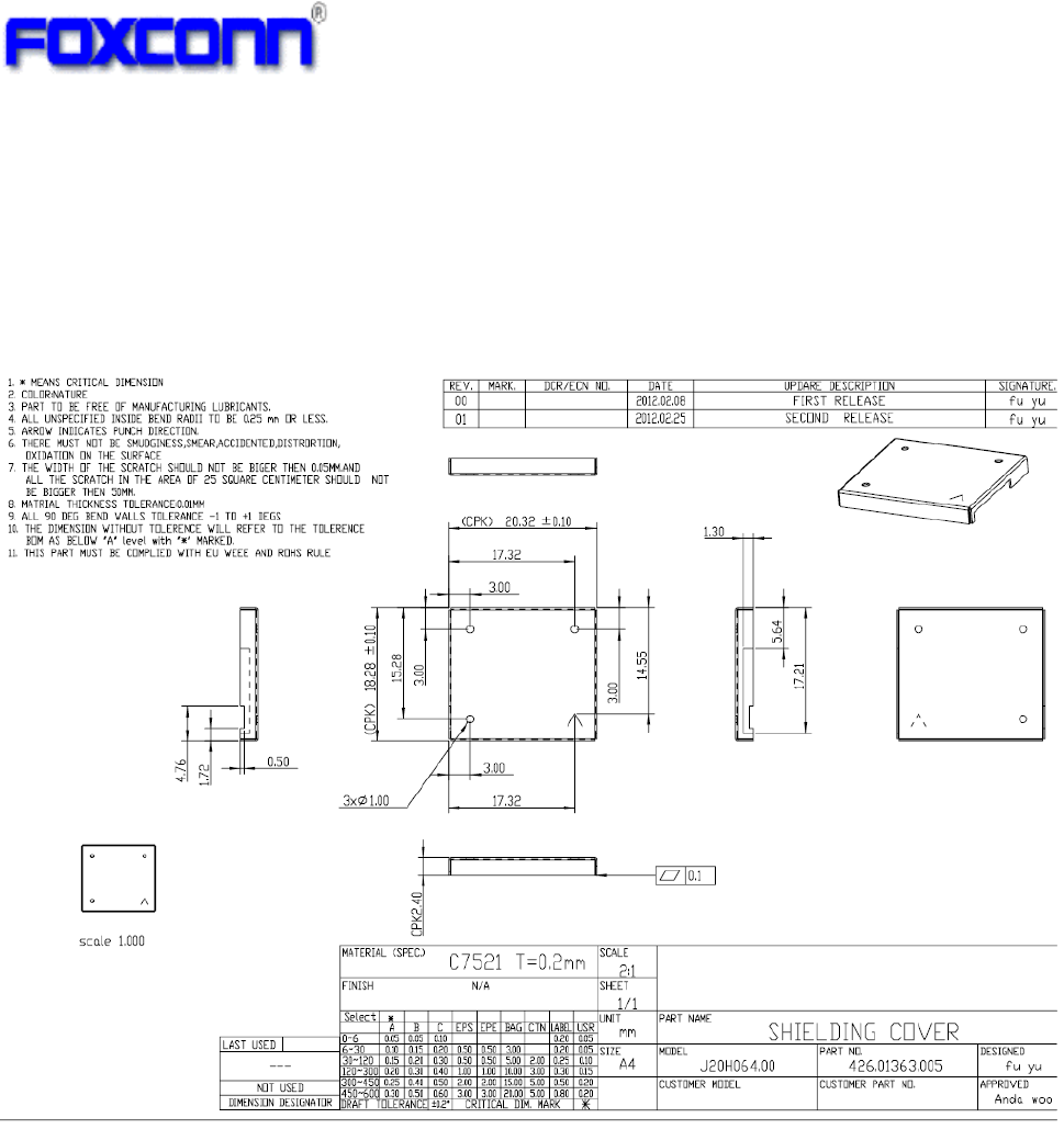
6 Mechanical Specifications
6.1 Shielding Cover Dimension
Dimension (LxWxH): 20.32mm x 18.28mm x 2.4mm
Thickness: 0.2mm
14
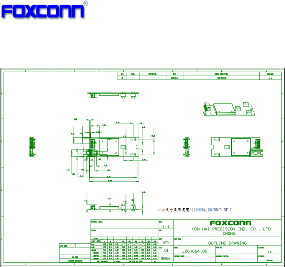
6.2 PCB Assembly Dimension
Dimension (W x Lx H ): 51.8mmx20mmx0.9mm
PCB: 2 layer HF-FR4 design
Industry Canada statement:
This device complies with RSS-210 of the Industry Canada Rules. Operation is subject to
the following two conditions: (1) This device may not cause harmful interference, and (2)
this device must accept any interference received, including interference that may cause
undesired operation.
Ce dispositif est conforme à la norme CNR-210 d'Industrie Canada applicable aux
appareils radio exempts de licence. Son fonctionnement est sujet aux deux conditions
suivantes: (1) le dispositif ne doit pas produire de brouillage préjudiciable, et (2) ce
dispositif doit accepter tout brouillage reçu, y compris un brouillage susceptible de
provoquer un fonctionnement indésirable.
Radiation Exposure Statement:
This equipment complies with IC radiation exposure limits set forth for an uncontrolled
environment. This equipment should be installed and operated with minimum distance
20cm between the radiator & your body.
Déclaration d'exposition aux radiations:
Cet équipement est conforme aux limites d'exposition aux rayonnements IC établies pour
un environnement non contrôlé. Cet équipement doit être installé et utilisé avec un
minimum de 20 cm de distance entre la source de rayonnement et votre corps.
This device is intended only for OEM integrators under the following conditions:

15
(For module device use)
1) The antenna must be installed such that 20 cm is maintained between the antenna and
users, and
2) The transmitter module may not be co-located with any other transmitter or antenna.
As long as 2 conditions above are met, further transmitter test will not be required.
However, the OEM integrator is still responsible for testing their end-product for any
additional compliance requirements required with this module installed.
Cet appareil est conçu uniquement pour les intégrateurs OEM dans les conditions
suivantes: (Pour utilisation de dispositif module)
1) L'antenne doit être installée de telle sorte qu'une distance de 20 cm est respectée entre
l'antenne et les utilisateurs, et
2) Le module émetteur peut ne pas être coïmplanté avec un autre émetteur ou antenne.
Tant que les 2 conditions ci-dessus sont remplies, des essais supplémentaires sur
l'émetteur ne seront pas nécessaires. Toutefois, l'intégrateur OEM est toujours
responsable des essais sur son produit final pour toutes exigences de conformité
supplémentaires requis pour ce module installé.
IMPORTANT NOTE:
In the event that these conditions can not be met (for example certain laptop configurations
or co-location with another transmitter), then the Canada authorization is no longer
considered valid and the IC ID can not be used on the final product. In these
circumstances, the OEM integrator will be responsible for re-evaluating the end product
(including the transmitter) and obtaining a separate Canada authorization.
NOTE IMPORTANTE:
Dans le cas où ces conditions ne peuvent être satisfaites (par exemple pour certaines
configurations d'ordinateur portable ou de certaines co-localisation avec un autre
émetteur), l'autorisation du Canada n'est plus considéré comme valide et l'ID IC ne peut
pas être utilisé sur le produit final. Dans ces circonstances, l'intégrateur OEM sera chargé
de réévaluer le produit final (y compris l'émetteur) et l'obtention d'une autorisation distincte
au Canada.
End Product Labeling
This transmitter module is authorized only for use in device where the antenna may be
installed such that 20 cm may be maintained between the antenna and users. The final
end product must be labeled in a visible area with the following: “Contains IC: 2878D-
J20H064”.
Plaque signalétique du produit final
Ce module émetteur est autorisé uniquement pour une utilisation dans un dispositif où
l'antenne peut être installée de telle sorte qu'une distance de 20cm peut être maintenue
entre l'antenne et les utilisateurs. Le produit final doit être étiqueté dans un endroit visible
avec l'inscription suivante: "Contient des IC: 2878D- J20H064".
Manual Information To the End User
The OEM integrator has to be aware not to provide information to the end user regarding
how to install or remove this RF module in the user’s manual of the end product which
integrates this module.
The end user manual shall include all required regulatory information/warning as show in
this manual.
Manuel d'information à l'utilisateur final
L'intégrateur OEM doit être conscient de ne pas fournir des informations à l'utilisateur final
quant à la façon d'installer ou de supprimer ce module RF dans le manuel de l'utilisateur
du produit final qui intègre ce module.
Le manuel de l'utilisateur final doit inclure toutes les informations réglementaires requises
et avertissements comme indiqué dans ce manuel.

16
Federal Communication Commission Interference Statement
This device complies with Part 15 of the FCC Rules. Operation is subject to the
following two conditions: (1) This device may not cause harmful interference, and
(2) this device must accept any interference received, including interference that
may cause undesired operation.
This equipment has been tested and found to comply with the limits for a Class B
digital device, pursuant to Part 15 of the FCC Rules. These limits are designed to
provide reasonable protection against harmful interference in a residential
installation. This equipment generates, uses and can radiate radio frequency energy
and, if not installed and used in accordance with the instructions, may cause
harmful interference to radio communications. However, there is no guarantee that
interference will not occur in a particular installation. If this equipment does cause
harmful interference to radio or television reception, which can be determined by
turning the equipment off and on, the user is encouraged to try to correct the
interference by one of the following measures:
- Reorient or relocate the receiving antenna.
- Increase the separation between the equipment and receiver.
- Connect the equipment into an outlet on a circuit different from that
to which the receiver is connected.
- Consult the dealer or an experienced radio/TV technician for help.
FCC Caution: Any changes or modifications not expressly approved by the party
responsible for compliance could void the user's authority to operate this equipment.
This transmitter must not be co-located or operating in conjunction with any other
antenna or transmitter.
Radiation Exposure Statement:
This equipment complies with FCC radiation exposure limits set forth for an
uncontrolled environment. This equipment should be installed and operated with
minimum distance 20cm between the radiator & your body.
This device is intended only for OEM integrators under the following conditions:
1) The antenna must be installed such that 20 cm is maintained between the antenna
and users, and
2) The transmitter module may not be co-located with any other transmitter or
antenna.
As long as 2 conditions above are met, further transmitter test will not be required.
However, the OEM integrator is still responsible for testing their end-product for any
additional compliance requirements required with this module installed
IMPORTANT NOTE: In the event that these conditions can not be met (for example
certain laptop configurations or co-location with another transmitter), then the FCC
authorization is no longer considered valid and the FCC ID can not be used on the
final product. In these circumstances, the OEM integrator will be responsible for
reevaluating
the end product (including the transmitter) and obtaining a separate FCC
authorization.
End Product Labeling

17
This transmitter module is authorized only for use in device where the antenna may be
installed such that 20 cm may be maintained between the antenna and users. The
final end product must be labeled in a visible area with the following: “Contains FCC
ID: MCLJ20H064”. The grantee's FCC ID can be used only when all FCC compliance
requirements are met.
Manual Information To the End User
The OEM integrator has to be aware not to provide information to the end user
regarding how to install or remove this RF module in the user’s manual of the end
product which integrates this module.
The end user manual shall include all required regulatory information/warning as show
in this manual.
For Taiwan 警語: (電信管制射頻器材使用)
經型式認證合格之低功率射頻電機,非經許可,公司、商號或使用者均不得擅自變更頻
率、加大功率或變更原設計之特性及功能。
低功率射頻電機之使用不得影響飛航安全及干擾合法通信;經發現有干擾現象時,應立
即停用,並改善至無干擾時方得繼續使用。前項合法通信,指依電信法規定作業之無線
電通信。低功率射頻電機須忍受合法通信或工業、科學及醫療用電波輻射性電機設備之
干擾。
Note: 1. 本模組於取得認證後將依規定於模組本體標示審驗合格標籤 2. 系統廠商應於平
台上標示「本產品內含射頻模組: XXXyyyLPDzzzz-x (NCC ID) 」字樣